

Samsung TX-T2781 User Manual

COLOR TELEVISION
TX-T2781
TX-T2782
TX-T2082
Owner’s
Instructions
Register your product at www.samsung.com/global/register
Record your Model and Serial number here for future reference.
▪ Model _______________ ▪ Serial No. _______________
Contents
General Information
Accessories ............................................................................. 3
Viewing the Control Panel ....................................................... 3
Viewing the Connection Panel ................................................ 4
Remote Control ....................................................................... 5
Connection
Connecting VHF and UHF Antennas ...................................... 6
Connecting Cable TV .............................................................. 6
Connecting a VCR .................................................................. 7
Connecting a Camcorder ........................................................ 7
Connecting a DVD Player/Set-Top Box .................................. 8
Connecting an Amplifier/DVD Home Theater - Analog ........... 8
Operation
Plug & Play Feature ................................................................ 9
Memorizing the Channels ..................................................... 10
To Select the Source ............................................................. 11
To Edit the Input Source Name ............................................. 11
Picture Control
Using Automatic Picture Settings .......................................... 11
Changing the Screen Size .................................................... 12
Digital Noise Reduction ......................................................... 12
Tilt (TX-T2781/TX-T2782 only) ............................................. 13
Sound Control
Using Automatic Sound Settings ........................................... 13
Customizing the Sound ......................................................... 13
Choosing a Multi-Channel Sound (MTS) Track - Digital ....... 14
Choosing a Multi-Channel Sound (MTS) Track - Analog ...... 14
Automatic Volume Control .................................................... 14
Using Pseudo Stereo ............................................................ 15
Using Turbo Plus ................................................................... 15
Channel Control
Clearing Scrambled Channels - Digital ................................. 15
Adding and Erasing Channels - Analog ................................ 15
Adding and Erasing Channels - Digital ................................. 16
Fine Tuning Analog Channels - Analog ................................. 16
Labeling Channels - Analog .................................................. 16
Checking the Digital-Signal Strength - Digital ....................... 17
Using the R.Surf Feature ...................................................... 17
Function Description
Selecting a Menu Language ................................................. 17
Setting the Time .................................................................... 18
Viewing Closed Captions
(On-Screen Text Messages) - Digital .................................... 19
Viewing Closed Captions
(On-Screen Text Messages) - Analog ................................... 19
Setting the Blue Screen Mode .............................................. 20
Setting the On/Off Melody ..................................................... 20
Using the V-Chip ................................................................... 20
Upgrading the Software ........................................................ 23
Appendix
Identifying Problems ............................................................. 23
Specifications
Symbols
☛ ➢
Press
Important
Note
One-Touch
Button
Important Warranty Information Regarding Television Format Viewing
Standard screen format televisions(4:3, the aspect ratio of the screen width to height) are primarily designed to view standard format
full-motion video. The images displayed on them should primarily be in the standard 4:3 ratio format and constantly moving. Displaying
stationary graphics and images on screen, such as the dark top and bottom letterbox bars(wide screen pictures), should be limited to no
more than 15% of the total television viewing per week.
Wide screen format televisions(16:9, the aspect ratio of the screen width to height) are primarily designed to view wide screen format
full-motion video. The images displayed on them should primarily be in the wide screen 16:9 ratio format, or expanded to fill the screen
if your model offers this feature, and constantly moving. Displaying stationary graphics and images on screen, such as the dark sidebars on non-expanded standard format television video and programming, should be limited to no more than 15% of the total television
viewing per week.
Additionally, viewing other stationary images and text such as stock market reports, video game displays, station logos, web sites or
computer graphics and patterns, should be limited as described above for all televisions. Displaying any stationary images that
exceed the above guidelines can cause uneven aging of picture tubes(CRTs) that leave subtle, but permanent burned-in ghost
images in the television picture. To avoid this, vary the programming and images, and primarily display full screen moving
images, not stationary patterns or dark bars. On television models that offer picture sizing features, use these controls to view the
different formats as a full screen picture.
Be careful in the selection and duration of television formats used for viewing. Uneven CRT aging as a result of format selection and
use, as well as other burned-in images, is not covered by your Samsung limited warranty.
© 2007 Samsung Electronics Co., Ltd. All rights reserved.
English - 2
English - 3
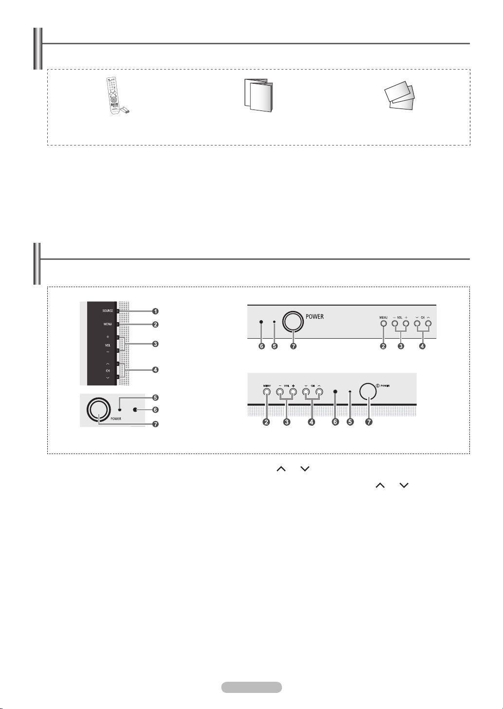
Accessories
Please make sure the following items are included with your TV.
If any items are missing, contact your dealer.
Remote Control (AA59-00405B)/
AAA Batteries
Owner’s Instructions/
Safety Guide Manual
Viewing the Control Panel
You can control your TV’s basic features, including the on-screen menu.
To use the more advanced features, you must use the remote control.
TX-T2781
TX-T2782
TX-T2082
Warranty Cards/
Registration Card
The product color and shape may vary depending on the model.
➢
1
SOURCE
Toggles between all the available input sources (TV, AV1,
AV2, Component).
In the on-screen menu, use this button as you would use the
ENTER button on the remote control.
2
MENU
Press to see an on-screen menu of your TV’s features.
3
+ VOL −
Press to increase or decrease the volume.
In the on-screen menu, use the + VOL – buttons as you would
use the ◄ and ► buttons on the remote control.
4
CH
Press to change channels.
In the on-screen menu, use the CH buttons as you
would use the ▲ and ▼ buttons on the remote control.
5
Power Indicator
Lights up when you turn the power off.
- Power Off: Red
- Power On: Off
6
Remote Control Sensor
Aim the remote control towards this spot on the TV.
7
POWER
Press to turn the TV on and off.
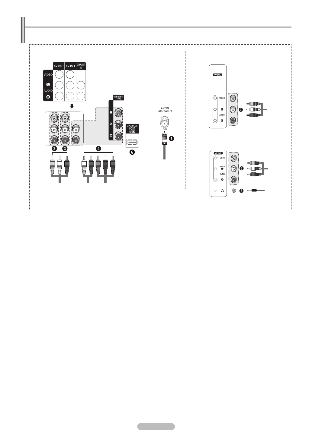
Viewing the Connection Panel
Use the rear panel jacks to connect A/V components that will be connected continuously, such as VCR or DVD players.
Side of the TVRear of the TV
TX-T2781/TX-T2782
TX-T2082
The product color and shape may vary depending on the model.
➢
1
ANT IN (AIR/CABLE)
Connect to an antenna(air) or cable TV system.
2
AV OUT
Connect to the audio/video input jacks of a recording VCR.
3
AV IN 1 / AV IN 2
Video and audio inputs for external devices, such as a
camcorder or VCR.
4
COMPONENT IN
Connect Component video/audio.
5
Headphone
Connect a set of external headphones to this jack for private
listening.
6
UPGRADE PORT (USB)
Connect for service and software upgrade.
English - 4
English - 5
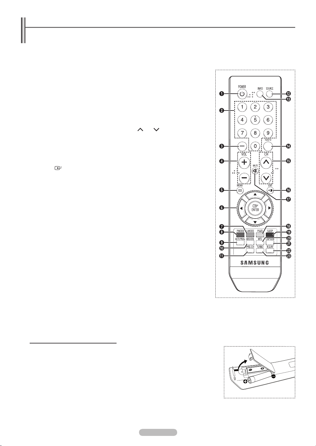
Remote Control
You can use the remote control up to a distance of about 23 feet from the TV. When using the remote control, always point it
directly at the TV.
This is a special remote control for the visually impaired, and has Braille points on the POWER, Channel, and Volume buttons.
➢
The performance of the remote control may be affected by bright light.
1
POWER
Turns the TV on and off.
2
NUMERIC BUTTONS
Press to directly select a channel.
3
–
Press to select additional channels
being broadcast by the same station.
For example, to select channel “543”, press “54”, then press “–” and “3”.
4
VOL +, VOL –
Press to increase or decrease the
volume.
5
MENU
Displays the main on-screen menu.
6
UP▲/DOWN▼/LEFT◄/RIGHT►/
ENTER
Use to select on-screen menu items
and change menu values.
7
S.MODE
Press to select the sound mode.
8
P.MODE
Press to select the picture mode.
9
AUTO PROG.
Press to automatically store selected
Air/Cable channels.
0
ADD/DEL
Use to store and delete channels
to/from memory.
!
PRE-CH
Tunes to the previous channel.
@
SOURCE
Press to display all of the available
video sources.
#
INFO
Press to display information on the
TV screen.
$
TV/DTV
Press to switch between TV (Analog)
and DTV (Digital) mode.
%
CH , CH
Press to change channels.
^
EXIT
Press to exit from the menu.
&
MUTE
Press to temporarily cut off the sound.
*
P.SIZE
Press to change the screen size.
(
SLEEP
Press to select a preset time interval
for automatic shut off.
)
MTS
Press to choose stereo, mono
or Separate Audio Program(SAP
broadcast).
a
CAPTION
Controls the caption decoder.
b
R.SURF
Press to automatically return to a
preferred channel after a user-preset
time delay.
c
TURBO
Press to select Turbo sound.
Installing Batteries in the Remote Control
1 Lift the cover at the back of the remote control upward as shown in the figure.
2 Install two AAA size batteries.
3 Replace the cover.
Make sure to match the + and – ends of the batteries with the diagram inside the
➢
compartment.
Do not mix battery types, i.e. alkaline and manganese.
Remove the batteries and store them in a cool and dry place if you won’t be using the
➢
remote control for a long time. The remote control can be used up to about 23 feet from
the TV. (Assuming typical TV usage, the batteries last for about one year.)
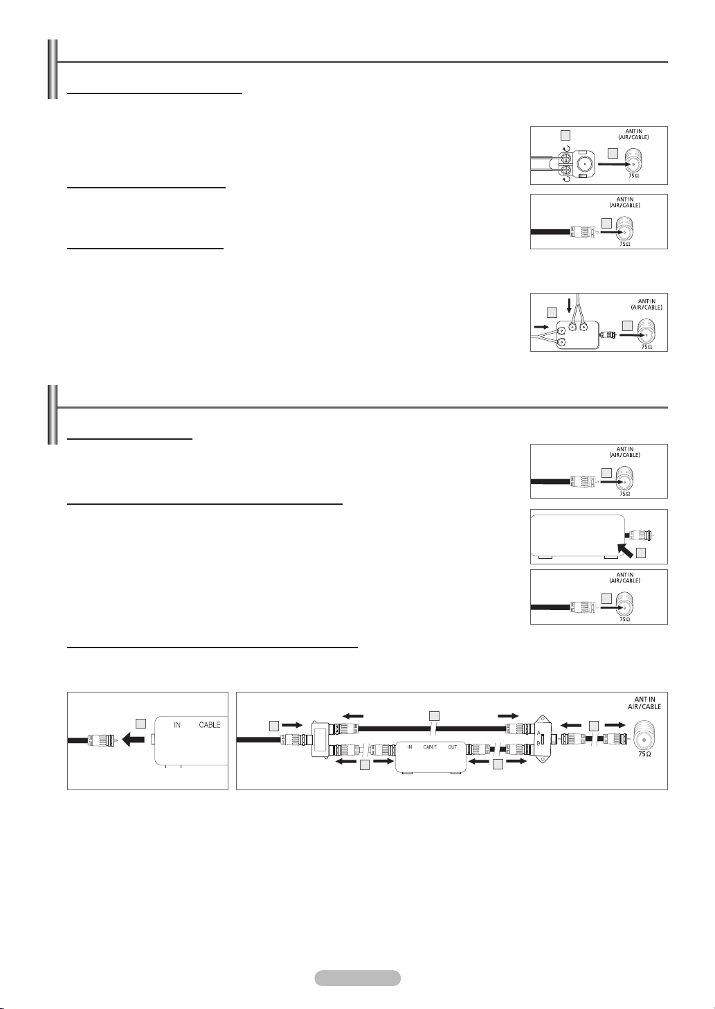
Connecting VHF and UHF Antennas
Antennas with 300 Ω Flat Twin Leads
If you are using an off-air antenna(such as a roof antenna or “rabbit ears”) that has 300 Ω twin flat leads, follow the directions
below.
1 Place the wires from the twin leads under the screws on a 300-75 Ω adapter(not supplied).
Use a screwdriver to tighten the screws.
2 Plug the adaptor into the ANT IN (AIR/CABLE) terminal on the back of the TV.
1
2
Antennas with 75 Ω Round Leads
1 Plug the antenna lead into the ANT IN (AIR/CABLE) terminal on the back of the TV.
1
Separate VHF and UHF Antennas
If you have two separate antennas for your TV(one VHF and one UHF), you must combine the two antenna signals before
connecting the antennas to the TV. This procedure requires an optional combiner-adaptor(available at most electronics
shops).
1 Connect both antenna leads to the combiner.
2 Plug the combiner into the ANT IN (AIR/CABLE) terminal on the back of the TV.
1
2
Connecting Cable TV
Cable without a Cable Box
1 Plug the incoming cable into the ANT IN (AIR/CABLE) terminal on the back of the TV.
Because this TV is cable-ready, you do not need a cable box to view unscrambled cable
➢
channels.
1
Connecting to a Cable Box that Descrambles All Channels
1 Find the cable that is connected to the ANT OUT terminal on your cable box.
This terminal might be labeled “ANT OUT”, “VHF OUT” or simply, “OUT”.
➢
2 Connect the other end of this cable to the ANT IN (AIR/CABLE) terminal on the back of the TV.
ANT OUTANT IN
1
2
Connecting to a Cable Box that Descrambles Some Channels
If your cable box descrambles only some channels(such as premium channels), follow the instructions below. You will need a
two-way splitter, an RF (A/B) switch, and four lengths of Antenna cable. (These items are available at most electronics stores.)
1
Cable Box
2
Incoming
cable
Splitter
1 Find and disconnect the cable that is connected to the
ANT IN terminal on your cable box.
This terminal might be labeled “ANT IN”, “VHF IN” or
➢
simply, “IN”.
2 Connect this cable to a two-way splitter.
3 Connect an Antenna cable between an OUT terminal on
the splitter and the IN terminal on the cable box.
4 Connect an Antenna cable between the ANT OUT terminal
on the cable box and the B-IN terminal on the RF(A/B)
switch.
3
5 Connect another cable between the other OUT terminal on
6 Connect the last Antenna cable between the OUT terminal
After you have made this connection, set the A/B switch to the
“A” position for normal viewing. Set the A/B switch to the “B”
position to view scrambled channels. (When you set the A/B
switch to “B”, you will need to tune your TV to the cable box’s
output channel, which is usually channel 3 or 4.)
5
Cable Box
4
RF (A/B)
Switch
6
TV Rear
the splitter and the A-IN terminal on the RF (A/B) switch.
on the RF (A/B) switch and the ANT IN (AIR/CABLE)
terminal on the back of the TV.
English - 6
English - 7
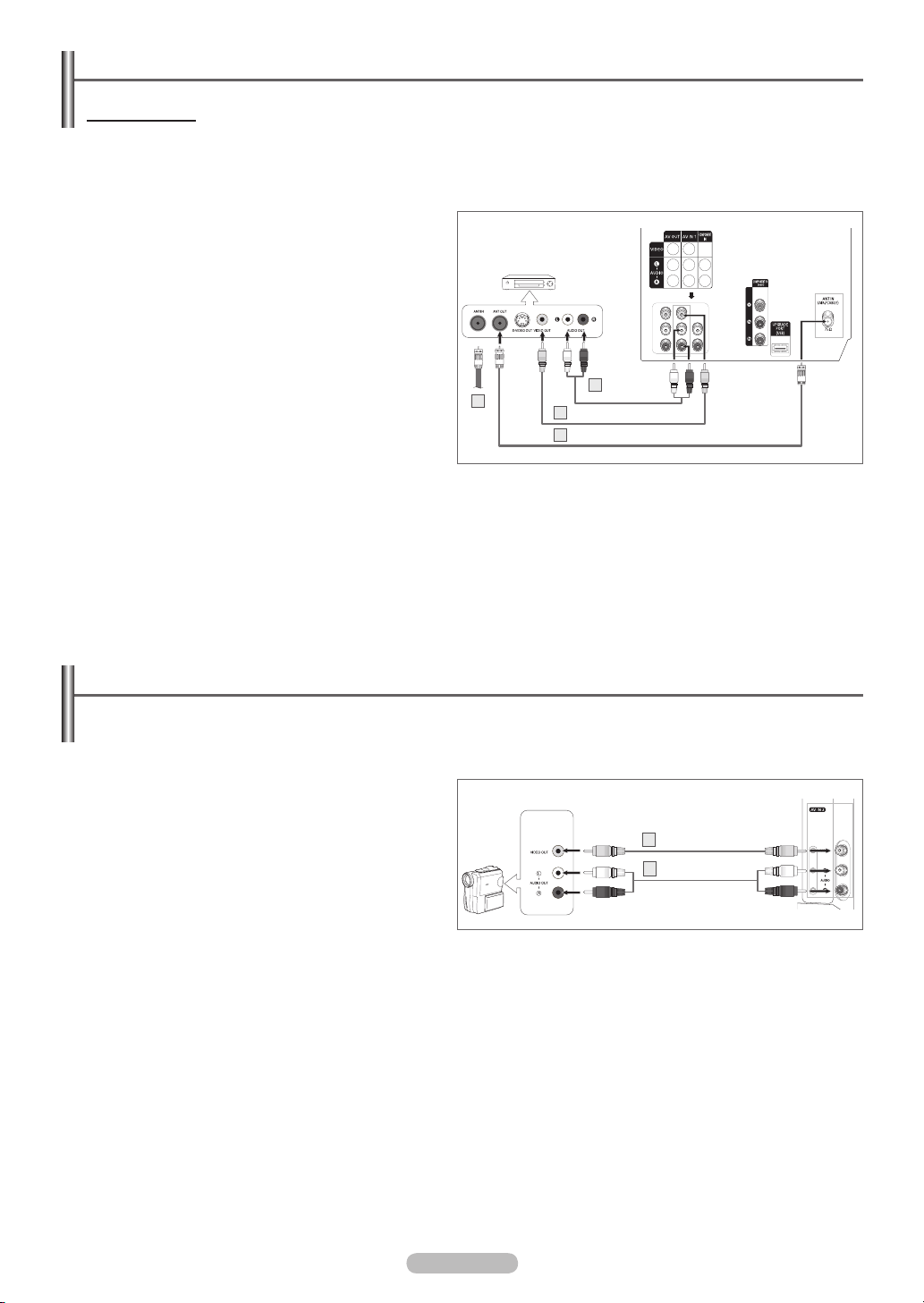
Connecting a VCR
Video Connection
These instructions assume that you have already connected your TV to an antenna or a cable TV system(according to the
instructions on page 6). Skip step 1 if you have not yet connected to an antenna or a cable system.
Each VCR has a different back panel configuration.
➢
When connecting a VCR, match the color of the connection terminal to the cable.
1 Unplug the cable or antenna from the back of the TV.
2 Connect the cable or antenna to the ANT IN terminal on
the back of the VCR.
3 Connect an Antenna cable between the ANT OUT terminal
on the VCR and the ANT IN (AIR/CABLE) terminal on the
TV.
4 Connect a Video Cable between the VIDEO OUT jack on
the VCR and the AV IN 1 [VIDEO] jack on the TV.
5 Connect Audio Cables between the AUDIO OUT jacks on
the VCR and the AV IN 1 [L-AUDIO-R] jacks on the TV.
If you have a “mono” (non-stereo) VCR, use a
➢
Y-connector(not supplied) to hook up to the right and
left audio input jacks of the TV. If your VCR is stereo,
you must connect two cables.
Also, you can connect to AV IN 2 on the side panel of TV.
➢
VCR
Audio Cable
5
2
(Not supplied)
Video Cable(Not supplied)4
3
Antenna cable(Not supplied)
Rear of the TV
Connecting a Camcorder
The side panel jacks on your TV make it easy to connect a camcorder to your TV.
They allow you to view the camcorder tapes without using a VCR.
Each Camcorder has a different back panel configuration.
➢
When connecting a Camcorder, match the color of the connection terminal to the cable.
1 Connect a Video Cable between the AV IN 2 [VIDEO] jack
on the TV and the VIDEO OUT jack on the camcorder.
2 Connect Audio Cables between the AV IN 2
[L-AUDIO-R] jacks on the TV and the AUDIO OUT jacks
on the camcorder.
Camcorder
1
Video Cable(Not supplied)
Audio Cable(Not supplied)
2
Side of the TV
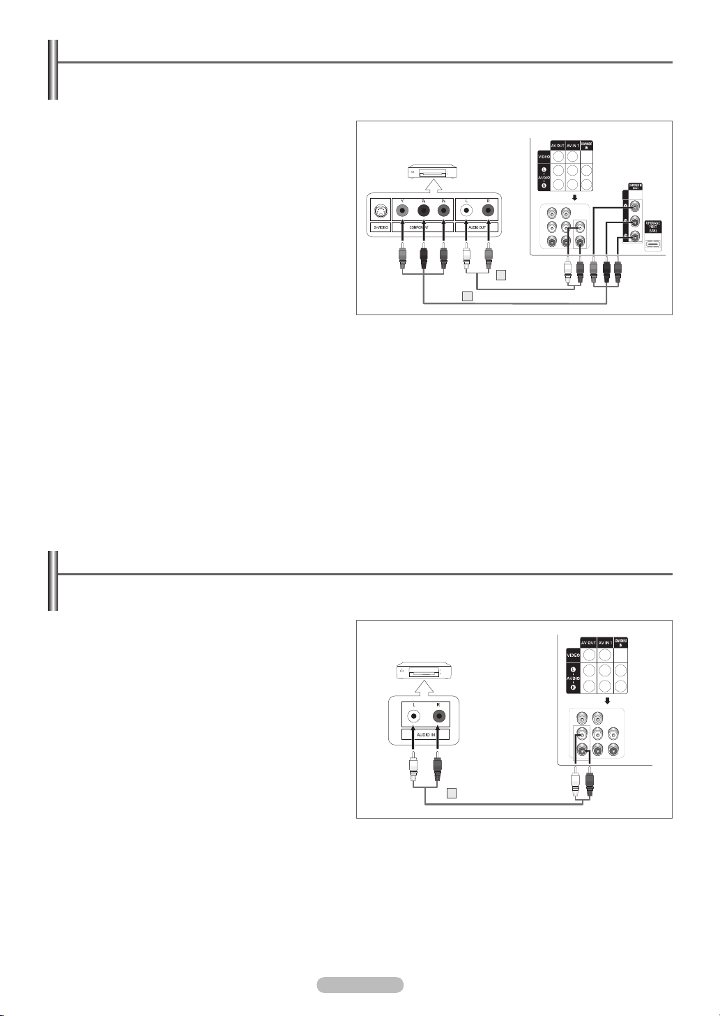
Connecting a DVD Player/Set-Top Box
The rear panel jacks on your TV make it easy to connect a DVD player/Set-Top Box.
Each DVD Player/Set-Top Box has a different back panel configuration.
➢
When connecting a DVD Player/Set-Top Box, match the color of the connection terminal to the cable.
1 Connect Component Cables between the COMPONENT
IN [Y, PB, PR] jacks on the TV and the COMPONENT OUT
[Y, PB, PR] jacks on the DVD Player/Set-Top Box.
2 Connect Audio Cables between the COMPONENT IN
[L-AUDIO-R] jacks on the TV and the AUDIO OUT jacks
on the DVD Player/Set-Top Box.
Component video separates the video into Y(Luminance
➢
(brightness)), PB(Blue), and PR(Red) for enhanced video
quality. Be sure to match the component video and audio
connections.
For example, if connecting the video cable to
COMPONENT IN, connect the audio cable to
COMPONENT IN also.
This product is an SD-grade DTV and must be connected
➢
in the resolution of 480i.
If this product is connected in the resolution of 480p, 720p
or 1080i, the screen may be displayed abnormally or may
not be displayed at all.
DVD Player/Set-Top Box
Audio Cable
2
(Not supplied)
Component Cable(Not supplied)
1
Rear of the TV
Connecting an Amplifier/DVD Home Theater - Analog
Each Amplifier/DVD Home Theater has a different back panel configuration.
➢
When connecting an Amplifier/DVD Home Theater, match the color of the connection terminal to the cable.
1 Connect Audio Cables between the AV OUT
[L-AUDIO-R] on the TV and AUDIO IN on the Amplifier/
DVD Home Theater.
When an audio amplifier is connected to the AUDIO OUT
[L-AUDIO-R] terminals: Decrease the volume of the TV,
and adjust the volume level with the Amplifier’s volume
control.
Amplifier/
DVD Home Theater
1
Audio Cable(Not supplied)
Rear of the TV
English - 8
 Loading...