

SAMSUNG TX20P14X, TW-14N5R, TX-20P1F, TW14P1F, TF20P1D4S Service Manual

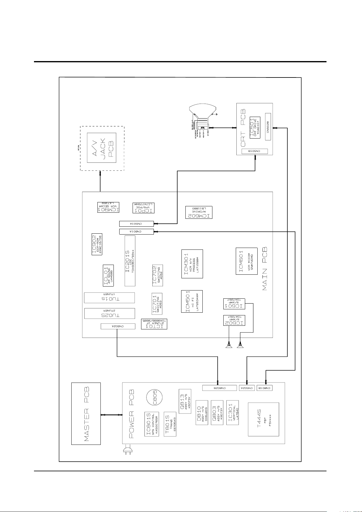
8. Block Diagrams
8-1 Notes
Block Diagrams
Samsung Electronics 8-1
The TVCR’s 1st and 2nd tuners are “multi-system.” compatible:
IC201S (TDA9361/9381) is the video, chroma, and deflection (UOC) IC .
8-1-1 TAPE PLAYBACK (REGARDLESS OF ORIGINAL RECORDING SYSTEM)
If the output PB signal of micom pin 12 is high, the PB signal outputs from ICM301 pin 29, passes
through IC 702 pins 2 and 3 and out to another VCR . The output signal of IC701 pin 1 (pin 15)
outputs from IC201S pin 42 .
8-1-2 VIEWING NORMAL CHANNEL WHILE RECORDING A SCRAMBLED CHANNEL:
The output CVBS (Composite Video Signal) of the 2nd IF outputs to IC702 pin 3 when the VCRmicom’s
pin 13 (VCR tuner high) is high . The decoded signal goes to IC701 pin 2, where it is fed to IC 701 pin
9 (high output of VCR micom’s’ pin 11— AV/Tuner), and out to VCR pin 4 for recording.
8-1-3 VIEWING A SCRAMBLED CHANNEL WHILE RECORDING AN UNSCRAMBLED CHANNEL.
The output CVBS of the 2nd IF is fed from IC701 pin 5 to IC701 pin 4 (low output of VCR micom
pin 11—AV/tuner). Then it goes to the VCR PART pin 4 for recording.
The scrambled signal (CVBS) is fed to IC702 pin 1 through the 1st IF, and then to IC702 pin 3.
Then it goes to the decoder input. The descrambled signal goes to IC701 pins 2 and 15, and then to
IC201S pin 42, where it outputs as RGB.
8-1-4 SYNCHRONOUS RECORDING:
The viewer sees the signal from the 1st tuner , while the signal from the second tuner is recorded.
Audio processing for the French system type is shown in the table.
Block Diagrams
8-2 Samsung Electronics
8-2 C17A PCB Layout
 Loading...