

Samsung TI21B4DF4X, TW14N64X, TW14N64XBWT, TW21B4D4X, TW21B4D4XBWT Service Manual
...
Television Video Cassette Recorder
Chassis : C17A (TS-10 )
Model : TI21B4DF4X/XEU
TW14N54X/BWT
TW14N64X/BWT
TW21B4D4X/BWT
TX14P1DF4X/XEC
Television Video Cassette Recorder CONTENTS
Precautions
Specifications
Disassembly and Reassembly
Alignment and Adjustment
Troubleshooting
Exploded View and Parts List
Electrical Parts List
Block Diagram
Wiring Diagram
Schematic Diagrams
1.
2.
3.
4.
5.
6.
7.
8.
9.
10.

Samsung Electronics 2-1
2. Specifications
The descriptions and characteristics given in this booklet are given for information purposes only and
are subject to modification without notice.
TELEVISION PART
Colour systems PAL(option) / SECAM(option) (UK;PAL)
TV standards L/L’(option), B/G(option), D/K(option) (UK;I)
Number of channels 100 programmes
Reception range/cable TV Hyperband/interband tuner
Aerial input 75 Ohms, coaxial cable
VCR PART
Format VHS standard
(PAL / SECAM(option) / MESECAM(option) / NTSC in playback only)
Heads Video: 2 rotary heads, LP(option), 4 Heads(option)
Audio/Control: 1 stationary head (linear)
Erase: 1 full track erase head
System Video Normal CCIR
System Audio Mono / NICAM&A2-STEREO
Luminance FM azimuth recording
Colour Down converted subcarrier phase shifted direct recording
FF/REW time Less than 100 seconds in FF with E-120
Wow and flutter (WTD) 0.4% maximum (SP)
Frequency response 100 Hz - 8 KHz
GENERAL
Power supply 220-240V~, 50Hz (110-260V~, 50/60Hz; option),(160-300V~50/60Hz;Russia)
Consumption 14”15” (50W)
20”/21” (60W)
Audio output power 14”15” (2W)
20” (2W)
21” (1.0Watts x 2)
Number of loudspeakers 14”/15”/20” (1)
21” (2)
Tube size 14” (37cm/34cmV)
15” (39cm/36cmV)
20” (51cm/48cmV)
21” (55cm/51cmV)
Tube type BLACK MATRIX
Sockets 1 full RGB SCART on the rear
1 RCA input (audio and video) on the front
Earphones output (3.5 mm mini-jack)
1 aerial/cable TV coaxial input
Dimensions (W x D x H) 14” (368 x 390 x 381)
15” (411 x 401 x 417)
20” (486 x 473 x 485)
21” (520 x 495 x 508)
Weight 14” (11.1 kg)
15” (14.8 kg)
20” (19 kg)
21” (23.4 kg)
Operating temperature 5°C - 40°C (41°F - 104°F)
Relative humidity 10% - 75%
Samsung Electronics
3-1
Œ
´
ˇ
¨
ˆ
Ø
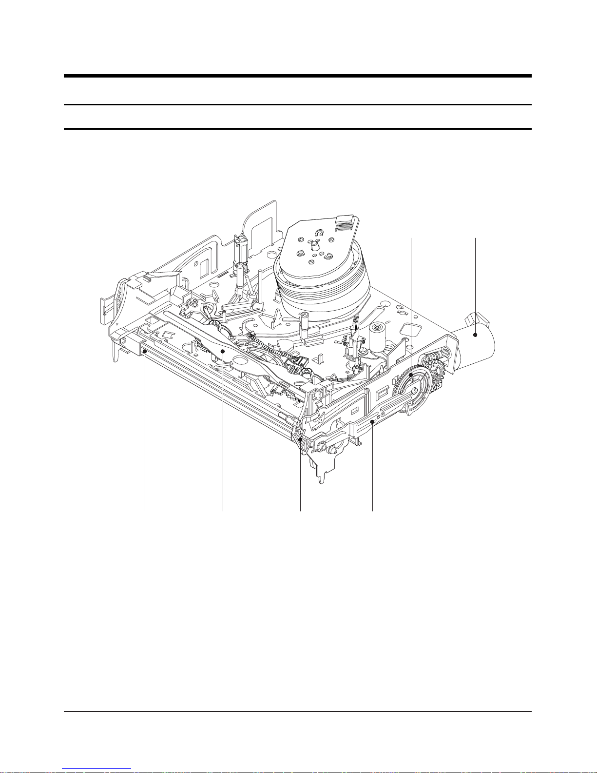
Fig. 3-1 Top parts Location-1
ΠGEAR FL CAM
´ MOTOR LOADING ASS’Y
ˇ LEVER FL ARM ASS’Y
¨ HOLDER FL CASSETTE ASS’Y
ˆ LEVER FL DOOR
Ø SLIDER FL DRIVE
3. Disassembly and Reassembly
3-1 Deck Parts Locations
3-1-1 Top View
3-2
Samsung Electronics
Disassembly and Reassembly
Œ
´ ˇ ¨
ˆ
Ø
∏”’ Ô ˝
Ò
”
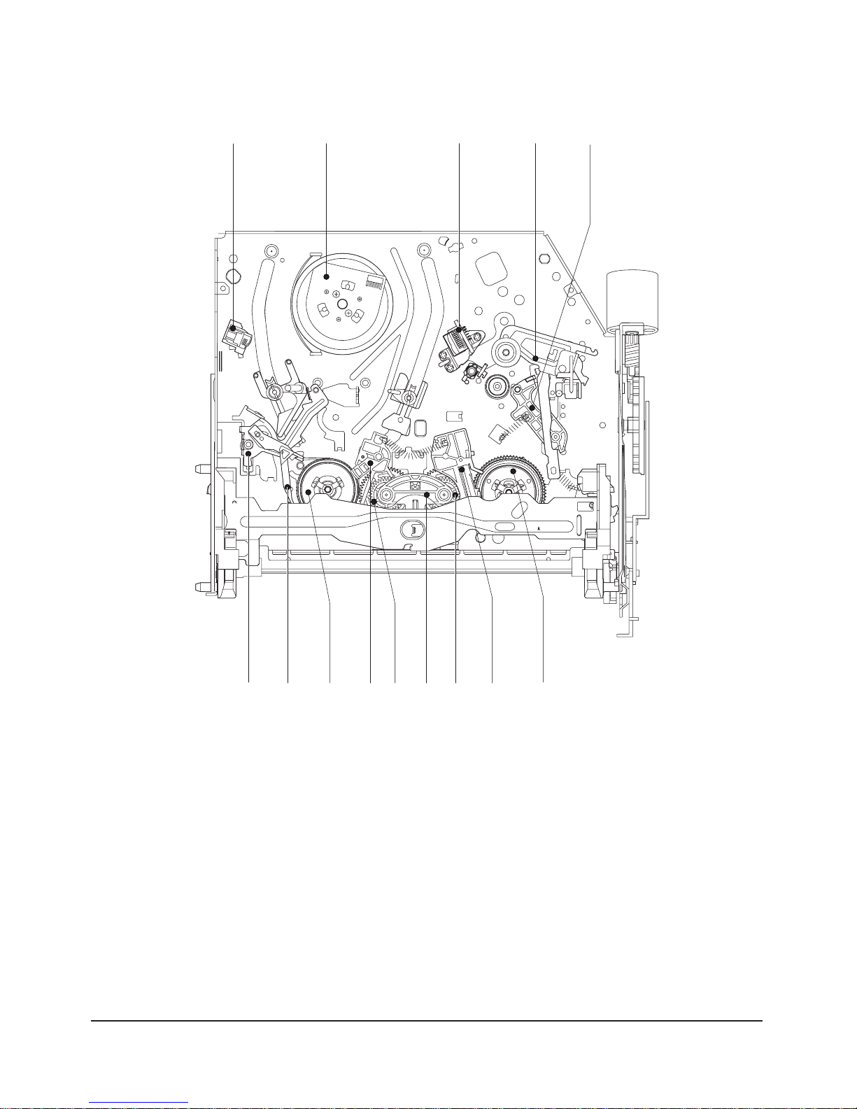
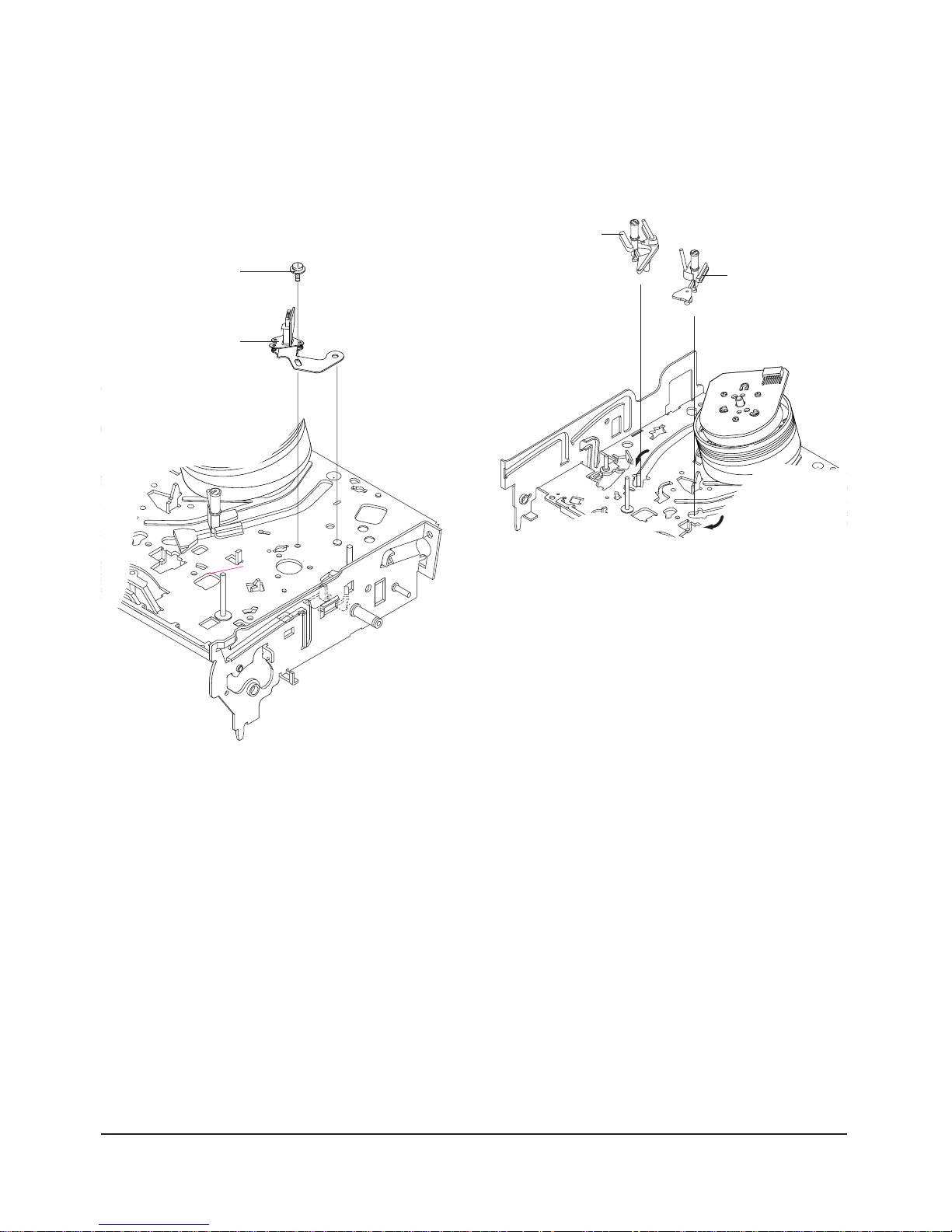
Fig. 3-2 Top Parts Location-2
ΠFE HEAD
´ CYLINDER ASS’Y
ˇ ACE HEAD ASS’Y
¨ LEVER UNIT PINCH ASS’Y
ˆ LEVER #9 GUIDE ASS’Y
Ø LEVER TENSION ASS’Y
∏ BAND BRAKE ASS’Y
” DISK S REEL
’ LEVER S BRAKE ASS’Y
˝ GEAR IDLE
Ô LEVER IDLE
LEVER T BRAKE ASS’Y
Ò DISK T REEL
Disassembly and Reassembly
Samsung Electronics
3-3
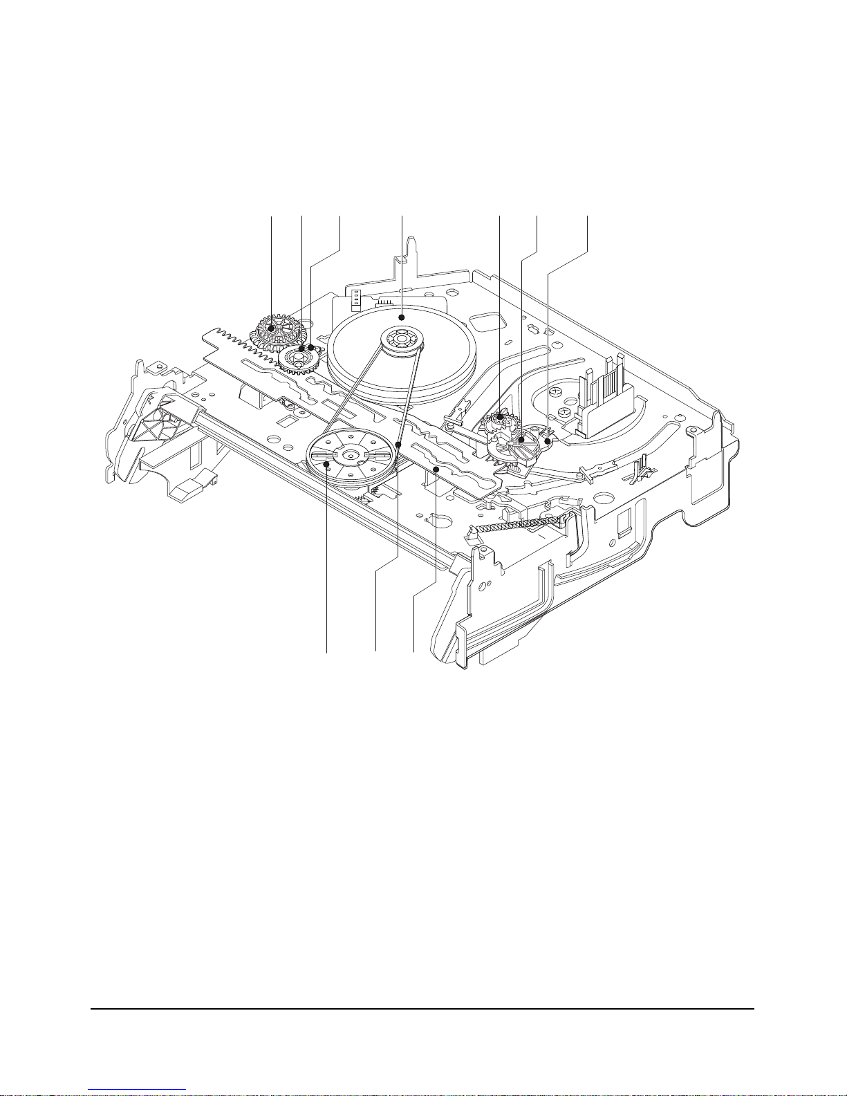
3-1-2 Bottom View
Œ
´ˇ
¨
ˆ
Ø
∏
”
’
˝
Fig. 3-3 Bottom Parts Location
ΠGEAR JOINT 1
´ GEAR JOINT 2
ˇ BRACKET GEAR
¨ MOTOR CAPSTAN ASS’Y
ˆ LEVER T LOAD ASS’Y
Ø GEAR LOADING DRIVE
∏ LEVER S LOAD ASS’Y
” HOLDER CLUTCH ASS’Y
’ BELT PULLEY
˝ SLIDER CAM
3-4
Samsung Electronics
Disassembly and Reassembly
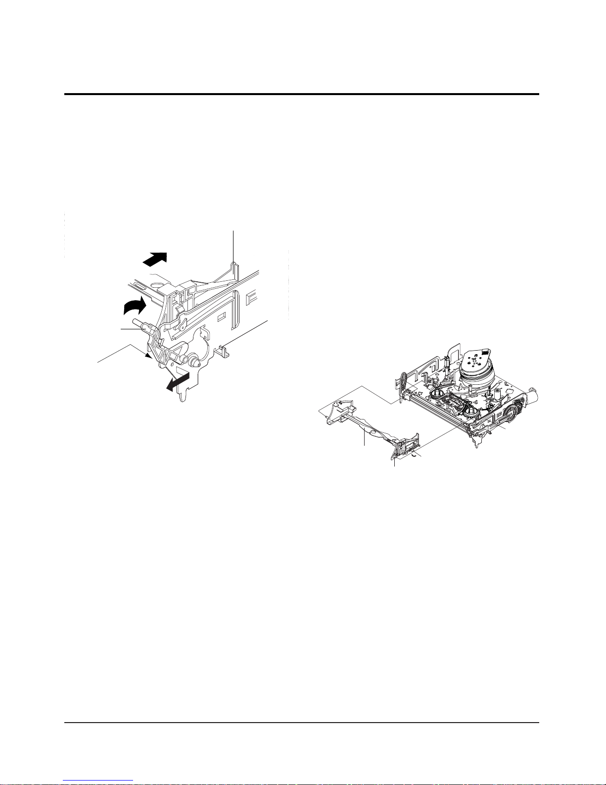
3-2-1 Lever FL Door Removal
1) Push the Holder FL Cassette Ass'y Πabout 20mm
in the direction of arrow “A”.
2) Rotate the Lever FL Door ´ in the direction of
arrow “B”.
3) Release the Hook ˇ and Remove the Lever FL
Door ´ in the direction of arrow “C”.
"B"
"C"
"A"
´ LEVER FL DOOR
ˇ HOOK
ΠHOLDER FL CASSETTE ASS'Y
3-2-2 Holder FL Cassette Ass’y Removal
1) Pull the Holder FL Cassette Ass'y Πto the eject
position.
2) Pull the Holder FL Cassette Ass'y Πas grasping
the Holder FL Cassette Ass'y Πand Lever FL
Cassette-R ´ in the same time to release hooking
from Main Base until the Boss [A] of Holder FL
Cassette Ass'y Πis taken out from the Rail [B].
3) Lift the Holder FL Cassette Ass'y Œ, in this time,
you have to grasp the Lever FL Cassette-R ´
Continuously until the Holder FL Cassette Ass'y
Πis taken out completely.
Note : Be sure to insert Lever FL Cassette-R ´ in the
direction of “A” to prevent separation and breakage
of the Lever FL Cassette-R ´ at disassembling and
reassembling.
ΠHOLDER FL
CASSETTEE ASS`Y
BOSS [A]
RAIL [B]
´ LEVER FL CASSETTEE -R
"A"
3-2 Main Deck
Fig. 3-4 Lever FL Door Removal
Fig. 3-5 Holder FL Cassette Ass’y Removal
Disassembly and Reassembly
Samsung Electronics
3-5
3-2-4 Lever FL Arm Ass’y Removal
1) Push the hole “A” in the direction of arrow “B”
use the pin.(about Dia. 2.5)
2) Pull out the Lever FL Arm Ass'y Πfrom the Boss
of Main Base.
3) Remove the Lever FL Arm Ass'y Πin the direction
of arrow “C”.
ΠGEAR FL CAM
GEAR WORM WHEEL
POST
TIMING POINT
Fig. 3-7 Gear FL Cam, Gear Worm
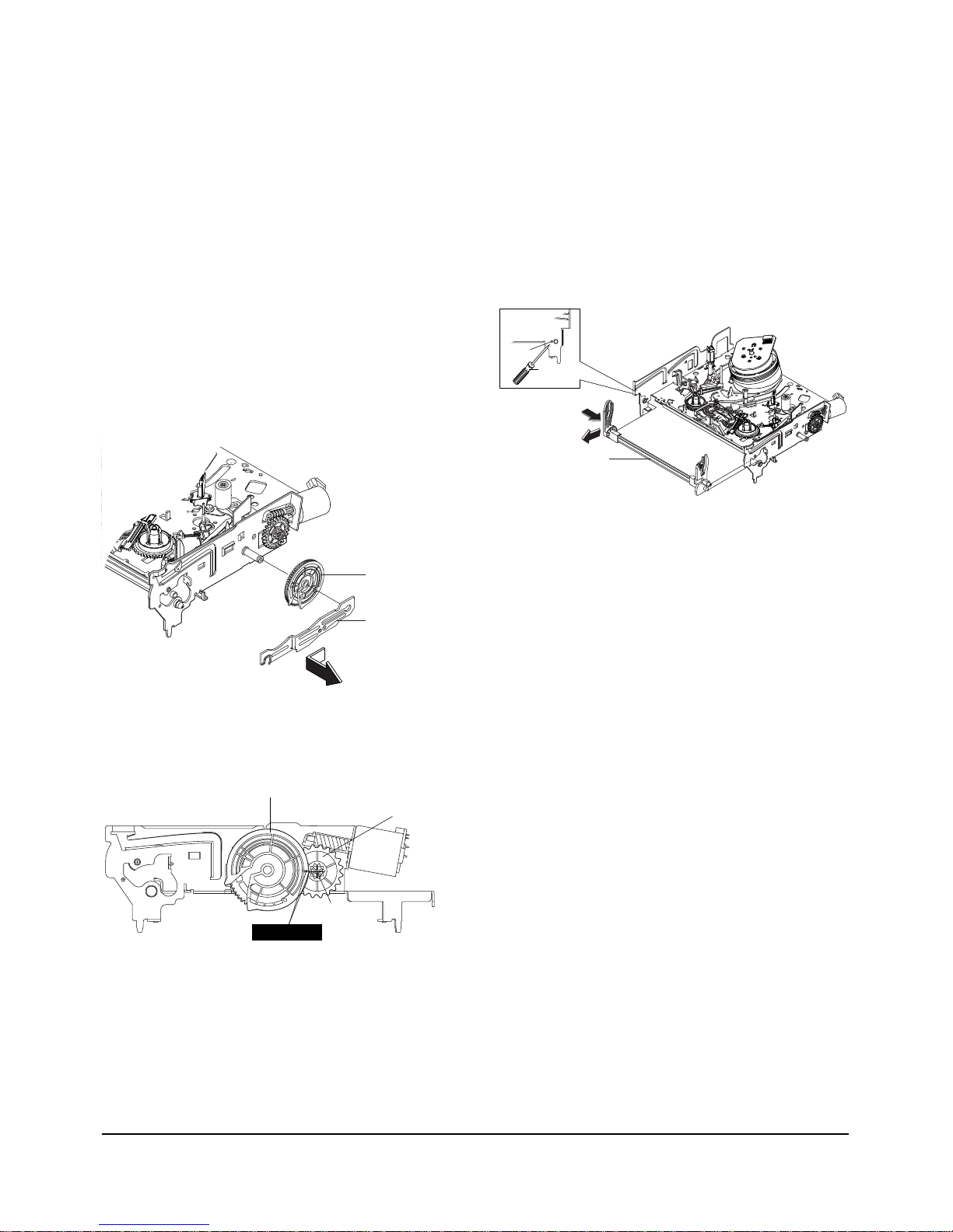
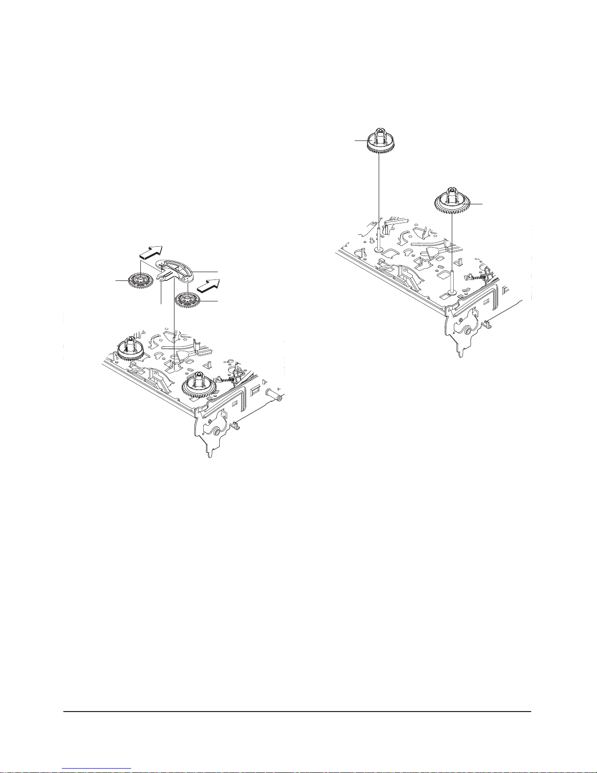
3-2-3 Slider FL Drive, Gear FL Cam Removal
1) Pull the Slider FL Drive Πto the front direction.
2) Remove the Slider FL Drive Πin the direction of
arrow. (Refer to Fig. 3-6)
3) Remove the Gear FL cam ´.
Note : When reinstalling be sure to reassemble Slider
FL drive Πafter you insert the Boss of Lever FL
ARM-R in Groove of Slider Fl drive Œ.
Assembly : Align the Gear FL Cam Πwith the Gear
worm wheel Post as shown drawing.
(Refer to Timing point)
ΠSLIDER FL DRIVE
´ GEAR FL CAM
Fig. 3-6 Slider FL Drive Removal
ΠLEVER FL ARM ASS`Y
"C"
"B"
PIN
HOLE "A"
Fig. 3-8 Lever FL Arm Ass’y Removal
3-6
Samsung Electronics
Disassembly and Reassembly
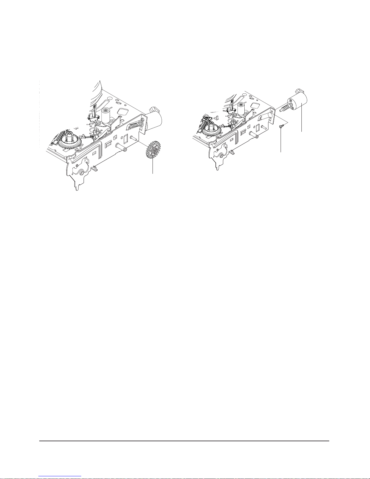
3-2-5 Gear Worm Wheel Removal
1) Remove the Gear Worm wheel Œ.
ΠGEAR WORM WHEEL
Fig. 3-9 Gear Worm Wheel Removal
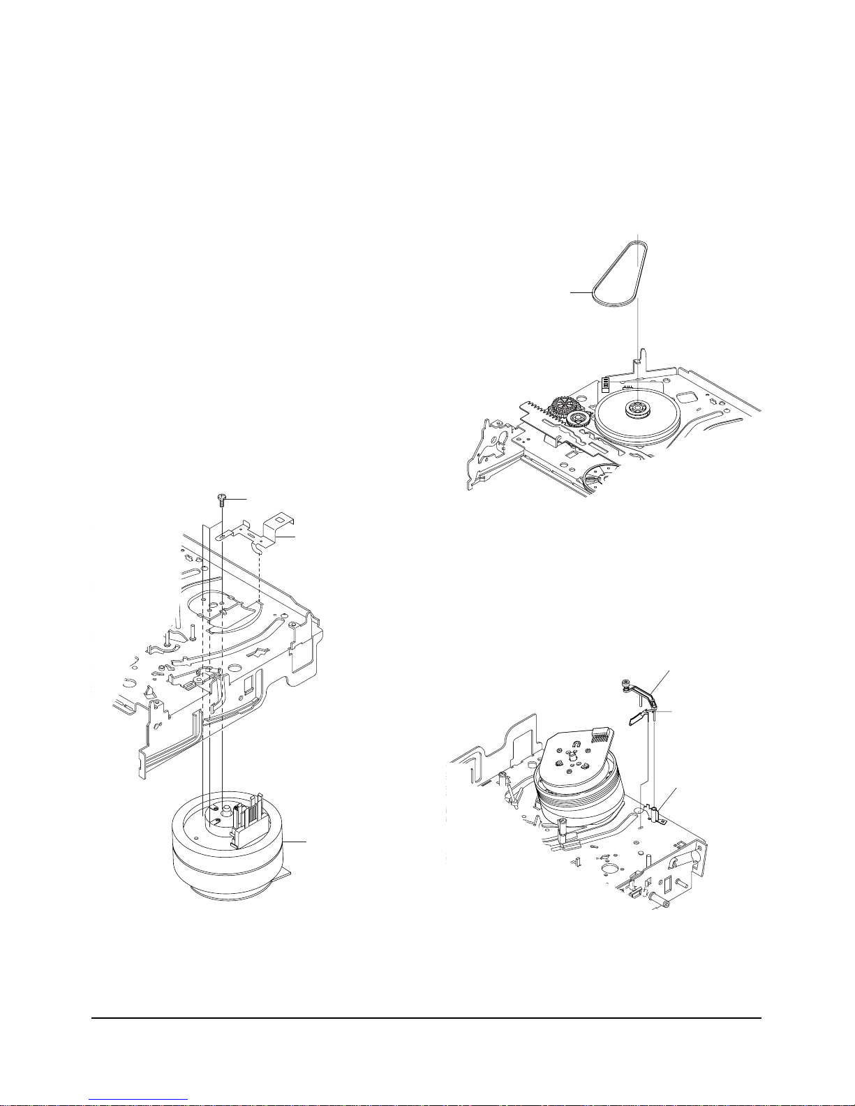
3-2-6 Motor Loading Ass’y Removal
1) Remove the screw Œ.
2) Remove the Motor Loading Ass’y ´.
´ MOTOR LOADING ASS`Y
ΠSCREW
Fig. 3-10 Motor Loading Ass’y Removal
Disassembly and Reassembly
Samsung Electronics
3-7
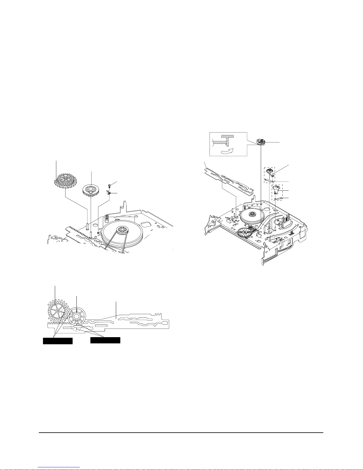
3-2-7 Bracket Gear, Gear Joint 2, 1 Removal
1) Remove the SCREW Œ.
2) Remove the Bracket Gear ´.
3) Remove the Gear Joint 2 ˇ.
4) Remove the Gear Joint 1 ¨.
Assembly :
1) Be sure to align dot mark of Gear Joint 1
Œ
with
dot mark of Gear Joint 2 ´ as shown Fig 3-12.
(Refer to Timing point1)
2) Confirm the Timing Point 2 of the Gear Joint 2 ´
and Slider Cam ˇ.
ΠSCREW
´ BRAKET GEAR
¨ GEAR JOINT 1
ˇ GEAR JOINT 2
3-2-8 Gear Loading Drive, Slider Cam,
Lever Load S, T Ass’y Removal
1) Remove the Belt Pulley. (Refer to Fig. 3-30)
2) Remove the Gear Loading Drive Πafter releasing
Hook [A] in the direction arrow as shown in detail
drawing.
3) Remove the Slider Cam ´.
4) Remove the Lever Load ˇ, Link Load ˆ & Lever
Load ¨, Link Load Ø.
ΠGEAR LOADING DRIVE
ˆ LINK LOAD S
ˇ LEVER LOAD S
¨ LEVER LOAD T
Ø LINK LOAD T
´ SLIDE CAM
HOOK(A)
Fig. 3-11 Bracket Gear, Gear Joint 1,2 Removal
ΠGEAR JOINT1
´ GEAR JOINT2
ˇ SLIDER CAM
TIMING POINT 1
TIMING POINT 2
Fig. 3-12 Gear Joint 1,2 Assembly
Fig. 3-13 Gear Loading Drive, Slider Cam,
Lever T, S Load Ass’y Removal

3-8
Samsung Electronics
Disassembly and Reassembly
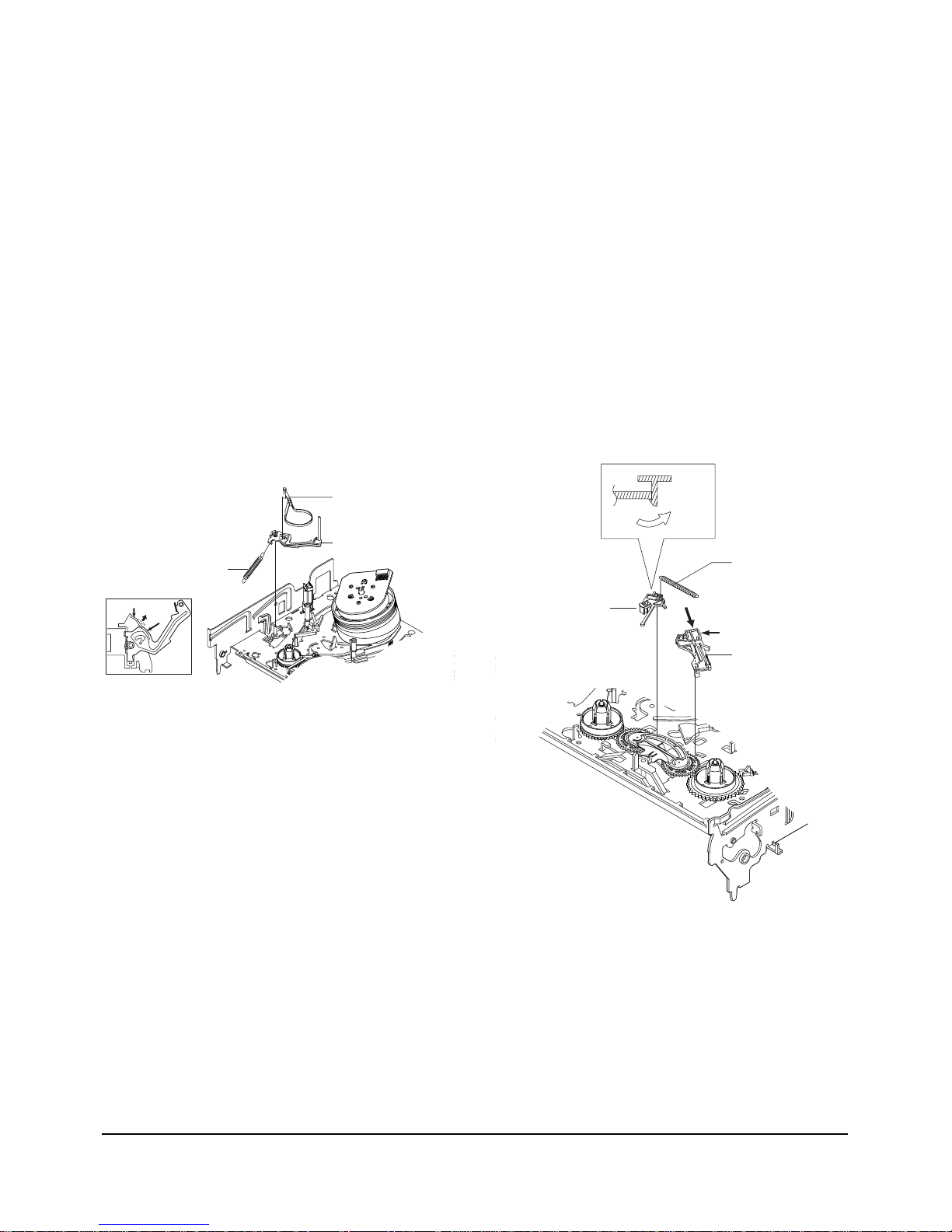
3-2-9 Gear Loading Drive, Slider Cam,
Lever Load S, T Ass’y Assembly
1) When reinstalling, be sure to align dot of Lever
Load T Ass'y
Œ
with dot of Lever Load S Ass'y ´
as shown in drawing, (Refer to Timing Point 1).
2) Insert the Pin A,B,C,D into the Slider Cam ˇhole,
3) Be sure to align dot of Lever Load T Πand dot of
Gear Loading Drive ¨, (Refer to Timing Point 2).
4) Aline dot of Gear Loading drive ¨ with mark of
Slider Cam ˇ as shown in drawing(Refer to
Timing Point 3).
´ LEVER LOAD S
Œ
LEVER LOAD T
LEVER LOAD S
LEVER LOAD T
PIN A
PIN C
PIN B
PIN D
ˇ SLIDER CAM
TIMING POINT 2
TIMING POINT 1
TIMING POINT 3
3-2-10 Lever Pinch Drive,
Lever Tension Drive Removal
1) Remove the Lever Pinch Drive Œ, Lever Tension
Drive ´.
ΠLEVER PINCH DRIVE
´ LEVER TENSION DRIVE
Fig. 3-14 Gear Loading Drive, Slider Cam,
Lever Load S, T Ass’y Assembly
Fig. 3-15 Lever Pinch Drive,
Lever Tension Drive Removal
Disassembly and Reassembly
Samsung Electronics
3-9
3-2-11 Lever Tension Ass’y,
Band Brake Ass’y Removal
1) Remove the Lever Brake S Ass'y (Refer to Fig 3-17).
2) Remove the Spring Tension Lever Œ.
3) Rotate stopper of Main Base in the direction of
arrow “A”.
4) Lift the Lever Tension Ass'y ´ & Band brake
Ass'y ˇ.
Note :
1) When replacing the Lever Tension Ass'y ´, be sure
to apply Grease on the post,
2) Take care not to touch stain on the felt side, and not
to be folder and broken Band brake Ass'y
3) After Lever Tension Ass'y seated, Rotate stopper of
Main Base to the Mark[B].
ΠSPRING TENTION LEVER
STOPPER
MARK[B]
"A"
´ LEVER TENTION ASS`Y
ˇ BAND BRAKE ASS`Y
3-2
-12 Lever Brake S, T Ass’y
Removal
1) Release the Hook [A] and the Hook [B], [C] in the
direction of arrow as shown in Fig 3-17.
2) Lift the Lever S, T Brake Ass'y Œ, ´ with spring
brake ˇ.
Assembly :
1)Assembly the Lever S Brake Ass'y Πon the Main
Base.
2)Assembly the Lever T Brake Ass'y ´ with spring
brake ˇ.
Note : Take extreme care not to be folded and
transformed Spring Brake at removing or reinstalling.
ΠLEVER S BRAKE ASS`Y
´ LEVER T BRAKE ASS`Y
ˇ SPRING BRAKE
HOOK(B)
HOOK(C)
HOOK(A)
Fig. 3-16 Lever Tension Ass’y,
Band Brake Ass’y Removal
Fig. 3-17 Lever Brake S, T Ass’y Removal
3-10
Samsung Electronics
Disassembly and Reassembly
ΠDISK S REEL
´ DISK T REEL
Fig. 3-19 Disk S, T Reel Removal
3-2-13 Gear Idle Ass’y Removal
1) Push the Lever Idle Πin the direction of arrow
“A”, “B”.
2) Lift the Lever Idle Œ.
Assembly :
1) Apply oil in two Bosses of Lever Idle Œ.
2) Assemble the Gear Idle ´ with the Lever Idle Œ.
Note : When replacing the Gear Idle ´, be sure to
add oil in the boss of Lever Idle Œ.
3-2-14 Disk S, T Reel Removal
1) Lift the Disk S, T Reel Œ, ´.
´ GEAR IDLE
´ GEAR IDLE
ΠLEVER IDLE
"A"
HOOK "C"
"B"
Fig. 3-18 Gear Idle Ass’y Removal
Disassembly and Reassembly
Samsung Electronics
3-11
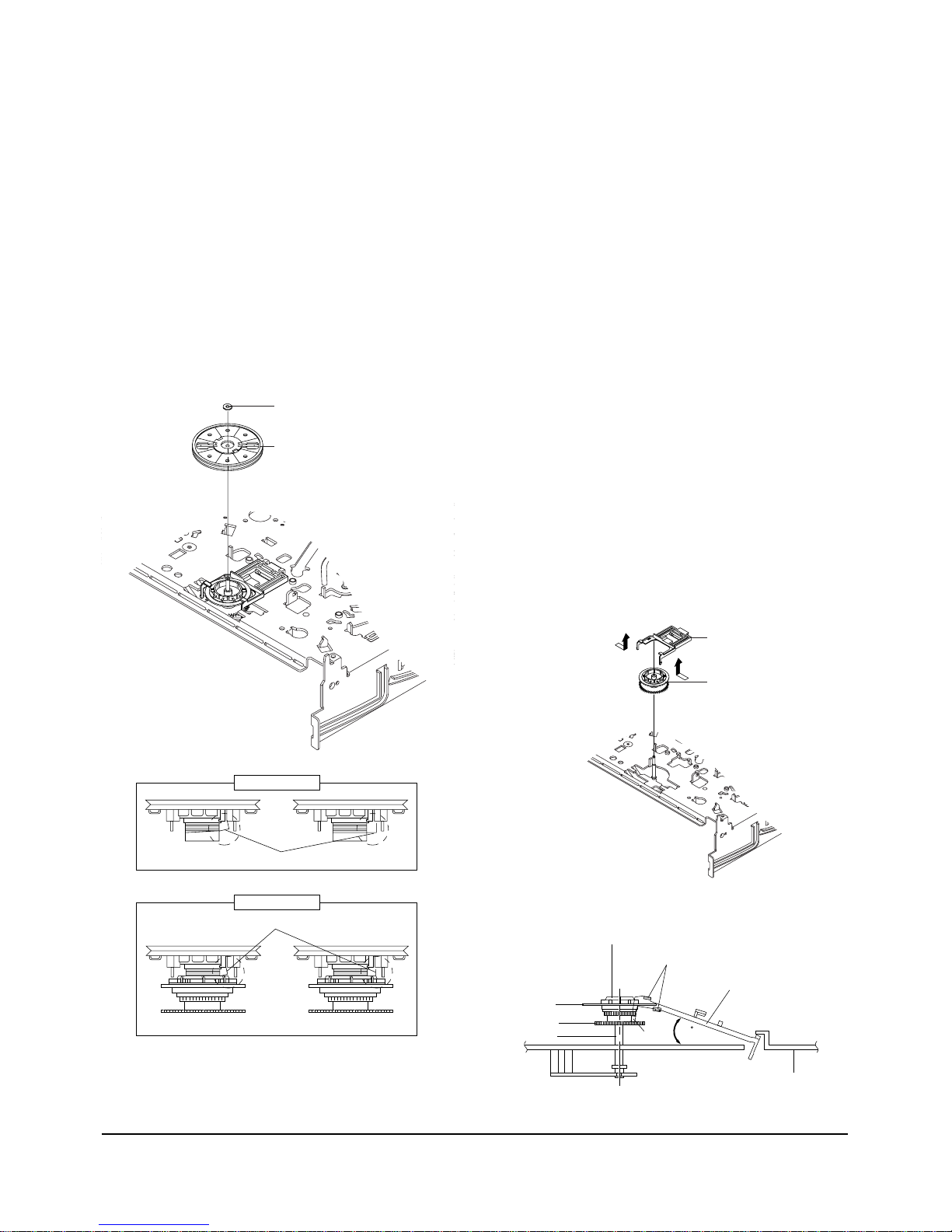
3-2-15 Holder Clutch Ass’y Removal
1) Remove the Washer Slit Œ.
2) Lift the Holder Clutch Ass’y ´.
Note : When you reinstall Holder Clutch Ass'y
1) Check the condition of spring as shown in detail A.
2) Don't push Holder Clutch Ass'y down with excessive force Just insert Holder Clutch Ass'y into post
center with dead force and Rotate it smoothly.
Be sure to confirm that spring is in the slit of Gear
Center Ass'y as shown in detail B.
ΠWASHER SLIT
´ HOLDER CLUTCH ASS`Y
<BAD>
<GOOD>
<BAD>
<GOOD>
SPRING
SPRING
DETAIL A
DETAIL B
Fig. 3-20 Holder Clutch Ass’y Removal
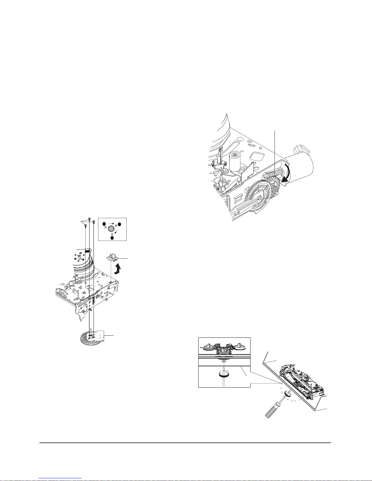
3-2-16 Lever Up Down Ass’y, Gear Center
Ass’y Removal
1)
Remove the 2 hooks in the direction of arrow as
shown Fig. 3-21 and lift the Lever Up Down Ass’y
Œ.
2) Lift the Gear Center Ass’y ´.
Assembly :
1) Insert the Lever Up Down Ass'y Πin the rectangular holes on Main Base as shown in Fig 3-22.
2) Lift the Lever Up Down Ass'y Œ about 35°.
(Refer to Fig 3-22)
3) Insert Ring of the Gear Center Ass'y ´ in the
Guide of the Lever Up Down Ass'y Œ.
4) Insert the Gear Center Ass'y ´ in the post on
Main Base.
5) Push down the Lever Up Down Ass'y Πfor
locking of the Hook.
Note :
1) Take care not to separate and sentence does not
mark sense.
2) Be sure to confirm that Ring of the Gear Center
Ass'y ´ is in the Guide of the Lever Up Down
Ass'y Πafter finishing assembly of Lever Up
Down Ass'y Œ and Gear Center Ass'y ´.
ΠLEVER UP DOWN ASS`Y
´ GEAR CENTER ASS`Y
MAIN BASE
LEVER UP DOWN ASS'Y
GUIDE
GEAR CENTER ASS'Y
RING
GEAR
POST
HOOK
35
Fig. 3-21 Lever Up Down Ass’y Removal
Fig. 3-22 Lever Up Down Ass’y Removal
3-12
Samsung Electronics
Disassembly and Reassembly
ΠGUIDE CASSETTE DOOR
HOOK [A]
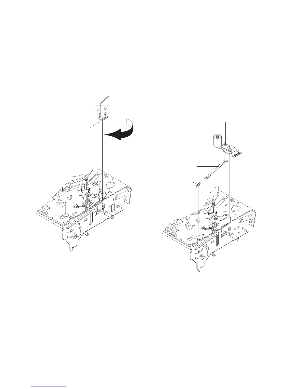
3-2-18 Lever Unit Pinch Ass’y, Plate Joint,
Spring Pinch Drive Removal
1) Lift the Unit Pinch Ass’y Œ.
2) Remove the Plate Joint ´ from Lever Pinch Drive.
3) Remove the Spring Pinch Drive ˇ.
Note :
1) Take extreme care not to touch the grease on the
Roller Pinch.
2) When reinstalling, be sure to apply grease on the
post pinch roller.
ˇ SPRING PINCH DRIVE
ΠLEVER UNIT PINCH ASS`Y
´ PLATE JOINT
Fig. 3-23 Guide Cassette Door Removal
Fig. 3-24 Lever Unit Pinch Ass’y, Plate Joint,
Spring Pinch Drive Removal
3-2-17 Guide Cassette Door Removal
1) Lift the Hook [A].
2) Rotate the Guide Cassette Door Πin the direction
of arrow.
Note : After reinstalling the Guide Cassette Door Œ
sure the Hook [A].
Disassembly and Reassembly
Samsung Electronics
3-13
3-2-19 Lever #9 Guide Ass’y Removal
1) Remove the Spring #9 Guide Œ.
2) Lift the Spring #9 Guide Ass’y ´ in the direction
of arrow “A”.
Note :
1) Take extreme care not to get grease on the tape
Guide Post.
2) After reinstalling, check the bottom side of the Post
#9 Guide to the top side of Main Base.
ΠSPRING #9 GUIDE
´ LEVER #9 GUIDE ASS`Y
"A"
"B"
Fig. 3-25 Lever #9 Guide Ass’y Removal
3-2-20 FE Head Removal
1) Remove the screw Œ.
2) Lift the FE Head ´.
ΠFE HEAD
Fig. 3-26 FE Head Removal
3-14
Samsung Electronics
Disassembly and Reassembly
3-2-21 ACE Head Removal
1) Pull out the FPC from connector of ACE Head
Ass’y ´.
2) Remove the screw Œ.
3) Lift the ACE Head Ass’y ´.
ΠSCREW
´ HEAD ACE ASS`Y
3-2-22 Slider S, T Ass’y Removal
1) Move the Slider S, T Ass’y Œ, ´ to slot, and then
lift it to remove. (Refer to arrow)
ΠSLIDER S ASS`Y
´ SLIDER T ASS`Y
Fig. 3-27 ACE Head Removal
Fig. 3-28 Slider S, T Ass’y Removal
Disassembly and Reassembly
Samsung Electronics
3-15
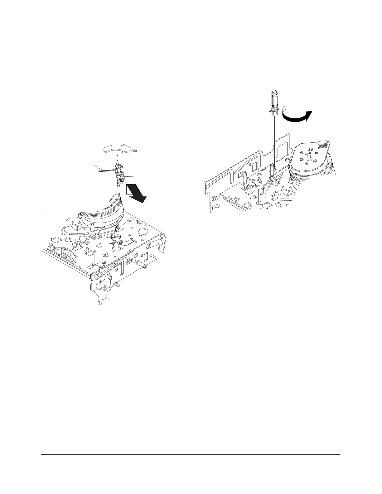
3-2-23
Plate Ground Deck, Cylinder Ass’y Removal
1) Remove the 3 Screws Œ.
2) Lift the Plate Ground Deck ´.
3) Lift the Cylinder Ass’y ˇ.
Assembly :
1) Match the 3 holes in the bottom of Cylinder ass'y
ˇ to the 3 holes of Main Base as attending not to
drop or knock the Cylinder ass'y ˇ.
2) Tighten the 1 Screw Œ.
3) Match the Plate Ground Deck ´ to the Hole of
Base Main.
4) Tighten the other 2 Screws Œ.
Note :
1) Take care not to touch the Cylinder Ass'y ˇ and
the tape guide post at reinstalling.
2) When reinstalling, Don't push down too much on
Screw Driver.
Π3 SCREWS
´ PLATE GROUND DECK
ˇ CYLINDER ASS'Y
Fig. 3-29 Plate Ground Deck, Cylinder Ass’y Removal
3-2-24 Belt Pulley Removal
1) Remove the Belt Pulley Œ.
Note : Take extreme care not to get grease on Belt
Pulley Πat assembling or reassembling.
ΠBELT PULLEY
Fig. 3-30 Belt Pulley Removal
3-2-25 Level Head Cleaner Ass’y Removal
(Optional)
1) Release the Hook Œ.
2) Lift the Lever Head Cleaner Ass’y
´.
ΠHOOK
´ LEVER HEAD CLEANER ASS'Y
SLEEVE-HEAD CLEANER
Fig. 3-31 Level Head Cleaner Ass’y Removal
3-16
Samsung Electronics
Disassembly and Reassembly
3-2-26 Damper Capstan, Motor Capstan Ass’y
Removal
1) Remove the Damper Capstan Πin the direction
of arrow.
2) Remove the 3 Screws ´.
3) Remove the Motor Capstan Ass’y ˇ.
Assembly :
1) Match the 3 holes of Motor Capstan Ass’y ˇ to the
3 holes of Main Base. Be careful not to drop or
knock the Motor Capstan Ass'y ˇ.
2) Tighten the 3 Screws ´ in the direction of arrow
as shown detail drawing.
3) Assemble the Damper Capstan Œ.
Note : After tightening screws, check if there is gap
between the head of screws and the top side of Main
Base. There should have no gap between the head of
screws and the top side of Main Base.
After reinstalling, adjusting the tape transport
system again.
B
C
A
´ 3 SCREWS
ΠDAMPER CAPSTAN
ˇ MOTOR CAPSTAN ASS'Y
3-2-27 How to Eject the Cassette Tape
(If the unit does not operate on condition that is
inserted into housing ass’y)
1) Turn the Gear worm Πclockwise with screw
driver.(Refer to arrow)
(Other method : Remove the Screw of Motor Load
Ass'y, Separate the Motor Load Ass'y)
ΠGEAR WORM
Fig. 3-32 Damper Capstan,Motor Capstan Ass’y Removal
Fig. 3-33 How to Eject the Cassette Tape
2) When Slider S,T are approched in the position of
unloading, rotate holder Clutch counterclockwise
after inserting screw driver in the hole of frame's
bottom in order to wind the unwinded tape.
(Refer to Fig.3-34)
(If you rotate Gear Worm Πcontinuously when
tape is in state of unwinding, you may cause a
tape contamination by grease and tape damage.
Be sure to wind the unwinded tape in the state of
set horizently.)
3) Rotate Gear Worm Πclockwise using screw driver
again up to the state of eject mode and then pick
out the tape.(Refer to Fig.3-33)
FRAME
Fig. 3-34
Disassembly and Reassembly
Samsung Electronics
3-17
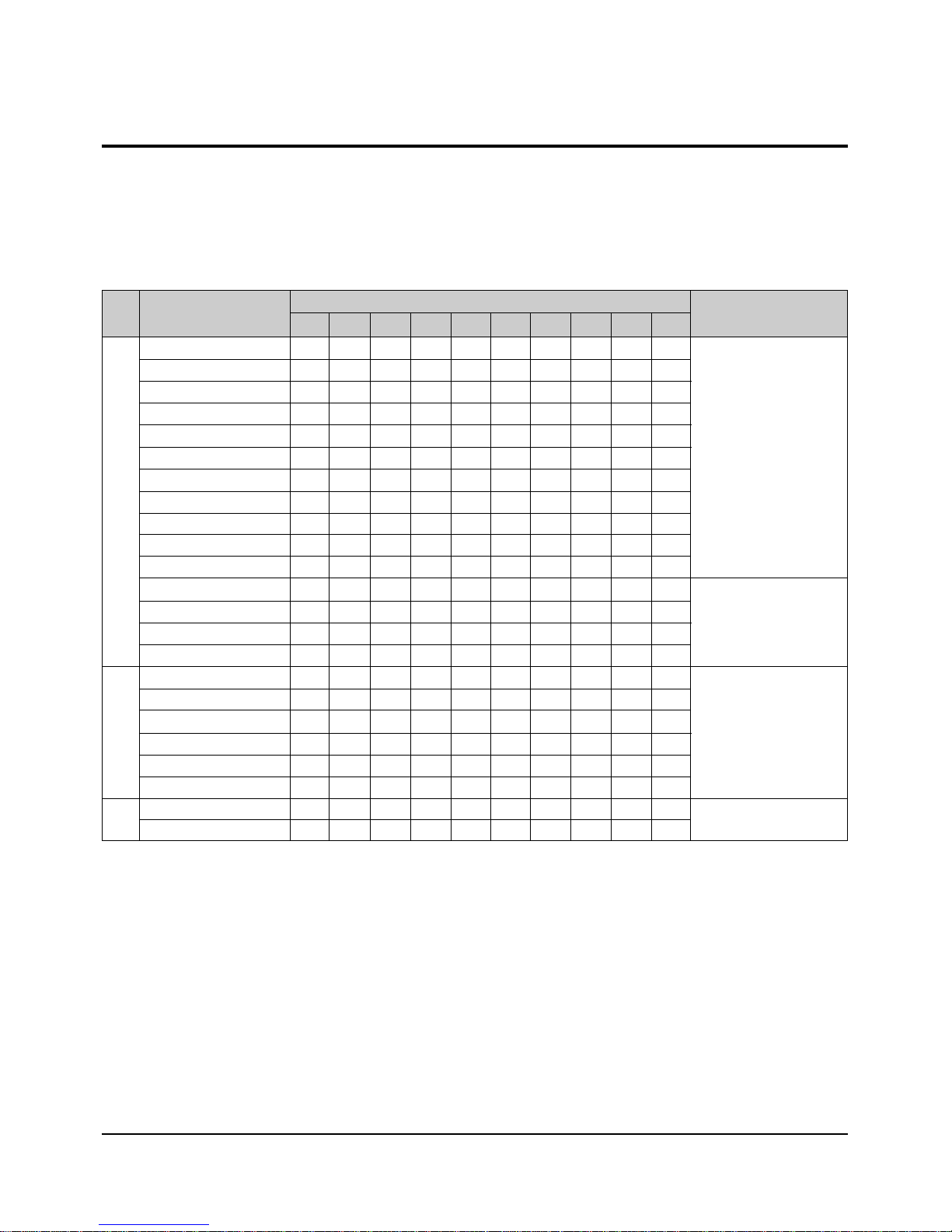
3-3 The table of clearing, Lubrication and replacement time about principal parts
1) The replacement time of parts is not life of parts.
2) The table 1-1 is that the VCR Set is in normal condition (normal temperature, normal humidity).
The checking period may be changed owing to the condition of use, runtime and environmental conditions.
3) Life of the Cylinder Ass’y is depend on the condition of use.
4) See exploded view for location of each parts.
<Table 1-1>
∆ : Cleaning O : Check and replacement in necessary : Add Oil
T
A
PE
P
A
T
H
S
Y
S
T
E
M
D
R
I
V
I
N
G
* Parts Name
Checking Period
Remark
500 1000 1500 2000 2500 3000 3500 4000 4500 5000
POST TENSION ∆∆∆∆∆∆∆∆∆∆
SLANT POST S, T ∆∆∆∆∆∆∆∆∆∆
#8 GUIDE SHAFT ∆∆∆∆∆∆∆∆∆∆
CAPSTAN SHAFT ∆∆∆∆∆∆∆∆∆∆
#9 GUIDE POST ∆∆∆∆∆∆∆∆∆∆
#3 GUIDE POST ∆∆∆∆∆∆∆∆∆∆
GUIDE ROLLER S, T ∆∆∆ OOOO OOO
CYLINDER ASS’Y ∆ OOOOOOO OO
FE HEAD ∆∆∆ OOOO OOO
ACE HEAD ∆ OO OOOOOOO
PINCH ROLLER ∆ OO OOOOOOO
POST REEL S, T
SLEEVE TENSION
POST CENTER
LEVER IDLE BOSS (2Point)
CAPSTAN MOTOR PULLEY
∆∆∆ ∆∆ OOOOO
BELT PULLEY O O O O O O O
HOLDER CLUTCH ASS’Y
∆ OO OOOOOOO
GEAR CENTER ASS’Y OOOOOOOOO
GEAR IDLE (2Point) O O O O O O O O O
LOADING MOTOR O O O O O O O O O
BAND BRAKE ASS’Y OOOOOOOOO
BRAKE T ASS’Y OOOOOOOOO
S
Y
S
T
E
M
- Periodic time of applying oil (Apply
oil after cleaning)
- The excessive applying oil may be
the cause of
malfunction.
- To clean the parts, use patch and
alcohol (solvent).
- After cleaning, use the video tape
after alcohol is gone away completely.
- We recommend to use oil [EP-50]
or solvent.
- One or two drops of oil should be
applied after
cleaning with alcohol.
B
R
A
K
E
S
Y
S
T
E
M
3-18
Samsung Electronics
Disassembly and Reassembly
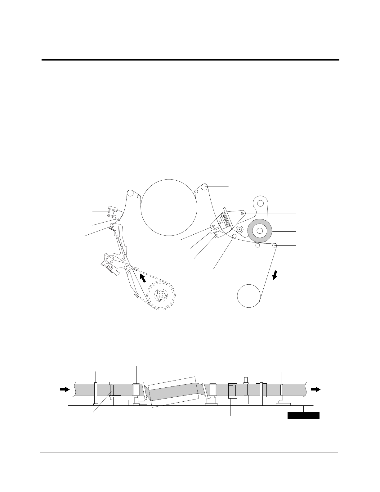
Fig. 3-4-1 Location of Tape Transport Adjustment
Fig. 3-4-2 Tape Travel Diagram
CYLINDER ASS'Y
TAKE UP REEL DISK
#8 GUIDE POST
#9 GUIDE POST
SUPPLY REEL DISK
CAPSTAN
PINCH ROLLER
GUIDE ROLLER "T"
GUIDE ROLLER "S"
FULL ERASE HEAD
#3 GUIDE POST
TENSION POST
HEIGHT SCREW
TILT SCREW
X - POSITION
ADJUST SILT
AZIMUTH SCREW
POST TENSION
MAIN BASE
FE HEAD CYLINDER ASS'Y
PINCH ROLLER
GUIDE ROLLER "S" GUIDE ROLLER "T"
#8 GUIDE POST #9 GUIDE POST
CAPSTAN SHAFT
ACE HEAD
#3 GUIDE POST
3-4 Tape Transport System and Adjustment Locations
The tape transport system has been adjusted precisely in the factory. Alignment is not necessary except for the
following :
1) Noise observed on the screen.
2) Tape damage.
3) Parts replacement in the tape transport system.
Lower flange height of tape guide is used as the reference for the transport adjustment.
To maintain the height of the tape guide and prevent damage, do not apply excessive force onto the main base.
Disassembly and Reassembly
Samsung Electronics
3-19
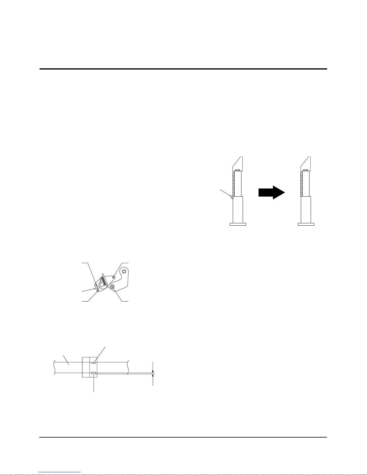
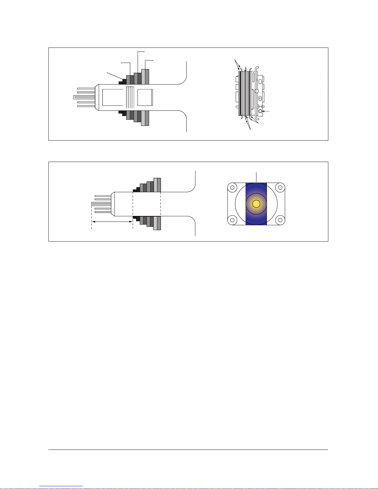
3-5-1(a) ACE HEAD HEIGHT ADJUSTMENT
1) Run the alignment tape (Color bar) in the playback
mode.
2) Observe surface of the audio head using a dental
mirror.
3) Turn screw (C) clockwise or counterclockwise until
the gap of lower tape edge and the lower edge of
the control head is about 0.25mm.
(Refer to Fig. 3-5-1 and 3-5-2)
Fig. 3-5-1 Location of ACE Head Adjustment Screw
Fig. 3-5-2 ACE Head Height Adjustment
SCREW (A)
TLIT ADJUST
X-POSITION
ADJUSTING SLIT
SCREW (C)
HEIGHT ADJUST
SCREW (D)
X-POSITION LOCKING
SCREW (B)
AZIMUTH ADJUST
0 ~ 0 .25 mm
AUDIO HEAD
VIDEO HEAD
CONTROL HEAD
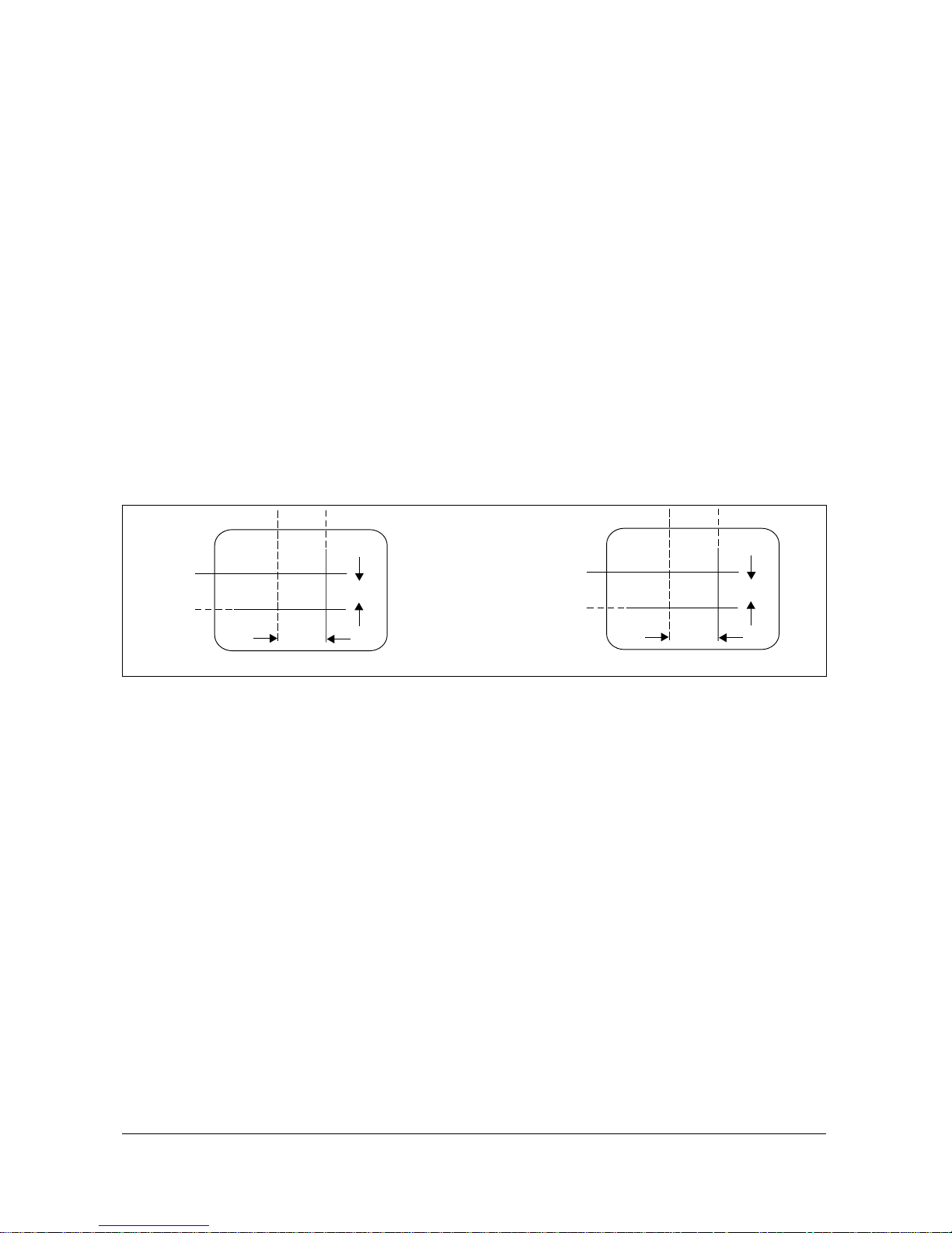
3-5-1(b) ACE HEAD TILT ADJUSTMENT
1) Playback a blank tape and observe the position of
the tape at the lower flange of tape guide.
2) Confirm that there is no curl or wrinkle at the
lower flange of tape guide as shown in
Fig. 3-5-3 (B).
3) If a curl or wrinkle of the tape occurs, slightly
turn
the screw (A) tilt adjust on the ACE head ass’y.
4) Reconfirm the ACE head height.
Fig. 3-5-3 Tape Guide Check
3-5-1(c) AUDIO AZIMUTH ADJUSTMENT
1) Load alignment tape (Mono scope) and playback
the NTSC : 7KHz (PAL : 6KHz) signal.
2) Connect channel-1 scope probe to audio output
test point.
3) Adjust screw (B) to achieve maximum audio level.
(See Fig. 3-5-1)
4-5-1(d) ACE HEAD POSITION (X-POINT)
ADJUSTMENT
1) See “2. Alignment and Adjustment” for ACE Head
position (X-Point) adjustment.
(A) (B)
(BAD)
WRINKLE
(GOOD)
3-5 Tape Transport System Adjustment
When parts are replaced, perform the required
adjustments by referring to procedures for the tape
transport system. If there are any changes to the tape
path, first run a T-120 tape and make sure excessive
tape wrinkle does not occur at the tape guides.
1) If tape wrinkle is observed at the guide roller S, T,
turn the guide roller S, T until wrinkle disappears.
2) If the tape wrinkle is still observed at the tape
guide, perform the tilt adjustment of the ACE head.
(See “2. Alignment and Adjustment” of the
Service Manual for Test Point Locations.)
3-5-1 ACE Head Assembly Adjustment
3-20
Samsung Electronics
Disassembly and Reassembly
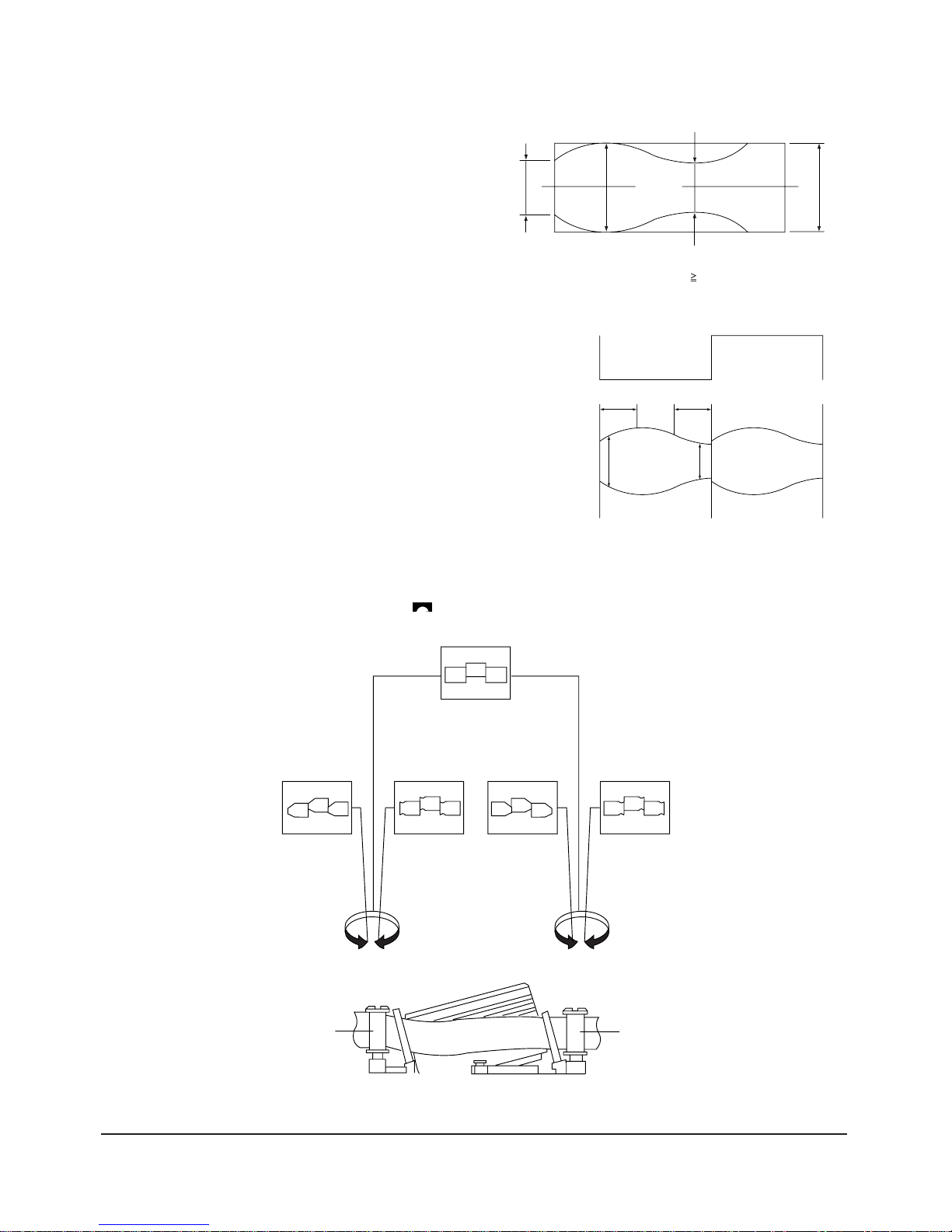
3-5-2 Linearity adjustment
(Guide roller S, T adjustment)
1)
Playback the Mono Scope alignment tape (SP mode).
2) Observe the video envelope signal on an oscilloscope (triggered by the video switching pulse).
3) Make sure the video envelope waveform (at its
minimum) meets the specification shown in
Fig. 3-5-4.
If it does not, adjust as follows :
Note :
a=Maximum output of the video RF envelope.
b=Minimum output of the video RF envelope at the
entrance side.
c=Minimum output of the video RF envelope at the
center point.
d=Maximum output of the video RF envelope at the
exit side.
4) If the section Ain Fig. 3-5-5 does not meet the
speci-fication, adjust the guide roller S up or
down.
5) If the section B in Fig. 3-5-5 does not meet the
speci-fication, adjust the guide roller T up or down.
Fig. 3-5-4 Envelope Waveform Adjustment
a
a b c d
c,b,d/a
63%
b
c
d
Fig. 3-5-5 Adjustment Points
AB
A
B
H'D SWITCHING
PULSE
ENVELOPE
6) Play back the Mono Scope alignment tape (SP mode).
7) Connect an oscilloscope CH-1 to the Envelope and CH-2 to the H’D SW Pulse for triggering.
8)
Turn the guide roller heads with a flat head ( ) driver to obtain a flat video RF envelope as shown in Fig. 3-8.
Fig. 3-5-6 Guide Roller S, T Height Adjustment
IDEAL ENVELOPE
S HEIGHT TOO HIGH
S HEIGHT TOO LOW
T HEIGHT TOO HIGH
T HEIGHT TOO LOW
GUIDE ROLLER S
GUIDE ROLLER T
Disassembly and Reassembly
Samsung Electronics
3-21
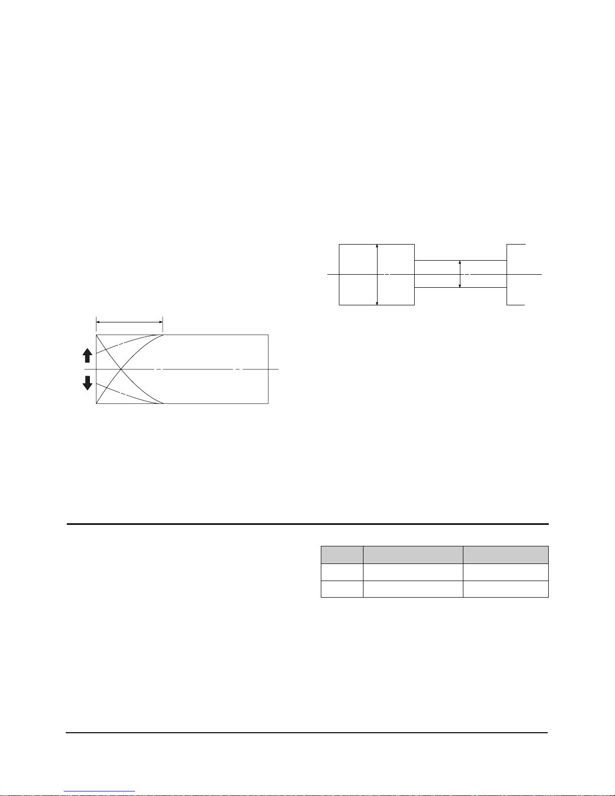
3-5-3 Check Transitional Operation from
RPS to Play
Check transition from RPS mode to play mode :
Using a pre-recorded SP tape, make sure the entry
side of envelope comes to an appropriate steady state
within 3 seconds (as shown in Fig. 3-5-7).
If the envelope waveform does not reach specified
peak-to peak amplitude within 3 seconds, adjust as
follows :
1) Make sure there is no gap between the supply
roller lower flange and the tape.
If there is a gap, adjust the supply guide roller
again.
2) Change operation mode from the RPS to the play
mode (again) and make sure the entry side of
envelope rises within 3 second.
ENTRANCE SIDE ENVELOPE
Fig. 3-5-7 Video Envelope Rising when Operation mode Changes
from RPS to Play Mode
3-5-4 Envelope Check
1) Make recordings on T-120 (E-120) and T-160
(E-180) tape.
Make sure the playback output envelope meets the
specification as shown in Fig. 3-5-8.
2) Play back a self recorded tape (recording made on
the unit using with T-120 (E-120).
The video envelope should meet the specification
as shown in Fig. 3-5-8.
In SP mode, (A) should equal (B).
If the head gap is wide, upper cylinder should be
checked.
A
B
Fig. 3-5-8 Envelope Output and Output Level
3-5-5 Tape Wrinkle Check
1) Run the T-160 (E-180) tape in the playback, FPS,
RPS and Pause modes and observe tape wrinkle at
each guide.
2) If excessive tape wrinkle is observed, perform the
following adjustments in Playback mode :
Tape wrinkle at the guide roller S, T section :
Linearity adjustment.
Tape wrinkle at tape guide flange :
ACE head assembly coarse adjustment.
3-6 Reel Torque
1) The rotation of the capstan motor causes the
Holder Clutch Ass’y to rotate through the Belt
Pulley.
2) The spring wrap PLAY/REV of holder clutch ass’y
drives the disk reel S, T through gear idle by rotation of gear center ass’y.
3) Brake is operated by slider cam at FF/REW mode.
4) Transportation of accurate driving force is done by
gears. (Gear Center Ass’y)
Note : If the spec. does not meet the followings specifications, replace the holder clutch ass’y and then
recheck.
MODE TORQUE g/cm GAUGE
PB 42 ± 11
Cassette Torquemeter
RPS 145 ± 30
Cassette Torquemeter
<Table 2-1>

4-2 Factory (“Service”) Mode
Alignment and Adjustments (Electrical)
Samsung Electronics 4-1
4. Alignment and Adjustments (Electrical)
4-1 Preadjustment
4-1-1 Factory Mode
1. Do not attempt these adjustments in the Video
Mode.
2. The Factory Mode adjustments are necessary
when either the EEPROM (IC902) or the CRT
is replaced.
3. Do not tamper with the “Adjustment” screen
of the Factory Mode menu. This screen is
intended only for factory use.
4-1-2 When EEPROM (IC902S) Is Replaced
1. When IC902 is replaced all adjustment data
revert to initial values. It is necessary to reprogram this data.
2. After IC902 is replaced, warm up the TV for
10 seconds.
4-1-3 When CRT Is Replaced
Make the following adjustments after setting up
purity and convergence:
White Balance
Sub-Brightness
Vertical Center
Vertical Size
Horizontal Size
4-2-1 Procedure for the “Adjustment” Mode
1. This mode uses the standard remote control.
The Service Mode is activated by: (1) pressing
the “FACTORY” service key on the local-keyboard, or (2) by entering the following remotecontrol sequence (within 2 seconds):
STAND-BY →DISPLAY →MENU→ MUTE→
POWER ON
2. The “SERVICE (FACTORY)” message will be
displayed. The Service Mode has three components: Adjustment, Option and Reset.
3. Access the Adjustment Mode by pressing the
“VOLUME” keys ( Up or Down). The adjustment parameters are listed in the accompanying table, and selected by pressing the CHANNEL keys (▲,▼).
4. Selection sequences for the
PAL/SECAM B/G, L/systems:
down or up key:
AGC>TXP>AFW>SBT>SCT>SCR>STT>RG>
GG>BG>TCT>SC>SL>PVS>PHS>NVS>
NHS>CDL>BKS
5. The VOLUME keys increase or decrease the
adjustment values, (stored in the
non-volatile memory) when Adjustment Mode
is cancelled.

Alignment and Adjustments (Electrical)
4-2 Samsung Electronics
4-2-2 Main Adjustment Parameters
OSD ABBREVIATION
AGC
XP
QSS
SBT
SCT
SCR
STT
RG
GG
BG
TCT
SC
SL
VA
PVS
PHS
NVS
NHS
CDL
SCL
PWL
OMD
BLR
BLB
AGC2T
PF
RP
YD
RANGE
63
7
1
23
23
13
13
63
63
63
1
63
63
63
63
63
63
63
15
3
15
63
63
63
31
3
3
15
INITIAL DATA
28
5
1
6
10
6
9
38
32
32
0
11
30
38
27
40
38
22
4
1
12
26
31
27
15
2
2
5
NOTE : PVS, PVA, PHS, NVS, NVA,NHS parameters must be aligned using both the 50 Hz and 60 Hz
vertical-field rates.
4-2-3 AGING Mode (Reference Only)
This pattern is used for pre-heating the CRT during manufacturing--it is accessed in the
factory by twice pressing the "FACTORY" key .
Even if the TV power is cut off, the Aging Mode is not cancelled.
The "AGING" marking is displayed on the screen.
The AGINGmode is cancelled by repressing the "FACTORY" key.

Alignment and Adjustments (Electrical)
Samsung Electronics 4-3
BYTE
1
2
3
4
5
6
7
8
9
ITEM
LANGUAGE
SYSTEM
TUNER
HELP MESSAGE
VCR HEAD
G-CODE
ATS OPTION
VPS/PDC
TTX
0
EUROPE/URSSIA
CF/CI/CW/CX/CB/CII
1/2
ON/OFF
2HD/2HDLP/4HD/HIFI
SHOWVIEW/VIDEO PLUS/NONE
ON/OFF
PDC/VPS/NONE
ON/OFF
4-3 Reset
BYTE
1
2
3
4
5
6
7
8
9
ITEM
Contrast
Bright
Sharpness
Color
Tint
Volume
Program Number
Color System
Sound System
3DB LNA
Panel Lock
Language
Clock
Timer
On Time
Sleep
PICTURE MODE
0
4-2-4 Option

Alignment and Adjustments (Electrical)
4-4 Samsung Electronics
4-4 Other Adjustments
4-4-1 General
1. Usually, a color TV needs only slight
touch-up adjustment upon installation.
Check the basic characteristics such as height,
horizontal and vertical sync and focus.
2. The picture should have good black and white
details. There should be no objectionable
color shading; if color shading is present,
perform the purity and convergence adjustments described below.
3. Use the specified test equipment or its
equivalent.
4. Correct impedance matching is essential.
5. Avoid overload. Excessive signal from a sweep
generator might overload the front-end of the
TV. When inserting signal markers, do not
allow the marker generator to distort test
results.
6. Connect the TV only to an AC power source
with voltage and frequency as specified on the
backcover nameplate.
7. Do not attempt to connect or disconnect any
wires while the TV is turned on. Make sure
that the power cord is disconnected before
replacing any parts.
8. To protect against shock hazard, use an
isolation transformer.
4-4-2 Automatic Degaussing
A degaussing coil is mounted around the
picture tube, so that external degaussing after
moving the TV should be unnecessary. But
the receiver must be properly degaussed upon
installation.
The degaussing coil operates for about 1
second after the power is switched ON. If the
set has been moved or turned in a different
direction, disconnect its AC power for at least
10 minutes.
If the chassis or parts of the cabinet become
magnetized, poor color purity will result. If
this happens, use an external degaussing coil.
Slowly move the degaussing coil around the
faceplate of the picture tube and the sides and
front of the receiver. Slowly withdraw the coil
to a distance of about 6 feet before removing
power.
4-4-3 High Voltage Check
CAUTION: There is no high voltage
adjustment on this chassis. The B+ power
supply must be set to +125 volts (Full color
bar input and normal picture level).
1. Connect a digital voltmeter to the second
anode of the picture tube.
2. Turn on the TV. Set the Brightness and
Contrast controls to minimum (zero beam
current).
3. The high voltage should not exceed 27.5KV.
4. Adjust the Brightness and contrast controls to
both extremes. Ensure that the high voltage
does not exceed 27.5KV under any conditions.

Alignment and Adjustments (Electrical)
Samsung Electronics 4-5
4-4-4 FOCUS Adjustment
1. Input a black and white signal.
2. Adjust the tuning control for the clearest picture.
3. Adjust the FOCUS control for well defined scanning lines in the center area of the screen.
4-4-5 Screen Adjustment
1. Turn to the ACTIVE channel.
2. Adjust the VR screen for a normal picture is (no blooming or flyback line).
3. Adjust the FOCUS control for well defined scanning lines in the center area of the screen.
4-4-6 Purity Adjustment
1. Warm up the receiver for at least 20 minutes.
2. Plug in the CRT deflection yoke and tighten the clamp screw.
3. Plug the convergence yoke into the CRT and set in as shown in Fig. 4-1.
4. Input a black and white signal.
5. Fully demagnetize the receive by applying an external degaussing coil.
6. Turn the CONTRAST and BRIGHTNESS controls to maximum.
7. Loosen the clamp screw holding the yoke. Slide the yoke backward or forward to provide
vertical green belt. (Fig. 4-2).
8. Tighten the convergence yoke.
9. Slowly move the deflection yoke forward, and adjust for the best overall green screen.
10. Temporarily tighten the deflection yoke.
11. Produce blue and red rasters by adjusting the low-light controls. Check for good purity
in each field.
12. Tighten the deflection yoke.
Alignment and Adjustments (Electrical)
4-6 Samsung Electronics
4-4-7 White Balance Adjustment
4-4-7 (A) HIGH-LIGHT ADJUSTMENT
1. Input either a Lion Head or a “pure white” pattern.
2. Warm up the TV for 30 minutes.
3. Check the data in the Service Mode
4. Adjust RG, BG in the Factory Mode.
4-4-7 (B) LOW-LIGHT ADJUSTMENT
1. Automatically accomplished during the high-light adjustment.
4 Pole Magnet
6 Pole Magnet
2 Pole Magnet
Clamper
Screw
2 POLE
PURITY
YOKE
CLAMP
SCREW
6 POLE
CONVERGENCE
4 POLE
CONVERGENCE
ADJUST
(VERTIC
A
31m/m
Vertical Green Belt
Fig. 4 -1 Convergence Magnet Assembly
Fig.4-2 Center Convergence Adjustment
Alignment and Adjustments (Electrical)
Samsung Electronics 4-7
4-4-8 Center Convergence Adjustment
1. Warm up the receiver for at least 20 minutes.
2. Adjust the two tabs of the 4 pole magnets to
change the angle between them. Superimpose
the red and blue vertical lines in the center
area of the screen.
3. Adjust the Brightness and Contrast controls for
a well defined picture.
4. Adjust the two-tab pairs of the 4 pole magnets,
and change the angle between them.
Superimpose the red and the blue vertical
lines in the center area of the screen.
5. Turn the both tabs at the same time, keeping
the angle constant, and superimpose the red
and blue horizontal line in the center of the
screen.
6. Adjust the two-tab pairs of the 6-pole magnets
to superimpose the red and blue line onto the
green. (Changing the angle affects the vertical
lines, and rotating both magnets affects the
horizontal lines.)
7. Repeat adjustments 2~6, if necessary.
8. Since the 4-pole magnets and 6-pole magnets
interact, the dot movement is complex
(Fig. 4-3).
RED
BLUE
BLUE
RED
4-Pole Magnet Movement
GREEN
RED/BLUE
RED/BLUE
GREEN
6-Pole Magnet Movement
Fig 4-3 Center Convergence Adjustment
4-4-9 Dual Tuner AFT Adjustment
Test Equipment
1. TV Generator(PM5518, PM5418, ETC)
2. DC VOLTMETER
1. Connect DC Voltmeter to AFT terminal of TUNER IF-MODULE.
2. After selecting P00, input to IF1 terminal of TU002(38.9 MHz Using PM5518)
3. After selecting P00, set to 2.5V±0.2V(Using FRANCE : T101, PAL/SCAM B/G,I,D/K : L102)
 Loading...