

3-1-1 Cabinet Disassembly
1. With a pad beneath it, stand the monitor on its
front with the screen facing downward and
the base closest to you. Make sure nothing will
damage the screen.
2. Remove the Stand from the monitor.
(Refer to Stand manual)
3. Incline the monitor by lifting the rear of the
monitor.
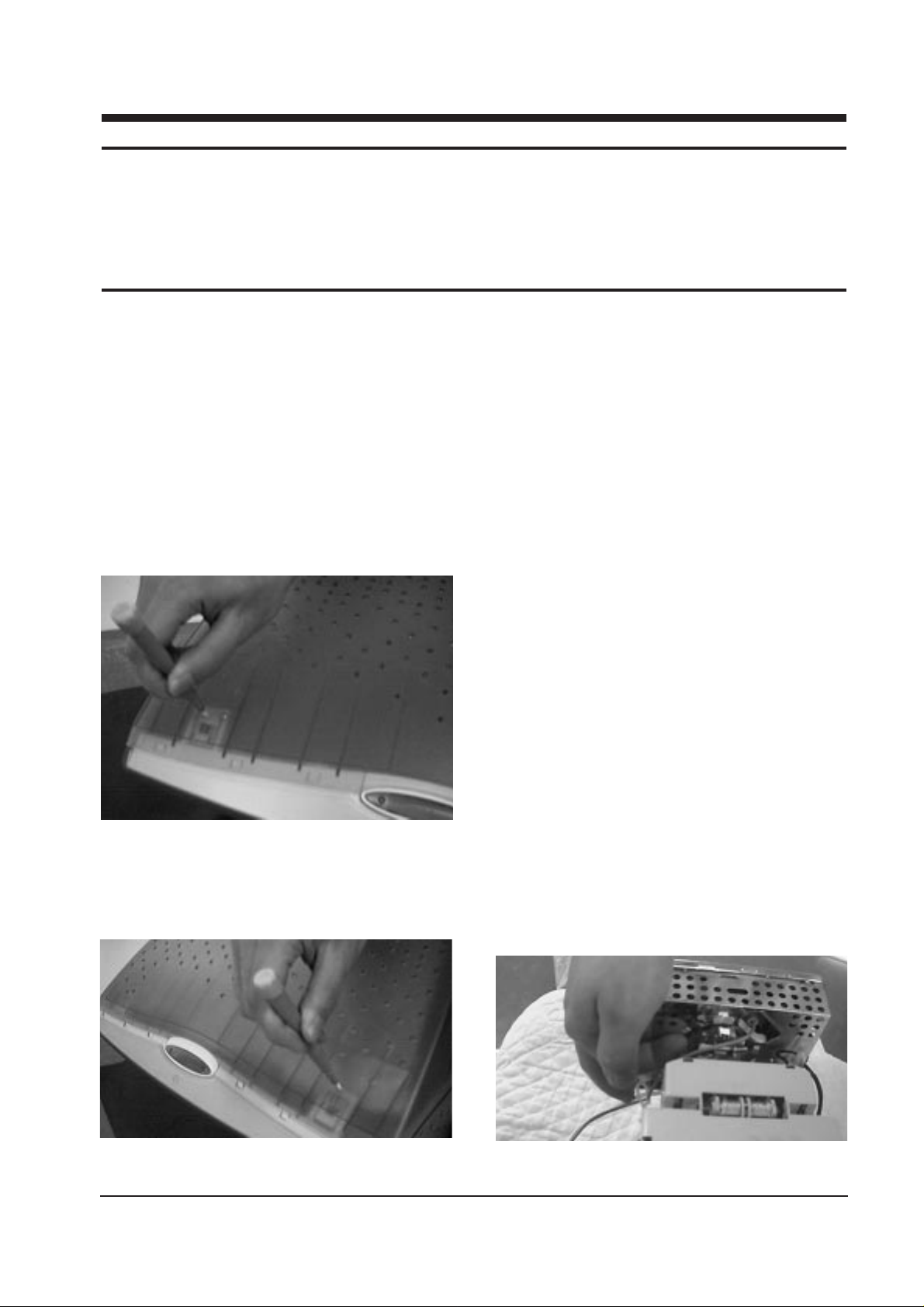
4. Push the Opening jig each groove along the
top of the monitor till it makes a “ttak” sound.
(2 grooves : Left and Right, Make sure each
snap is disengaged.)
5. Squeeze the hold-snap on bottom of the
monitor using your hand.
6. Insert the Opening jig into the groove then
release the hold-snap.
7. When the hold-snap release, lift the Rear
Cover slightly to make sure it doesn’t reengage while you release the snap on the
other side.
8. In a similar manner, Release the hold-snap on
the opposite side.
9. Pull the Rear Cover up off the monitor.
10. Using pinch-nose pliers or ling-nose pliers,
acrefully disconnect the Anode Cap from the
CRT.
Warning: Do not touch the Anode contact
on the CRT (High Voltage may
remain).
Note : If the hold-snap on the bottom of the
Front Cover is broken, secure the
cabinet by applying a 4x16 screw in
the extra holes on each side of the
cabinet.
3-1-2 Removing the CRT Socket PCB
1. Complete all previous steps.
2. Lift up the Video Spring and remove the CRT
Socket PCB from the CRT.
SyncMaster 753DFT 3-1
3 Disassembly and Reassembly
This section of the service manual describes the disassembly and reassembly procedures for the
SyncMaster 753DFT monitor.
WARNING: This monitor contains electrostatically sensitive devices. Use caution when handling
these components.
3-1 Disassembly
Cautions:1. Disconnect the monitor from the power source before disassembly.
2. To remove the Rear Cover, you must use the special opening jig tool.
Figure 1
Figure 2
Figure 3

3. Disconnect all connectors on the CRT Socket
PCB.
4. Using a solder iron, disconnect Ground (G2)
on the back of the Video Shield and remove
the Shield Cap.
5. Remove the screw on the front of the Shield
Socket.
6. Desolder the 4 tabs on the CRT Socket PCB
and remove Shield.
7. Place the Video PCB on a flat, level surface
that is protected from static electricity.
3-1-3 Removing the Main PCB
1. Complete all previous steps.
2. Disconnect the Degaussing Coil at GT601 and
GT602 on the Main PCB.
3. Disconnect all easily accessible ground wires
on the Main PCB and Bottom Chassis.
4. Disconnect the DY connector at the CN303
connector on the Main .
5. Using the jig, release the snaps (2) connecting
the Front Cover and Main PCB then lift up the
Bottom to separate the two Shield.
6. Remove the screws on the back and along
each side of the Bottom Chassis.
7. Carefully lift the Main PCB Ass’y and remove
the remaining ground wires.
8. Place the Main PCB Ass’y on a flat, level
surface that is protected from static electricity.
3-1-4 CRT Ass’y Disassembly
1. Complete all previous steps.
2. Straighten the Degaussing Coil Assembly
coated metal ties and lift the Coil Ass’y from
the CRT.
3. Remove the four corner screws and lift the
CRT up and away from the Front Cover
Assembly and place it on a padded surface.
Caution: Do not lift the CRT by the neck.
If you will be returning this CRT to
the monitor, be sure to place the CRT
face downward on a protective pad.
3 Disassembly and Reassembly
3-2 SyncMaster 753DFT
Figure 4
3-2 Reassembly
Reassembly procedures are in the reverse order of Disassembly procedures.
 Loading...