

samsung TC29J6MNX-XAX Service Manual
DVD Television
Chassis : V18B
Model: TC29J6MNX/XAX
DVD Television Cassette Recorder CONTENTS
Precautions
Specifications
Disassembly and Reassembly
Alignment and Adjustment (Electrical)
Troubleshooting
Exploded View and Parts List
Electric Parts List
Block Diagram
Schematic Diagrams
1.
2.
3.
4.
5.
6.
7.
8.
9.

ELECTRONICS
© Samsung Electronics Co., Ltd. JUN. 2003
Printed in Korea
AA82-00829A
This Service Manual is a property of Samsung Electronics Co.,Ltd.
Any unauthorized use of Manual can be punished under applicable
International and/or domestic law.

4-2 Factory (“Service”) Mode
Alignment and Adjustments (Electrical)
Samsung Electronics 4-1
4. Alignment and Adjustments (Electrical)
4-1 Preadjustment
4-1-1 Factory Mode
1. Do not attempt these adjustments in the Video
Mode.
2. The Factory Mode adjustments are necessary
when either the EEPROM (IC901) or the CRT
is replaced.
3. Do not tamper with the “Adjustment” screen
of the Factory Mode menu. This screen is
intended only for factory use.
4-1-2 When EEPROM (IC901) Is Replaced
1. When IC901 is replaced all adjustment data
revert to initial values. It is necessary to reprogram this data.
2. After IC901 is replaced, warm up the TV for
10 seconds.
4-1-3 When CRT Is Replaced
Make the following adjustments after setting up
purity and convergence:
White Balance
Sub-Brightness
Vertical Center
Vertical Size
Horizontal Size
4-2-1 Procedure for the “Adjustment” Mode
1. This mode uses the standard remote control.
The Service Mode is activated by: (1) pressing
the “FACTORY” service key on the local-keyboard, or (2) by entering the following remotecontrol sequence (within 2 seconds):
STAND-BY →MUTE →1 → 8 →2 →
POWER ON
2. The “SERVICE (FACTORY)” message will be
displayed. The Service Mode has three components: Adjustment, Option Bytes and Reset.
3. Access the Adjustment Mode by pressing the
“SELECT” keys ( ). The adjustment parameters are listed in the accompanying table,
and selected by pressing the “SELECT” keys
(s,t).
4. Selection sequences for the NTSC systems:
down or up key:
CAP>SBT>SCT>SCR>STT>BLR>BLG>RG>
GG>BG>PWL>SC>VSL>VA>NVS>NHS>
EW1>EWP>EWUC>EWLC>VSC>HP>HB>
TC>EW2>CDL>BKS>NDL>WS>VM>AKB>
CB>BPS>SCL>SVM>SCBT
5. The “SELECT” keys (s,t) increase or decrease
the adjustment values, (stored in the
non-volatile memory) when Adjustment Mode
is cancelled.
Alignment and Adjustments (Electrical)
4-2 Samsung Electronics
OSD
CAP
SBT
SCT
SCR
STT
BLR
BLG
RG
GG
BG
PWL
SC
VSL
VA
NVS
AKB
CB
BPS
Initial
10
8
16
3
9
32
32
32
32
32
12
18
32
18
32
0
0
1
Adjust
Fix
Fix
Fix
Fix
Fix
Fix
Fix
Fix
Range
0-23
0-23
0-13
0-13
0-63
0-63
0-63
0-63
0-63
0-15
0-63
0-63
0-63
0-63
0-1
0-1
0-1
Function
CAPTION Position
Sub Brigh
Sub Contrast
Sub Color
Sub Tint
Low Light R
Low Light G
High Light R
High Light G
High Light B
Peak white level
S-Correction
Vertical Slope
Vertical Amplitude
Vertical shift
AKB on/off (FS Check)
Chroma Bandpass
Bypass Delay Lune
Adjust
Fix
Fix
Fix
Fix
Fix
Fix
Fix
Fix
Fix
Fix
Initial
32
40
32
18
18
32
34
32
26
32
12
1
5
3
3
2
2
45
OSD
NHS
EW1
EWP
EWUC
EWLC
VSC
HP
HB
TC
EW2
CDL
BKS
NDL
WS
VM
SCL
SVM
SCBT
Range
0-63
0-63
0-63
0-63
0-63
0-63
0-63
0-63
0-63
0-63
0-15
0-1
0-15
0-3
0-3
0-3
0-3
0-63
Function
Horizon Shift
EW
EW (Panorama)
Upper Corner
Lower Corner
Vertical scroll
H-Paralleogram
Horizontal Bow
EW Trapezium
Panorama EW(Non Vse)
Cathode Drive Level
Black Stretcher
NTSC Delay
White Stretch
Amplitude of Scan Velocity
Soft Clipping Level
SVM Out & RGB Out Delay
Screen Adj Bright Level
4-2-2 Adjust
4-2-3 AGING Mode(Reference Only)
This pattern is used for pre-heating the CRT during manufacturing-it is accessed in the factory by twice
pressing the “FACTORY” key.
Even if the TV power is cut off, the Aging Mode is not cancelled.
The “AGING” marking is displayed on the screen.
The AGING mode is cancelled by epresing the “FACTORY” key.
Alignment and Adjustments (Electrical)
Samsung Electronics 4-3
4-2-4 Option
The Reset Mode is used during factorying inspection
Function Reset : After Factorying Reset, the following items itens revert to their initial values.
1. Volume 10
2. Channel ANT 3
3. P- STD MEMORY
4. Auto Power ON
5. NR OFF
Cautim : When the EEPROM is replaced ; all items revert to their initial values.
4-2-5 Reset
The VCR Test Mode is used during factorying inspection or when exchange VCR deck.
* Entering : STBY Mode -> factory key -> Power key (light up all LED)
Function : “9” -> Head Switch Auto Adjustment.
“5” -> Env Center point Auto Adjustment.
“TRK + “ -> Env max point Adjustment.
“TRK - “ -> Env min point Adjustment.
* Cancellation : pull out power cord.
4-2-6 VCR Test Mode (Reference Only)
NO
1
2
3
4
5
6
7
8
9
10
11
OSD
VIDEO MUTE
ZOOM
AUTO POWER
AUDIO MUTE
LANGUAGE
2H comb
BLUE SCREEN
V-CHIP
ANTENNA
S-VIDEO
VCR HEAD
Adjust
2 (X100mS)
NOR/ZOOM/16:9
ON
ON
English
ON
ON
ON
IRC
OFF
HIFI
Range
off/x1/x2/x3...
NORMAL,NOR/ZOOM,NOR/ZOOM/16:9
ON/OFF
ON/OFF
English/Espanol/Franch
(21"/29" option)
ON/OFF
ON/OFF
IRC/AFN
ON/OFF
HIFI/4HD/2HD

Alignment and Adjustments (Electrical)
4-4 Samsung Electronics
4-3 Other Adjustments
4-3-1 General
1. Usually, a color TV needs only slight
touch-up adjustment upon installation.
Check the basic characteristics such as height,
horizontal and vertical sync and focus.
2. The picture should have good black and white
details. There should be no objectionable
color shading; if color shading is present,
perform the purity and convergence adjustments described below.
3. Use the specified test equipment or its
equivalent.
4. Correct impedance matching is essential.
5. Avoid overload. Excessive signal from a sweep
generator might overload the front-end of the
TV. When inserting signal markers, do not
allow the marker generator to distort test
results.
6. Connect the TV only to an AC power source
with voltage and frequency as specified on the
backcover nameplate.
7. Do not attempt to connect or disconnect any
wires while the TV is turned on. Make sure
that the power cord is disconnected before
replacing any parts.
8. To protect against shock hazard, use an
isolation transformer.
4-3-2 Automatic Degaussing
A degaussing coil is mounted around the
picture tube, so that external degaussing after
moving the TV should be unnecessary. But
the receiver must be properly degaussed upon
installation.
The degaussing coil operates for about 1
second after the power is switched ON. If the
set has been moved or turned in a different
direction, disconnect its AC power for at least
10 minutes.
If the chassis or parts of the cabinet become
magnetized, poor color purity will result. If
this happens, use an external degaussing coil.
Slowly move the degaussing coil around the
faceplate of the picture tube and the sides and
front of the receiver. Slowly withdraw the coil
to a distance of about 6 feet before removing
power.
4-3-3 High Voltage Check
CAUTION: There is no high voltage
adjustment on this chassis. The B+ power
supply must be set to +130 volts (Full color
bar input and normal picture level).
1. Connect a digital voltmeter to the second
anode of the picture tube.
2. Turn on the TV. Set the Brightness and
Contrast controls to minimum (zero beam
current).
3. The high voltage should not exceed 30KV.
4. Adjust the Brightness and contrast controls to
both extremes. Ensure that the high voltage
does not exceed 30KV under any conditions.

Alignment and Adjustments (Electrical)
Samsung Electronics 4-5
4-3-4 FOCUS Adjustment
1. Input a CROSS hatch signal.
2. Adjust the tuning Focus VR for the clearest picture.
3. Adjust the FOCUS control for well defined scanning lines in the center area of the screen.
4-3-5 Screen Adjustment
1. Turn to the White Signal.
2. Adjust the VR screen for a normal picture is (no blooming or flyback line).
Input the Factory -> G2-Adjust choice -> Screen VR tuning OK Mode
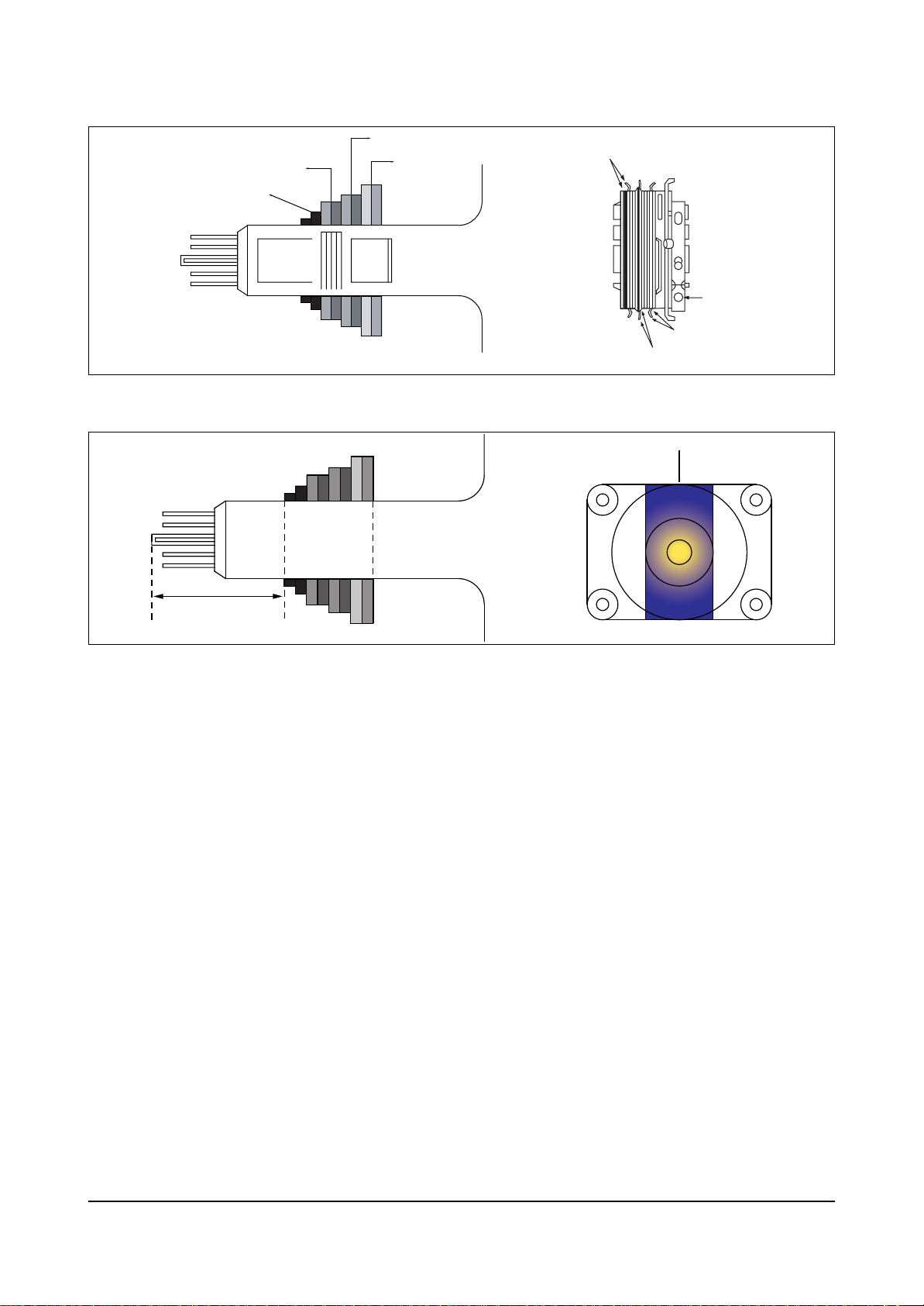
4-3-6 Purity Adjustment
1. Warm up the receiver for at least 20 minutes.
2. Plug in the CRT deflection yoke and tighten the clamp screw.
3. Plug the convergence yoke into the CRT and set in as shown in Fig. 5-1.
4. Input a black and white signal.
5. Fully demagnetize the receive by applying an external degaussing coil.
6. Turn the CONTRAST and BRIGHTNESS controls to maximum.
7. Loosen the clamp screw holding the yoke. Slide the yoke backward or forward to provide
vertical green belt. (Fig. 5-2).
8. Tighten the convergence yoke.
9. Slowly move the deflection yoke forward, and adjust for the best overall green screen.
10. Temporarily tighten the deflection yoke.
11. Produce blue and red rasters by adjusting the low-light controls. Check for good purity
in each field.
12. Tighten the deflection yoke.
Alignment and Adjustments (Electrical)
4-6 Samsung Electronics
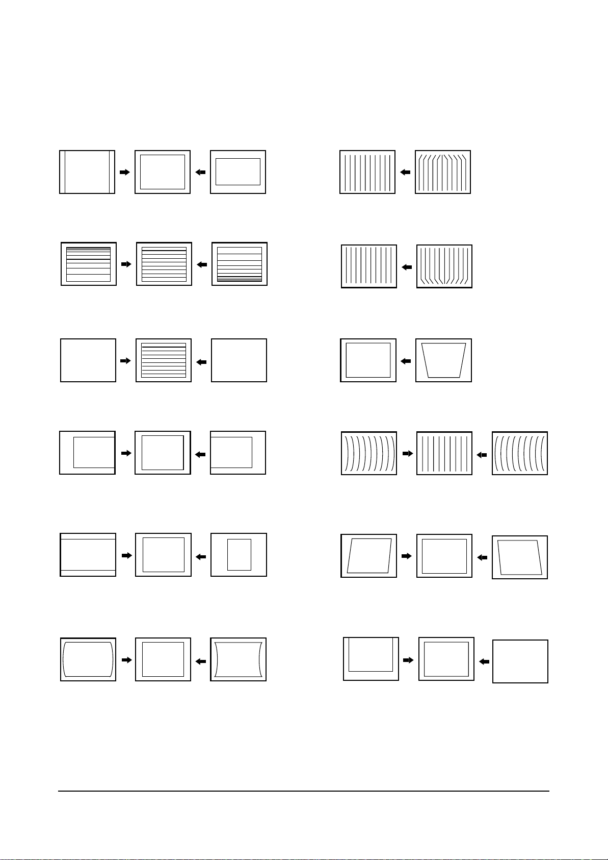
4-3-7 I C BUS GEOMETRIC Adjust
2
1. V SIZE(VA)
3. V LINEARITY (VSL)
5. V S CORRECTION (SC)
2. UP CPIN (EWUC) : 29" Only
4. LO CPIN (EWLC) : 29" Only
6. TILT (TC)
7. H POSITION (NHS)
9. H SIZE(EWI)
11. PIN COMP (EWP)
8. AFC BOW (HB)
10. AFC ANGLE (HP)
12. V POSITION (NVS)
Alignment and Adjustments (Electrical)
Samsung Electronics 4-7
4-3-8 White Balance Adjustment
4-4-7 (A) HIGH-LIGHT ADJUSTMENT
1. Input either a Lion Head or a “pure white” pattern.
2. Warm up the TV for 30 minutes.
3. Check the data in the Service Mode
4. Adjust RG, BG in the Factory Mode.
4-4-7 (B) LOW-LIGHT ADJUSTMENT
1. Automatically accomplished during the high-light adjustment.
6 Pole Magnet
Fig. 5 -1 Convergence Magnet Assembly
Fig. 5-2 Center Convergence Adjustment
Clamper
Screw
4 Pole Magnet
2 Pole Magnet
2 POLE
PURITY
YOKE
CLAMP
SCREW
6 POLE
CONVERGENCE
4 POLE
CONVERGENCE
Vertical Green Belt
31m/m
Alignment and Adjustments (Electrical)
4-8 Samsung Electronics
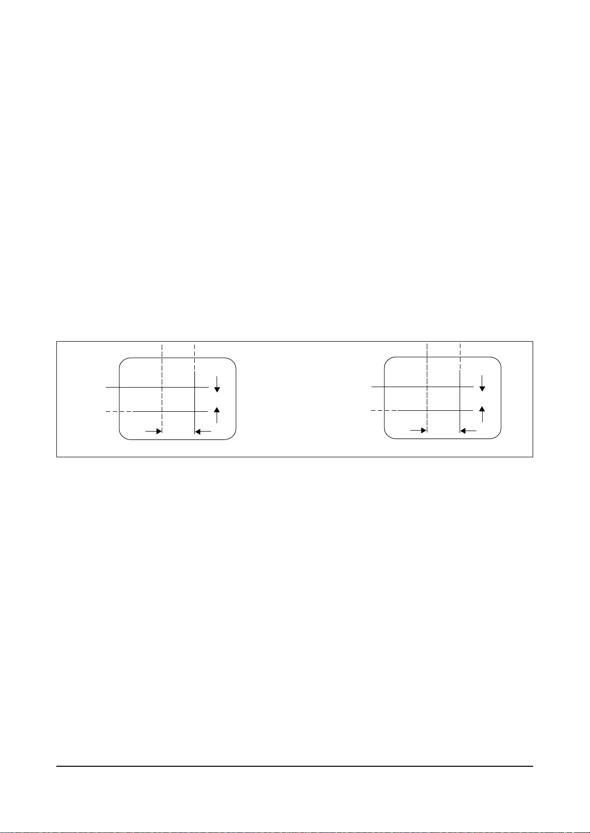
4-3-8 Center Convergence Adjustment
1. Warm up the receiver for at least 20 minutes.
2. Adjust the two tabs of the 4 pole magnets to
change the angle between them. Superimpose
the red and blue vertical lines in the center
area of the screen.
3. Adjust the Brightness and Contrast controls for
a well defined picture.
4. Adjust the two-tab pairs of the 4 pole magnets,
and change the angle between them.
Superimpose the red and the blue vertical
lines in the center area of the screen.
5. Turn the both tabs at the same time, keeping
the angle constant, and superimpose the red
and blue horizontal line in the center of the
screen.
6. Adjust the two-tab pairs of the 6-pole magnets
to superimpose the red and blue line onto the
green. (Changing the angle affects the vertical
lines, and rotating both magnets affects the
horizontal lines.)
7. Repeat adjustments 2~6, if necessary.
8. Since the 4-pole magnets and 6-pole magnets
interact, the dot movement is complex
(Fig. 5-3).
Fig 5-3 Center Convergence Adjustment
BLUE
BLUE
RED
RED/BLUE
RED/BLUE
GREEN
RED
4-Pole Magnet Movement
GREEN
6-Pole Magnet Movement
Troubleshooting
Samsung Electronics 5-1
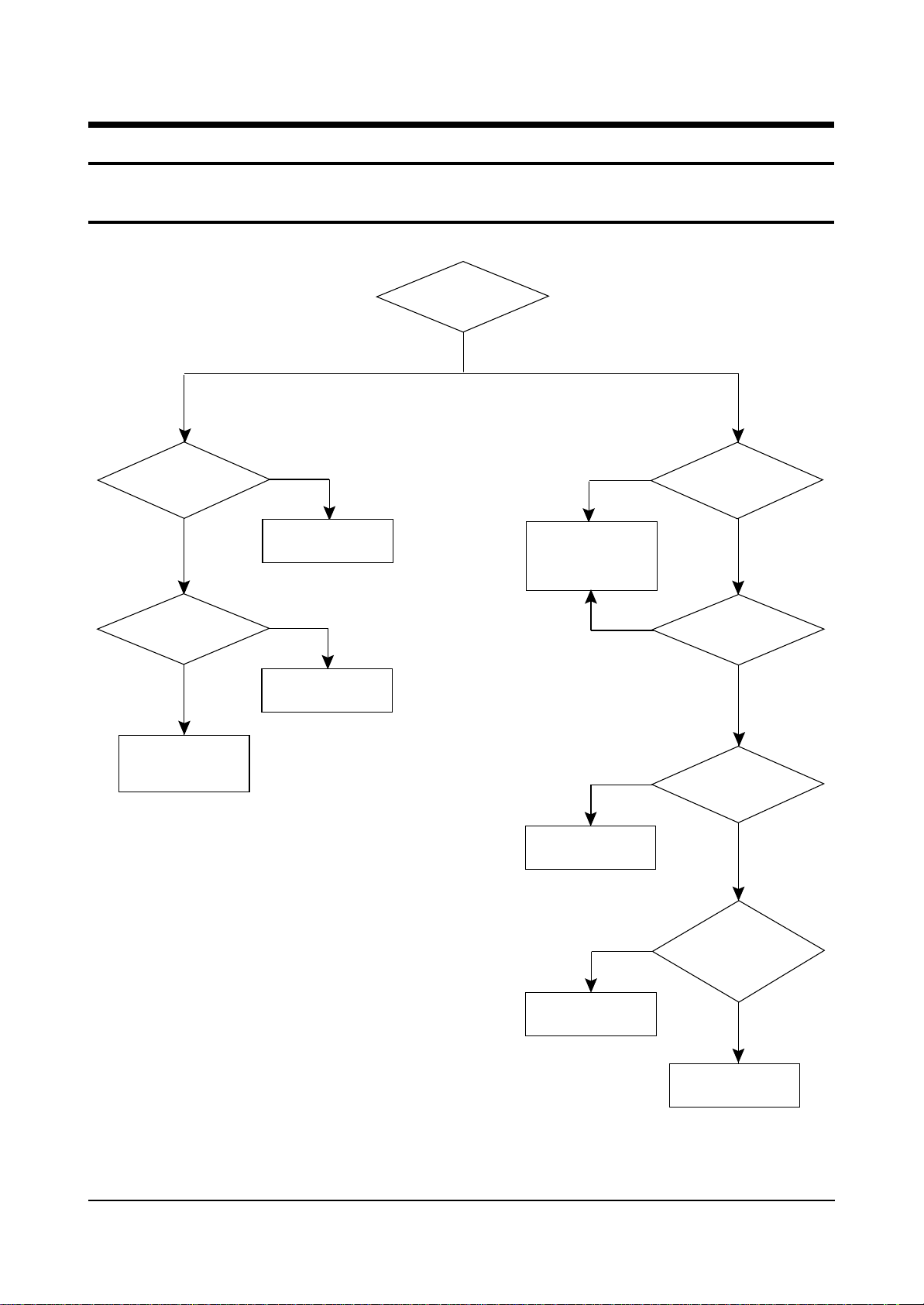
5. Troubleshooting
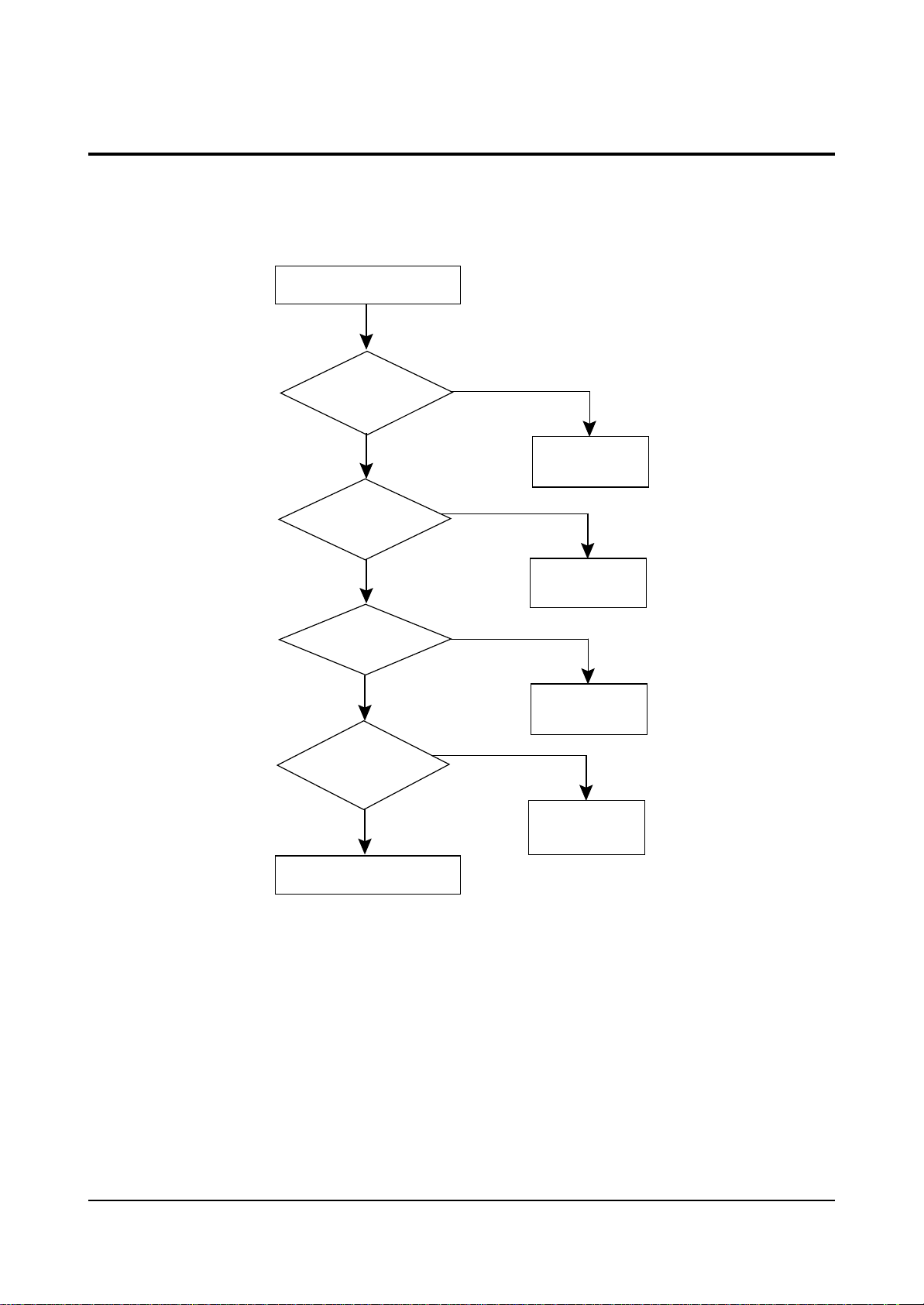
5-1 No Power (No Picture on)
Yes
Check
both terminal voltages
of C815
Check both
terminal voltages of
C806 (280~300V).
Check D801S
FP801S
No
Is IC801S Pin 3
19~22V?
Check IC801S
Check/Replace
DZ801,DZ804,
DZ802,PC801S
No
Yes
No
Yes
Check
Voltage of 8V, 12V, 6V,
20V power line..
Check whether
each power line
is short or open.
No
No
Yes
Is Q805-E
Output Voltage 5V?
Is Q901-E
Voltage 3.3V?
Check/Replace
Q901, DZ901, D901
Check
Q811-B is High
when power is On
(about 0.6~2.0v)
Check/Replace
IC902
Check /Replace
Q810, Q812, DZ805
Yes
Yes
No
No
Yes

Troubleshooting
5-2 Samsung Electronics
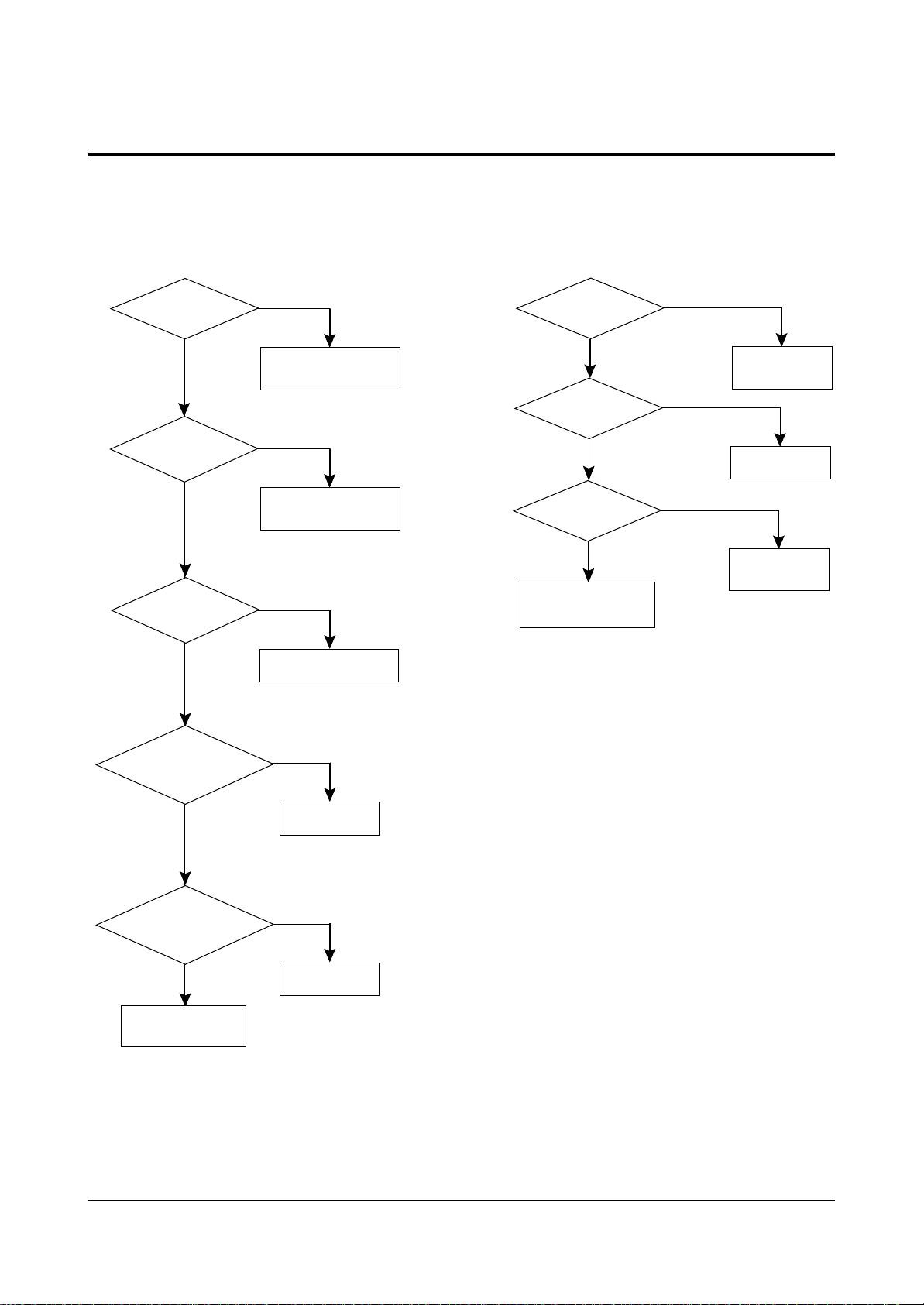
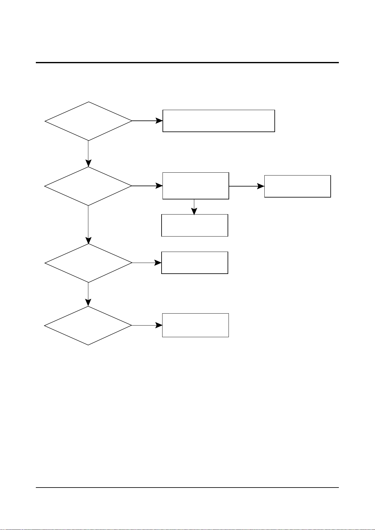
5-2 No Power (No Picture)
5-3 E/W Correction Not
Q810-E Output
Voltage 8V?
Yes
H-Drive Out?
(CN401 #6)
Yes
FBT Output line
Voltage?
No
Check/Replace
Q810, DZ809
No
Check (IC902)
No
Check/Replace
Q401, Q402, D414
E/W Out check?
(CN401 #5)
Yes
Check Q403
Drain Pin E/W wave
output?
Q403,
R413,L405
Check/Replace
No
Check/Replace
IC902
No
Troubleshooting
Samsung Electronics 5-3
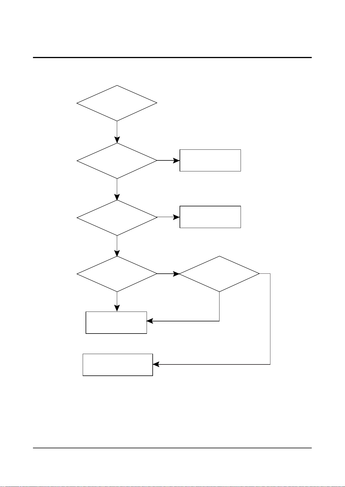
5-4 No Raster / No RF Signal
* No Raster
Q810-E Output
Voltage?
Yes
Check H-Drive
(CN003 #8)
Yes
Check Q402,
Q401, D414
Yes
No
Check Q811-B(0.6~2.0V)
Check IC902 #1
No
Check/Replace
IC902
No
Check/Replace
* No signal
IC902 #1 TV
Power High?
Yes
Q810-E Output
Voltage 8V?
Yes
Tuner B+
5V?
Yes
Tuner 33V
Line Check
No
Check/Replace
IC902
No
Replace Q810
No
Tuner 5V
Line Check
Check
R405, R435
R424, R425
Check the
CRT PCB, IC501,
R513, L501
No
Replace
No
Check/Replace
No
Check/Replace
Troubleshooting
5-4 Samsung Electronics
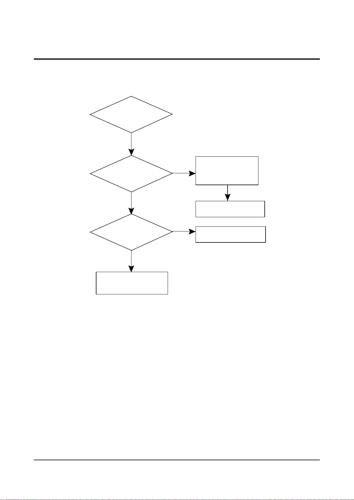
5-5 No Sound
Power On
Yes
Check Amp
IC601 B+(12V:#3,#13)
In Power Board
Yes
Check Amp
Mute Pin(High:#6,#7)
In Power Board
Yes
Check Tone
Control IC601 #21,#22
In Main Board
Yes
Check ICM501
L,R out check and SIF
Input check
Yes
No
Check/Replace
FA803S,D808
A+13.5V Line
No
Check/Replace
Q601&A-Mute
No
Check/I2 Line
IC902 #71, #72
No
Check/Replace
ICM501&HIFI/
TM Block
Check/Replace Speaker

Troubleshooting
Samsung Electronics 5-5
5-6 Horizotal Line
5-7 No Picture (Sound OK)
1 Check the Brightness, Contrast and Color adjustments
2. Check: AV Picture
3. See Signal Block Diagram
5-8 No Sound (Picture OK)
1. Check the Volume adjustment level.
2. Check AV Video
3. See Signal Block Diagram
IC301(LA7845)
1# 13.5V, 6# 18V
Output?
Yes
Check IC301
Check/Replace Speaker
#2 Vertical wave
output?
Yes
D301,DZ302
DZ303,DZ304,DZ305
DZ306 check?
Yes
Replace IC301(LA7845)
No
Check/Replace
R425,R424,
D401,D402
No
IC301 #2 vertial
wave input check
No
Replace

Troubleshooting
5-6 Samsung Electronics
5-9 RF Weak Signal (Playback, AV Mode OK)
1. Check Tuner (TU01S) B+. Check: 8V
33V (DZ201). Check 5V
5-10 No Vertical SCAN
1. Check R425, D401
2. Check IC301, #2
3. Check Chroma module Vertical-out Line
4. Check DY Connector
5-11 Horizontal Size
1. Check C411, R421, Q403, R405
5-12 On-Screen Display Missing
1. Check IC902 #56, #57, #58

Troubleshooting
Samsung Electronics 5-7
Normal
Abnormal
Abnormal
Normal
Normal
Check
the audio signal of ICM301
Pin 10
Check the line of ICM501 Pin 62
(Mono Audio Out Line)
Check if ICM301
Pin 53, 54, 55 is Low
(Serial Data)
Replace ICM301
Check the B 5V
of ICM301 Pin 77
Check AC head
line and CNM302
Check the B 5V line
Check Serial Line &
ICM601
Replace ICM301
Check the Audio
signal of ICM301
Pin 2, 3
Abnormal
Abnormal
Normal
Abnormal
5-13 No Audio During Playback (Mono Audio)
Troubleshooting
5-8 Samsung Electronics
Normal
Abnormal
Abnormal
Normal
Normal
Check
the audio signal of ICM501
Pin 53,57
Check the IC601(TONE Control)
Pin 24:+8V, Pin 21,22:I
2
C
Check the ICM501
Pin 42,43
(I
2
C Data)
Replace ICM501
Check the B5V/B9V
of ICM501 Pin25,40,58
Check Rotaly Head
line and CNM301
Check the B5V/B9V line
Check the I2C Line
ICM601 Pin 66,67
Replace Head Drum
Check the HIFI
Env ICM501
Pin 30
Abnormal
Abnormal
Normal
Abnormal
5-14 No Audio During Playback (HIFI)
Troubleshooting
Samsung Electronics 5-9
5-15 No Audio During Record (Mono Audio)
Press
the "REC" button
for the recording
mode
Normal
Check the audio
signal of ICM301
Pin 9
Normal
Check the bias signal
ICM301 Pin 6
Normal
Check CNM302
Pin 4, 5, 6
Normal
Check AC head
Abnormal
Abnormal
Abnormal
Normal
Check the audio signal
of ICM301 Pin 76
Replace ICM301
Check the REC bias
signal of FLM301
Check/Replace
Abnormal
FLM301, QM304, QM302
Troubleshooting
5-10 Samsung Electronics
5-16 No Audio During Record (HIFI Audio)
Press
the "REC" button
for the recording
mode
Normal
Check the FM
signal of ICM501
Pin 21
Normal
2
Check the I
C Line
ICM501 Pin 42,43
Normal
Check/Replace
CNM301&Head Drum
Check the REC-Mute
of ICM501 Pin 29
(DM501(+)) High
Abnormal
Check the ICM601 Pin 68
Abnormal
Check the ICM601

Troubleshooting
Samsung Electronics 5-11
5-17 No Playback
Insert a video tape and
start PLAYBACK
Check the tape loading
Normal
Check
ICM601 Pin 76, 77
(Start/end sensor)
OK
Check
the Rotation of Cylinder
Normal
Check
ICM601 Pin 24
(SW 30Hz)
Normal
Abnormal
NO
Abnormal
Abnormal
Check :
ICM601 Pin 38 : High
ICM601 Pin 39 : Low
Abnormal
Replace ICM601
Check the tape
Refer to "Cylinder
doesn't rotate"
Check ICM601
Pin 97(D-FG)
and Pin 96 (D-PG)
Check the rotation
of capstan
Normal
Check ICM601
Pin 98,99
Normal
Check
ICM601 Pin 34,35,36
( PROG, SW)
Normal
Replace ICM601
Abnormal
Abnormal
Stop Mode
Refer to "Capstan
doesn't Rotate"
Check PTM602, PTM601,
T-Reel takeup sensor
Check the
loading motor
 Loading...