

Samsung TB-331VDZ1S, TB-501VDZ1S, TW531VCZ1S, TB-531VCT1X, TW331VDZ1S Alignment and Adjustments
...
Samsung Electronics 4-1
4-1 Deck Parts Locations
4-1-1 Deck (Top View)
1
2
3
4
5 6
7
8
9
10
11
12
13
141516
17
18
19
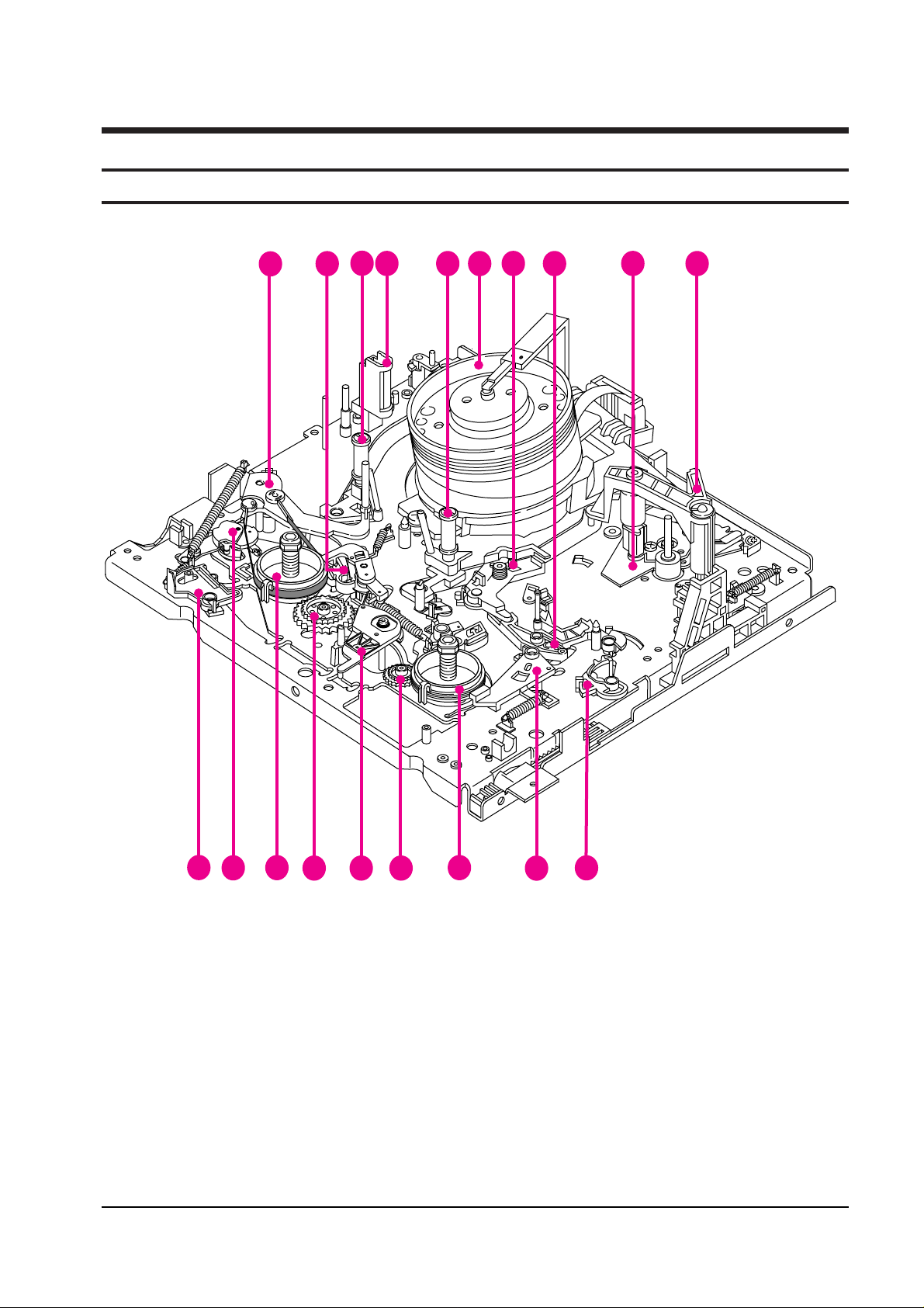
Fig.4-1 Deck Top Parts Location (DX7-A/DX8-A DECK ONLY)
4. Alignments and Adjustments (Mechanical)
1. ARM TENSION FULL ASS’Y
2. BRAKE MAIN “L” ASS’Y
3. GUIDE ROLLER ASS’Y “T”
4. FULL ERASE HEAD
5. GUIDE ROLLER ASS’Y “S”
6. CYLINDER ASS’Y
7. LEVER PINCH COMP ASS’Y
8. LEVER PINCH CAM
9. FULL ACE HEAD AAS’Y
10. UNIT PINCH ROLLER ASS’Y
11. LEVER REVIEW
12. BRAKE SUB “R” ASS’Y
13. REEL DISK “R” ASS’Y
14. GEAR RELAY “T” ASS’Y
15. IDLER ASS’Y
16. GEAR RELAY “S” ASS’Y
17. REEL DISK “L” ASS’Y
18. LEVER JOG ASS’Y
(DX8-A/AC ONLY)
19. LEVER REC SWITCH
4-1-2 Deck (Top View)
Alignments and Adjustments (Mechanical)
4-2
Samsung Electronics
1
2
3
465
7
8
9
10
11
12
13
14
151617
18
19
20
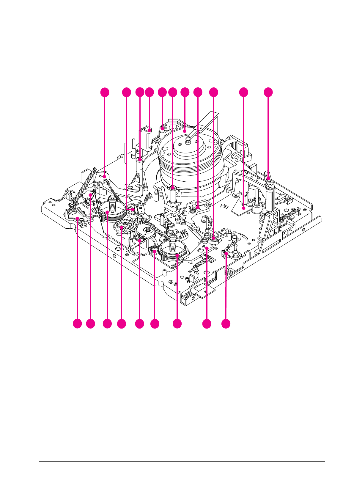
Fig.4-2 Deck Top Parts Location (DX7-AC/DX8-AC DECK ONLY)
1. ARM TENSION FULL ASS’Y
2. BRAKE MAIN “L” ASS’Y
3. GUIDE ROLLER ASS’Y “T”
4. FULL ERASE HEAD
5. HEAD CLEANER ASS’Y
(DX7-AC/DX8-AC ONLY)
6. GUIDE ROLLER ASS’Y “S”
7. CYLINDER ASS’Y
8. LEVER PINCH COMP ASS’Y
9. LEVER PINCH CAM
10. FULL ACE HEAD AAS’Y
11. UNIT PINCH ROLLER ASS’Y
12. LEVER REVIEW
13. BRAKE SUB “R” ASS’Y
14. REEL DISK “R” ASS’Y
15. GEAR RELAY “T” ASS’Y
16. IDLER ASS’Y
17. GEAR RELAY “S” ASS’Y
18. REEL DISK “L” ASS’Y
19. LEVER JOG ASS’Y
(DX8-A/AC ONLY)
20. LEVER REC SWITCH
Alignments and Adjustments (Mechanical)
Samsung Electronics 4-3
4-1-3 Deck (Bottom View)
1
2
3
4
6
5
7
8
9
10
11
13
12
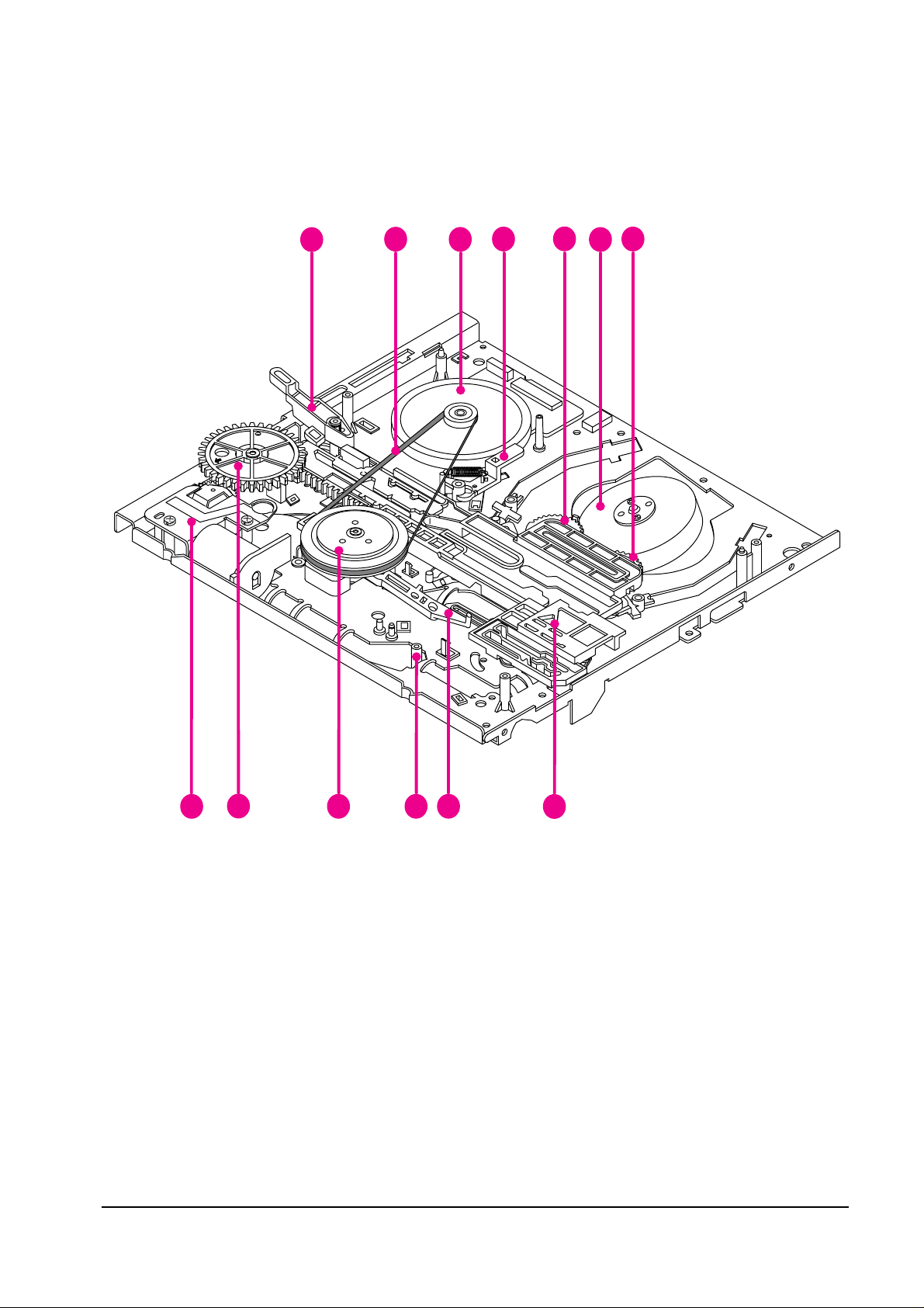
Fig.4-3 Deck Bottom Parts Location
1. LEVER SLIDE PINCH
2. BELT CAPSTAN
3. MOTOR D.D CAPSTAN
4. BRAKE CAPSTAN ASS’Y
5. GEAR LOADING “R” ASS’Y
6. MOTOR CYLINDER
7. GEAR LOADING “L” ASS’Y
8. SLIDE MAIN
9. LEVER REC SWITCH
10. LEVER IDLER CHANGE
11. CLUTCH ASS’Y
12. UNIT LOADING
13. GEAR MASTER
Alignments and Adjustments (Mechanical)
4-4
Samsung Electronics
4-1-4 Housing View
1
2 3
4
6
5
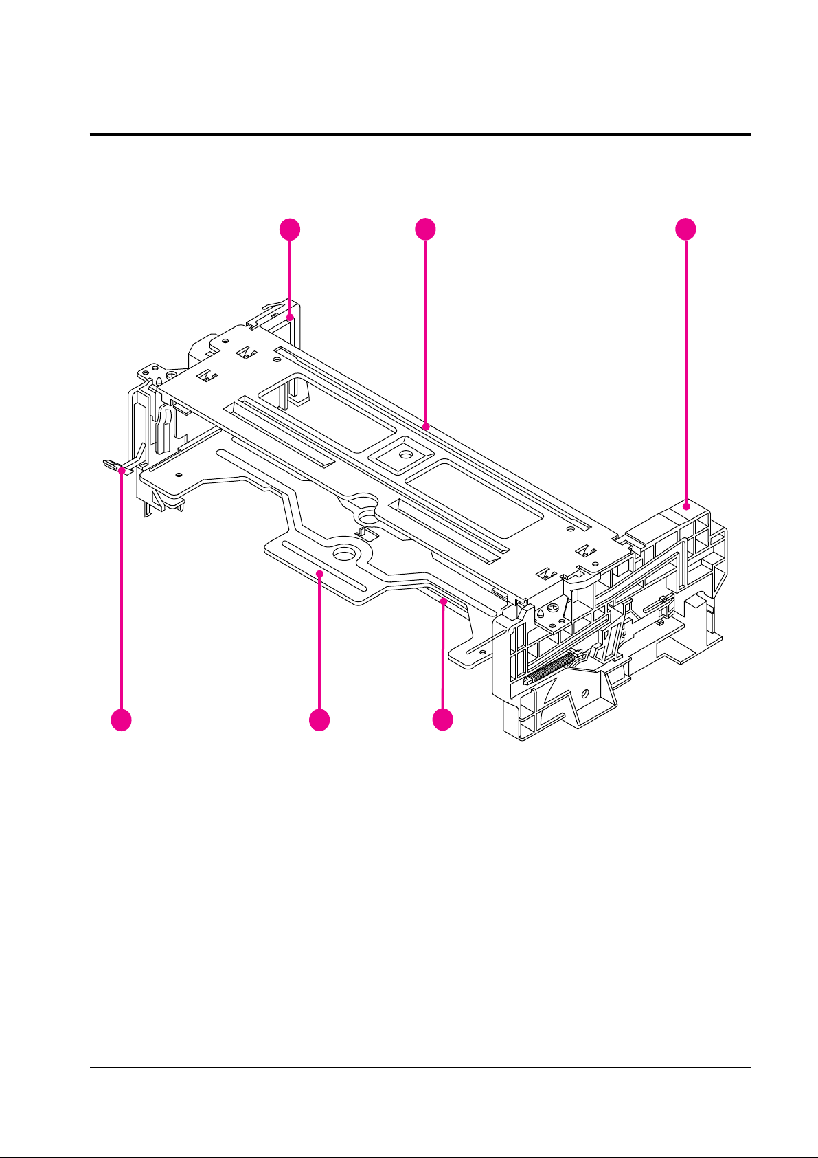
Fig. 4-4 Housing Parts Location
1. CHASSIS SIDE “L” ASS’Y
2. UPPER CHASSIS
3. CHASSIS SIDE “R” ASS’Y
4. SHAFT ARM ASS’Y
5. HOLDER CASSETTE ASS’Y
6. LEVER DOOR
Alignments and Adjustments (Mechanical)
Samsung Electronics 4-5
4-2 Housing Assembly
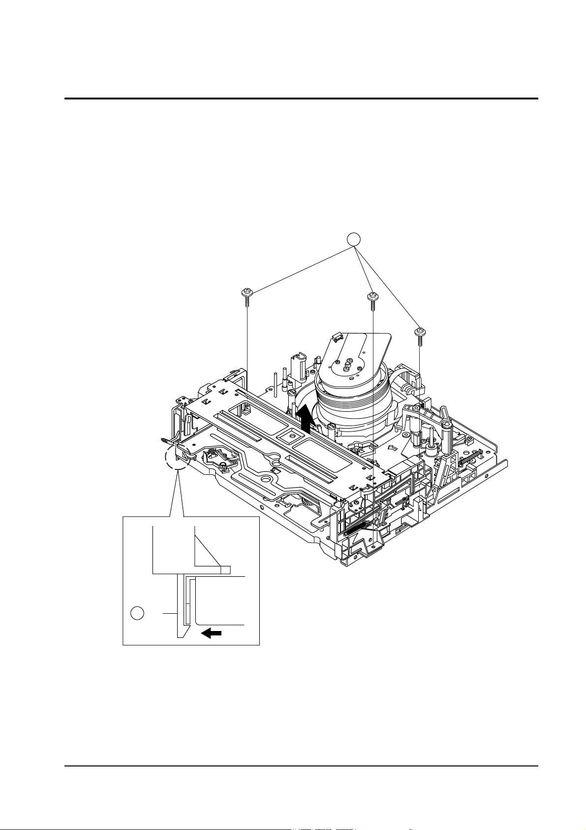
4-2-1 Removal from Main Base
1. Remove 3 Screws ① .
2. Lift the Housing AssÕy in the direction of arrow ÒBÓ, while pushing the tab ➁ in the direction of arrow
ÒAÓ. (Refer to detail drawing)
3 SCREWS
1
MAIN BASE
TAB
"A"
2
Fig. 4-5 Housing Ass’y Removal from Main Base
Alignments and Adjustments (Mechanical)
4-6
Samsung Electronics
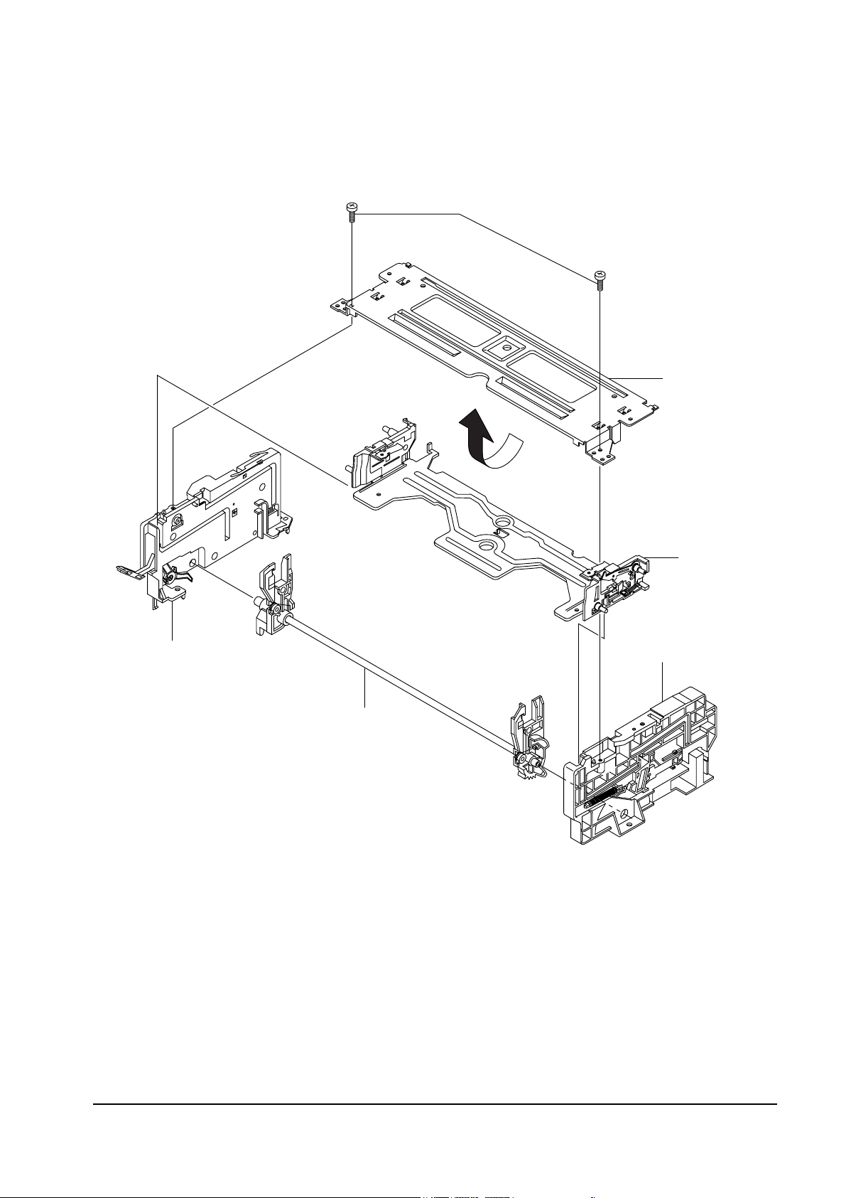
4-2-2 Diassembly
2 SCREWS
UPPER CHASSIS
CHASSIS SIDE "R"
HOLDER
CASSETTE ASS'Y
SHAFT ARM ASS'Y
CHASSIS SIDE "L"
Fig. 4-6 Housing Ass’y Removal
Alignments and Adjustments (Mechanical)
Samsung Electronics 4-7
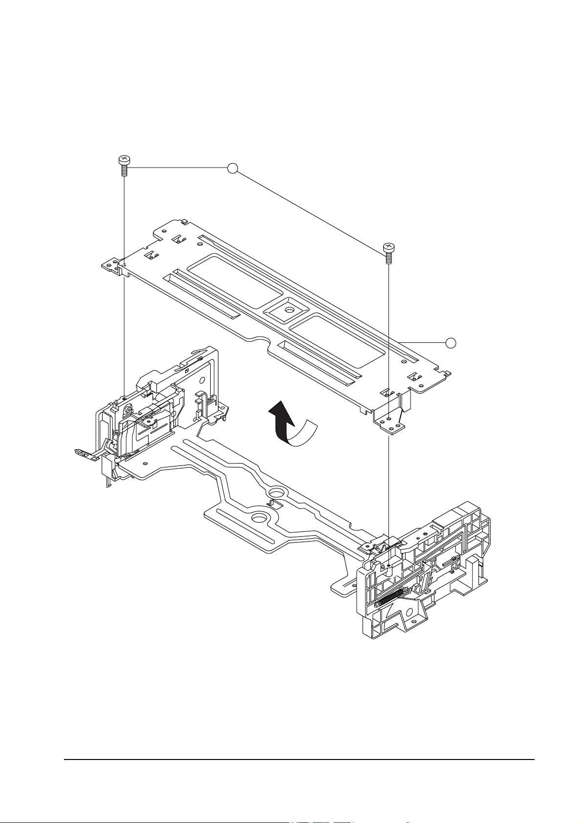
4-2-3 Upper Chassis Removal
1. Remove 2 Screws ①.
2. Lift the Upper Chassis ➁ in the direction of arrow ÒAÓ.
2 SCREWS
UPPER CHASSIS
2
"A"
1
Fig. 4-7 Upper Chassis Removal
Alignments and Adjustments (Mechanical)
4-8
Samsung Electronics
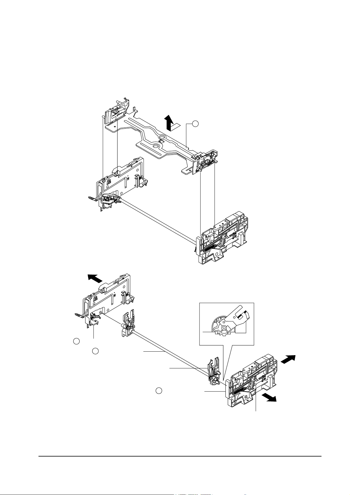
4-2-4 Holder Cassette Ass’y and Chassis Side L/R Removal
1. Lift the Cassette Holder ① in the direction of arrow ÒAÓ (Refer to Fig. A).
2. Remove the Side Chassis ÒLÓ ② and ÒRÓ ➂ from Arm Shaft AssÕy ➃ in the direction of arrow ÒBÓ, ÒCÓ
(Refer to Fig. B).
HOLDER CASSETTE ASS'Y
"A"
1
2
4
SHAFT ARM ASS'Y
CHASSIS SIDE "L"
3
CHASSIS SIDE "R"
SLIDE DAMPER
"B"
<Fig. A>
<Fig. B>
<DETAIL>
(REASSEMBLY OF CHASSIS
SIDE "R" & SHAFT ARM "R")
(SIDE VIEW)
"C"
"D"
SHAFT ARM "R"
Fig. 4-8 Holder Cassette Ass’y and Chassis Side L/R
Alignments and Adjustments (Mechanical)
Samsung Electronics 4-9
4-2-5 Chassis Side “R” Parts Locations
CHASSIS SIDE "R"
(SIDE VIEW "A")
SLIDE DAMPER
LEVER-LID OPENDER
"A"
SPRING-SLIDE DAMPER
SPRING-LID OPENDER
Fig. 4-9 Chassis Side “R” Parts Locations
Note : If you operate the deck when the Cassette AssÕy Holder is removed, the Arm Shaft ÒRÓ and the
Damper Slide are not returned to their original positions. If this happens by accident, push the Damper
Slide of Side Chassis ÒRÓ in the direction of arrow ÒDÓ, and return the Damper Slide in the reverse
direction of arrow ÒDÓ when the Arm Shaft AssÕy is in eject mode.
Alignments and Adjustments (Mechanical)
4-10
Samsung Electronics
4-2-6 Slide Damper Removal
1. Remove the Slide Damper Spring ①.
2. Push the Stopper ➂ of the Side Chassis ÒRÓ ➃. Move the Damper Slide ➁ in the direction of arrow.
3. Align the Damper Slide ✠ with the chassis side tab (as shown detail drawing).
CHASSIS SIDE "R"
CHASSIS SIDE "R" TAB
SLIDE DAMPER
4
STOPPER
3
SLIDE DAMPER
2
SPRING- SLIDE DAMPER
1
Fig. 4-10 Slide Damper Removal
Alignments and Adjustments (Mechanical)
Samsung Electronics 4-11
4-3 Cylinder Ass’y
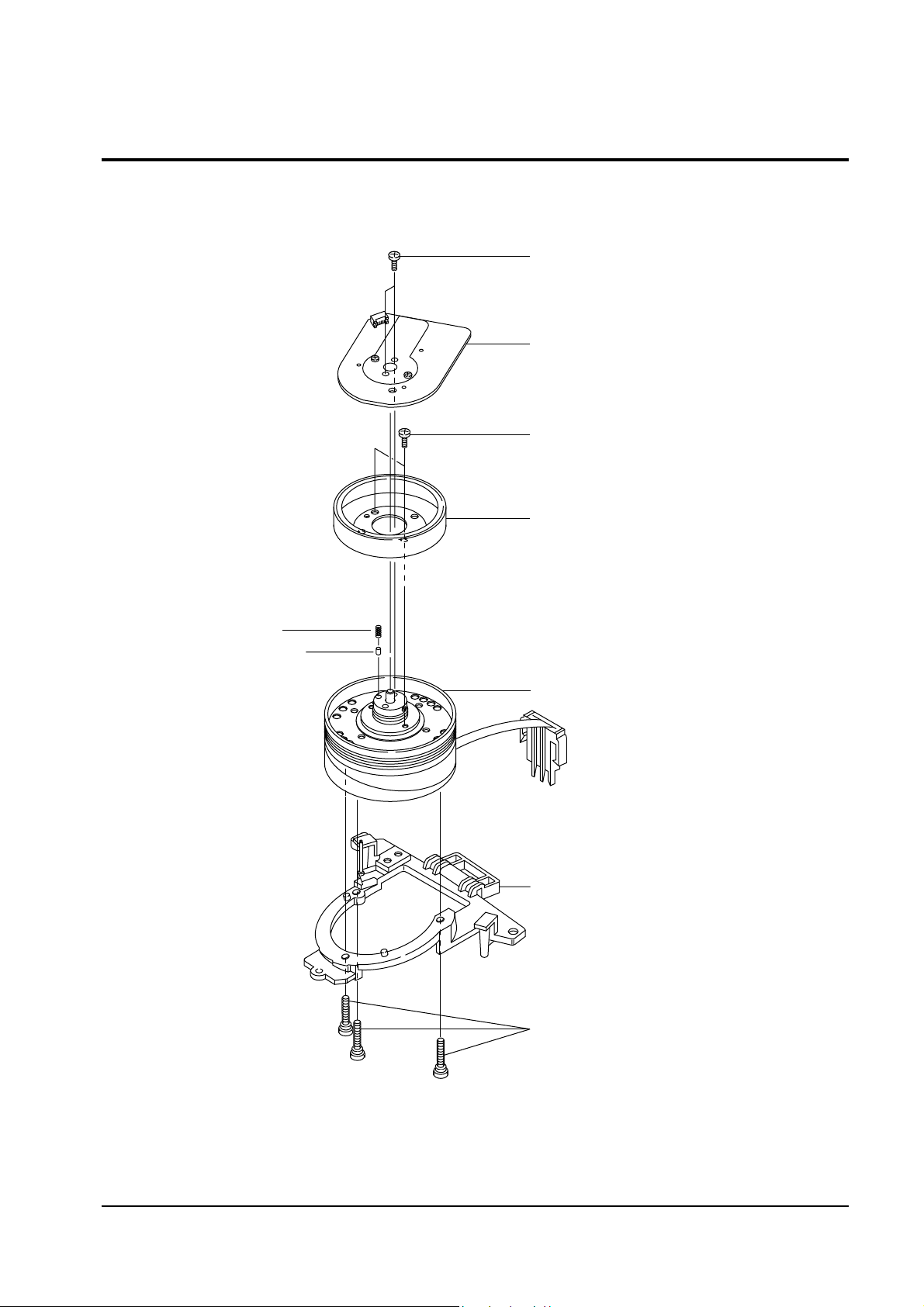
4-3-1 Exploded View of Cylinder Ass’y
ASS'Y MOTOR - ROTOR
ASS'Y - SUB CYLINDER
2 SCREWS
3 SCREWS
2 SCREWS
ASS'Y - MOTOR STATOR
ASS'Y - BASE CYLINDER
SPRING
CARBON TIP
Fig. 4-11 Exploded View of Cylinder Ass’y
Alignments and Adjustments (Mechanical)
4-12
Samsung Electronics
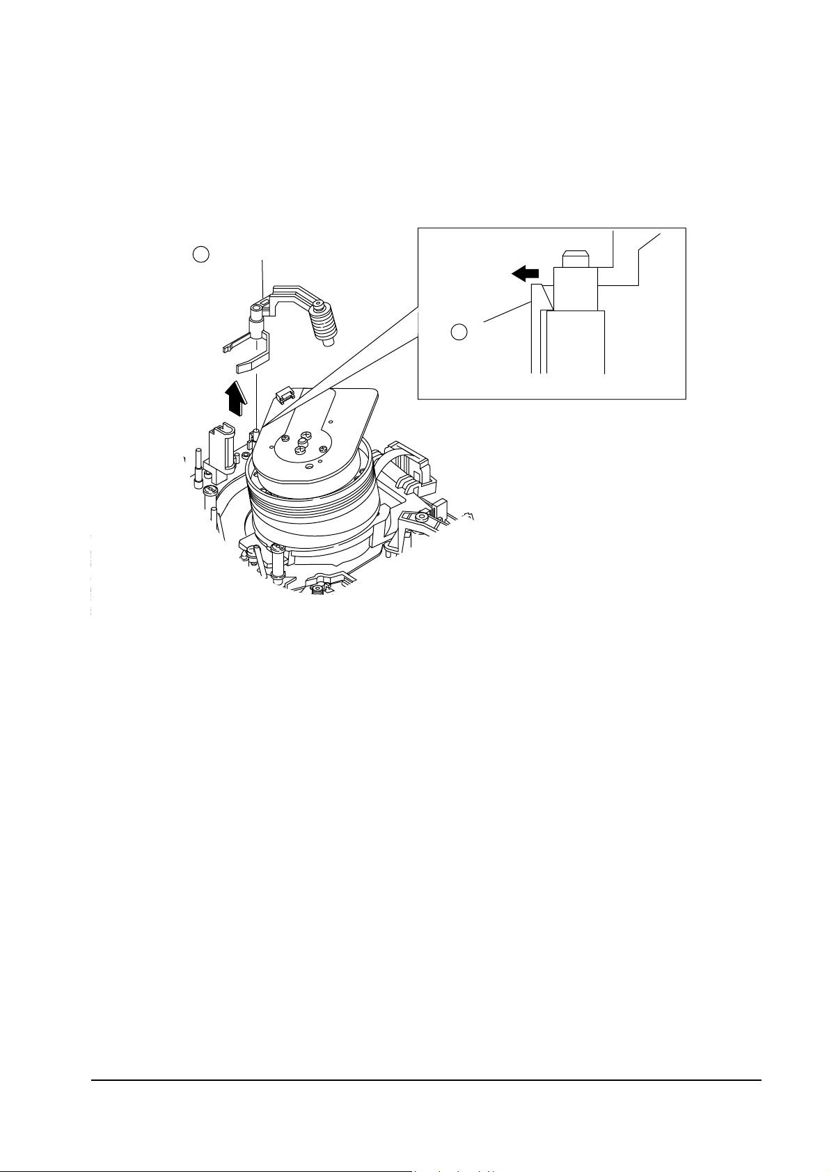
4-3-2 Head Cleaner Ass’y Removal (Only for Deck : DX7-AC/DX8-AC)
1. Release 1 tab ① in the direction of arrow ÒAÓ. (Refer to detail drawing)
2. Lift the Head Cleaner ➁ in the direction of arrow ÒBÓ.
ASS'Y HEAD CLEANER
"B"
2
TAB
<DETAIL>
"A"
1
Fig. 4-12 Head Cleaner Ass’y Removal
Alignments and Adjustments (Mechanical)
Samsung Electronics 4-13
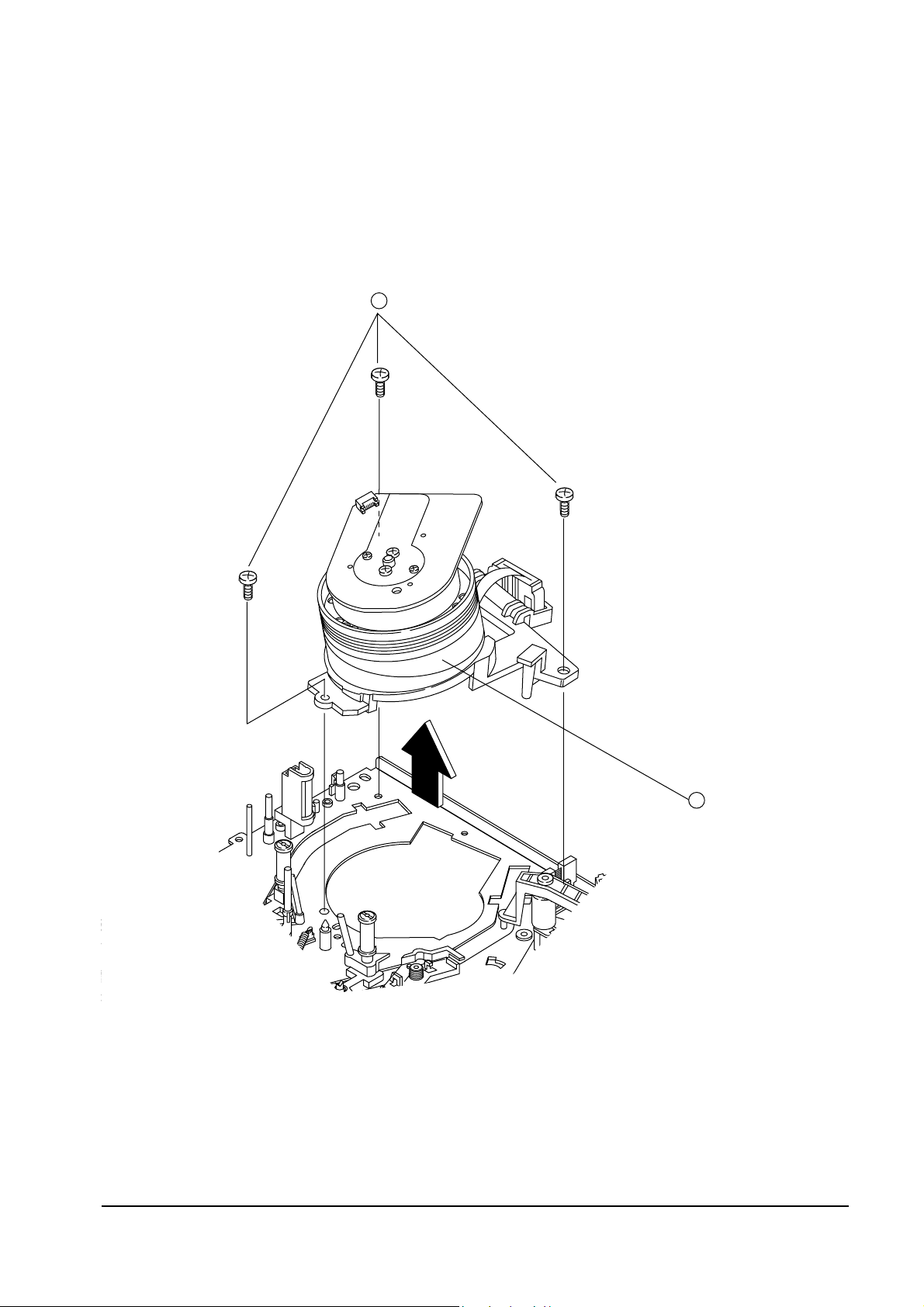
4-3-3 Cylinder Ass’y Removal from Main Base
1. Remove 3 Screws ① holding the Main Base and the Cylinder AssÕy.
2. Lift the Cylinder AssÕy ➁in the direction of arrow.
Note : Do not touch the video heads during removal or installation.
3 SCREWS
1
CYLINDER ASS'Y
2
Fig. 4-13 Cylinder Ass’y Removal from Main Base
Alignments and Adjustments (Mechanical)
4-14
Samsung Electronics
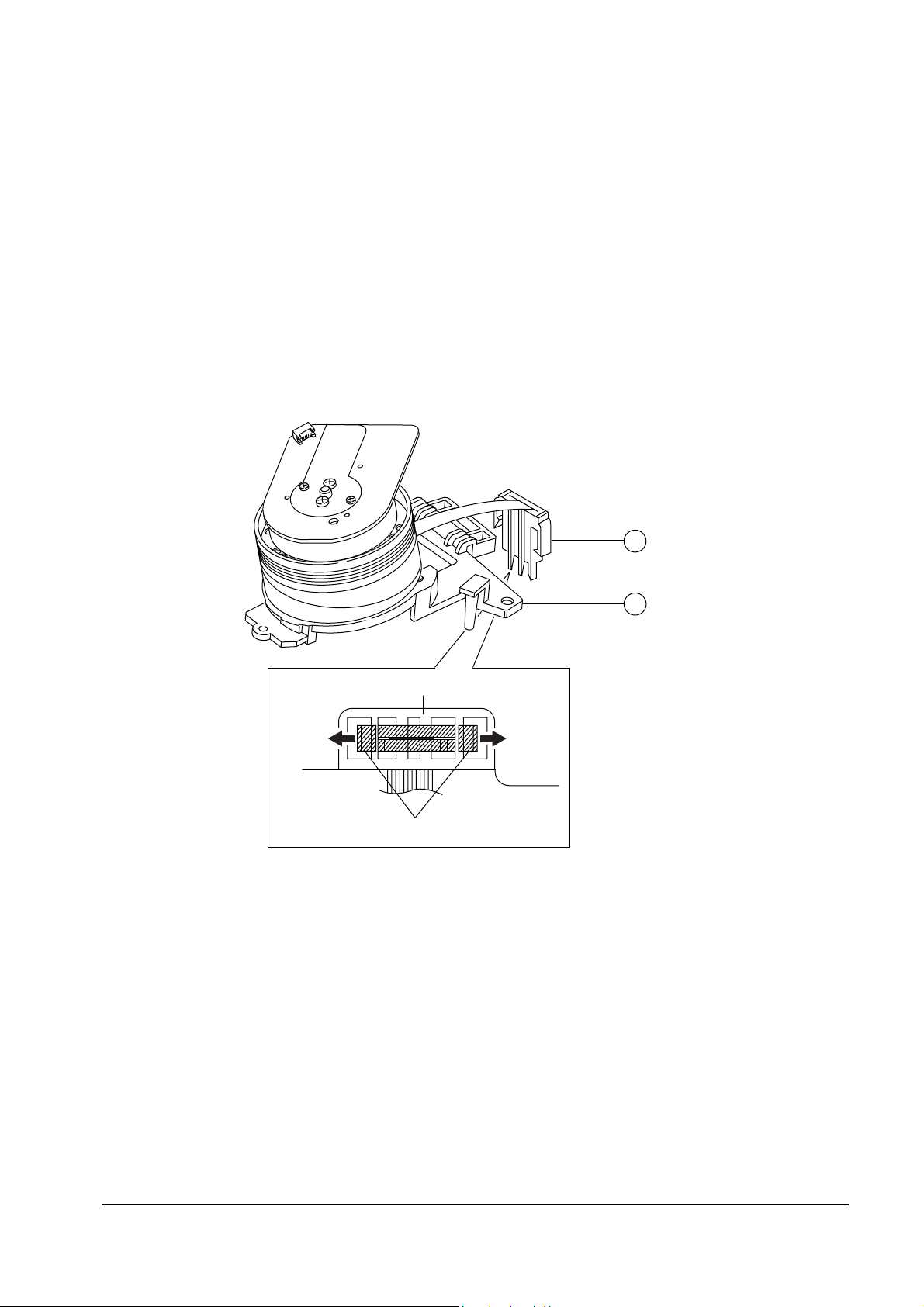
4-3-4 Holder FPC Removal
1. Release the Holder FPC tab holding the Cylinder Base ➁ in the direction of arrow.
(Refer to detail drawing)
2. Disconnect the Holder FPC ① from the Cylinder Base ➁.
3. Note : When disconnecting the FPC Holder ① from the Cylinder Base ➁ :
Take care not to disconnect the FPC cable from the FPC Holder (The FPC cable is very short).
HOLDER FPC
CYLINDER BASE
CYLINDER BASE
HOLDER FPC
<DETAIL : BOTTOM VIEW>
2
1
Fig. 4-14 Head Brush and Holder FPC Removal
Alignments and Adjustments (Mechanical)
Samsung Electronics 4-15
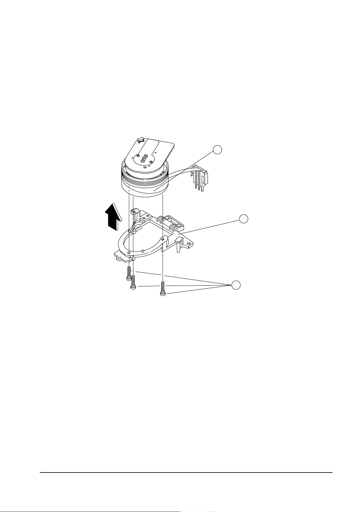
CYLINDER SUB ASS'Y
CYLINDER BASE
3 SCREWS
2
1
3
Fig. 4-15 Cylinder Ass’y Removal from Cylinder Base
4-3-5 Cylinder Ass’y Removal from Cylinder Base
1. Remove 3 Screws ① from the Cylinder Base ➁.
2. Lift the Cylinder AssÕy ➂ from the Cylinder Base ➁ in the direction of arrow.
Alignments and Adjustments (Mechanical)
4-16
Samsung Electronics
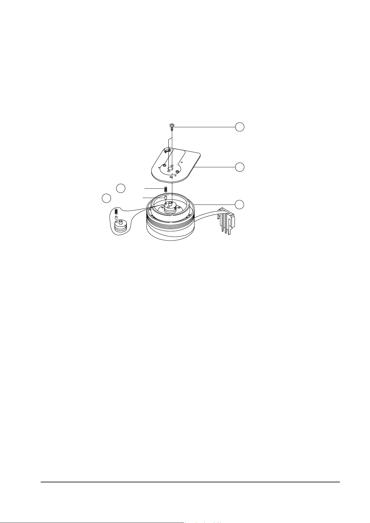
4-3-6 Motor Stator Removal
1. Remove 2 Screws ①.
2. Remove the Motor Stator ➁ from the Cylinder Sub AssÕy ➄.
3. Note : When disassembling the Motor-Stator, be careful not to loose the carbon-tip and spring.
MOTOR - STATOR
CYLINDER SUB ASS'Y
2
2SCREWS
1
5
SPRING
CARBON TIP
3
4
Fig. 4-16 Motor Stator Removal
Alignments and Adjustments (Mechanical)
Samsung Electronics 4-17
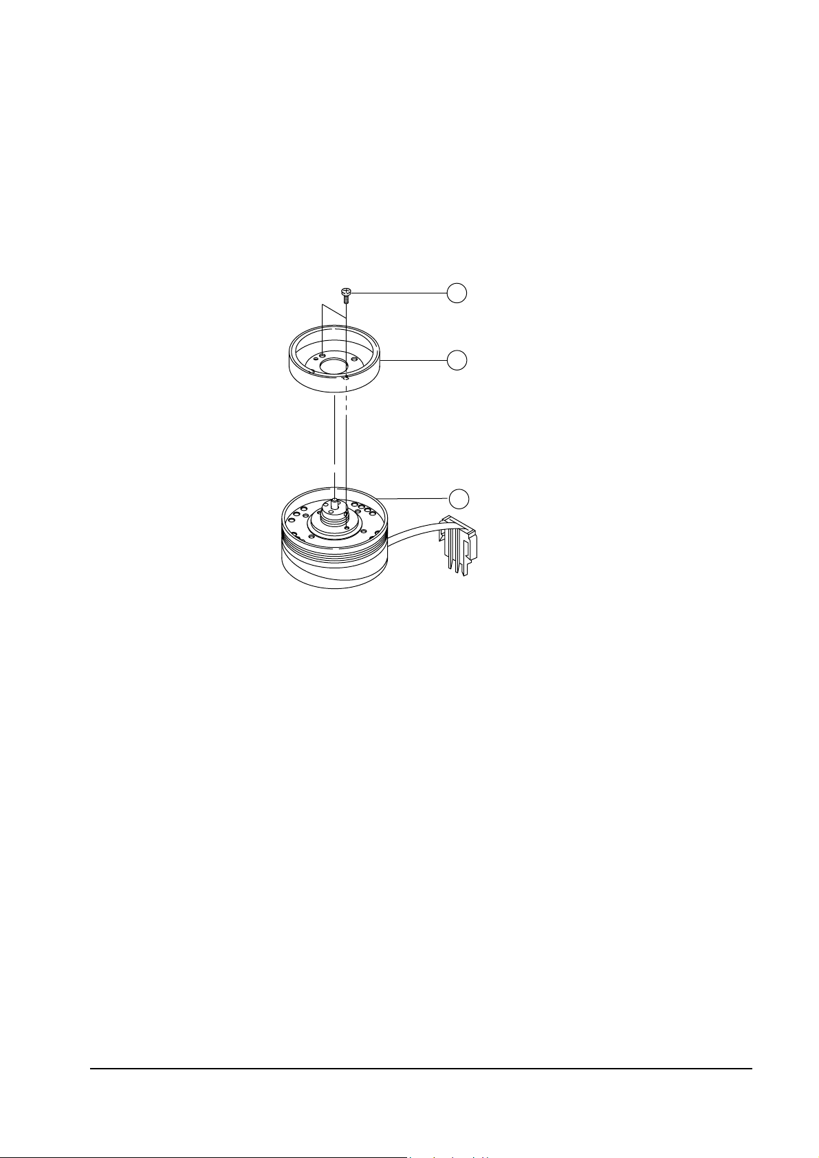
4-3-7 Motor Rotor Removal
1. Remove 2 Screws ①.
2. Lift The Motor Rotor②.
MOTOR - ROTOR
DRUM SUB ASS'Y
2
3
2 SCREWS
1
Fig. 4-17 Motor Rotor Removal
Alignments and Adjustments (Mechanical)
4-18
Samsung Electronics
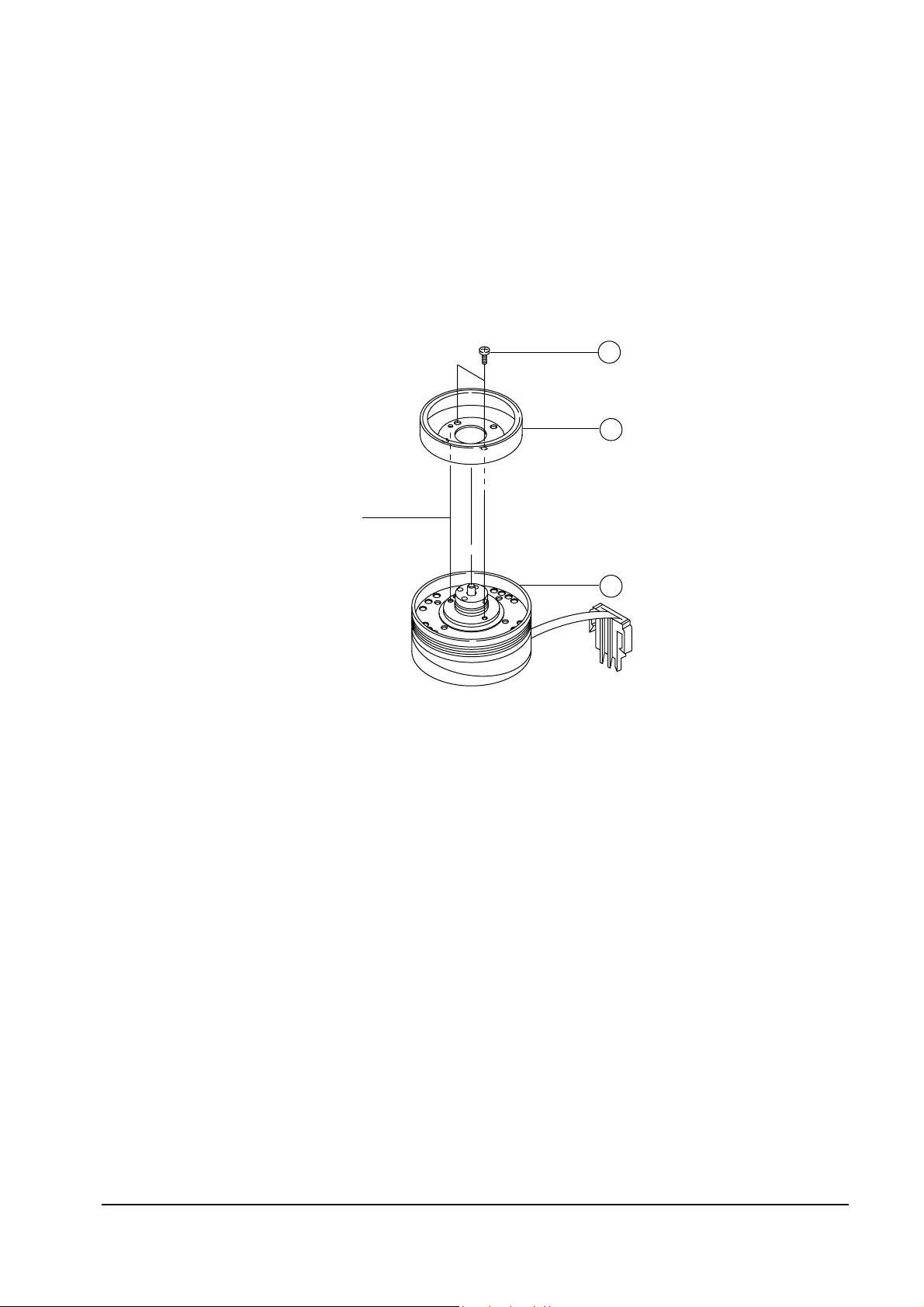
4-3-8 Motor Rotor and Cylinder Sub Ass’y
1. Make sure that phase matching holes of the Motor Rotor and the Cylinder Sub AssÕy are aligned
correctly as shown in Fig. 4-18 (Refer to phase matching hole).
2. Secure 2 Screws.
MOTOR - ROTOR
PHASE MATCHING HOLE
DRUM SUB ASS'Y
2
3
2 SCREWS
1
Fig. 4-18 Assembly of Motor Rotor and Cylinder Sub Ass’y
Alignments and Adjustments (Mechanical)
Samsung Electronics 4-19
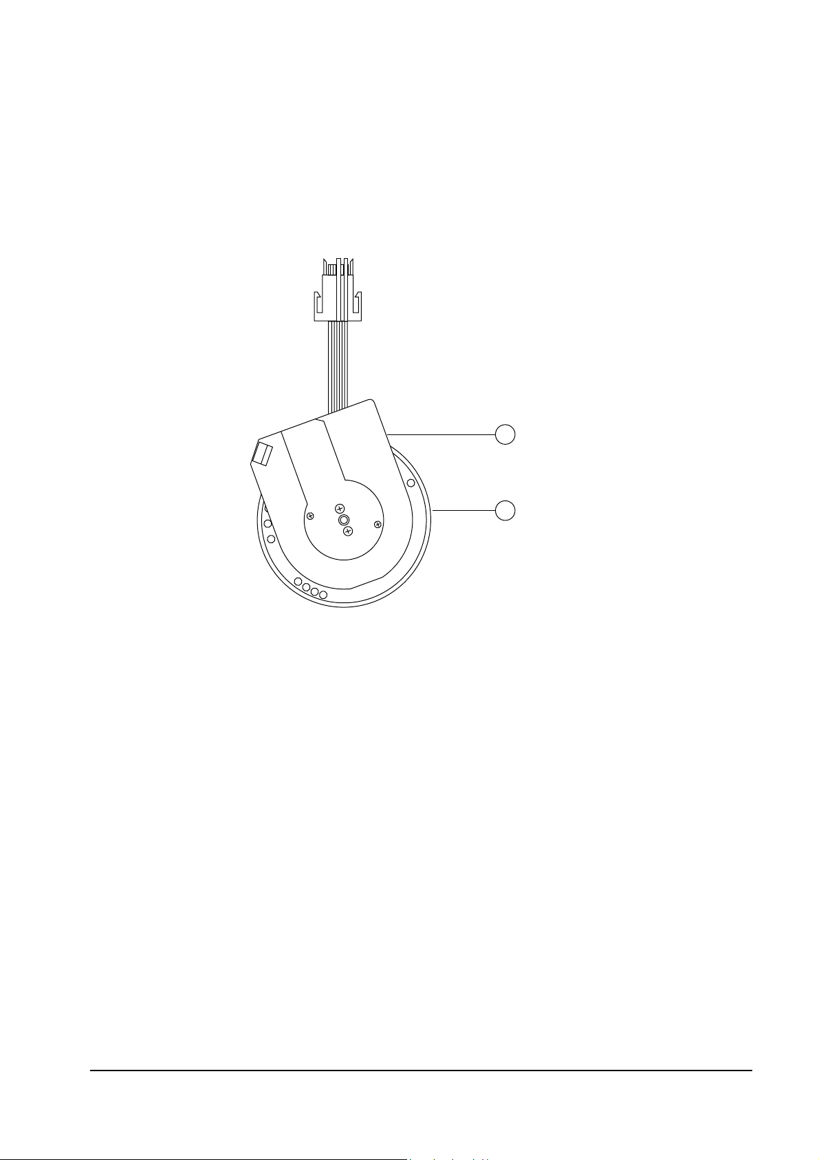
4-3-9 Motor Stator and Cylinder Sub Ass’y
1. Reinstall the Motor Stator ① toward the FPC cable of Cylinder Sub AssÕy ➁.
2. Secure 2 Screws. (Refer to Fig. 4-16)
MOTOR - STATOR
CYLINDER SUB ASS'Y
1
2
Fig. 4-19 Assembly of Motor Stator and Cylinder Sub Ass’y
Alignments and Adjustments (Mechanical)
4-20
Samsung Electronics
4-4 Main Deck Removal and Reassembly
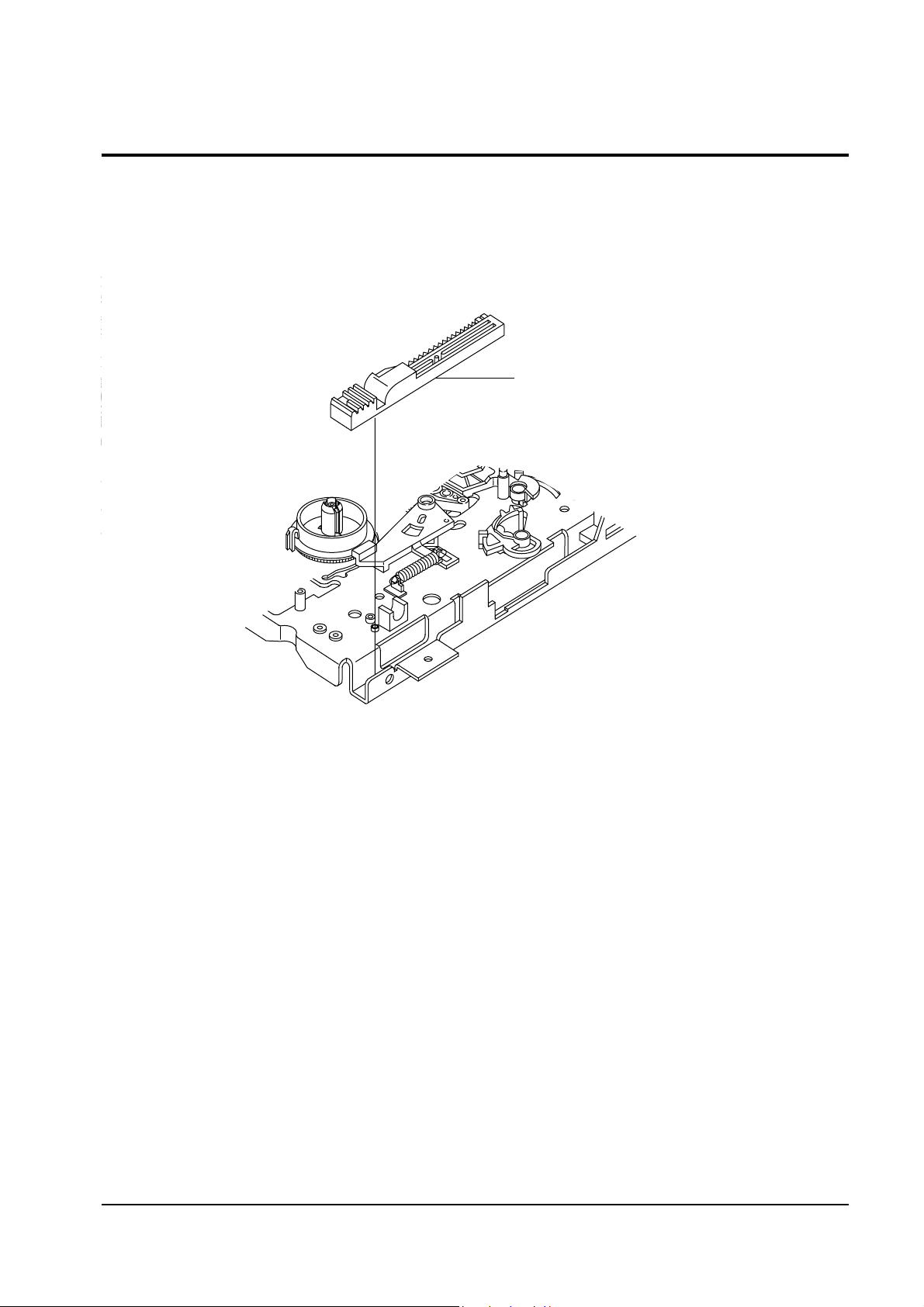
4-4-1 Slide Rack Housing Removal
1. Lift the Slide Rack Housing.
SLIDE RACK HOUSING
Fig. 4-20 Slide Rack Housing Removal
Alignments and Adjustments (Mechanical)
Samsung Electronics 4-21
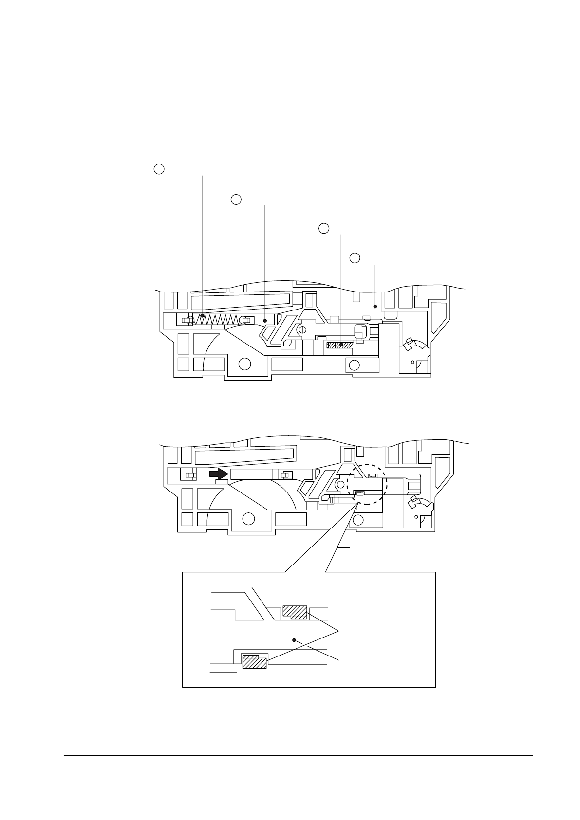
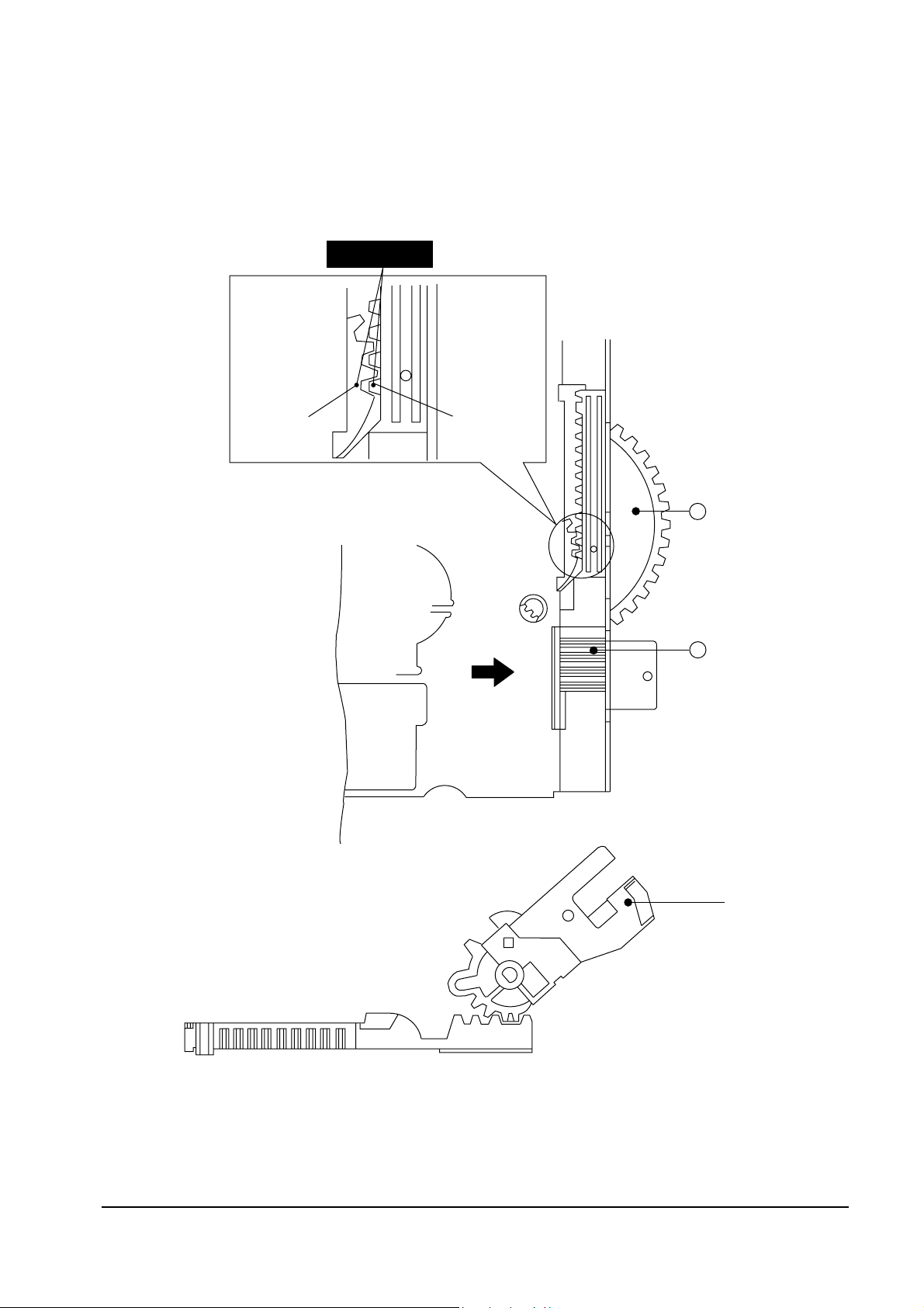
4-4-2 Assembly of Slide Rack Housing and Master Gear
1. Confirm that the hole of Master Gear ① and the hole ÒAÓ of Main Base are aligned correctly. (Eject mode)
2. Align the Slot #1 of Master Gear ①with the Tooth #1 of Rack Housing Slide ➁. (Refer to timing point)
(SLIDE VIEW)
DETAIL
A
TIMING POINT
SLOT #1
TOOTH #1
GEAR MASTER
( TOP VIEW )
( SIDE VIEW )
1
SLIDER RACK
HOUSING
ARM " R"
2
Fig. 4-21 Assembly of Slide Rack Housing and Gear Master
Alignments and Adjustments (Mechanical)
4-22
Samsung Electronics
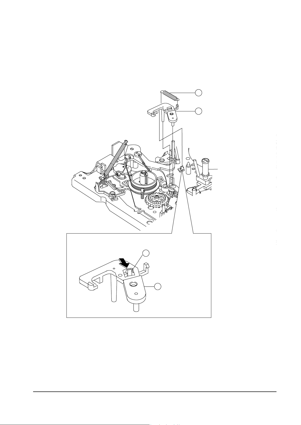
4-4-3 Brake Sub “L” Removal
1. Remove the Sub ÒLÓ Brake Spring ①.
2. Release the tab ➁ in the direction of arrow. (Refer to detail drawing)
3. Lift the Sub ÒLÓ Brake ➂.
<DETAIL>
BRAKE SUB "L"3
TAB2
SPRING-BRAKE SUB "L"1
BRAKE SUB "L"3
Fig. 4-22 Brake Sub “L” Removal
Alignments and Adjustments (Mechanical)
Samsung Electronics 4-23
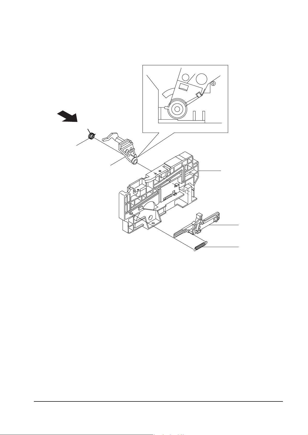
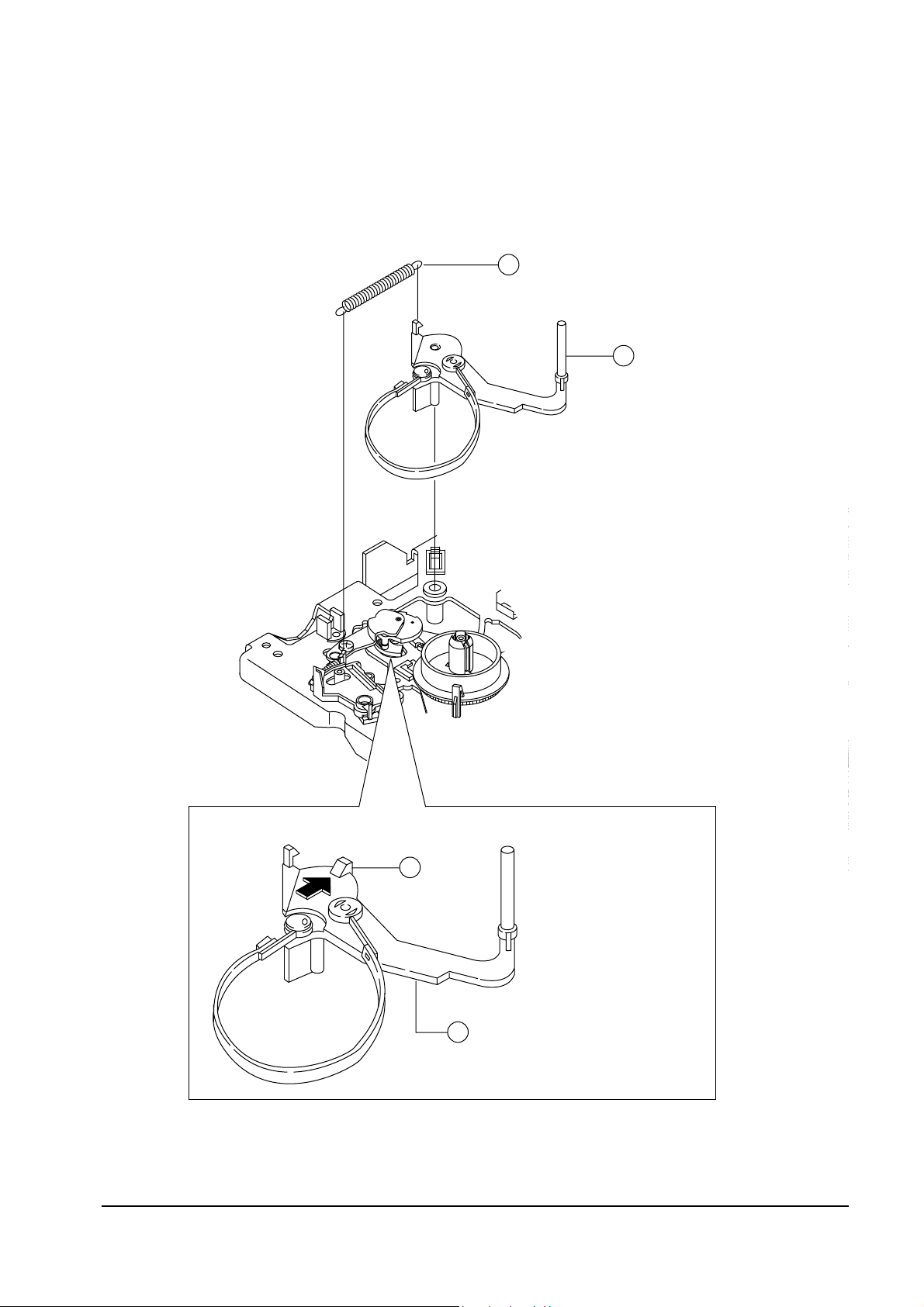
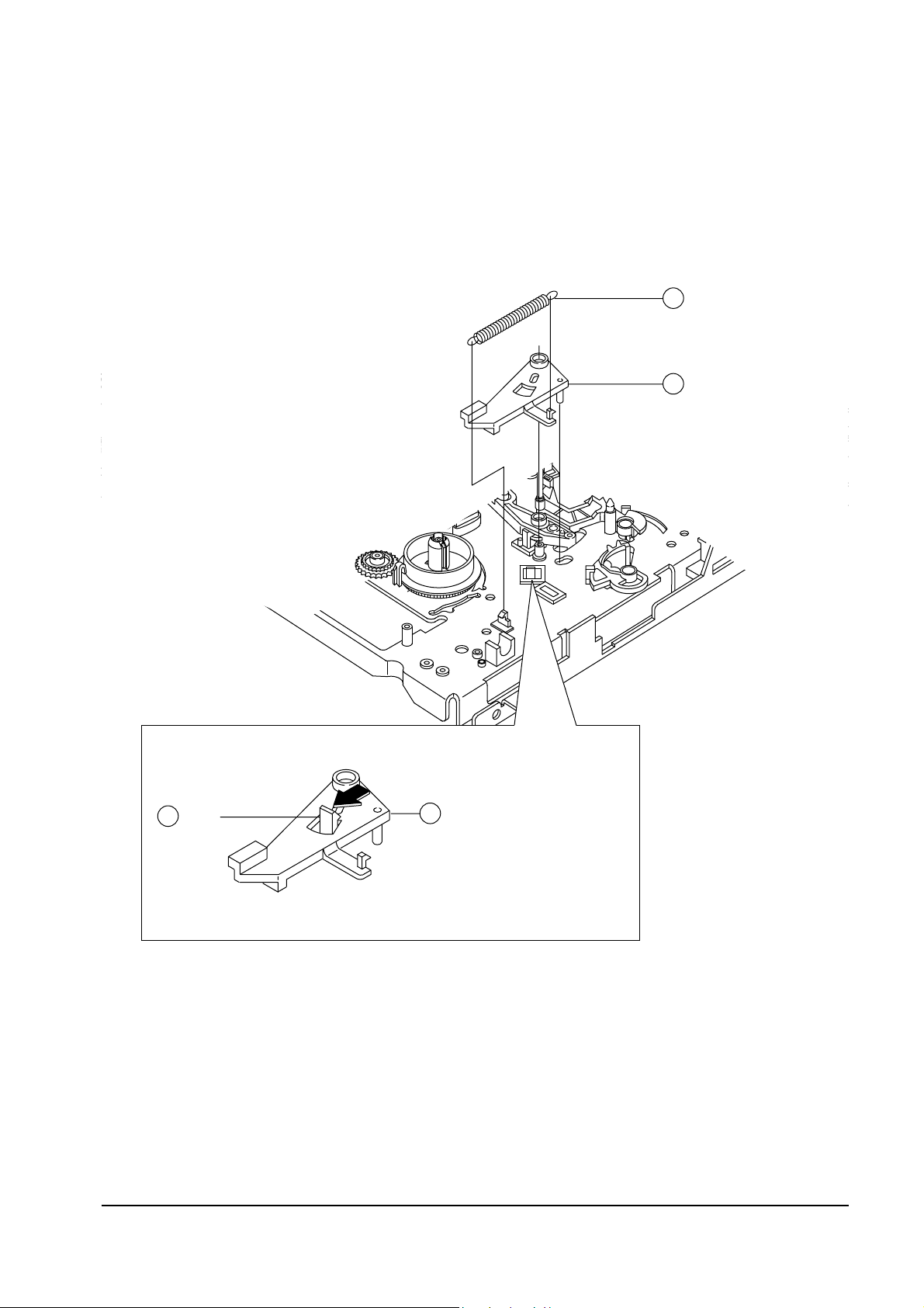
4-4-4 Tension Arm Full Ass’y Removal
1. Remove the Tension Spring ①.
2. Release the tab ➁ in the direction of arrow. (Refer to detail drawing)
3. Lift the Tension Arm Full AssÕy ➂.
<DETAIL>
SPRING TENSION1
TENSION ARM FULL ASS'Y3
TAB2
TENSION ARM FULL ASS'Y 3
Fig. 4-23 Tension Arm Full Ass’y Removal
Alignments and Adjustments (Mechanical)
4-24
Samsung Electronics
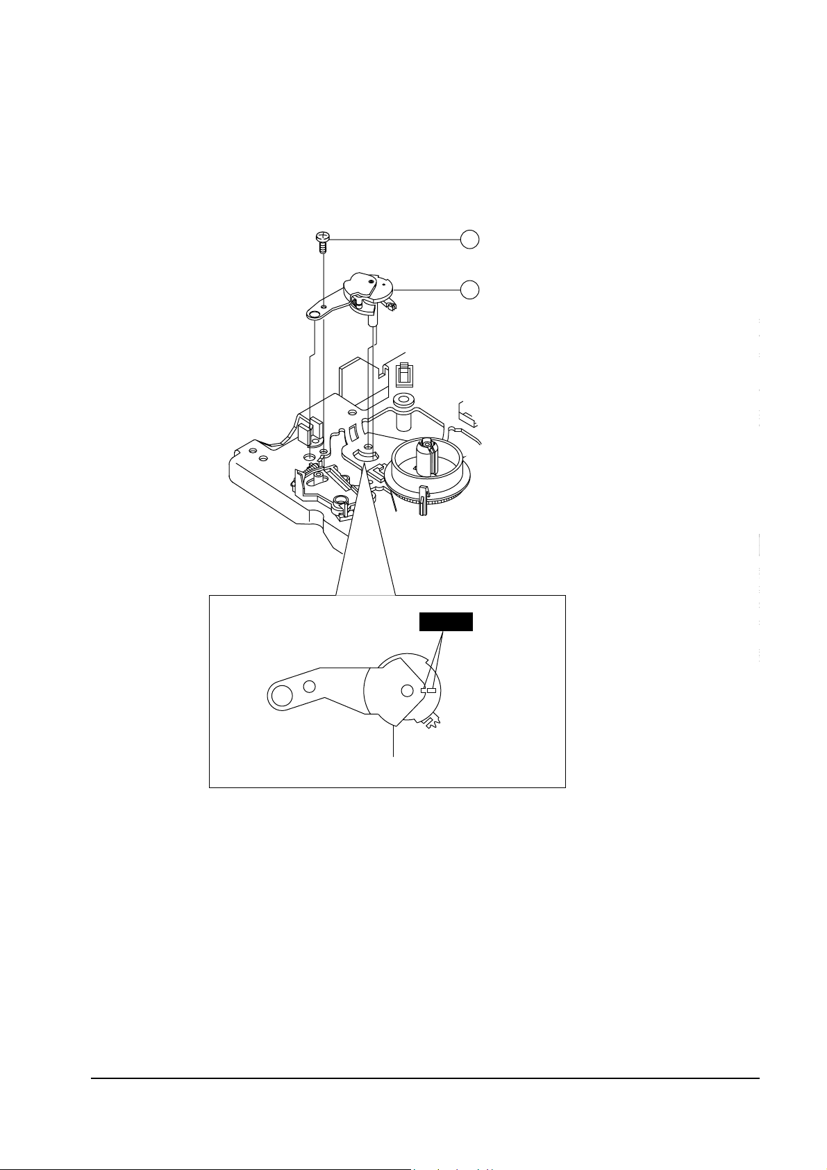
4-4-5 JOG LEVER Ass’y Removal (Only for deck : DX8-A/DX8-AC)
1. Remove the 1 Screw ①.
2. Lift the JOG Lever AssÕy ➁.
<TOP VIEW>
1 SCREW1
JOG LEVER ASS'Y
LEVER JOG ASS'Y
2
TIMING
Fig. 4-24 JOG Lever Ass’y Removal
Alignments and Adjustments (Mechanical)
Samsung Electronics 4-25
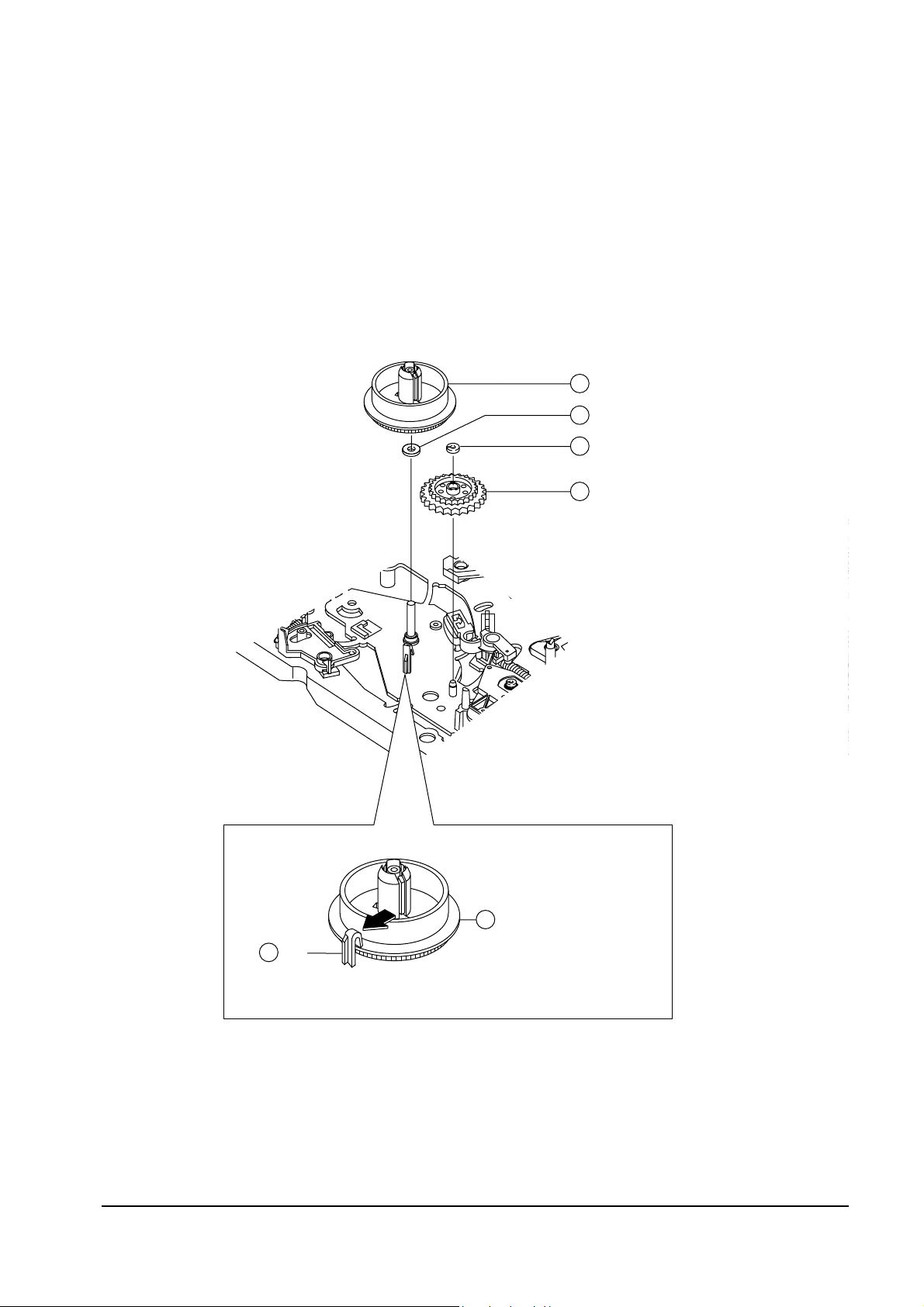
4-4-6 Relay Gear “S” and Reel Disk “L” Removal
1. Release the tab ① in the direction of arrow. (Refer to detail drawing)
2. Lift the Reel Disk ÒLÓ ➁.
3. Remove the Plain Washer ➂.
4. Remove the Slit Washer ➃.
5. Lift the Relay ÒSÓ Gear AssÕy ⑤.
6. Note : When reinstalling, be sure to install the Reel Disk ÒLÓ ✠ after installing the Plain Washer.
<DETAIL>
REEL-DISK "L" 2
TAB
1
WASHER-PLAIN3
REEL-DISK "L" 2
WASHER-SLIT4
GEAR-RELAY "S" ASS'Y5
Fig. 4-25 Reel Disk “L” and Gear Relay “S” Ass’y Removal
Alignments and Adjustments (Mechanical)
4-26
Samsung Electronics
4-4-7 Sub Brake “R” Ass’y Removal
1. Remove the Sub ÒRÓ Brake Spring ①.
2. Release the tab ➁ in the direction of arrow. (Refer to detail drawing)
3. Lift the Brake Sub ÒRÓ AssÕy ➂.
SPRING-SUB BRAKE "R"1
SUB-BRAKE "R" ASS'Y3
SUB-BRAKE "R" ASS'Y
<DETAIL>
3
TAB2
Fig. 4-26 Sub Brake “R” Ass’y Removal
Alignments and Adjustments (Mechanical)
Samsung Electronics 4-27
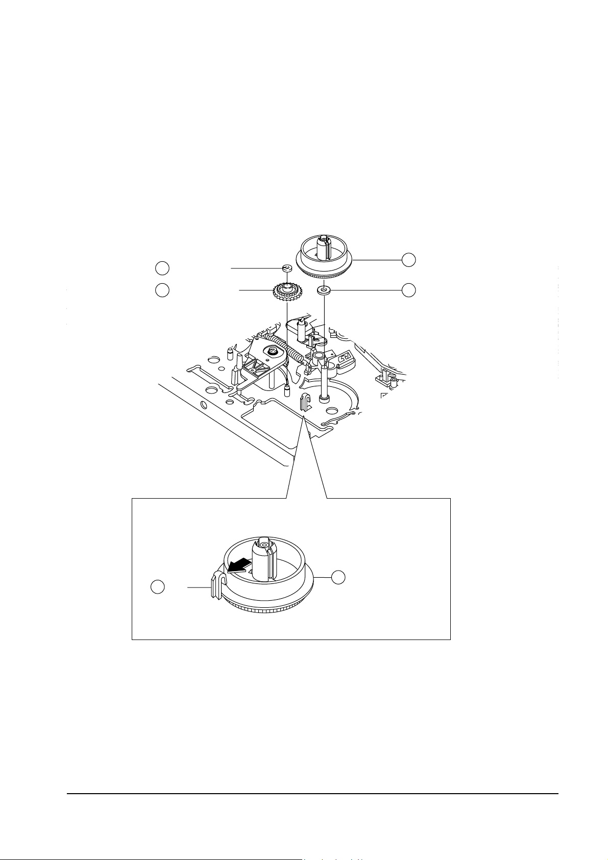
4-4-8 Reel Disk “R” Ass’y and Relay “T”Gear Removal
1. Release the tab ① in the direction of arrow. (Refer to detail drawing)
2. Lift the Reel Disk ÒRÓ AssÕy ➁.
3. Remove the Plain Washer ➂.
4. Remove the Slit Washer ➃.
5. Lift the Relay ÒTÓ Gear AssÕy ➄.
Note : When reinstalling, be sure to install the Reel Disk ÒRÓ AssÕy ✠ after installing the Plain Washer ➂.
REEL-DISK "R" ASS'Y
<DETAIL>
2
TAB1
REEL-DISK "R" ASS'Y2
WASHER-PLAIN3GEAR-RELAY "T"5
WASHER-SLIT4
Fig. 4-27 Reel Disk “R” Ass’y and Gear Relay “T” Removal
 Loading...