

Samsung TB14A53X/XSA, TB20A53/XSA Schematic
Television Video Cassette Recorder
Chassis : C15C
Model : TB14A53X/XSA
TB20A53X/XSA
Television Video Cassette Recorder CONTENTS
Precautions
Specifications
Disassembly and Reassembly
Alignment and Adjustment (Mechanical)
Alignment and Adjustment (Electrical)
Troubleshooting
Exploded View and Parts List
Electrical Parts List
Block Diagram
Wiring Diagram
Schematic Diagrams
1.
2.
3.
4.
5.
6.
7.
8.
9.
10.
11.

ELECTRONICS
© Samsung Electronics Co., Ltd. Jan.2001
Printed in Korea
3C15C-1401
1. Precautions
1-1 Safety Precautions
1. Be sure that all of the built-in protective
devices are replaced. Restore any missing
protective shields.
2. When reinstalling the chassis and its
assemblies, be sure to restore all protective
devices, including: nonmetallic control knobs
and compartment covers.
3. Make sure that there are no cabinet openings
through which people—particularly
children—might insert fingers and contact
dangerous voltages. Such openings include
the spacing between the picture tube and the
cabinet mask, excessively wide cabinet
ventilation slots, and improperly fitted back
covers.
If the measured resistance is less than 1.0
megohm or greater than 5.2 megohms, an
abnormality exists that must be corrected
before the unit is returned to the customer.
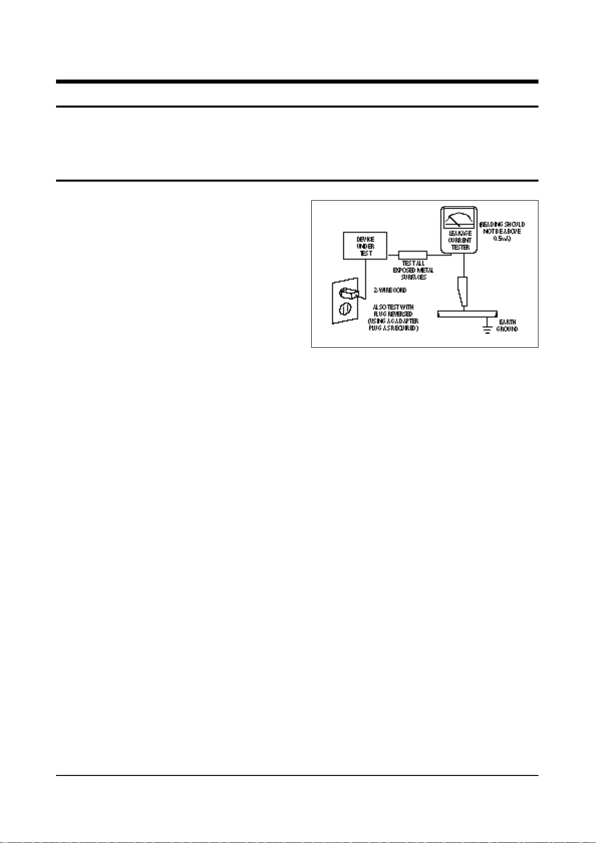
4. Leakage Current Hot Check (Figure 1-1):
Warning: Do not use an isolation
transformer during this test. Use a leakagecurrent tester or a metering system that
complies with American National Standards
Institute (ANIS C101.1, Leakage Current for
Appliances), and Underwriters Laboratories
(UL Publication UL1410, 59.7).
5. With the unit completely reassembled, plug
the AC line cord directly into the power
outlet. With the unit’s AC switch first in the
ON position and then OFF, measure the
current between a known earth ground (metal
water pipe, conduit, etc.) and all exposed
metal parts, including: antennas, handle
brackets, metal cabinets, screwheads and
control shafts. The current measured should
not exceed 0.5 milliamp. Reverse the powerplug prongs in the AC outlet and repeat the
test.
Fig. 1-1 AC Leakage Test
6. Antenna Cold Check:
With the unit’s AC plug disconnected from the
AC source, connect an electrical jumper across
the two AC prongs. Connect one lead of the
ohmmeter to an AC prong. Connect the other
lead to the coaxial connector.
7. X-ray Limits:
The picture tube is especially designed to prohibit X-ray emissions. To ensure continued
X-ray protection, replace the picture tube only
with one that is the same type as the original.
Carefully reinstall the picture tube shields and
mounting hardware; these also provide X-ray
protection.
8. High Voltage Limits:
High voltage must be measured each time servicing is done on the B+, horizontal deflection
or high voltage circuits. Correct operation of
the X-ray protection circuits must be
reconfirmed whenever they are serviced.
(X-ray protection circuits also may be called
“horizontal disable” or “hold-down”.)
Heed the high voltage limits. These include
the X–ray Protection Specifications Label, and
the Product Safety and X-ray Warning Note on
the service data schematic.
Precautions
Samsung Electronics 1-1
Follow these safety, servicing and ESD precautions to prevent damage and protect against potential
hazards such as electrical shock and X-rays.

1-1 Safety Precautions (Continued)
9. High voltage is maintained within specified
limits by close-tolerance, safety-related
components and adjustments. If the high
voltage exceeds the specified limits, check
each of the special components.
10. Design Alteration Warning:
Never alter or add to the mechanical or
electrical design of this unit. Example: Do not
add auxiliary audio or video connectors. Such
alterations might create a safety hazard. Also,
any design changes or additions will void the
manufacturer’s warranty.
11. Hot Chassis Warning:
Some TV receiver chassis are electrically
connected directly to one conductor of the AC
power cord. If an isolation transformer is not
used, these units may be safely serviced only
if the AC power plug is inserted so that the
chassis is connected to the ground side of the
AC source.
To confirm that the AC power plug is inserted
correctly, do the following: Using an AC
voltmeter, measure the voltage between the
chassis and a known earth ground. If the
reading is greater than 1.0V, remove the AC
power plug, reverse its polarity and reinsert.
Re-measure the voltage between the chassis
and ground.
12. Some TV chassis are designed to operate with
85 volts AC between chassis and ground,
regardless of the AC plug polarity. These units
can be safely serviced only if an isolation
transformer inserted between the receiver and
the power source.
13. Some TV chassis have a secondary ground
system in addition to the main chassis ground.
This secondary ground system is not
isolated from the AC power line. The two
ground systems are electrically separated by
insulating material that must not be defeated
or altered.
14. Components, parts and wiring that appear to
have overheated or that are otherwise
damaged should be replaced with parts that
meet the original specifications. Always
determine the cause of damage or overheating, and correct any potential hazards.
15. Observe the original lead dress, especially
near the following areas: Antenna wiring,
sharp edges, and especially the AC and high
voltage power supplies. Always inspect for
pinched, out-of-place, or frayed wiring. Do
not change the spacing between components
and the printed circuit board. Check the AC
power cord for damage. Make sure that leads
and components do not touch thermally hot
parts.
16. Picture Tube Implosion Warning:
The picture tube in this receiver employs
“integral implosion” protection. To ensure
continued implosion protection, make sure
that the replacement picture tube is the same
as the original.
17. Do not remove, install or handle the picture
tube without first putting on shatterproof
goggles equipped with side shields. Never
handle the picture tube by its neck. Some
“in-line” picture tubes are equipped with a
permanently attached deflection yoke; do not
try to remove such “permanently attached”
yokes from the picture tube.
18. Product Safety Notice:
Some electrical and mechanical parts have
special safety-related characteristics which
might not be obvious from visual inspection.
These safety features and the protection they
give might be lost if the replacement component differs from the original—even if the
replacement is rated for higher voltage,
wattage, etc.
Components that are critical for safety are
indicated in the circuit diagram by shading,
( ) or ( ).
Use replacement components that have the
same ratings, especially for flame resistance
and dielectric strength specifications.
A replacement part that does not have the
same safety characteristics as the original
might create shock, fire or other hazards.
Precautions
1-2 Samsung Electronics

1-2 Servicing Precautions
1. Servicing precautions are printed on the
cabinet. Follow them.
2. Always unplug the unit’s AC power cord from
the AC power source before attempting to: (a)
Remove or reinstall any component or
assembly, (b) Disconnect an electrical plug or
connector, (c) Connect a test component in
parallel with an electrolytic capacitor.
3. Some components are raised above the printed
circuit board for safety. An insulation tube or
tape is sometimes used. The internal wiring is
sometimes clamped to prevent contact with
thermally hot components. Reinstall all such
elements to their original position.
4. After servicing, always check that the screws,
components and wiring have been correctly
reinstalled. Make sure that the portion around
the serviced part has not been damaged.
5. Check the insulation between the blades of the
AC plug and accessible conductive parts
(examples: metal panels, input terminals and
earphone jacks).
6. Insulation Checking Procedure: Disconnect the
power cord from the AC source and turn the
power switch ON. Connect an insulation
resistance meter (430V) to the blades of the AC
plug.
The insulation resistance between each blade
of the AC plug and accessible conductive parts
(see above) should be greater than 1 megohm.
7. Never defeat any of the B+ voltage interlocks.
Do not apply AC power to the unit (or any of
its assemblies) unless all solid-state heat sinks
are correctly installed.
8. Always connect a test instrument’s ground
lead to the instrument chassis ground before
connecting the positive lead; always remove
the instrument’s ground lead last.
Precautions
Samsung Electronics 1-3
Warning1: First read the “Safety Precautions” section of this manual. If some unforeseen circumstance creates a conflict between
the servicing and safety precautions, always follow the safety precautions.
Warning2: An electrolytic capacitor installed with the wrong polarity might explode.

1. Some semiconductor (“solid state”) devices
are easily damaged by static electricity. Such
components are called Electrostatically
Sensitive Devices (ESDs); examples include
integrated circuits and some field-effect
transistors. The following techniques will
reduce the occurrence of component damage
caused by static electricity.
2. Immediately before handling any semicon
ductor components or assemblies, drain the
electrostatic charge from your body by
touching a known earth ground. Alternatively,
wear a discharging wrist-strap device. (Be
sure to remove it prior to applying power—
this is an electric shock precaution.)
3. After removing an ESD-equipped assembly,
place it on a conductive surface such as
aluminum foil to prevent accumulation of
electrostatic charge.
4. Do not use freon-propelled chemicals. These
can generate electrical charges that damage
ESDs.
5. Use only a grounded-tip soldering iron when
soldering or unsoldering ESDs.
6. Use only an anti-static solder removal device.
Many solder removal devices are not rated as
“anti-static”; these can accumulate sufficient
electrical charge to damage ESDs.
7. Do not remove a replacement ESD from its
protective package until you are ready to
install it. Most replacement ESDs are
packaged with leads that are electrically
shorted together by conductive foam,
aluminum foil or other conductive materials.
8. Immediately before removing the protective
material from the leads of a replacement ESD,
touch the protective material to the chassis or
circuit assembly into which the device will be
installed.
9. Minimize body motions when handling
unpackaged replacement ESDs. Motions such
as brushing clothes together, or lifting a foot
from a carpeted floor can generate enough
static electricity to damage an ESD.
Precautions
1-4 Samsung Electronics
1-3 Precautions for Electrostatically Sensitive Devices (ESDs)
Samsung Electronics 2-1
2. Specifications
TELEVISION PART
Colour systems PAL(option) / SECAM(option) (UK;PAL)
TV standards L/L’(option), B/G(option), D/K(option) (UK;I)
Number of channels 100 programmes
Reception range/cable TV Hyperband/interband tuner
Aerial input 75 Ohms, coaxial cable
VCR PART
Format VHS standard
(PAL / SECAM(option) / MESECAM(option) / NTSC in playback only)
Heads Video: 2 rotary heads, LP(option), 4 Heads(option)
Audio/Control: 1 stationary head (linear)
Erase: 1 full track erase head
System Video Normal CCIR
System Audio Mono / NICAM&A2-STEREO
Luminance FM azimuth recording
Colour Down converted subcarrier phase shifted direct recording
FF/REW time Less than 100 seconds in FF with E-120
Wow and flutter (WTD) 0.4% maximum (SP)
Frequency response 100 Hz - 8 KHz
GENERAL
Power supply 220-240V~, 50Hz (110-260V~, 50/60Hz; option)
Consumption 14” (60W)
20”/21” (90W)
Audio output power 14” (1.5W)
20” (3W)
21” (1.5Watts x 2)
Number of loudspeakers 14”/20” (1)
21” (2)
Tube size 14” (37cm/34cmV)
20” (51cm/48cmV)
21” (55cm/51cmV)
Tube type BLACK MATRIX
Sockets 1 full RGB SCART on the rear
1 RCA input (audio and video) on the front
Earphones output (3.5 mm mini-jack)
1 aerial/cable TV coaxial input
Dimensions (W x D x H) 14” (368.5 x 388 x 381)
20” (488 x 477 x 488)
21” (520 x 495 x 508)
Weight 14” (11.7 kg)
20” (20.4 kg)
21” (23.2 kg)
Operating temperature 5°C - 40°C (41°F - 104°F)
Relative humidity 10% - 75%
The descriptions and characteristics given in this booklet are given for information purposes only and
are subject to modification without notice.

MEMO
2-2 Samsung Electronics

5-2 Factory (“Service”) Mode
Alignment and Adjustments (Electrical)
Samsung Electronics 5-1
5. Alignment and Adjustments (Electrical)
5-1 Preadjustment
5-1-1 Factory Mode
1. Do not attempt these adjustments in the Video
Mode.
2. The Factory Mode adjustments are necessary
when either the EEPROM (IC902S) or the CRT
is replaced.
3. Do not tamper with the “Adjustment” screen
of the Factory Mode menu. This screen is
intended only for factory use.
5-1-2 When EEPROM (IC902S) Is Replaced
1. When IC902S is replaced all adjustment data
revert to initial values. It is necessary to reprogram this data.
2. After IC902S is replaced, warm up the TV for
10 seconds.
5-1-3 When CRT Is Replaced
Make the following adjustments after setting up
purity and convergence:
White Balance
Sub-Brightness
Vertical Center
Vertical Size
Horizontal Size
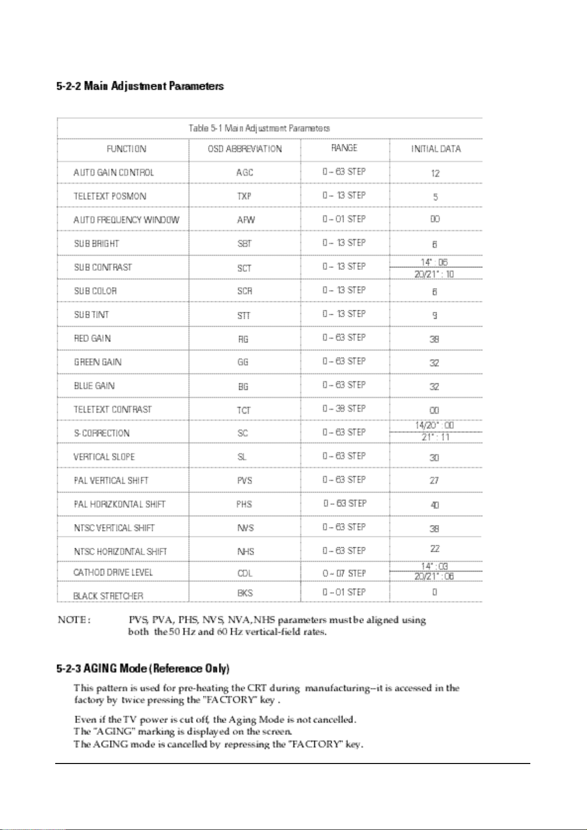
5-2-1 Procedure for the “Adjustment” Mode
1. This mode uses the standard remote control.
The Service Mode is activated by: (1) pressing
the “FACTORY” service key on the local-keyboard, or (2) by entering the following remotecontrol sequence (within 2 seconds):
STAND-BY →DISPLAY →MENU→ MUTE→
POWER ON
2. The “SERVICE (FACTORY)” message will be
displayed. The Service Mode has three components: Adjustment, Option and Reset.
3. Access the Adjustment Mode by pressing the
“VOLUME” keys ( Up or Down). The adjustment parameters are listed in the accompanying table, and selected by pressing the CHAN-
NEL keys (s,t).
4. Selection sequences for the
PAL/SECAM B/G, L/systems:
down or up key:
AGC>TXP>AFW>SBT>SCT>SCR>STT>RG>
GG>BG>TCT>SC>SL>PVS>PHS>NVS>
NHS>CDL>BKS
5. The VOLUME keys increase or decrease the
adjustment values, (stored in the
non-volatile memory) when Adjustment Mode
is cancelled.
Alignment and Adjustments (Electrical)
5-2 Samsung Electronics

Alignment and Adjustments (Electrical)
Samsung Electronics 5-3

Alignment and Adjustments (Electrical)
5-4 Samsung Electronics
5-4 Other Adjustments
5-4-1 General
1. Usually, a color TV needs only slight
touch-up adjustment upon installation.
Check the basic characteristics such as height,
horizontal and vertical sync and focus.
2. The picture should have good black and white
details. There should be no objectionable
color shading; if color shading is present,
perform the purity and convergence adjustments described below.
3. Use the specified test equipment or its
equivalent.
4. Correct impedance matching is essential.
5. Avoid overload. Excessive signal from a sweep
generator might overload the front-end of the
TV. When inserting signal markers, do not
allow the marker generator to distort test
results.
6. Connect the TV only to an AC power source
with voltage and frequency as specified on the
backcover nameplate.
7. Do not attempt to connect or disconnect any
wires while the TV is turned on. Make sure
that the power cord is disconnected before
replacing any parts.
8. To protect against shock hazard, use an
isolation transformer.
5-4-2 Automatic Degaussing
A degaussing coil is mounted around the
picture tube, so that external degaussing after
moving the TV should be unnecessary. But
the receiver must be properly degaussed upon
installation.
The degaussing coil operates for about 1
second after the power is switched ON. If the
set has been moved or turned in a different
direction, disconnect its AC power for at least
10 minutes.
If the chassis or parts of the cabinet become
magnetized, poor color purity will result. If
this happens, use an external degaussing coil.
Slowly move the degaussing coil around the
faceplate of the picture tube and the sides and
front of the receiver. Slowly withdraw the coil
to a distance of about 6 feet before removing
power.
5-4-3 High Voltage Check
CAUTION: There is no high voltage
adjustment on this chassis. The B+ power
supply must be set to +125 volts (Full color
bar input and normal picture level).
1. Connect a digital voltmeter to the second
anode of the picture tube.
2. Turn on the TV. Set the Brightness and
Contrast controls to minimum (zero beam
current).
3. The high voltage should not exceed 27.5KV.
4. Adjust the Brightness and contrast controls to
both extremes. Ensure that the high voltage
does not exceed 27.5KV under any conditions.

Alignment and Adjustments (Electrical)
Samsung Electronics 5-5
5-4-4 FOCUS Adjustment
1. Input a black and white signal.
2. Adjust the tuning control for the clearest picture.
3. Adjust the FOCUS control for well defined scanning lines in the center area of the screen.
5-4-5 Screen Adjustment
1. Turn to the ACTIVE channel.
2. Adjust the VR screen for a normal picture is (no blooming or flyback line).
3. Adjust the FOCUS control for well defined scanning lines in the center area of the screen.
5-4-6 Purity Adjustment
1. Warm up the receiver for at least 20 minutes.
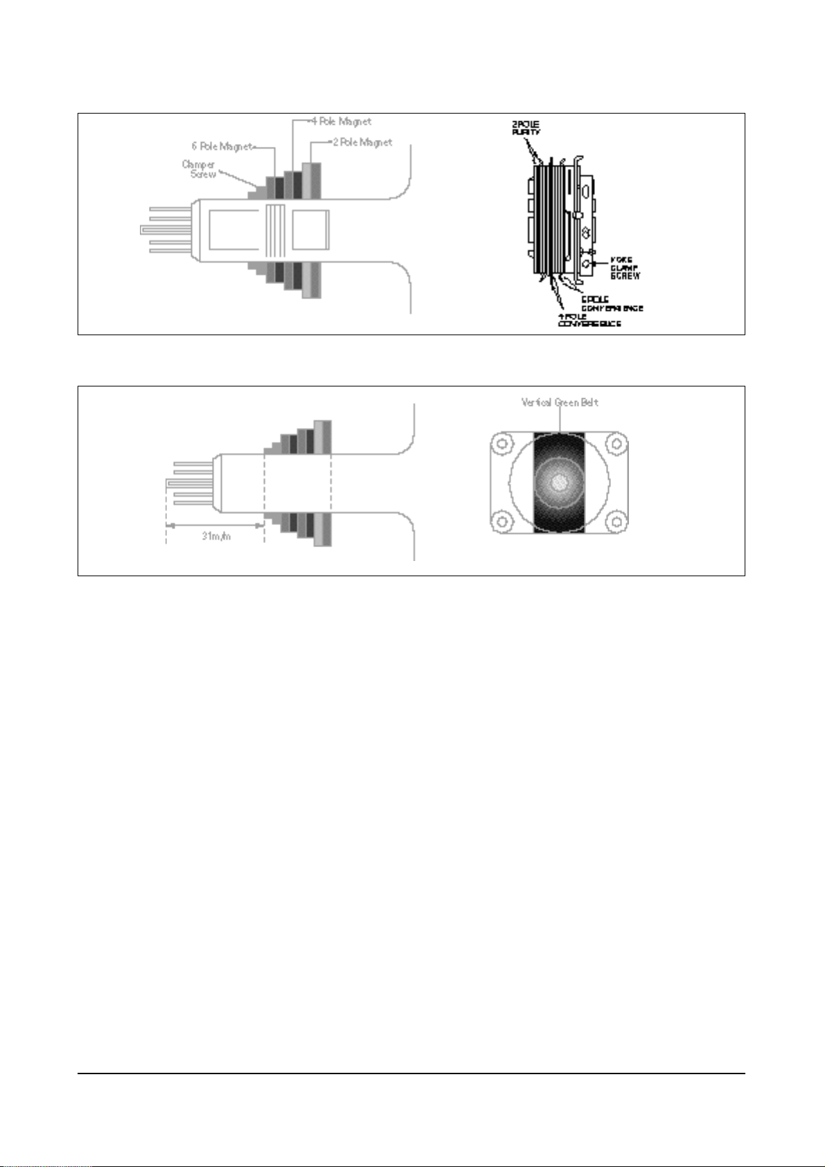
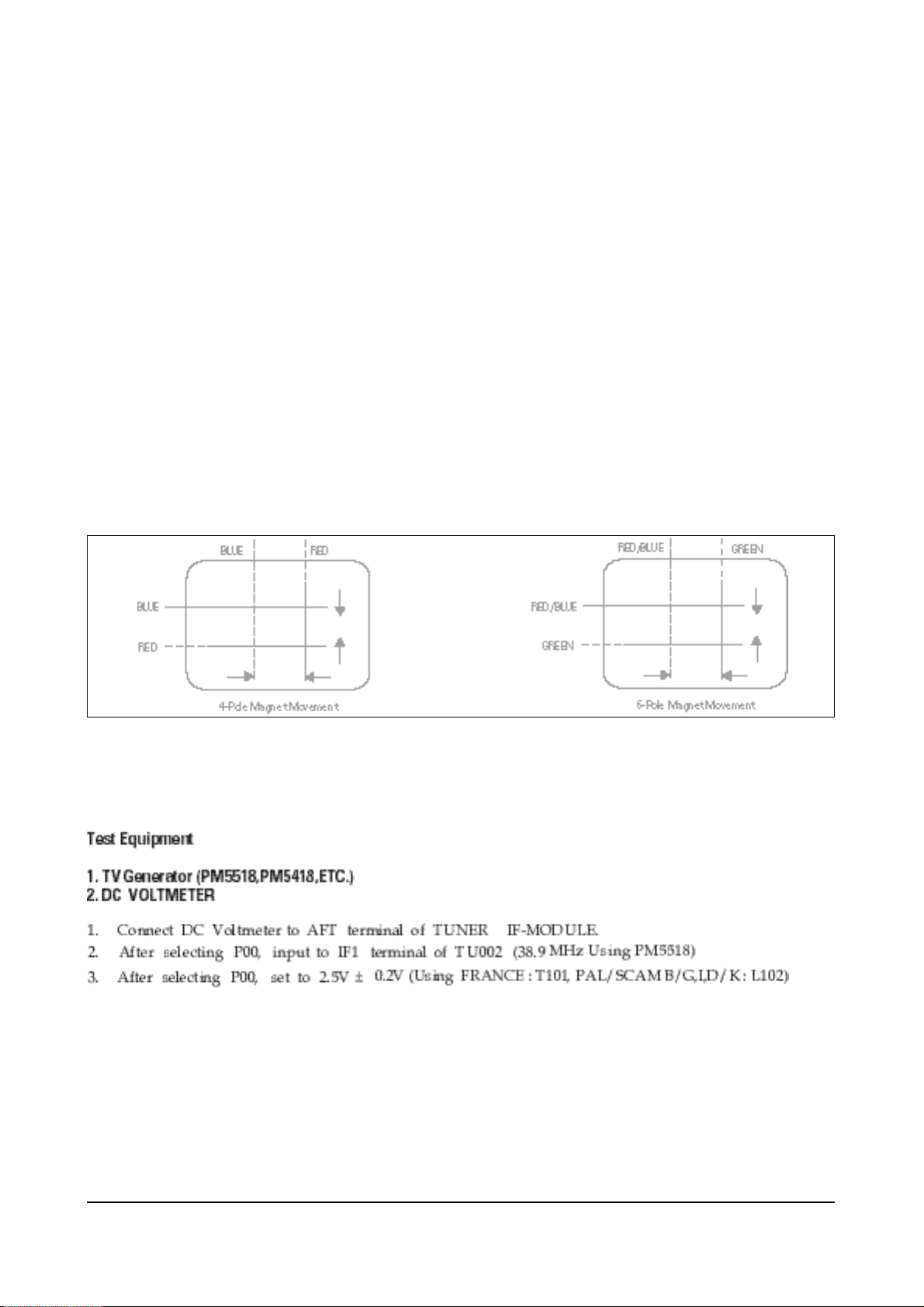
2. Plug in the CRT deflection yoke and tighten the clamp screw.
3. Plug the convergence yoke into the CRT and set in as shown in Fig. 5-1.
4. Input a black and white signal.
5. Fully demagnetize the receive by applying an external degaussing coil.
6. Turn the CONTRAST and BRIGHTNESS controls to maximum.
7. Loosen the clamp screw holding the yoke. Slide the yoke backward or forward to provide
vertical green belt. (Fig. 5-2).
8. Tighten the convergence yoke.
9. Slowly move the deflection yoke forward, and adjust for the best overall green screen.
10. Temporarily tighten the deflection yoke.
11. Produce blue and red rasters by adjusting the low-light controls. Check for good purity
in each field.
12. Tighten the deflection yoke.
Alignment and Adjustments (Electrical)
5-6 Samsung Electronics
5-4-7 White Balance Adjustment
5-4-7 (A) HIGH-LIGHT ADJUSTMENT
1. Input either a Lion Head or a “pure white” pattern.
2. Warm up the TV for 30 minutes.
3. Check the data in the Service Mode
4. Adjust RG, BG in the Factory Mode.
5-4-7 (B) LOW-LIGHT ADJUSTMENT
1. Automatically accomplished during the high-light adjustment.
Fig. 5 -1 Convergence Magnet Assembly
Fig. 5-2 Center Convergence Adjustment
Alignment and Adjustments (Electrical)
Samsung Electronics 5-7
5-4-8 Center Convergence Adjustment
1. Warm up the receiver for at least 20 minutes.
2. Adjust the two tabs of the 4 pole magnets to
change the angle between them. Superimpose
the red and blue vertical lines in the center
area of the screen.
3. Adjust the Brightness and Contrast controls for
a well defined picture.
4. Adjust the two-tab pairs of the 4 pole magnets,
and change the angle between them.
Superimpose the red and the blue vertical
lines in the center area of the screen.
5. Turn the both tabs at the same time, keeping
the angle constant, and superimpose the red
and blue horizontal line in the center of the
screen.
6. Adjust the two-tab pairs of the 6-pole magnets
to superimpose the red and blue line onto the
green. (Changing the angle affects the vertical
lines, and rotating both magnets affects the
horizontal lines.)
7. Repeat adjustments 2~6, if necessary.
8. Since the 4-pole magnets and 6-pole magnets
interact, the dot movement is complex
(Fig. 5-3).
Fig 5-3 Center Convergence Adjustment
5-4-9 Dual Tuner AFT Adjustment
 Loading...