

Samsung TB14A53X/RAD Service Manual

Television Video Cassette Recorder
Chassis : C15C ( VER.1, TS-10 )
Model : TB14A53X/RAD
Television Video Cassette Recorder CONTENTS
Precautions
Specifications
Disassembly and Reassembly
Alignment and Adjustment (Mechanical)
Alignment and Adjustment (Electrical)
Troubleshooting
Exploded View and Parts List
Electrical Parts List
Block Diagram
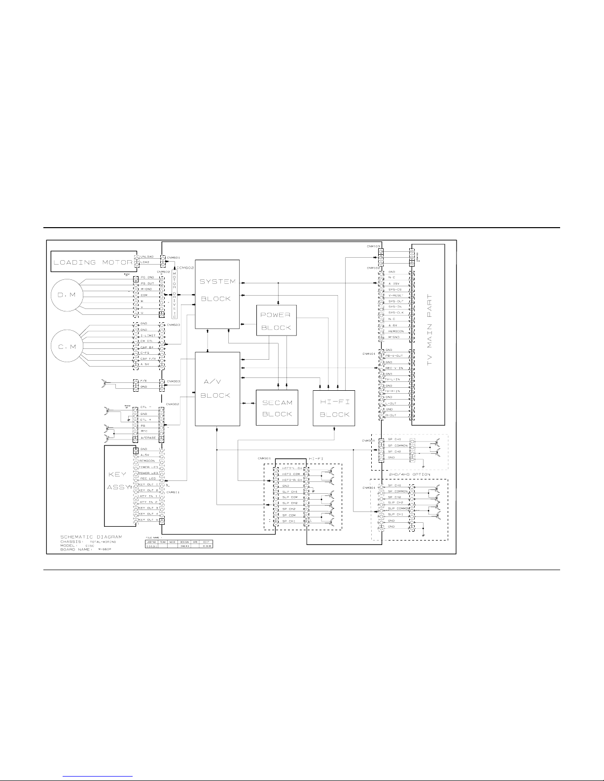
Wiring Diagram
Schematic Diagrams
1.
2.
3.
4.
5.
6.
7.
8.
9.
10.
11.
1. Precautions
1-1 Safety Precautions
1. Be sure that all of the built-in protective
devices are replaced. Restore any missing
protective shields.
2. When reinstalling the chassis and its
assemblies, be sure to restore all protective
devices, including: nonmetallic control knobs
and compartment covers.
3. Make sure that there are no cabinet openings
through which people—particularly
children—might insert fingers and contact
dangerous voltages. Such openings include
the spacing between the picture tube and the
cabinet mask, excessively wide cabinet
ventilation slots, and improperly fitted back
covers.
If the measured resistance is less than 1.0
megohm or greater than 5.2 megohms, an
abnormality exists that must be corrected
before the unit is returned to the customer.
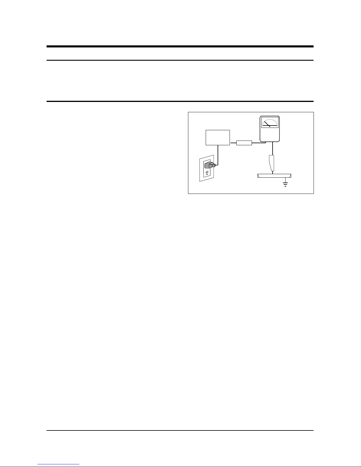
4. Leakage Current Hot Check (Figure 1-1):
Warning: Do not use an isolation
transformer during this test. Use a leakagecurrent tester or a metering system that
complies with American National Standards
Institute (ANIS C101.1, Leakage Current for
Appliances), and Underwriters Laboratories
(UL Publication UL1410, 59.7).
5. With the unit completely reassembled, plug
the AC line cord directly into the power
outlet. With the unit’s AC switch first in the
ON position and then OFF, measure the
current between a known earth ground (metal
water pipe, conduit, etc.) and all exposed
metal parts, including: antennas, handle
brackets, metal cabinets, screwheads and
control shafts. The current measured should
not exceed 0.5 milliamp. Reverse the powerplug prongs in the AC outlet and repeat the
test.
Fig. 1-1 AC Leakage Test
6. Antenna Cold Check:
With the unit’s AC plug disconnected from the
AC source, connect an electrical jumper across
the two AC prongs. Connect one lead of the
ohmmeter to an AC prong. Connect the other
lead to the coaxial connector.
7. X-ray Limits:
The picture tube is especially designed to prohibit X-ray emissions. To ensure continued
X-ray protection, replace the picture tube only
with one that is the same type as the original.
Carefully reinstall the picture tube shields and
mounting hardware; these also provide X-ray
protection.
8. High Voltage Limits:
High voltage must be measured each time servicing is done on the B+, horizontal deflection
or high voltage circuits. Correct operation of
the X-ray protection circuits must be
reconfirmed whenever they are serviced.
(X-ray protection circuits also may be called
“horizontal disable” or “hold-down”.)
Heed the high voltage limits. These include
the X–ray Protection Specifications Label, and
the Product Safety and X-ray Warning Note on
the service data schematic.
Precautions
Samsung Electronics 1-1
LEAKAGE
CURRENT
TESTER
DEVICE
UNDER
TEST
TEST ALL
EXPOSED METAL
SURFACES
3-WIRE CORD
ALSO TEST WITH
PLUG REVERSED
(USING AC ADAPTER
PLUG AS REQUIRED)
EARTH
GROUND
(READING SHOULD
NOT BE ABOVE
0.5mA)
Follow these safety, servicing and ESD precautions to prevent damage and protect against potential
hazards such as electrical shock and X-rays.

Samsung Electronics 2-1
2. Specifications
TELEVISION PART
Colour systems PAL(option) / SECAM(option) (UK;PAL)
TV standards L/L’(option), B/G(option), D/K(option) (UK;I)
Number of channels 100 programmes
Reception range/cable TV Hyperband/interband tuner
Aerial input 75 Ohms, coaxial cable
VCR PART
Format VHS standard
(PAL / SECAM(option) / MESECAM(option) / NTSC in playback only)
Heads Video: 2 rotary heads, LP(option), 4 Heads(option)
Audio/Control: 1 stationary head (linear)
Erase: 1 full track erase head
System Video Normal CCIR
System Audio Mono / NICAM&A2-STEREO
Luminance FM azimuth recording
Colour Down converted subcarrier phase shifted direct recording
FF/REW time Less than 100 seconds in FF with E-120
Wow and flutter (WTD) 0.4% maximum (SP)
Frequency response 100 Hz - 8 KHz
GENERAL
Power supply 220-240V~, 50Hz (110-260V~, 50/60Hz; option)
Consumption 14” (60W)
20”/21” (90W)
Audio output power 14” (1.5W)
20” (3W)
21” (1.5Watts x 2)
Number of loudspeakers 14”/20” (1)
21” (2)
Tube size 14” (37cm/34cmV)
20” (51cm/48cmV)
21” (55cm/51cmV)
Tube type BLACK MATRIX
Sockets 1 full RGB SCART on the rear
1 RCA input (audio and video) on the front
Earphones output (3.5 mm mini-jack)
1 aerial/cable TV coaxial input
Dimensions (W x D x H) 14” (368.5 x 388 x 381)
20” (488 x 477 x 488)
21” (520 x 495 x 508)
Weight 14” (11.7 kg)
20” (20.4 kg)
21” (23.2 kg)
Operating temperature 5°C - 40°C (41°F - 104°F)
Relative humidity 10% - 75%
The descriptions and characteristics given in this booklet are given for information purposes only and
are subject to modification without notice.
Disassembly and Reassembly
Samsung Electronics 3-1
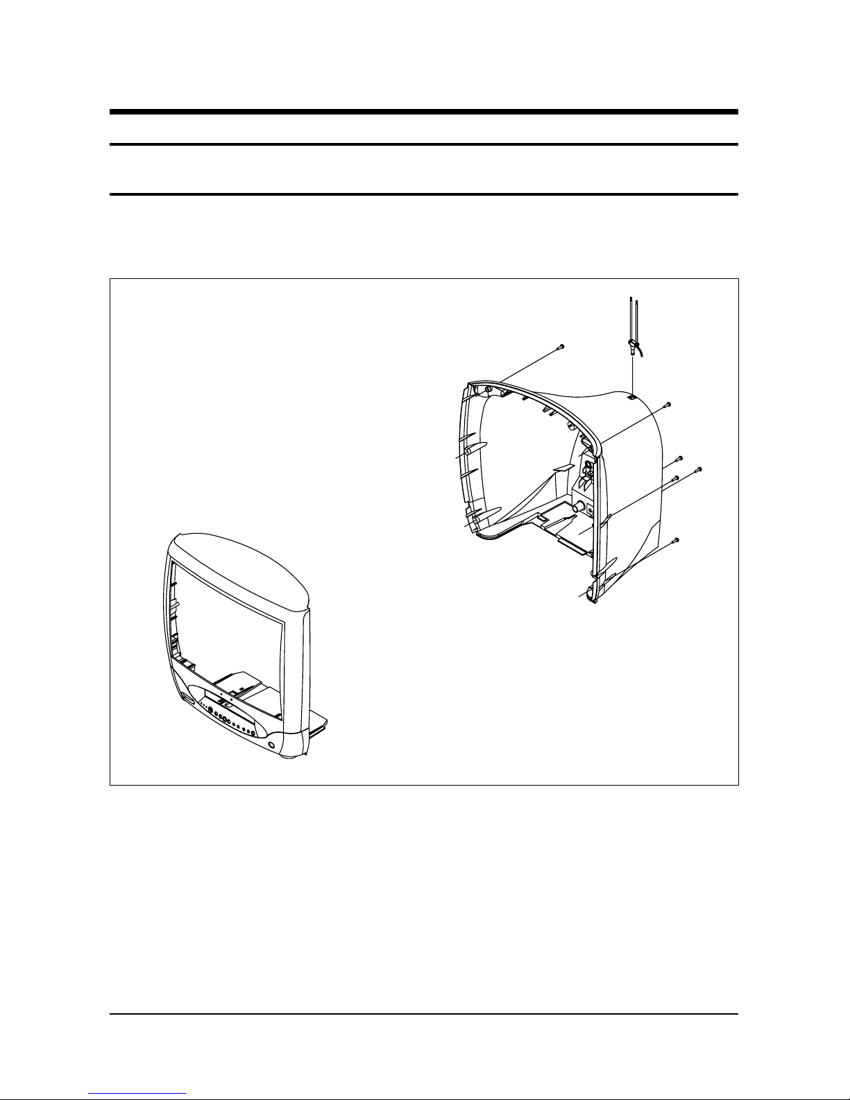
1. Remove the screws located on the side of the back cover.
3. Disassembly and Reassembly
3-1 Disassembly
3-1-1 Back Cover Removal
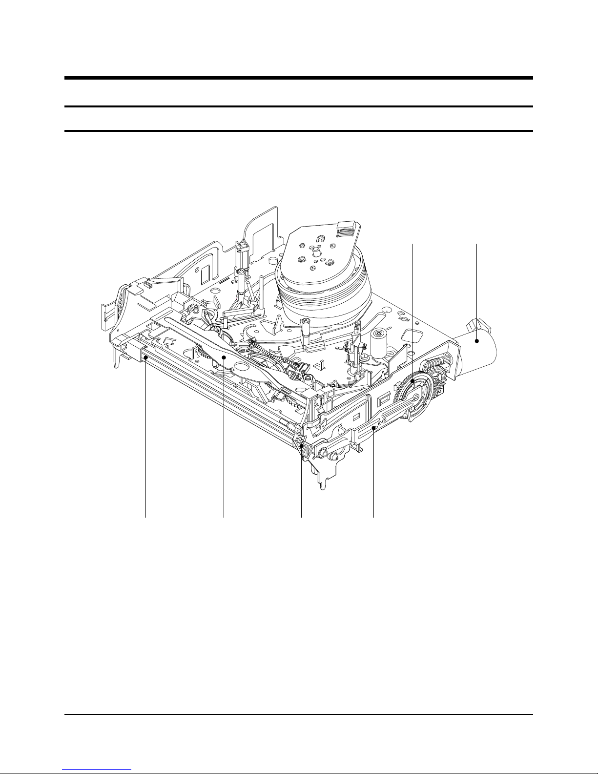
Samsung Electronics
4-1
Œ
´
ˇ
¨
ˆ
Ø
Fig. 4-1 Top parts Location-1
ΠGEAR FL CAM
´ MOTOR LOADING ASS’Y
ˇ LEVER FL ARM ASS’Y
¨ HOLDER FL CASSETTE ASS’Y
ˆ LEVER FL DOOR
Ø SLIDER FL DRIVE
4. Disassembly and Reassembly
4-1 Deck Parts Locations
4-1-1 Top View
Troubleshooting
Samsung Electronics 6-1
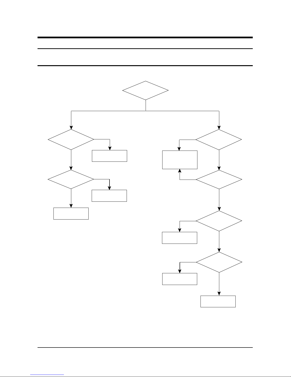
6. Troubleshooting
6-1 No Power (No Picture on)
Yes
Check
both terminal voltages
of C820 (125V)
Check both
terminal voltages of
C807 (280~300V).
Check D801~804
F801,Q801.
No
Is Q801 Pin 3
19~22V?
Check IC801
Check/Replace
T801.
No
Yes
No
Yes
Check
Voltage of 5V, 6V, 8V,
13V power line..
Check whether
each power line
is short or open.
No
No
Yes
Is IC901
Pin 64 Voltage 5V?
Check H.V SYNC on
IC901 Pins 1, 2
Check/Replace
IC901.
Check
IC901 Pin 3 is High
when power is On.
Check/Replace
IC902.
Check the voltage
of TU001.
Yes
Yes
No
No
Yes
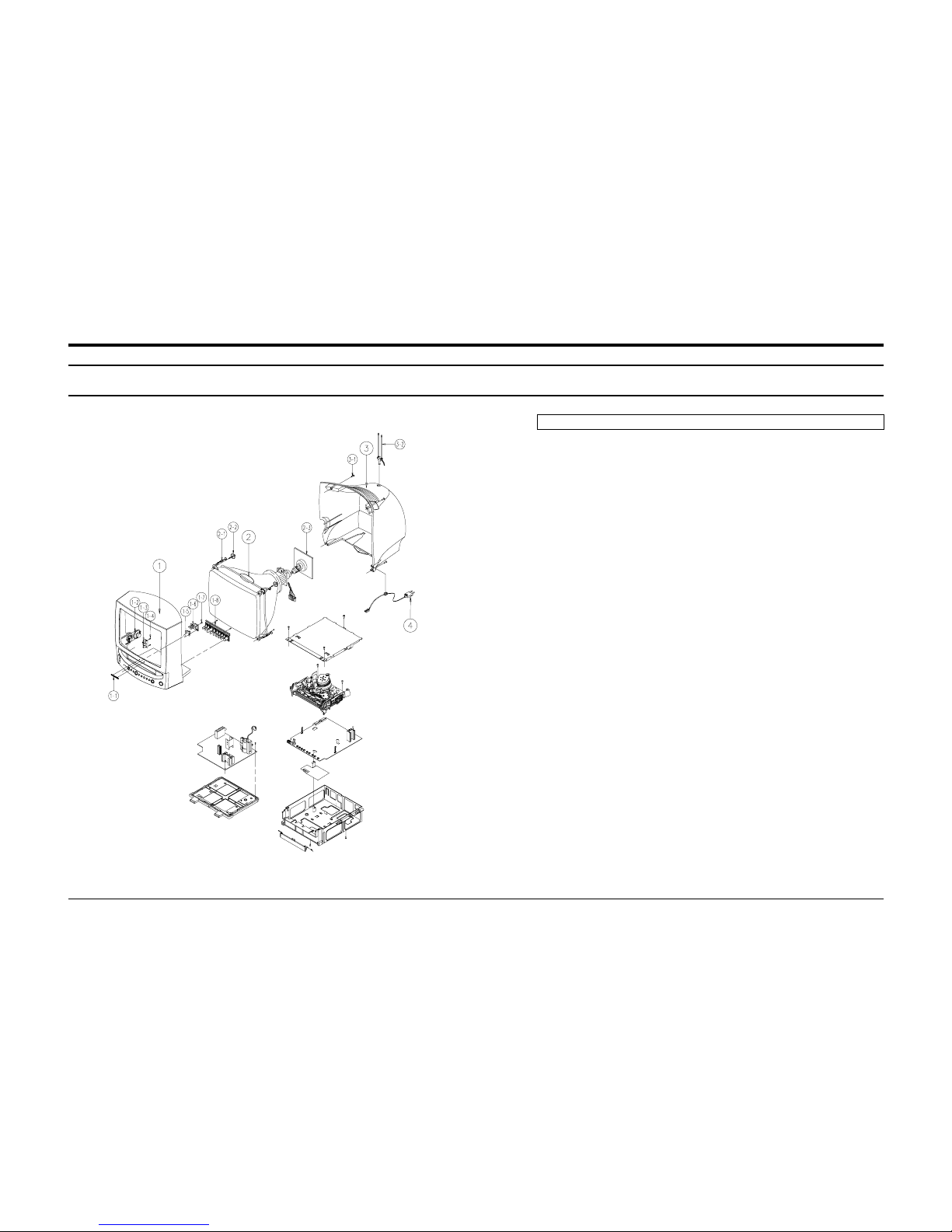
7. Exploded View & Parts List
7-1 TB14A53X/RAD
Exploded View & Parts List
Samsung Electronics 7-1
No Code No Description;Specification Q’ty Remark
1 AA91-00184D ASSY CABINET FRONT;-,14A5 MASTER,BK708P 1
AA64-31339P CABINET FRONT;14A5,C5,BK708P HITRON EL,H 1
1-1 AA64-70127F BADGE-BRAND;AL,SAMSUNG,SILVER,L40,R800,N 1
1-2 AA96-00149A ASSY-SPEAKER;-,-,16 OHM,2.5W,3001-001015 1
1-3 AA95-00630B ASSY-PCB,A/V;-,14/20/21,C15C,PAL,-,MO 1
1-4 6003-000333 SCREW-TAPTITE;RH,+,2S,M3,L10,ZPC(YEL),SW 2 AV+CF
1-5 AA64-00018A WINDOW-REMOCON;-,TVN-502V,-,PC,VIOLET,-, 1
1-6 AA64-00012A INDICATOR-LED;-,TVN-502V,-,PC,-,CLEAR,- 1
1-7 6003-000333 SCREW-TAPTITE;RH,+,2S,M3,L10,ZPC(YEL),SW 2 IND+CF
1-8 AA64-00051E PANEL CONTROL;14A5 MAST,HIPS,-,V0,BLK,-, 1
2 AA03-10002N CRT-COLOR;-,A34KQV42X,-300MG,14,90DEG,5 1
2-1 AA65-30016A CLAMP-D,COIL;-,NYLON-66,V0,-,NTR,DADH-36 2
2-2 AA60-10050R SCREW-ASSY;-,SWRCH18A,M5,L31.5,HH,+,WC,- 4 CRT
2-3 3704-000103 SOCKET-CRT;10P,22.5,14.3,SN,ISMS01S/BK 1
3 AA64-31340C CABINET-BACK;-,14A5,C5,SEA ,HIPS,V0,BLK 1
3-1 6002-000514 SCREW-TAPPING;RH,+,2,M4,L15,ZPC(BLK),SWR 4 CB+CF
3-2 AA42-00003A ANT ROD;-,3S,720mm,ABS,UL/CSA,- 1
4 AA96-20124A ASSY-POWER,CORD;-,EP2/YES(AU),H/C250,KJP 1

Electrical Parts List
Samsung Electronics 8-1
8-1 TB14A53X/RAD
ASSY PCB MAIN(OPT)
1 * AA94-02669C ASSY PCB MAIN(OPT);TB14A53X/RAD,C15C,NEW
..2 C237 2401-001840 C-AL;100uF,20%,16V,GP,TP,6.3x11,5
..2 C807 2401-002241 C-AL;220uF,+30-10%,400V,GP,ST,30x40
..2 CR402S 2301-001219 C-FILM,MPE-PPF;3.9nF,5%,1.6KV,TP,29x8.5x
..2 CR403S 2306-000188 C-FILM,MPPF;330nF,5%,400V,TP,26x19.5x11,
..2 GT02A AA39-20010B LEAD CONNECTOR-ASSY;,1P,YFH800-01,S,500,
..2 HC002 AA13-00087A IC HYBRID;-,TAR001,SIP,10P,-,BK
..2 IC301 AA96-50345E ASSY-H/S;-,VERT,AA62-30174A,TDA8356/N6A S.N.A
...3 AA62-30174A HEAT SINK-PS;-,SPC,T1.0,-,33X20X50,-,FT- S.N.A
...3 AA61-10162A BRACKET-IC;-,SBHG-1,T1.0,-,-,-,...3 6003-000334 SCREW-TAPTITE;RH,+,2S,M3,L6,ZPC(YEL),SWR S.N.A
...3 1204-001541 IC-VERTICAL DEF.;TDA8356/N6A,SIP,9P,-,PL
...3 0205-000129 GREASE-SILICON;SC102,JAPAN S.N.A
..2 IC601 1201-001386 IC-POWER AMP;7267,DIP,16P,-,DUAL,32dB,PL
..2 IC801S AA96-50298C ASSY-H/S;-,POWER,AA62-30171A,KA3S0680,C S.N.A
...3 AA63-30189A COVER-HEATSINK;-,-,AA62-30171,PC-ABS,V0,
...3 AA62-30171A HEAT SINK-ES;-,A6063 EXTR,-,-,-,WHT,40(3
...3 AA61-10386A BRACKET-IC;-,SECC 100,T1.0,-,-,-,KA2S068 S.N.A
...3 6003-000333 SCREW-TAPTITE;RH,+,2S,M3,L10,ZPC(YEL),SW S.N.A
...3 1203-001313 IC-PWM CONTROLLER;3S0680,TO-3P,5,150MIL,
...3 0205-000129 GREASE-SILICON;SC102,JAPAN S.N.A
..2 IC804 AA96-50407B ASSY H/S;-,VERTICAL,AA62-30154G,KA7806, S.N.A
...3 0205-000129 GREASE-SILICON;SC102,JAPAN S.N.A
...3 1203-000284 IC-POSI.FIXED REG.;7806,TO-220,3P,-,PLAS
...3 6003-000333 SCREW-TAPTITE;RH,+,2S,M3,L10,ZPC(YEL),SW S.N.A
...3 AA62-30154G HEAT SINK-ES;-,A6063 EXTR,-,WHT,50/16,-, S.N.A
..2 IC806 AA96-50153H ASSY-H/S;-,-,AA62-30013D,KA78R09,- S.N.A
...3 1203-001225 IC-POSI.FIXED REG.;78R09,TO-220,4P,-,PLA
...3 6003-000333 SCREW-TAPTITE;RH,+,2S,M3,L10,ZPC(YEL),SW S.N.A
...3 AA62-30013D HEAT SINK-ES;-,A6063 EXTR,-,-,55(21) T02 S.N.A
..2 IC903 1203-001752 IC-POSI.FIXED REG.;LF33CV,TO-220,3P,-,PL
..2 JS701 3722-000161 JACK-PIN;2P,3.4mm,SN,BLK,..2 L803 AA27-20003U COIL-DEGAUSSING;-,14,16.4ohm,75T,890mm,D
..2 LR401S AA27-30001K COIL-LINEARLITY;-,230uH,DR1215,PI0.5,14.
..2 LX801S AA29-30001C FILTER-LINE NOISE;-,39mH,1.0A,-,..2 T444S AA26-00004A TRANS-FLYBACK;-,FSA38026S,14INCH,125V
..2 T801S AA26-20007U TRANS-SWITCHING;-,90~260V,125V/16.5V/9.5
..2 TU01S AA40-10006MTUNER-F/S;TECC2949PG29A(S),PAL-B/G,TR,18
..2 AA99-30224S ASSY-PCB ROBOT; AA94-02669C ,ER S.N.A
...3 CN101 3711-003641 CONNECTOR-HEADER;BOX,12P,1R,2.5mm,STRAIG
...3 CN102 3711-003641 CONNECTOR-HEADER;BOX,12P,1R,2.5mm,STRAIG
...3 CX801S 2306-000318 C-FILM,MPPF;220nF,20%,250V,TP,-,22.5mm
...3 CX802S 2306-000318 C-FILM,MPPF;220nF,20%,250V,TP,-,22.5mm
...3 CY801S 2201-000987 C-CERAMIC,DISC;2.2nF,20%,400V,Y5U,TP,12.
...3 CY802S 2201-000987 C-CERAMIC,DISC;2.2nF,20%,400V,Y5U,TP,12.
...3 D818 AA96-00111C ASSY-H/S;-,-,AA62-30013L,FML-G12S,-
....4 0402-000233 DIODE-RECTIFIER;FML-G12S,200V,5A,-,-
....4 6003-000333 SCREW-TAPTITE;RH,+,2S,M3,L10,ZPC(YEL),SW S.N.A
....4 AA62-30013L HEATSINK-ES;-,-,-,-,44/22,-,WHT,-,-,-,- S.N.A
...3 D820 0402-000233 DIODE-RECTIFIER;FML-G12S,200V,5A,-,...3 FP801S 3601-000261 FUSE-CARTRIDGE;250V,3.15A,TIME-LAG,GLASS
...3 IC201S 1204-001440 IC-VIDEO SYSTEM;TDA8842,DIP,56P,300MIL,P
...3 IC701 0801-000961 IC-CMOS LOGIC;4053,MUTIPLEXER,DIP,16P,30
...3 IC702 0801-000213 IC-CMOS LOGIC;4052,MULTIPLEXER,DIP,16P,3
...3 IC901S AA09-00088A IC MICOM;SAA5543PS/M4-0258,C15C,52P,3.3
...3 IC902S 1103-000118 IC-EEPROM;24WC08,1Kx8Bit,DIP,8P,300MIL,1
...3 NT801S 1404-001045 THERMISTOR-NTC;4.7ohm,15%,2900K,35.0mW,T
...3 PC801S 0604-001038 PHOTO-COUPLER;TR,130-260%,200mW,DIP-4,ST
...3 PT801S 1404-000002 THERMISTOR-PTC;9ohm,20%,-,-,TR,RECT,...3 Q401 0502-001115 TR-POWER;KSC5386,NPN,50W,TO-3PF,ST,8...3 RL801S 3501-001040 RELAY-POWER;12VDC,500mW,10A,1FormA,15mS,
...3 SF101S 2904-001239 FILTER-SAW AV;38.9MHz,SIP5K,ST,16.3dB,B/
...3 T401 AA26-50001B TRANS-HORIZ.DRIVE;-,7.1mH,102uH,10-20uH,
...3 AA99-10218N ASSY-PCB MAIN,AUTO; AA99-30224S ,V S.N.A
....4 C101 2401-000030 C-AL;22uF,20%,25V,GP,TP,5x11,5
....4 C102 2202-000127 C-CERAMIC,MLC-AXIAL;10nF,+80-20%,25V,Y5V
....4 C107 2202-000807 C-CERAMIC,MLC-AXIAL;22nF,+80-20%,25V,Y5V
....4 C108 2401-000962 C-AL;22uF,20%,50V,GP,TP,5x11,5
....4 C109 2202-000632 C-CERAMIC,MLC-AXIAL;100nF,20%,50V,Z5U,TP
....4 C112 2305-000196 C-FILM,MPEF;150nF,5%,63V,TP,-,5mm
....4 C201 2401-002619 C-AL;47uF,20%,25V,GP,TP,5x11,5
....4 C202 2305-000412 C-FILM,MPEF;470nF,5%,63V,TP,-,5mm
....4 C204 2301-000224 C-FILM,PEF;22nF,5%,50V,TP,7.4x3.9x13mm,5
....4 C205 2401-000660 C-AL;2.2uF,20%,50V,GP,TP,5x11,5
....4 C206 2306-000122 C-FILM,MPPF;100nF,5%,50V,TP,7.3x4.0x5.0m
....4 C207 2401-001840 C-AL;100uF,20%,16V,GP,TP,6.3x11,5
....4 C208 2305-000412 C-FILM,MPEF;470nF,5%,63V,TP,-,5mm
....4 C209 2305-000289 C-FILM,MPEF;220nF,5%,63V,TP,-,5mm
....4 C210 2305-000412 C-FILM,MPEF;470nF,5%,63V,TP,-,5mm
....4 C211 2301-000232 C-FILM,PEF;3.3nF,5%,50V,TP,8.1x4.5x13mm,
....4 C212 2306-000122 C-FILM,MPPF;100nF,5%,50V,TP,7.3x4.0x5.0m
....4 C213 2306-000122 C-FILM,MPPF;100nF,5%,50V,TP,7.3x4.0x5.0m
....4 C214 2306-000122 C-FILM,MPPF;100nF,5%,50V,TP,7.3x4.0x5.0m
....4 C215 2401-000480 C-AL;10uF,20%,50V,GP,TP,5x11,5
....4 C219 2201-000273 C-CERAMIC,DISC;0.018nF,5%,50V,NP0,TP,5x3
....4 C221 2306-000122 C-FILM,MPPF;100nF,5%,50V,TP,7.3x4.0x5.0m
....4 C222 2401-001840 C-AL;100uF,20%,16V,GP,TP,6.3x11,5
....4 C225 2401-000603 C-AL;1uF,20%,50V,GP,TP,5x11,5
....4 C226 2401-000603 C-AL;1uF,20%,50V,GP,TP,5x11,5
....4 C227 2202-000796 C-CERAMIC,MLC-AXIAL;1NF,10%,50V,Y5P,TP,3
....4 C228 2309-000138 C-FILM,PE-PPF;100nF,5%,50V,TP,20x16x8.5,
....4 C230 2401-002144 C-AL;47uF,20%,16V,GP,TP,5x11,5
....4 C231 2401-000480 C-AL;10uF,20%,50V,GP,TP,5x11,5
....4 C232 2202-000849 C-CERAMIC,MLC-AXIAL;18pF,5%,50V,CH,TP,3.
....4 C233 2202-000243 C-CERAMIC,MLC-AXIAL;33pF,5%,50V,SL,TP,3.
....4 C234 2301-000445 C-FILM,PEF;4.7nF,5%,50V,TP,5.5x7x3mm,5mm
....4 C236 2301-000232 C-FILM,PEF;3.3nF,5%,50V,TP,8.1x4.5x13mm,
....4 C238 2301-000383 C-FILM,PEF;10nF,5%,50V,TP,6x7x3.2mm,5mm
....4 C239 2401-000603 C-AL;1uF,20%,50V,GP,TP,5x11,5
....4 C249 2401-000480 C-AL;10uF,20%,50V,GP,TP,5x11,5
....4 C250 2306-000122 C-FILM,MPPF;100nF,5%,50V,TP,7.3x4.0x5.0m
....4 C251 2306-000122 C-FILM,MPPF;100nF,5%,50V,TP,7.3x4.0x5.0m
....4 C253 2202-000210 C-CERAMIC,MLC-AXIAL;270PF,10%,50V,Y5P,TP
....4 C254 2202-000127 C-CERAMIC,MLC-AXIAL;10nF,+80-20%,25V,Y5V
....4 C255 2401-002619 C-AL;47uF,20%,25V,GP,TP,5x11,5
....4 C257 2202-000791 C-CERAMIC,MLC-AXIAL;150pF,10%,50V,Y5P,TP
....4 C260 2202-000121 C-CERAMIC,MLC-AXIAL;100pF,10%,50V,Y5P,TP
....4 C261 2301-000192 C-FILM,PEF;1nF,5%,50V,TP,5.3x10mm,5mm
....4 C262 2202-000210 C-CERAMIC,MLC-AXIAL;270PF,10%,50V,Y5P,TP
....4 C265 2401-002144 C-AL;47uF,20%,16V,GP,TP,5x11,5
....4 C301 2202-000796 C-CERAMIC,MLC-AXIAL;1NF,10%,50V,Y5P,TP,3
....4 C302 2401-002293 C-AL;68uF,20%,100V,WT,TP,10x20,5
....4 C303 2305-000149 C-FILM,MPEF;100nF,5%,100V,TP,12x12.5x6.5
....4 C304 2305-000285 C-FILM,MPEF;220NF,5%,100V,TP,10.5X5.5X15
....4 C305 2202-000796 C-CERAMIC,MLC-AXIAL;1NF,10%,50V,Y5P,TP,3
....4 C306 2401-002288 C-AL;470uF,20%,25V,WT,TP,10x20,5
....4 C307 2305-000285 C-FILM,MPEF;220NF,5%,100V,TP,10.5X5.5X15
....4 C308 2305-000407 C-FILM,MPEF;470nF,5%,100V,TP,-,5mm
....4 C401 2301-000383 C-FILM,PEF;10nF,5%,50V,TP,6x7x3.2mm,5mm
....4 C405 2305-000704 C-FILM,MPEF;100nF,5%,250V,TP,16.5x10.3x5
....4 C406 2201-000556 C-CERAMIC,DISC;0.47nF,10%,500V,Y5P,TP,5.
....4 C407 2401-002288 C-AL;470uF,20%,25V,WT,TP,10x20,5
....4 C408 2201-000556 C-CERAMIC,DISC;0.47nF,10%,500V,Y5P,TP,5.
....4 C409 2401-001661 C-AL;68uF,20%,100V,GP,TP,10x16,5
....4 C411 2201-000556 C-CERAMIC,DISC;0.47nF,10%,500V,Y5P,TP,5.
....4 C412 2401-000927 C-AL;22uF,20%,250V,GP,TP,13x20,5
....4 C413 2401-003028 C-AL;100uF,20%,25V,WT,TP,6.3x11,5
....4 C414 2201-000639 C-CERAMIC,DISC;0.68nF,10%,2kV,Y5P,TP,9x5
....4 C415 2305-000382 C-FILM,MPEF;4.7nF,5%,400V,TP,-,5mm
....4 C601 2401-001998 C-AL;1000uF,20%,25V,GP,TP,10x20,5mm
....4 C602 2305-000665 C-FILM,MPEF;100nF,5%,63V,TP,7.5x4.0x5.0m
....4 C604 2401-002619 C-AL;47uF,20%,25V,GP,TP,5x11,5
Loc. No. Code No. Description ; Specification Remark Loc. No. Code No. Description ; Specification Remark
8. Electrical Parts List
!!!!!
!
!
!!!!!
!!!
!
!
!!!
!

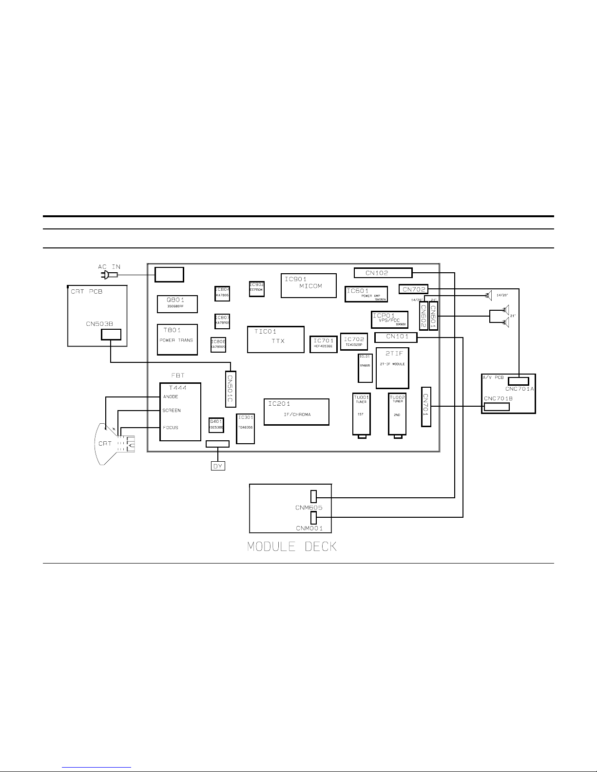
9. Block Diagrams
9-1 C15C Video Block Diagram
Block Diagrams
Samsung Electronics 9-1
9-1-1 Notes
The TV’s 1st and 2nd tuners (and VCR module) are “multi-system.” compatible:
IC201 (TDA8842/8841) is the video, chroma, and deflection (VCD) IC .
9-1-1(A) TAPE PLAYBACK (REGARDLESS OF ORIGINAL RECORDING SYSTEM)
If the output PB signal of micom pin 6 is high, the PB signal outputs from module deck 2, passes
through IC 702 pins 2 and 3 and out to another VCR . The output signal of IC701 pin 1 (pin 15)
outputs from IC201S pin 17 .
9-1-1(B) VIEWING NORMAL CHANNEL WHILE RECORDING A SCRAMBLED CHANNEL:
The output CVBS (Composite Video Signal) of the 2nd IF outputs to IC702pin 3 when the micom’s pin 7
V/T/H (VCR tuner high) is high . The decoded signal goes to IC701 pin 2, where it is fed to IC 701 pin
4 (high output of micom’s’ pin 8— AV/Tuner), and out to VCR pin 4 (module deck) for recording.
9-1-1(C) VIEWING A SCRAMBLED CHANNEL WHILE RECORDING AN UNSCRAMBLED CHANNEL.
The output CVBS of the 2nd IF is fed from IC701 pin 5 to IC701 pin 4 (low output of micom
pin 8—AV/tuner). Then it goes to the module deck pin 4 for recording.
The scrambled signal (CVBS) is fed to IC702 pin 1 through the 1st IF, and then to IC702 pin 3 (micom’s
pin 7, V/T/H registers low). Then it goes to the decoder input. The descrambled signal goes to IC701
pins 2 and 15 (PH high output of micom’s pin 6), and then to IC201S pin 17, where it outputs as RGB.
9-1-1(D) SYNCHRONOUS RECORDING:
The viewer sees the signal from the 1st tuner , while the signal from the second tuner is recorded.
Audio processing for the French system type is shown in the table.
10. Wiring Diagram
10-1 C15C Wiring Diagram
Wiring Diagram
Samsung Electronics 10-1
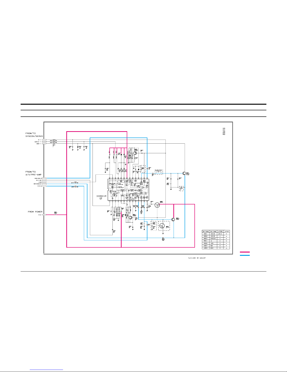
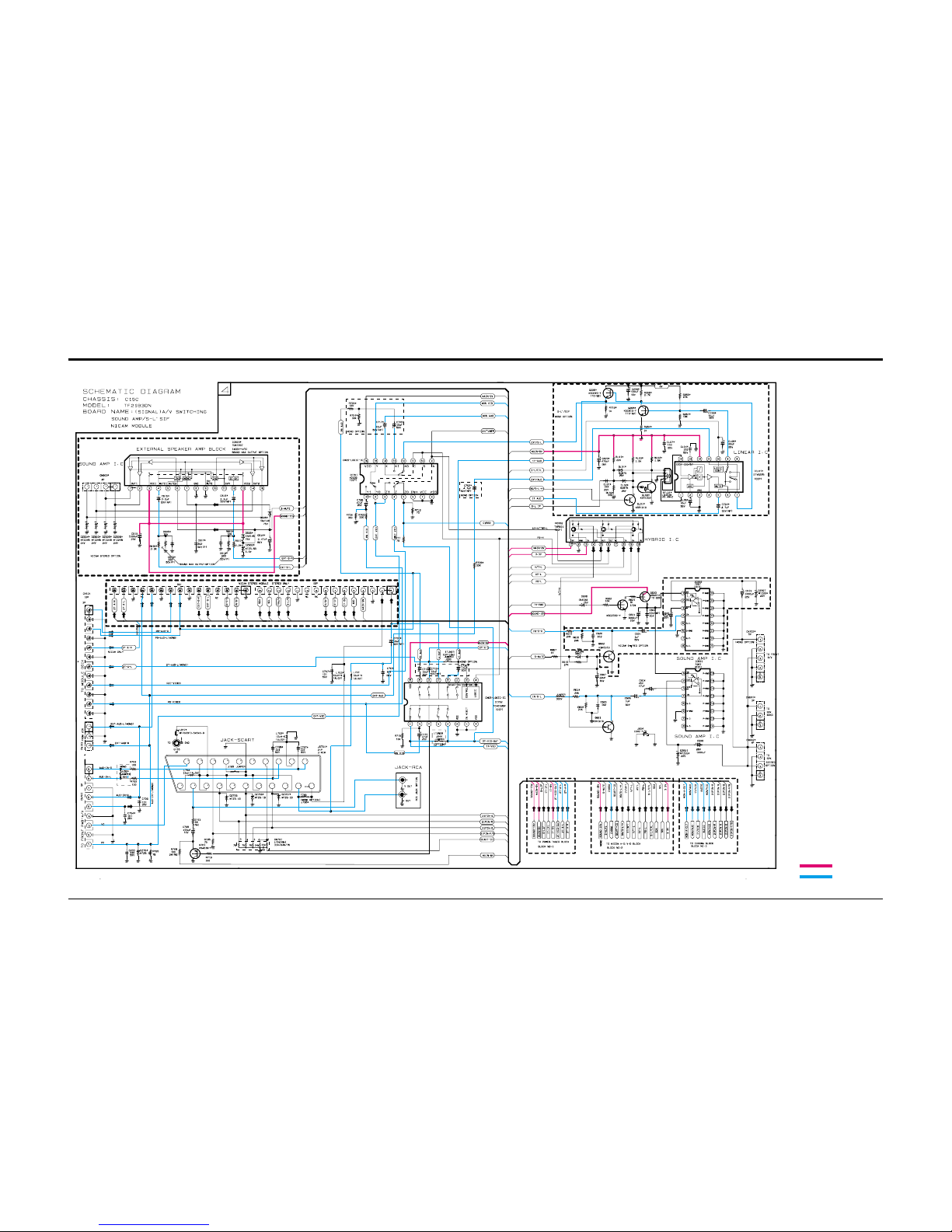
Schematic Diagrams
11-1Samsung Electronics
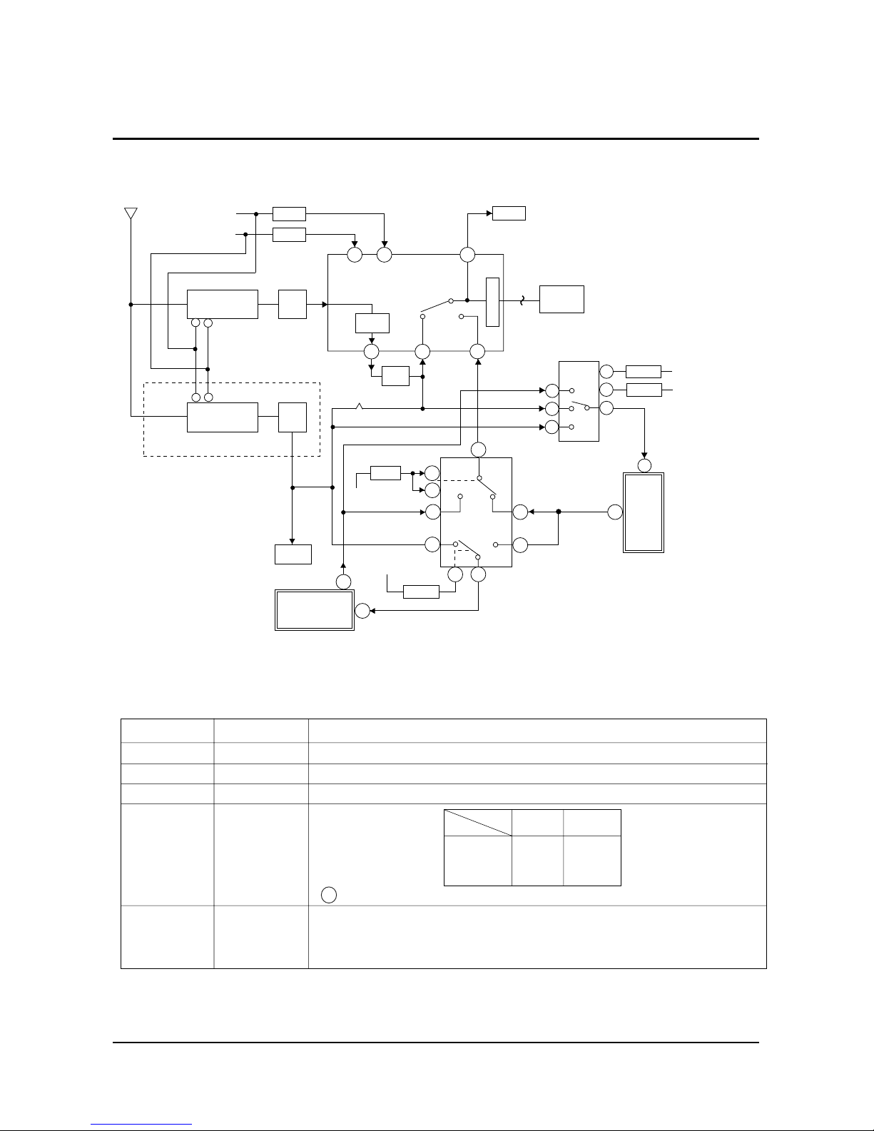
11. Schematic Diagrams
11-1 VCR (SECAM BLOCK)
: Power Line
: Signal Line
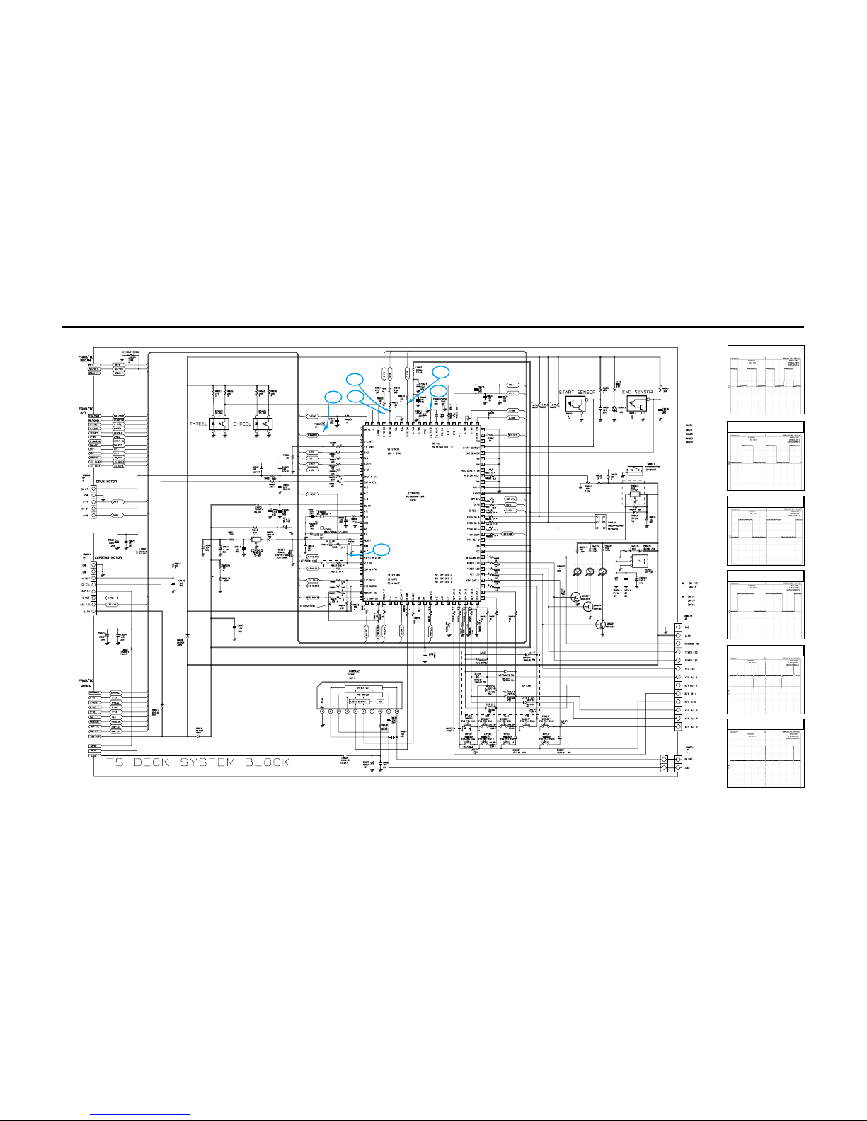
Schematic Diagrams
11-2 Samsung Electronics
11-2 VCR (SYSTEM BLOCK)
TP4
TP2
TP6
TP5
TP1
TP3
TP1
TP2
TP3
TP4
TP5
TP6
TP1
TP2
TP3
TP5
TP4
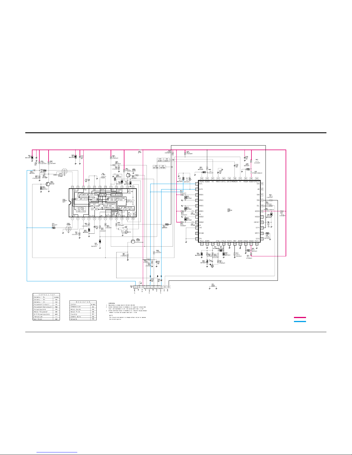
Schematic Diagrams
11-3Samsung Electronics
11-3 VCR (A/V BLOCK)
TP1
TP2
TP3
TP4
TP5
Schematic Diagrams
11-4 Samsung Electronics
11-4 VCR (POWER BLOCK)
: Power Line
: Signal Line
Schematic Diagrams
11-5Samsung Electronics
11-5 TV MAIN (1/4)
: Power Line
: Signal Line
TP1
TP2
TP3
TP4
TP5
Schematic Diagrams
11-6 Samsung Electronics
11-6 TV MAIN (2/4)
TP2
TP1
TP3
TP6
TP4
TP5
: Power Line
: Signal Line
TP1
TP2
TP3
TP4
TP5
TP6

Schematic Diagrams
11-7Samsung Electronics
11-7 TV MAIN (3/4)
TP1
TP2
TP3
TP4
TP5
TP6
TP12
TP11
TP 8
TP 7
: Power Line
: Signal Line
Schematic Diagrams
11-8 Samsung Electronics
11-8 TV MAIN (4/4)
: Power Line
: Signal Line
Schematic Diagrams
11-9Samsung Electronics
11-9 TUNER-IF NICAM(STEREO)
: Power Line
: Signal Line
Schematic Diagrams
11-10 Samsung Electronics
11-10 2’nd IF(STEREO)
: Power Line
: Signal Line
Schematic Diagrams
11-11Samsung Electronics
11-13 2'nd IF PAL/SECAM-B/G, D/K, I OPTION (MONO)11-11 IF (MONO) 11-12 CRT
TP1
TP2
TP3
TP3TP2TP1
: Power Line
: Signal Line
Schematic Diagrams
11-12 Samsung Electronics
11-16 FRONT-A/V(MONO)
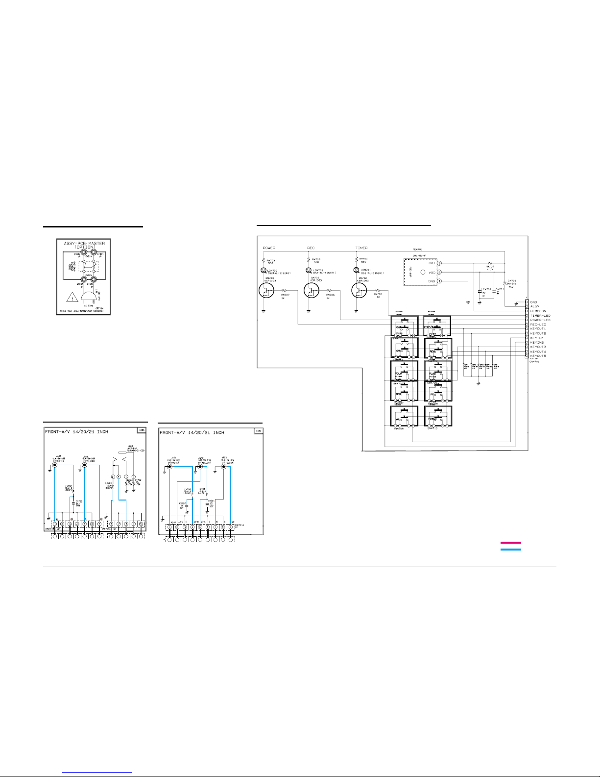
11-14 MASTER
11-15 CONTROL
11-17 FRONT-A/V (STEREO)
: Power Line
: Signal Line
Schematic Diagrams
11-13Samsung Electronics
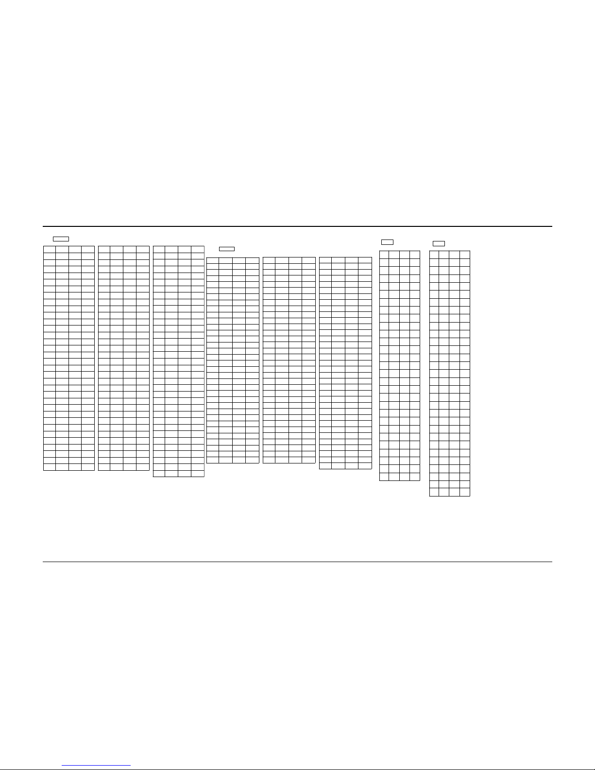
11-18 Voltages (VTR)
PLAY REC STOP
1 2.5 2.5 2.5
2 2.5 2.5 2.5
3 2.5 2.5 2.5
4 2.5 2.5 2.5
5 2.5 2.5 0
6 2.5 2.5 2.5
7 2.5 2.5 2.5
8 0 0 0
9 0 0 0
10 1.6 1.6 2
11 3.2 3.2 3.2
12 5 2 2.5
13 1.5 1.5 2
14 1.5 1.5 1.6
15 2.2 2.2 2.2
16 5 5 5
17 3 0 0
18 1.8 2.1 2.2
19 2.1 2.1 2.2
20 2.8 2.8 3.2
21 2.1 2.1 2.5
22 0 0 0
23 5 5 5
24 5 5 5
25 1.8 1.8 2.8
26 0.8 0 1
27 4.1 4.1 4.1
28 4.1 4.1 4.1
29 0.8 0.8 3
30 1 0 1
31 2.1 2.1 3.5
32 1.8 1.8 2
33 2 2 1.5
PLAY REC STOP
34 1.8 1.8 1.8
35 3.5 3.5 3.5
36 1.8 1.8 2
37 4.9 4.9 5
38 1.8 1.8 1.8
39 4 4 4
40 5 5 5
41 2.7 2.7 3
42 3 3 3.2
43 1.9 1.9 2
44 4.3 4.3 0
45 1.8 1.8 2
46 1.5 1.4 1.5
47 2 2 9
48 2.3 2.3 2.2
49 1.2 1.2 1
50 0 0 0
51 1.9 1.9 0
52 2.4 2.4 2.5
53 0 0 0
54 2.4 2.4 2.5
55 5 5 5
56 3.5 3.5 0
57 3.4 3.4 3.5
58 5 5 5
59 3.4 3.4 3.5
60 3.5 3.5 3.5
61 3.3 3.3 3.5
62 3.5 3.5 3.5
63 4 4 0
64 2.2 2.2 0
65 2.4 2.4 2.2
66 2.5 2.5 3
PLAY REC STOP
67 4 4 4
68 0 0 0
69 0.7 0.7 0.7
70 2 2 2
71 2.5 2.5 2.5
72 0.3 2.5 3
73 2.5 2.5 3.5
74 2 0 2
75 5 5 5
76 2.5 2.5 2.5
77 0 0 0
78 2.5 2.5 0
79 2.5 2.5 2.5
80 2.5 5 2.5
81 0 0 0
82 1.8 4.1 1
83 0 0 0
84 1.8 4.1 1
85 1.8 4.1 1
86 0 0 0
87 5 5 5
88 1.8 4.1 2
89 0 0 0
90 1.8 4.1 2
91 1.8 4.1 2
92 4 1.6 0
93 4 4.0 0
94 0.5 0.7 0
95 0 0 0
96 2.5 2.5 2.5
97 0 0 0
98 2.5 2.5 2.5
99 5 4.3 5
100 2.5 2.5 2.5
ICM301
PLAY REC STOP
1 5 5 5
2 0 0 0
3 5 5 5
4 5 5 5
5 5 5 5
6 5 5 5
7 5 5 5
8 5 5 5
9 5 5 0
10 5 5 0
11 0 0 0
12 0 0 0
13 0 0 0
14 5 5 5
15 3.5 3.5 3.5
16 4.5 4.5 4.5
17 0 0 0
18 4.5 4.5 4.5
19 3.5 3.5 3.5
20 5 5 5
21 0 0 0
22 0 0 0
23 5 5 0
24 5 5 0
25 5 5 0
26 0 0 0
27 5 5 5
28 5 5 5
29 5 5 0
30 0 0 0
31 0 0 0
32 5 5 5
33 0 0 0
PLAY REC STOP
34 0 0 0
35 0 0 0
36 0 0 0
37 0 0 0
38 5 5 5
39 5 5 5
40 0 0 0
41 5 5 5
42 5 5 5
43 5 5 5
44 5 5 5
45 0 0 0
46 0 0 0
47 0 0 0
48 5 5 5
49 5 5 5
50 5 5 5
51 5 5 5
52 5 5 5
53 5 5 5
54 5 5 5
55 0 5 0
56 0 0 0
57 0 0 0
58 5 5 5
59 5 5 5
60 5 5 5
61 5 5 5
62 0 0 0
63 0 0 0
64 5 5 5
65 0 0 0
66 0 5 0
PLAY REC STOP
67 5 0 0
68 0 0 0
69 5 5 5
70 5 5 5
71 0 0 0
72 1.8 1.8 1.8
73 0 0 0
74 0 0 0
75 0 0 0
76 0.7 0.7 0.7
77 0.7 0.7 0.7
78 0 0 0
79 0 0 0
80 0 0 0
81 3 0 0
82 4 0 0
83 0 0 0
84 0 0 0
85 2.5 5 2.5
86 2.5 5 2.5
87 2.5 2.5 2.5
88 2.5 2.5 2.5
89 2.5 2.5 2.5
90 2.5 2.5 2.5
91 0 0 0
92 5 5 5
93 5 5 5
94 0 5 0
95 0 0 0
96 5 5 5
97 5 5 5
98 5 5 0
99 5 5 0
100 5 5 5
ICM601
PLAY REC STOP
1 4 0.8 0.8
2 2 2 2
3 4 4 4
4 3.5 3.5 3.5
5 0 0 0
6 0 0 0
7 0 0 0
8 2.5 2.5 2.5
9 2.5 2.5 2.5
10 2.5 2.5 2.5
11 2.5 2.5 2.5
12 4.5 4.5 4.5
13 2.5 2.5 2.5
14 2.5 4.7 4.5
15 3 2.5 2.5
16 5 1 1
17 2.5 2.5 2.5
18 2 2 2
19 2.5 2.5 2.5
20 2.5 2.5 2.5
21 2.5 2.5 2.5
22 5 5 5
23 3 3 3
24 3 3 3
25 4.1 3 3
26 5 0 0
27 4.1 4.1 4.1
28 3.1 3.1 3.1
PLAY REC STOP
1 0.9 0.9 0
2 2.6 2.6 0
3 5.2 5.2 5.2
4 2.6 2.6 2.6
5 2.6 2.6 2.6
6 2.6 2.6 2.6
7 5 5 0
8 5 5 0
9
12.5 12.5
13
1000 0
11 5 5 5.1
12 5 5 5.1
13 0 0
0
14 0 0 0
15 0 0
0
16 8.4 8.8 0
17 8.4 8.8
0
18 8.4 8.8 0
19 5.2 5.2 0
20 0 0 0
21 12.5 12.5 13
22
8.4 8.2
0
23
8.4
8.2 0
24 8.4 8.2 0
25 1.8 1.8 2.6
26
1.8 1.8
0
27
1.4
1.4 1
28
27
28
2.4
5.2
0
2.5
2
5.2 0
00
ICM901
ICM602
Schematic Diagrams
11-14 Samsung Electronics
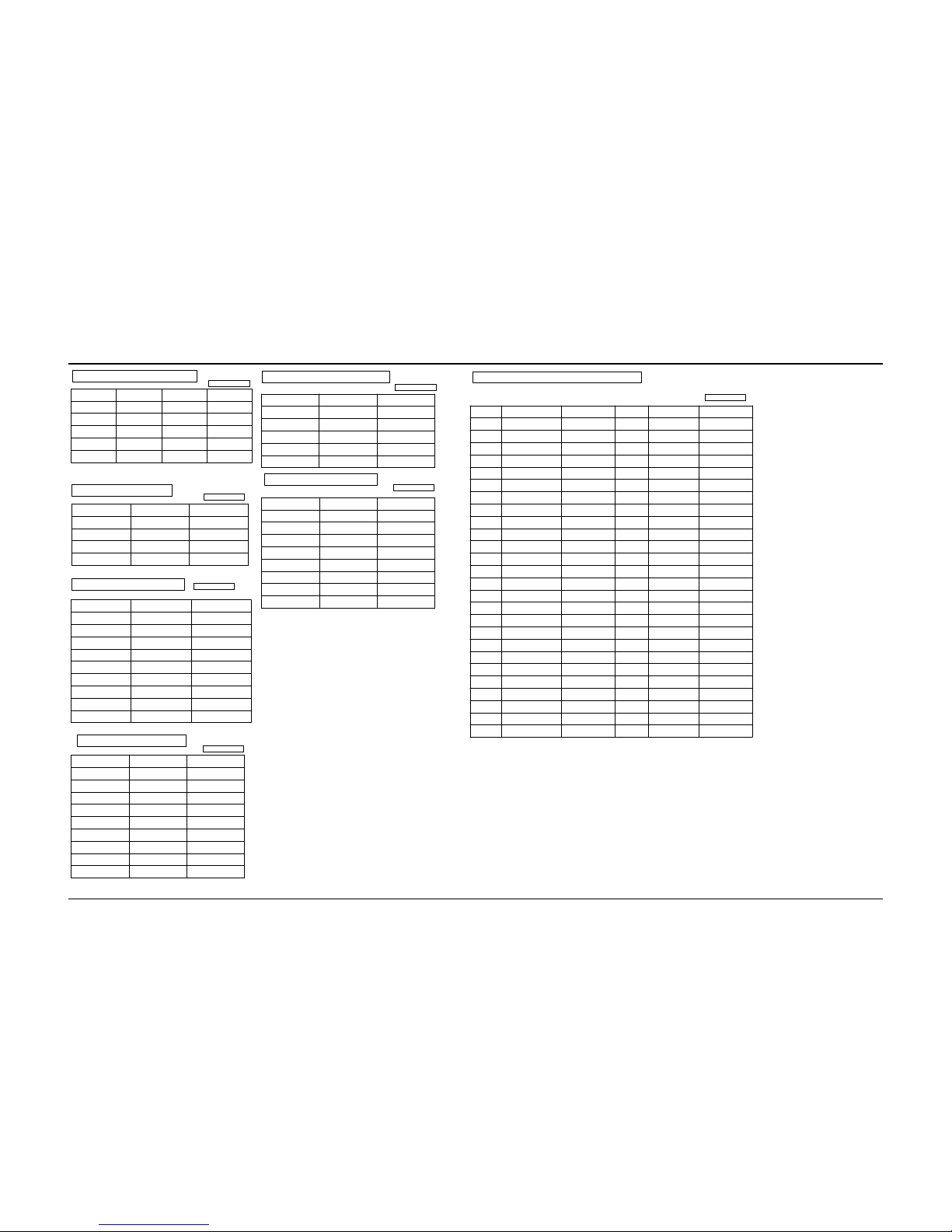
11-19 Voltages (TV)
IC901 : SAA5554PS-OTP
Units : Volts
PIN NO PIN NAME VOL TAGES(V) PIN NO PIN NAME VO L TAGES(V)
1
0.67
0.67
37
N.C
-
-
-
2
-
38
GND
3
5.2
39
GND
4 - 40
S-MUTE
2.8
5
ST BY-REC
-
-
-
-
-
41
VDD
3.2
6
PB-L
AV-L
VT-L
HOLD
1T/AFT
2T/AGC
2T/AFT
SCART-ID
GND
42
OSD B
-
-
-
-
7 43
BUS-STOP
8 44
OSD R
9 3.2
3.2
2.48
45
F/B
10 2.7 46
H-SYNC
0.79
11
D-coil
47
V-SYNC
-
12 48
VSSP
-
13 49
VDD
3.2
3.2
14
BG/I
50
GND
-
15 D/K 51
Xtal
1.6
1.6
16
1TS-L H
5.2 52
Extal
17
S-L H
53
RESET
-
18 FRA-H 3.7
4.9
54
VDD
19 LNA 4.4 55
REMOCON
5.2
5.1
20 TV PWR 3.2 56
TV CLK
21 PB MUTE 57
V-SYNC INTER
-
22 VSSA -
58
TV SI
-
23
CVBS0
0.2 59
TV SO
1.0
24 CVBS1 1.3 60
S-L CTL
-
25 BLACK
0.48
61~62 SCL
TV CS
2.3
26
IREF
1.3 63~64
SDA
2.2
OSD G
Q801 : KA3S0680RF
PIN NO PIN NAME STAND-BY POWER ON
1 DAR.IN 299 290
2 GND - 3 VCC 19.5 20.3
4 VFB 0.2 1.3
5 SYNC 0.8 6.7
Units : Volts
IC801 : PC123Y
Units : Volts
PIN NO STAND-BY POWER
1 16.5 16.7
2 15.4 15.7
3 GND GND
4 0.2 1.3
IC501 : TDA6107Q
Units : Volts
PIN NO PI N NAME VO L TAGES(V)
1 B-IN 2.4
2 R-IN 2.4
3 G-IN 2.5
4 GND 5 lom 5.4
6 Vdd 166
7 G-OUT 90~115
8 R-OUT 93~118
9 B-OUT 97~119
IC902 : 24C08,24C04,24C16
Units : Volts
PIN NO PIN NAME VOLT AGES(V)
1~4 GND -
5 SDA 4.8
6 SCL 4.8
7 GND 8 VDD 5.2
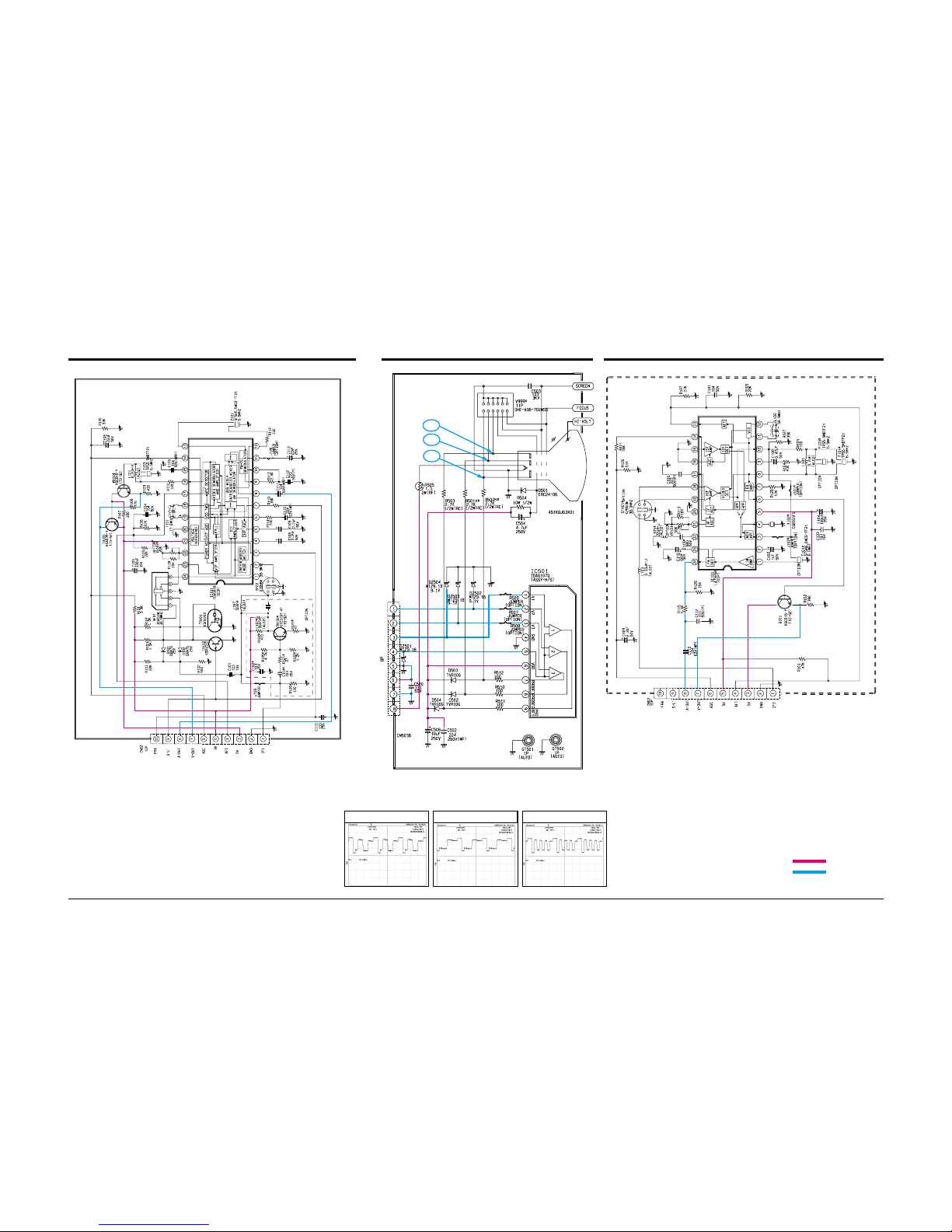
IC301 : TDA8356
Units : Volts
PIN NO PIN NAME VOLT AGES(V)
1 VD-INPUT 2.2
2 VD+INPUT 2.2
3 VCC 16.9
4 OUTPUT 8.2
5 GND 6 VFB 41.5
7 OUT 8.5
8 VO 9 VI 8.2
IC601 : TDA7267A
Units : Volts
PIN NO PIN NAME VOLT AGES(V)
1 VS 1.6
2 OUT 8.5
3 SVR 8.7
4 IN 0.8
5 N.C 6 S-GND -
7~8 N.C -
9~16 P-GND -
Schematic Diagrams
11-15Samsung Electronics
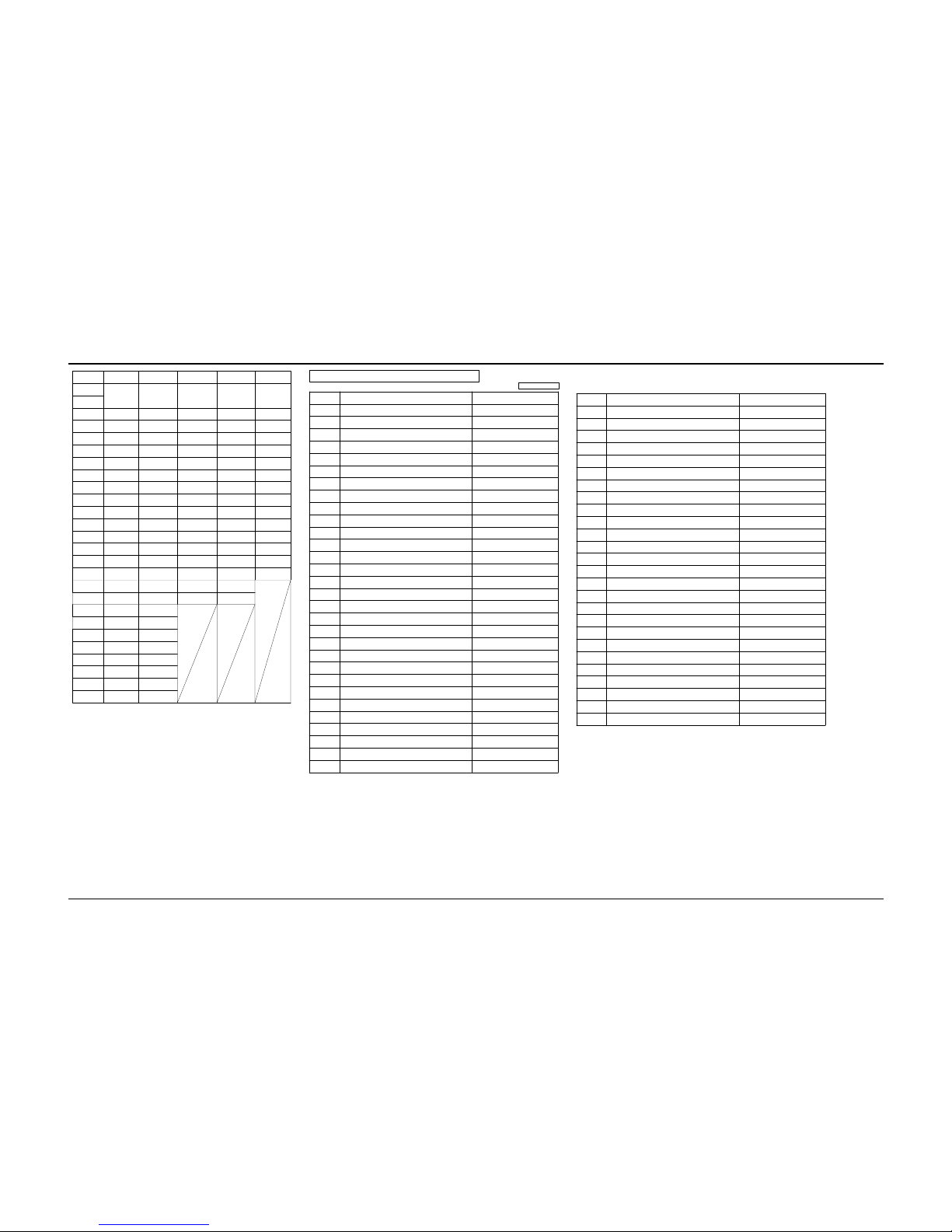
11-20 Voltages (TV)
LOC I C101* IC101* IC 701 IV 702 I CL01*
IC
TDA9818
2T-IF(F)
LA7565B
2T-IF(W)
TC4053BP TC4052BP STV8225
PIN NO
1 3.3 2.0 - 1.6 4.2
2 3.3 2.2 - 0.5 3.2
3 - 7.4 - 1.6 4 2.0 8.0 1.1 - 0.6
5 2.1 8.9 1.1 2.2 4.3
6 3.9 3.8 - - 3.5
7 1.7 3.2 - - 4.3
8 2.4 2.7 - - 6.3
9 2.3 3.7 0.8 0.8 4.3
10 2.3 2.7 0.8 0.8 3.5
11 1.6 8.3 0.8 - 4.3
12 2.0 8.3 2.2 4.0 9.0
13 2.7 0.3 - 3.4 4.3
14 4.2 7.9 2.1 2.2 4.3
15 1.4 - - 0.4
16 1.9 - 8.9 8.9
17 0.4 2.9
18 2.6 3.4
19 2.6 3.4
20 - 21 4.9 1.7
22 0.8 2.4
23 3.2 3.3
24 3.2 3.3
IC201 : TDA8842/8841
Units : Volts
PIN NO PIN NAME VOLTAGES(V)
1 SOUND IF INPUT 2 EXT.AUDIO INPUT 3.6
3 N.C 4 N.C 5 PLL LOOPFILTER 2.4
6 IF VIDEO OUTPUT 3.2
7 SCL 4.8
8 SDA 4.8
9 BANDGAP DECOUPLING 6.6
10 CHROMA INPUT 11 Y/CVBS INPUT 3.3
12 MAIN POSITIVE SUPPLY 8.0
13 INT.CVBS INPUT 3.9
14 GND 15 AUDIO OUT 3.0
16 SECAM DECOUPLING 17 EXT.CVBS INPUT 3.3
18 BLACK CURRENT INPUT 5.0
19 BLUE OUTPUT 3.0
20 GREEN OUTPUT 3.2
21 RED OUTPUT 3.2
22 V-GUARD INP / BEAM CUR.LIMITTER 2.0
23 RED INPUT 3.4
24 GREEN INTPUT 3.4
25 BLUE INTPUT 3.4
26 RGB INSERTION SWITCH INP 0.1
27 LUMINANCE INPUT 2.6
28 LUMINANCE OUTPUT 2.6
29 B-Y OUTPUT 30 R-Y OUTPUT -
PIN NO PIN NAME VOLT AGES(V)
31 B-Y OUTPUT 32 R-Y OUTPUT 33 SUBCARRIER OUTPUT 34 X-TAL(3.58) 2.4
35 X-TAL(4.43/3.58) 2.4
36 LOOPFILTER BURST PHASE DET 4.9
37 POSITIVE SUPPLY 8.0
38 CVBS OUTPUT 2.7
39 DECDIG 4.9
40 HOR OUTPUT 0.3
41 SANDCASTLE OUTP/FLY-BACK INP 0.5
42 PHI2 FILTER / FLASHPROT 3.2
43 PHI1 FILTER 3.9
44 GND 45 EAST-WEST DRIVE/AVL OUTPUT 46 VERT.DRIVE POS 2.2
47 VERT.DRIVE NEG 2.2
48 IF INPUT 4.5
49 IF INPUT 4.5
50 EHT/OVERVOLTAGE PROTECTION INP 2.1
51 VERT.SAWTOOTH CAPACITOR 3.7
52 REFERENCE CURRENT INPUT 3.8
53 AGC DECOUPLING CAPACITOR 4.2
54 TUNER AGC INPUT 4.4
55 AUDIO DEEMPHASSIS 2.8
56 DECOUPLING SOUND DEMODULATOR 2.4
Wiring Diagram
10-2 Samsung Electronics
10-2 C15C Wiring Diagram
Block Diagrams
9-2 Samsung Electronics
9-2 C15C Video Block Diagram (Continued)
MICOM#24
ANT
MICOM #23
SDA
SCL
1st
IF
1st Tunning
78
IF
DET.
2nd Tunning
2nd
IF
Trap
6
13
17
1T.option
#13
VPS
ICP01
CN101 PB.V
2
PB H
11
10
1
5
Micom #6
Micom #8
Module
DECK
4
CN101
REC. SOURCE V.
AV/Tuner
94
H
L
2
3
15
IC701
V-out
V-in
VCR
or
Decorder
PB H
V/T/H
Micom #6
Micom #7
IC702
2
1
5
9
10
3
IC201
INT EXT
R
G
B
38
CRT
Drive
TTX
#8
ICT01
C15A OPTION
Micom Pin Function
PIN NO.
6
7
8
56, 57
23,24
PIN NAME
PB H
V/T/H
AV/TUNER
S-L H
FRA H
SDA,SCL
FUNCTION
High Output : Playback signal is monitored. The PB signal is output at scart.
High Output : The second tuner signal is output at scart.
High Output : AV signal is recorded. Low output : TUNER signal is recorded.
a C. SYSTEM : PAL/SEC ARE AUTO mode, and France is SECAM mode.
Extra control signals are all controlled by the I
2
C bus.
Select INT/EXT
FRENCH system modulation
Port
S
PAL/SEC
FRANCE-L
FRANCE-L'
FRA H
L
H
L
S-L H
L
L
H
Block Diagrams
Samsung Electronics 9-3
9-3 C15C Audio Block Diagram (MONO)
MICOM#24
ANT
MICOM #23
SDA
SCL
1st
IF
1st Tunning
7
8
IF
PROCESS
2nd Tunning
2nd
IF
1
13
12
IC201
INT
15
55
EXT A
SPK
11
ZK01
ZK02
MICOM14 BG/I L
MICOM15 DK/L
A-0
ZK03
ZK04
S/L (AM)
EXT
IC701
Micom #5
14
VCR
or
Decoder
A in
A out
14
13
9
10
12
15
H
H
Micom #5
Micom #7
CN101
Module
DECK
6
10
REC. SOURCE A.(EXT)
PB.A
IF IN
EXT.A
S-L CTL
Micom #17 10
11 7
9
5
C
B
A
Switch
1T.A
1T.A
B/G (FM)
1T. optiom
(AM) S-L
2
C15COPTION
IC702
8
6
REC. SOURCE A.(TUNER)
L
L
HC002
H
Micom Pin Function
PIN NO.
6
7
8
60
53,54
PIN NAME
PB H
V/T/H
AV/TUNER
S-L CTL
:S-L(AM)
: B/G (FM)
:EXT
SDA, SCL
BG/I L
DK/L
FUNCTION
High output : PB audio is monitored. The PB audio is output at scart.
High output : The second tuner audio is output at a scart.
High output : AV audio is recorded. Low output : TUNER audio is recorded.
1.8 ~ 2.6V : In TV FM Mode, connect pin 7 to A and pin 9 to C.
4.1 ~ 4.9V : In TV AM Mode, connect pin 7 to A and pin 9 to A.
6.4 ~ 7.2V : In AV-AM Mode, connect pin 7 to B and pin 9 to A.
More than 7.3V : In AV-FM Mode, connect pin 7 to B and pin 9 to C.
Port
S
AUTO
BG
DK
I
D/K
L
L
H
B/G
L
L
H
L
a
b
c1c
2
3
4
H

Block Diagrams
9-4 Samsung Electronics
9-4 C15C Audio Block Diagram (Only Stereo)
ANT
MICOM
SDA
SCL
1 Tuner
Nicam Module
MSP 3410
EXT- L
EXT- L
EXT- L
EXT- R
EXT- R
EXT- R
OPTION
TDA
7297
Decoder
Module
Deck
2Tuner
IF Module
TDA9874
REC - R
REC - L
2F
IC601
IC602
2Tuner L
2Tuner R
PBRPB
L
INT- L
INT- R

....4 C605 2301-000445 C-FILM,PEF;4.7nF,5%,50V,TP,5.5x7x3mm,5mm
....4 C606 2401-000603 C-AL;1uF,20%,50V,GP,TP,5x11,5
....4 C607 2401-000914 C-AL;22uF,20%,16V,GP,TP,5x11,5
....4 C608 2401-001998 C-AL;1000uF,20%,25V,GP,TP,10x20,5mm
....4 C701 2401-000471 C-AL;10uF,20%,50V,BP,TP,5x11,5mm
....4 C702 2401-001989 C-AL;4.7uF,20%,50V,BP,TP,5x11,5
....4 C703 2202-000121 C-CERAMIC,MLC-AXIAL;100pF,10%,50V,Y5P,TP
....4 C704 2202-000121 C-CERAMIC,MLC-AXIAL;100pF,10%,50V,Y5P,TP
....4 C705 2401-002463 C-AL;470uF,20%,16V,GP,TP,8x11.5,5
....4 C706 2202-000121 C-CERAMIC,MLC-AXIAL;100pF,10%,50V,Y5P,TP
....4 C708 2401-002144 C-AL;47uF,20%,16V,GP,TP,5x11,5
....4 C710 2401-000471 C-AL;10uF,20%,50V,BP,TP,5x11,5mm
....4 C711 2401-000480 C-AL;10uF,20%,50V,GP,TP,5x11,5
....4 C715 2401-002619 C-AL;47uF,20%,25V,GP,TP,5x11,5
....4 C717 2401-000471 C-AL;10uF,20%,50V,BP,TP,5x11,5mm
....4 C724 2401-001989 C-AL;4.7uF,20%,50V,BP,TP,5x11,5
....4 C725 2401-000480 C-AL;10uF,20%,50V,GP,TP,5x11,5
....4 C726 2401-002619 C-AL;47uF,20%,25V,GP,TP,5x11,5
....4 C729 2401-000480 C-AL;10uF,20%,50V,GP,TP,5x11,5
....4 C730 2401-000480 C-AL;10uF,20%,50V,GP,TP,5x11,5
....4 C804 2401-002619 C-AL;47uF,20%,25V,GP,TP,5x11,5
....4 C805 2401-002300 C-AL;47uF,20%,50V,GP,TP,6.3x11,5
....4 C806 2301-000310 C-FILM,PEF;68nF,5%,50V,TP,8.0X8.5X4.0X5,
....4 C808 2301-001435 C-FILM,PPF;1.5nF,5%,1.2kV,TP,15x8x12.5mm
....4 C810 2301-000224 C-FILM,PEF;22nF,5%,50V,TP,7.4x3.9x13mm,5
....4 C811 2301-000192 C-FILM,PEF;1nF,5%,50V,TP,5.3x10mm,5mm
....4 C812 2201-000374 C-CERAMIC,DISC;0.22nF,5%,50V,NP0,TP,10.5
....4 C813 2201-000991 C-CERAMIC,DISC;0.56nF,10%,2kV,Y5P,TP,7.5
....4 C815 2201-000991 C-CERAMIC,DISC;0.56nF,10%,2kV,Y5P,TP,7.5
....4 C816 2201-000991 C-CERAMIC,DISC;0.56nF,10%,2kV,Y5P,TP,7.5
....4 C819 2401-000293 C-AL;100uF,+30-10%,200V,GP,TP,16x25
....4 C820 2401-000293 C-AL;100uF,+30-10%,200V,GP,TP,16x25
....4 C822 2401-002300 C-AL;47uF,20%,50V,GP,TP,6.3x11,5
....4 C823 2401-001840 C-AL;100uF,20%,16V,GP,TP,6.3x11,5
....4 C824 2401-002463 C-AL;470uF,20%,16V,GP,TP,8x11.5,5
....4 C825 2401-002215 C-AL;2200uF,20%,25V,WT,TP,13x25,5
....4 C827 2306-000122 C-FILM,MPPF;100nF,5%,50V,TP,7.3x4.0x5.0m
....4 C828 2401-002463 C-AL;470uF,20%,16V,GP,TP,8x11.5,5
....4 C829 2401-002144 C-AL;47uF,20%,16V,GP,TP,5x11,5
....4 C830 2401-001840 C-AL;100uF,20%,16V,GP,TP,6.3x11,5
....4 C831 2401-002463 C-AL;470uF,20%,16V,GP,TP,8x11.5,5
....4 C832 2306-000122 C-FILM,MPPF;100nF,5%,50V,TP,7.3x4.0x5.0m
....4 C835 2401-002291 C-AL;47uF,20%,16V,GP,TP,6.3x5,5
....4 C839 2401-002215 C-AL;2200uF,20%,25V,WT,TP,13x25,5
....4 C840 2306-000122 C-FILM,MPPF;100nF,5%,50V,TP,7.3x4.0x5.0m
....4 C844 2401-002594 C-AL;220uF,20%,16V,GP,TP,8x11.5,5
....4 C850 2401-001176 C-AL;33uF,20%,25V,GP,TP,5x11,5
....4 C853 2401-001397 C-AL;470uF,20%,25V,GP,TP,10x16,5
....4 C901 2202-000632 C-CERAMIC,MLC-AXIAL;100nF,20%,50V,Z5U,TP
....4 C902 2306-000122 C-FILM,MPPF;100nF,5%,50V,TP,7.3x4.0x5.0m
....4 C903 2202-000796 C-CERAMIC,MLC-AXIAL;1NF,10%,50V,Y5P,TP,3
....4 C904 2401-000590 C-AL;1uF,20%,50V,GP,TP,3x5,5
....4 C905 2201-000980 C-CERAMIC,DISC;0.03nF,5%,50V,NP0,TP,5x3,
....4 C907 2201-000980 C-CERAMIC,DISC;0.03nF,5%,50V,NP0,TP,5x3,
....4 C908 2401-002144 C-AL;47uF,20%,16V,GP,TP,5x11,5
....4 C909 2202-000632 C-CERAMIC,MLC-AXIAL;100nF,20%,50V,Z5U,TP
....4 C910 2401-003102 C-AL;100uF,20%,10V,GP,TP,5x11,5
....4 C911 2401-001333 C-AL;470nF,20%,50V,GP,TP,5x11,5
....4 C912 2202-000632 C-CERAMIC,MLC-AXIAL;100nF,20%,50V,Z5U,TP
....4 C913 2401-002144 C-AL;47uF,20%,16V,GP,TP,5x11,5
....4 C915 2301-000188 C-FILM,PEF;1nF,5%,100V,TP,10.5x12.5x6.5,
....4 C916 2401-000480 C-AL;10uF,20%,50V,GP,TP,5x11,5
....4 C918 2202-000632 C-CERAMIC,MLC-AXIAL;100nF,20%,50V,Z5U,TP
....4 C919 2202-000632 C-CERAMIC,MLC-AXIAL;100nF,20%,50V,Z5U,TP
....4 C920 2305-000355 C-FILM,MPEF;330nF,5%,63V,TP,-,5mm
....4 C921 2202-000791 C-CERAMIC,MLC-AXIAL;150pF,10%,50V,Y5P,TP
....4 C922 2202-000791 C-CERAMIC,MLC-AXIAL;150pF,10%,50V,Y5P,TP
....4 C923 2202-000796 C-CERAMIC,MLC-AXIAL;1NF,10%,50V,Y5P,TP,3
....4 CB03 2202-000127 C-CERAMIC,MLC-AXIAL;10nF,+80-20%,25V,Y5V
....4 CK02 2202-000121 C-CERAMIC,MLC-AXIAL;100pF,10%,50V,Y5P,TP
....4 CN501C 3711-002648 CONNECTOR-HEADER;BOX,9P,1R,2.5mm,STRAIGH
....4 CN601 3711-002642 CONNECTOR-HEADER;BOX,3P,1R,2.5MM,STRAIGH
....4 CN701 3711-002648 CONNECTOR-HEADER;BOX,9P,1R,2.5mm,STRAIGH
....4 CN702 3711-002644 CONNECTOR-HEADER;BOX,5P,1R,2.5mm,STRAIGH
....4 CR401S 2201-002028 C-CERAMIC,DISC;0.47nF,10%,2kV,Y5P,TP,7.5
....4 CW901 2503-000156 C-NETWORK;100pFx4,20%,50V
....4 D102 0401-000005 DIODE-SWITCHING;1N4148,100V,200mA,DO-35,
....4 D201 0401-001073 DIODE-SWITCHING;MA859,35V,100MA,DO-34,TP
....4 D202 0401-001073 DIODE-SWITCHING;MA859,35V,100MA,DO-34,TP
....4 D205 0401-000005 DIODE-SWITCHING;1N4148,100V,200mA,DO-35,
....4 D209 0401-000005 DIODE-SWITCHING;1N4148,100V,200mA,DO-35,
....4 D210 0401-000005 DIODE-SWITCHING;1N4148,100V,200mA,DO-35,
....4 D401 0402-000132 DIODE-RECTIFIER;1N4004,400V,1A,DO-41,TP
....4 D402 0402-000132 DIODE-RECTIFIER;1N4004,400V,1A,DO-41,TP
....4 D403 0402-000540 DIODE-RECTIFIER;RU20A,600V,1.5A,-,TP
....4 D404 0402-000546 DIODE-RECTIFIER;TVR10G,400V,1.0A,DO-41,T
....4 D405 0402-000546 DIODE-RECTIFIER;TVR10G,400V,1.0A,DO-41,T
....4 D407 0402-000132 DIODE-RECTIFIER;1N4004,400V,1A,DO-41,TP
....4 D601 0402-000546 DIODE-RECTIFIER;TVR10G,400V,1.0A,DO-41,T
....4 D607 0401-000005 DIODE-SWITCHING;1N4148,100V,200mA,DO-35,
....4 D801S 0402-001111 DIODE-RECTIFIER;1N5397GP,600V,1.5A,DO-20
....4 D802S 0402-001111 DIODE-RECTIFIER;1N5397GP,600V,1.5A,DO-20
....4 D803S 0402-001111 DIODE-RECTIFIER;1N5397GP,600V,1.5A,DO-20
....4 D804S 0402-001111 DIODE-RECTIFIER;1N5397GP,600V,1.5A,DO-20
....4 D805 0402-001105 DIODE-RECTIFIER;ERB43-04SV1,400V,1.0A,-,
....4 D806 0402-000132 DIODE-RECTIFIER;1N4004,400V,1A,DO-41,TP
....4 D808 0402-001105 DIODE-RECTIFIER;ERB43-04SV1,400V,1.0A,-,
....4 D809 0402-001105 DIODE-RECTIFIER;ERB43-04SV1,400V,1.0A,-,
....4 D811 0402-000132 DIODE-RECTIFIER;1N4004,400V,1A,DO-41,TP
....4 D812 0402-000540 DIODE-RECTIFIER;RU20A,600V,1.5A,-,TP
....4 D821 0404-001056 DIODE-SCHOTTKY;RK16,60V,1.5A,DO-204AC,TP
....4 D824 2701-000114 INDUCTOR-AXIAL;10uH,10%,2.5x3.4mm
....4 D831 0401-000005 DIODE-SWITCHING;1N4148,100V,200mA,DO-35,
....4 D832 0401-000005 DIODE-SWITCHING;1N4148,100V,200mA,DO-35,
....4 D833 0401-000005 DIODE-SWITCHING;1N4148,100V,200mA,DO-35,
....4 D834 0401-000005 DIODE-SWITCHING;1N4148,100V,200mA,DO-35,
....4 D901 0402-000132 DIODE-RECTIFIER;1N4004,400V,1A,DO-41,TP
....4 D902 0401-000005 DIODE-SWITCHING;1N4148,100V,200mA,DO-35,
....4 D903 0401-000005 DIODE-SWITCHING;1N4148,100V,200mA,DO-35,
....4 D904 0401-000005 DIODE-SWITCHING;1N4148,100V,200mA,DO-35,
....4 D905 0401-000005 DIODE-SWITCHING;1N4148,100V,200mA,DO-35,
....4 D907 0401-000005 DIODE-SWITCHING;1N4148,100V,200mA,DO-35,
....4 D908 0401-000005 DIODE-SWITCHING;1N4148,100V,200mA,DO-35,
....4 D919 0401-000005 DIODE-SWITCHING;1N4148,100V,200mA,DO-35,
....4 DK01 0401-000005 DIODE-SWITCHING;1N4148,100V,200mA,DO-35,
....4 DZ201 0403-000714 DIODE-ZENER;MTZJ3.3B,3.3V,3.32-3.53V,500
....4 DZ202 0403-000720 DIODE-ZENER;MTZJ9.1B,9.1V,8.57-9.01V,500
....4 DZ203 0403-000508 DIODE-ZENER;MTZJ5.6B,5.6V,5.45-5.73V,500
....4 DZ205 0403-000714 DIODE-ZENER;MTZJ3.3B,3.3V,3.32-3.53V,500
....4 DZ206 0403-000720 DIODE-ZENER;MTZJ9.1B,9.1V,8.57-9.01V,500
....4 DZ207 0403-000720 DIODE-ZENER;MTZJ9.1B,9.1V,8.57-9.01V,500
....4 DZ208 0403-000720 DIODE-ZENER;MTZJ9.1B,9.1V,8.57-9.01V,500
....4 DZ301 0403-001328 DIODE-ZENER;MTZJ22A,20.15-21.20V,500mW,D
....4 DZ302 0403-001039 DIODE-ZENER;MA2560,56V,52-60V,1W,DO-41,T
....4 DZ303 0403-001039 DIODE-ZENER;MA2560,56V,52-60V,1W,DO-41,T
....4 DZ304 0403-001325 DIODE-ZENER;MTZJ15C,14.35-15.09V,500mW,D
....4 DZ601 0403-001328 DIODE-ZENER;MTZJ22A,20.15-21.20V,500mW,D
....4 DZ608 0403-000720 DIODE-ZENER;MTZJ9.1B,9.1V,8.57-9.01V,500
....4 DZ701 0403-000720 DIODE-ZENER;MTZJ9.1B,9.1V,8.57-9.01V,500
....4 DZ702 0403-000720 DIODE-ZENER;MTZJ9.1B,9.1V,8.57-9.01V,500
....4 DZ703 0403-000720 DIODE-ZENER;MTZJ9.1B,9.1V,8.57-9.01V,500
....4 DZ704 0403-000720 DIODE-ZENER;MTZJ9.1B,9.1V,8.57-9.01V,500
....4 DZ802 0403-001322 DIODE-ZENER;MTZJ8.2B,7.78-8.19V,500mW,DO
....4 DZ803 0403-000700 DIODE-ZENER;TZP33A,33V,31-35V,1W,DO-41,T
....4 DZ804 0403-000508 DIODE-ZENER;MTZJ5.6B,5.6V,5.45-5.73V,500
....4 DZ805 0403-000705 DIODE-ZENER;TZP8.2B,8.2V,8.2-9.3V,1W,DO-
....4 DZ809 0403-000720 DIODE-ZENER;MTZJ9.1B,9.1V,8.57-9.01V,500
....4 DZ810 0403-001322 DIODE-ZENER;MTZJ8.2B,7.78-8.19V,500mW,DO
....4 DZ901 0403-000508 DIODE-ZENER;MTZJ5.6B,5.6V,5.45-5.73V,500
....4 DZ902 0403-000508 DIODE-ZENER;MTZJ5.6B,5.6V,5.45-5.73V,500
....4 DZ904 0403-001322 DIODE-ZENER;MTZJ8.2B,7.78-8.19V,500mW,DO
....4 DZ907 0403-001316 DIODE-ZENER;MTZJ3.0A,2.85-3.07V,500mW,DO
....4 F81 3602-000114 FUSE-HOLDER;-,-,30mohm
....4 F82 3602-000114 FUSE-HOLDER;-,-,30mohm
....4 FD801S 3601-001086 FUSE-AXIAL LEAD;125V,5A,FAST-ACTING,GLAS
....4 FD802S 3601-001086 FUSE-AXIAL LEAD;125V,5A,FAST-ACTING,GLAS
....4 HC001S AA13-20004WIC-HYBRID;-,PAP103T,SIP,6P,PRE-AMP,TP
....4 IC802 1203-001217 IC-POSI.ADJUST REG.;431,TO-92,3P,4.58MIL
....4 IC803 1203-000293 IC-POSI.FIXED REG.;7808,TO-220,3P,-,PLAS
....4 L101 2701-000202 INDUCTOR-AXIAL;560nH,10%,2.5x3.4mm
....4 L108 2701-000177 INDUCTOR-AXIAL;33uH,10%,2.5x3.4mm
....4 L201 2701-000184 INDUCTOR-AXIAL;4.7uH,10%,2.5x3.4mm
....4 L202 2701-000146 INDUCTOR-AXIAL;2.2uH,10%,2.5x3.4mm
....4 L205 2701-000114 INDUCTOR-AXIAL;10uH,10%,2.5x3.4mm
Electrical Parts List
8-2 Samsung Electronics
Loc. No. Code No. Description ; Specification Remark Loc. No. Code No. Description ; Specification Remark
!
!!!!!
!
!
 Loading...