

Samsung SWL-4000AP User Manual

SWL-4000AP Series
Access Point User’s Guide
* This User’s Guide can be used on SWL-4000AP and 4000AP(DA).

Notice when you establish
* We recommend you to avoid this places where may be cause of performance decline or trouble.
1. Places with high humidity or wet condition
2. Places with extreme temperature(too hot or too cold)
3. Places where change of temperature is extreme
4. Places with a lot of dusts
5. Places sealed with thick walls or still structure
Notice when you use
1. Do not disassembly on your own.
2. Do not drop the product or give excessive impact.
3. Do not twist or lengthen the power cord.
4. Do not place any object on the product.
5. Do not use any parts or components, which are not provided.
6. Use only the power adapter provided.
This Guide is a copyright of :
Samsung Electro-Mechanics Co., Ltd.
314 Maetan-3 Dong, Paldal-Gu
Suwon, Kyunggi-Do, 442-743
Korea.
SWL-4000AP Series Access Point User’s Guide
First Edition (November 2001)
Models subjected to this User’s Guide :
SWL-4000AP, 4000AP(DA)
* DA : Dipole Antenna Type
* DA : Dipole Antenna Type
* DA : Dipole Antenna Type* DA : Dipole Antenna Type

Table of Contents
1. Introduction⋅⋅⋅⋅⋅⋅⋅⋅⋅⋅⋅⋅⋅⋅⋅⋅⋅⋅⋅⋅⋅⋅⋅⋅⋅⋅⋅⋅⋅⋅⋅⋅⋅⋅⋅⋅⋅⋅⋅⋅⋅⋅⋅⋅⋅⋅⋅⋅⋅⋅⋅⋅⋅⋅⋅⋅⋅⋅⋅⋅⋅⋅⋅⋅⋅⋅
2. Installation⋅⋅⋅⋅⋅⋅⋅⋅⋅⋅⋅⋅⋅⋅⋅⋅⋅⋅⋅⋅⋅⋅⋅⋅⋅⋅⋅⋅⋅⋅⋅⋅⋅⋅⋅⋅⋅⋅⋅⋅⋅⋅⋅⋅⋅⋅⋅⋅⋅⋅⋅⋅⋅⋅⋅⋅⋅⋅⋅⋅⋅⋅⋅⋅⋅⋅⋅⋅
3. AP Basic Setting Using AP Manager⋅⋅⋅⋅⋅⋅⋅⋅⋅⋅⋅⋅⋅⋅⋅⋅⋅⋅⋅⋅⋅⋅⋅⋅⋅⋅⋅
4. PTP Setting Using AP Manager⋅⋅⋅⋅⋅⋅⋅⋅⋅⋅⋅⋅⋅⋅⋅⋅⋅⋅⋅⋅⋅⋅⋅⋅⋅⋅⋅⋅⋅⋅⋅⋅⋅⋅⋅
5. AML Setting Using AP Manager ⋅⋅⋅⋅⋅⋅⋅⋅⋅⋅⋅⋅⋅⋅⋅⋅⋅⋅⋅⋅⋅⋅⋅⋅⋅⋅⋅⋅⋅⋅⋅⋅⋅
6. Bridge Table and Protocol Management Using
APManager⋅⋅⋅⋅⋅⋅⋅⋅⋅⋅⋅⋅⋅⋅⋅⋅⋅⋅⋅⋅⋅⋅⋅⋅⋅⋅⋅⋅⋅⋅⋅⋅⋅⋅⋅⋅⋅⋅⋅⋅⋅⋅⋅⋅⋅⋅⋅⋅⋅⋅⋅⋅⋅⋅⋅⋅⋅⋅⋅⋅⋅⋅⋅⋅
7. NAT Setting Using AP Manager⋅⋅⋅⋅⋅⋅⋅⋅⋅⋅⋅⋅⋅⋅⋅⋅⋅⋅⋅⋅⋅⋅⋅⋅⋅⋅⋅⋅⋅⋅⋅⋅⋅⋅
8. DHCP Server Setting Using AP Ma nager⋅⋅⋅⋅⋅⋅⋅⋅⋅⋅⋅⋅⋅⋅⋅⋅⋅⋅⋅⋅
1
3
5
10
14
19
22
27
9. NAT and DHCP Server Simultaneous Setting Using
AP Ma nager ⋅⋅⋅⋅⋅⋅⋅⋅⋅⋅⋅⋅⋅⋅⋅⋅⋅⋅⋅⋅⋅⋅⋅⋅⋅⋅⋅⋅⋅⋅⋅⋅⋅⋅⋅⋅⋅⋅⋅⋅⋅⋅⋅⋅⋅⋅⋅⋅⋅⋅⋅⋅⋅⋅⋅⋅⋅⋅⋅⋅⋅⋅⋅⋅⋅
10. ADSL and Cable Modem Connection Setting Using
AP Ma nager ⋅⋅⋅⋅⋅⋅⋅⋅⋅⋅⋅⋅⋅⋅⋅⋅⋅⋅⋅⋅⋅⋅⋅⋅⋅⋅⋅⋅⋅⋅⋅⋅⋅⋅⋅⋅⋅⋅⋅⋅⋅⋅⋅⋅⋅⋅⋅⋅⋅⋅⋅⋅⋅⋅⋅⋅⋅⋅⋅⋅⋅⋅⋅⋅
11. Encryption Setting Using AP Manager⋅⋅⋅⋅⋅⋅⋅⋅⋅⋅⋅⋅⋅⋅⋅⋅⋅⋅⋅⋅⋅⋅⋅⋅
12. User Access Control Setting Using AP Manager⋅⋅⋅⋅⋅⋅⋅⋅⋅
32
35
44
48

r
13. Firmware Upgrade Using AP Manager ⋅⋅⋅⋅⋅⋅⋅⋅⋅⋅⋅⋅⋅⋅⋅⋅⋅⋅⋅⋅⋅⋅⋅
14. Data Transmission Status Check Using AP Manager⋅
15. AP Setting Using Web Browser⋅⋅⋅⋅⋅⋅⋅⋅⋅⋅⋅⋅⋅⋅⋅⋅⋅⋅⋅⋅⋅⋅⋅⋅⋅⋅⋅⋅⋅⋅⋅⋅⋅
16. AP Setting Using TELNET⋅⋅⋅⋅⋅⋅⋅⋅⋅⋅⋅⋅⋅⋅⋅⋅⋅⋅⋅⋅⋅⋅⋅⋅⋅⋅⋅⋅⋅⋅⋅⋅⋅⋅⋅⋅⋅⋅⋅⋅
17. HyperTerminal Setting for RS-232C(COM Port)
Communication⋅⋅⋅⋅⋅⋅⋅⋅⋅⋅⋅⋅⋅⋅⋅⋅⋅⋅⋅⋅⋅⋅⋅⋅⋅⋅⋅⋅⋅⋅⋅⋅⋅⋅⋅⋅⋅⋅⋅⋅⋅⋅⋅⋅⋅⋅⋅⋅⋅⋅⋅⋅⋅⋅⋅⋅⋅⋅⋅
18. AP Basic Setting Using RS-232C(COM Port)⋅⋅⋅⋅⋅⋅⋅⋅⋅⋅⋅⋅⋅
19. Load Default Values Using RS-232C(COM Port)⋅⋅⋅⋅⋅⋅⋅⋅
20. Firmwa
e Upgrade Using RS-232C(COM Port)⋅⋅⋅⋅⋅⋅⋅⋅⋅
53
56
59
61
62
65
72
73
APPENDIX Ⅰ.
Explanation of Basic Configuration to use AP Manager
APPENDIX Ⅱ.
Specification⋅⋅⋅⋅⋅⋅⋅⋅⋅⋅⋅⋅⋅⋅⋅⋅⋅⋅⋅⋅⋅⋅⋅⋅⋅⋅⋅⋅⋅⋅⋅⋅⋅⋅⋅⋅⋅⋅⋅⋅⋅⋅⋅⋅⋅⋅⋅⋅⋅⋅⋅⋅⋅⋅⋅⋅⋅⋅⋅⋅⋅⋅⋅⋅⋅⋅⋅⋅⋅
Also, this equipment is available for home use.
Operation is subject to the following two conditions:
This device complies with part 15 of the FCC Rules.
(1) This device may not cause harmful interference, and
(2) this device must accept any interference received,
including interference that may cause undesired operation.
77
82

1. Introduction
Thank you for purchasing SAMSUNG SWL-4000AP Series Access Point (AP).
This guide describes the installation and basic configuration of the Access Point.
Standard Model is SWL-4000AP for example.
AP Components
! SWL-4000AP Series Access Point
! Wireless LAN Card
! RS-232C Serial Cable
! Power Adaptor
! Specific power cord for each country
! CD (AP Manager , User’s Guide)
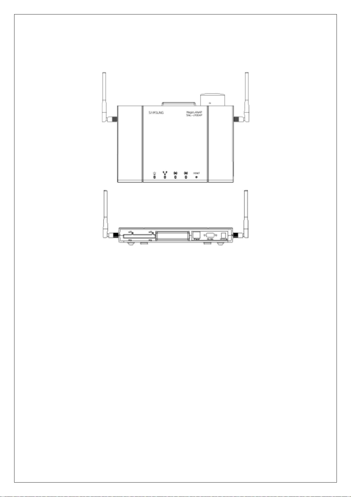
AP View
! The Front and Rear View of SWL-4000AP
Power
Ethernet
Wireless A
Wireless B
Reset
PCMCIA Slot B
PCMCIA Slot A
DC in
RJ-45 Connector
RS-232C
! The Front and Rear View of SWL-4000AP(DA)
1
2

2. Installation
① Choose the place with the consideration of power outlet and network
connection (RJ-45 Cable connection) to install the Access Point.
② Plug in the power cord to the power outlet and the power adapter.
Plug in the DC output to “DC in”. Make sure that the “Power” LED is on. If the
“Power” LED is not on, please check the connections of the power cord.
Notice : Use the supplied power adapter(DC 5V, 2A) only to prevent the
permanent failure of AP.
③ Confirm that “Wireless” LED of AP blinks.
If not, confirm that Wireless LAN Card of AP is properly mounted in case for
4000AP and 4000AP(DA). The card should be inserted or extracted when the
power is off, and we are not responsible for any product failure due to
disassembly by users.
Notice : Use the supplied Wireless LAN card(3.3V) only to prevent the
permanent failure of AP.
④ Attach UTP Ethernet cable to the RJ-45 Connector.
Make it sure that the “Ethernet” LED is on. If the “Ethernet” LED is on, you
can use the existing network with the Access Point; otherwise check the UTP
cable connections.
⑤ Attach RS-232C serial cable to the Access Point and the PC.
The parameters of Access Point can be configured through the connection of
RS-232C serial cable to the PC(Refer to Chapter 17).
⑥ When AP Manager is used, you may skip the step ⑤.
⑦ Change settings of AP according to user’s selection referring User’ s Guide.
3
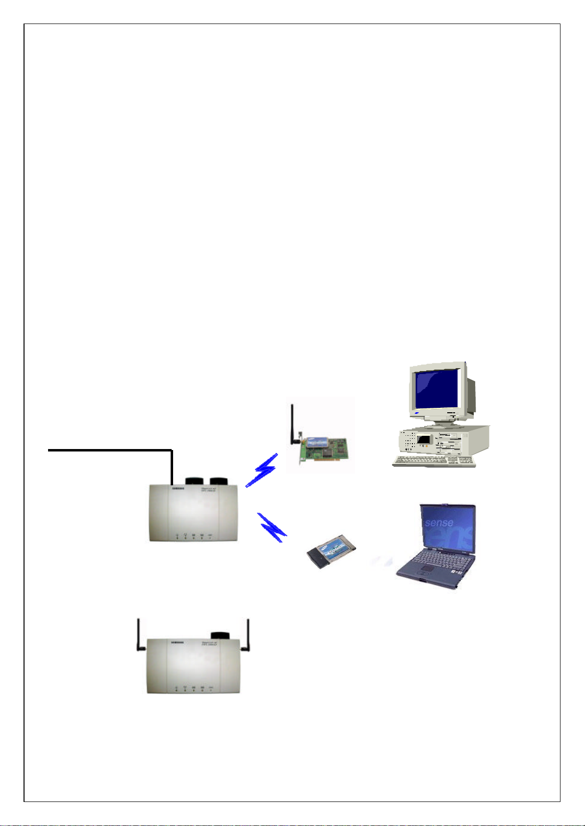
⑧ Insert Wireless LAN Card into your PC.
Wireless LAN Cards are available both for desktop and notebook PCs. PCI
Wireless LAN Card is used for the desktop PC where as the PCMCIA Wireless
LAN Card is for the notebook PC only. For more information about PCI and
PCMCIA Wireless LAN Cards, please visit http://www.magiclan.com .
⑨ Enter the same ESSID that you have set for the Access Point, using the
Wireless LAN Card utility running on your PC.
⑩ Through AP, which is installed and set by the method above, you can
communicate between server and PC with installed Wireless LAN Card.
Ethernet, ADSL,
and Cable Modem
[Models subjected to this User’s Guide]
SWL-4000AP
SWL-4000AP(DA)
4
3
3. AP Basic Setting Using AP Manager
33
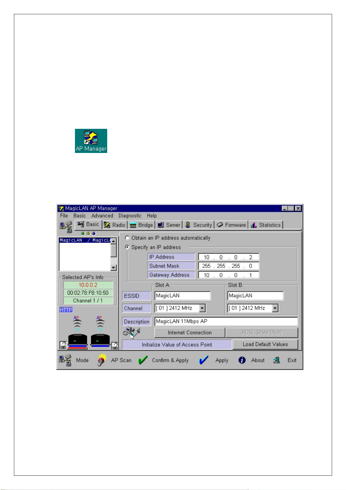
① Execute AP Manager(SWL-3000AP Series, 4000AP Series Management
Utility) under MS-Windows 95/98/Me/2000/NT/XP operating system.
② After choosing AP, which will be used by users, on “List Box” of AP Manager
using mouse, select [Basic] tab for any changes on setting.
③ AP information of the selected AP will appear on [Selected AP’s Info] Group
Box. You may refer to APPENDIX Ⅰ for detailed explanation.
5
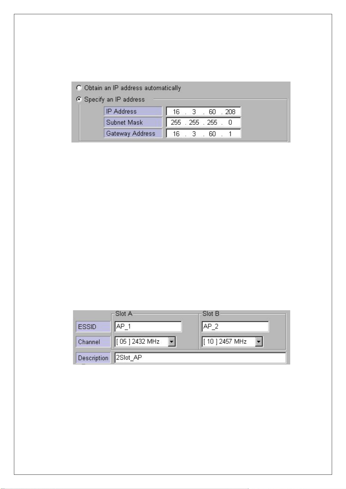
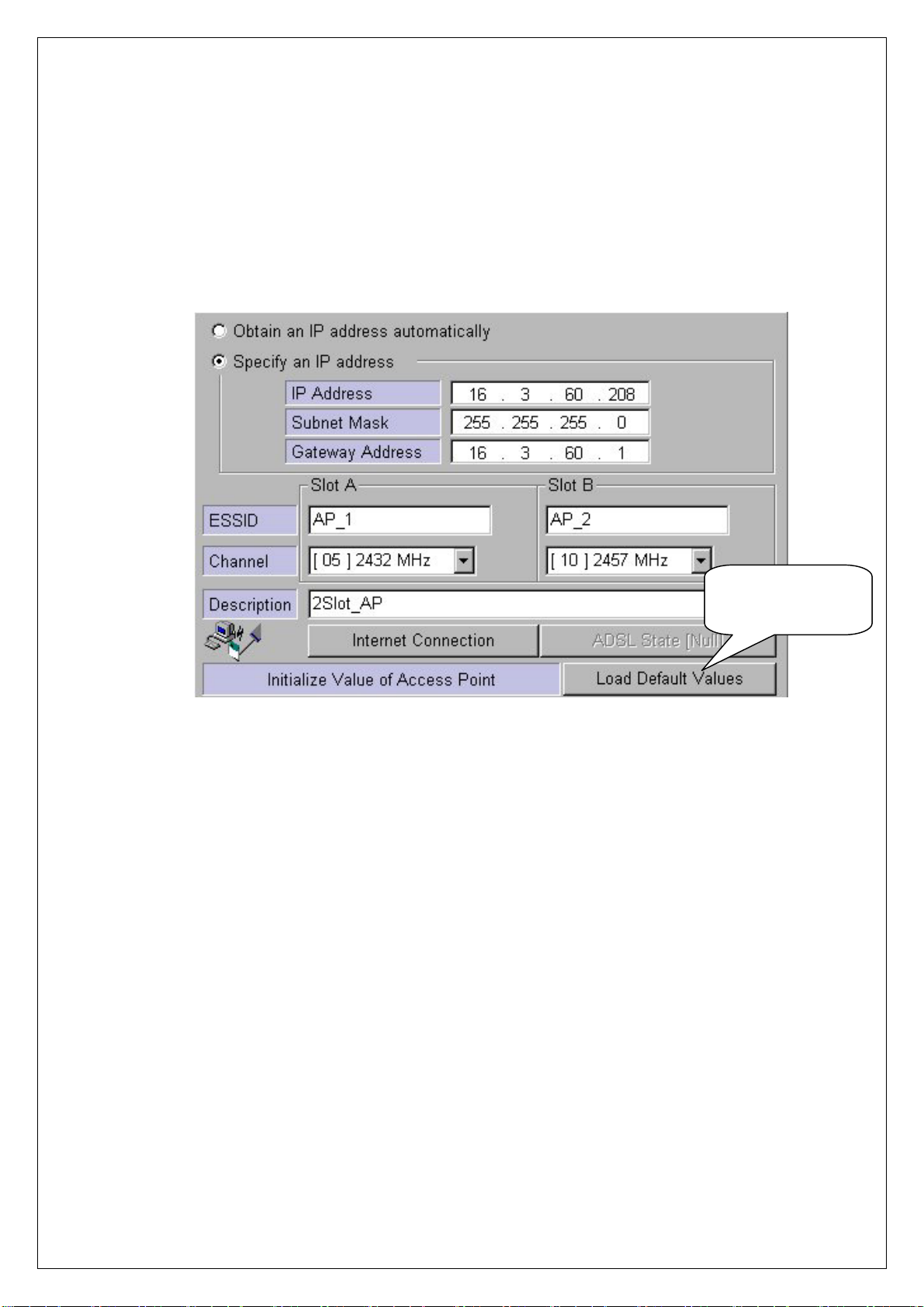
④ TCP/IP address environment is set on [Basic] Dialogue Box.
♦ Specify an IP address
After consulting with your system administrator, you enter IP Address,
Subnet Mask and Gateway Address.
♦ Obtain an IP address automatically
This setting is possible when AP is used for DHCP Client.
⑤ Set ESSID and Channel number. Description is a parameter not related with
any operation, and it is used only to record description or stored location of AP.
We recommend you use different ESSID and Channel for each slots
♦ Set ESSID for AP use.
ESSID (Max. 32 Characters) must consist of alphabetic and numeric
characters excluding blank and special characters(Capital•Small letter
distinction).
6
♦ Set Channel for AP use.
Channel index should be between 1 and 14(differs from country to country).
Notice : If you are operating two or more Access Points in the adjoining
cells, keep the appropriate channel distance to avoid the interference. We
recommend you to keep the distance of at least 4 channels in the adjoining
cells.
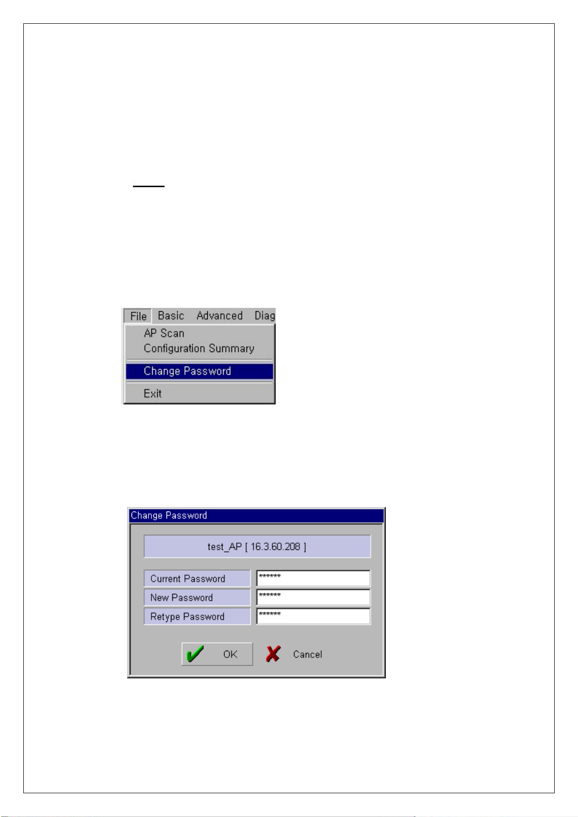
⑥ Select “Change Password” on [File] menu if you want to change the password.
⑦ After entering Current Password, New Password and Retype Password, click
[OK] button.
Please keep this password at a safe place or keep it where it may not get lost.
7
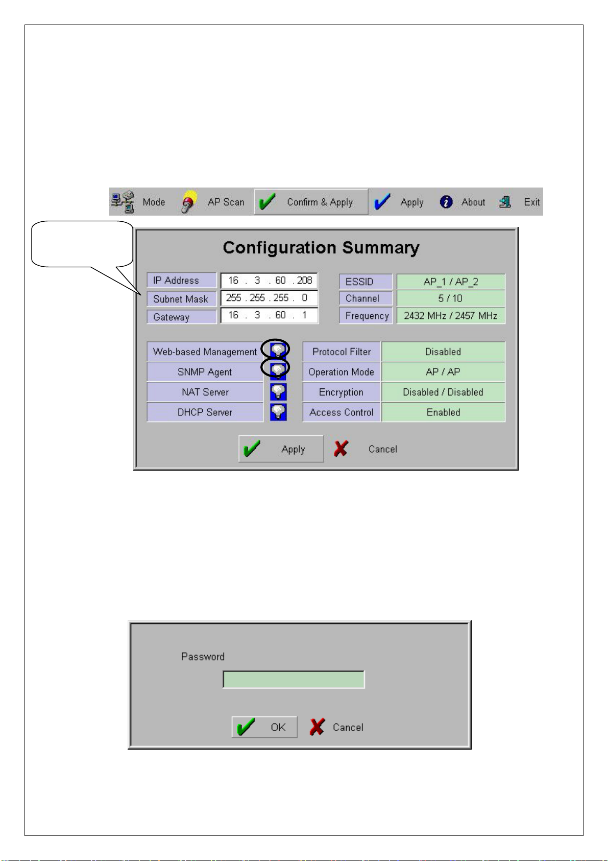
⑧ When you click [Confirm & Apply] button to apply new configuration,
Confirm New
Configuration
“Configuration Summary” window, which shows new configuration, will
appear.
⑨ If new settings are entered correctly, click [Apply] button to apply new
configuration.
⑩ When you click [Appl y] button, “Password” win dow will appear. The default
password is “public”, and user can change password later.
8
⑪ After you enter the password, click [OK] button.
⑫ If you want to set default values, click [Load Default values] button. Then, AP
Configuration will return to default setting.
Resetting to
Default Values
9
4. PTP Setting Using AP Manager
① PTP stands for Point to Point, and it is used to connect two divided networks
into one using one slot of AP as Wireless Bridge. In this case, the other slot is
used for capabilities of Access Point.
(Hub)
< AP Slot Area>
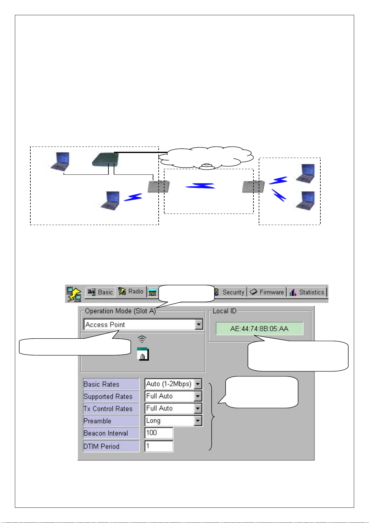
② After executi ng AP Man ager, select [Radi o] tab o n “Tab Bar”. S elect slot t o set
PTP on “List Box” using mouse(by click the shape of Wireless LAN Card), and
Internet Network
< Point to Point Area>
< AP Slot Area>
confirm setting status on [Radio] Dialogue Box.
Confirm AP Operation Mode
Confirm Slot
MAC ID of Wireless LAN
Card on Selected Slot
“Default Values”
Recommended
10
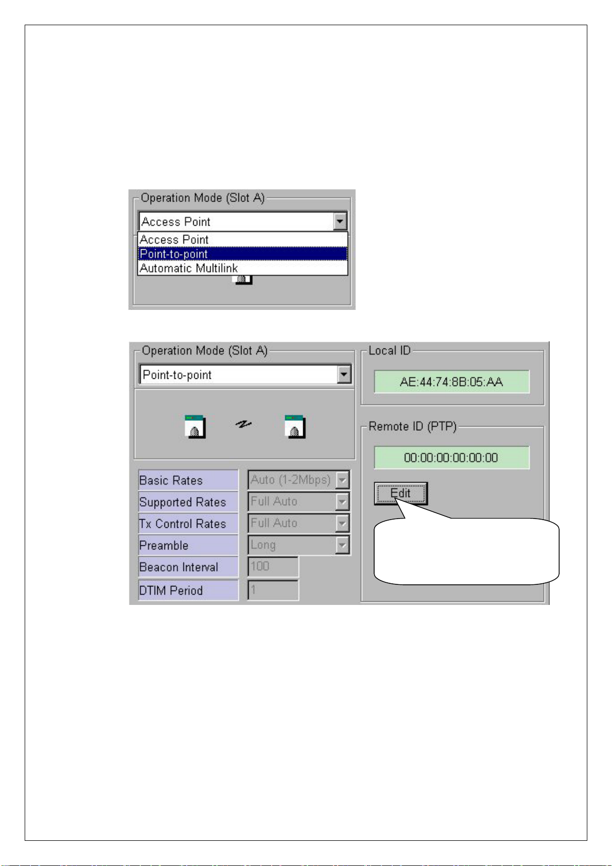
③ When Operation Mode of AP is selected for “Point-to-Point” on [Radio]
Dialogue Box, [Remote ID (PTP)] Box will appear to enter MAC ID of
Wireless LAN Card on other AP, which will be connected by using PTP mode.
Setting MAC ID of other
Wireless LAN Card to be
Connected Using PTP Mode
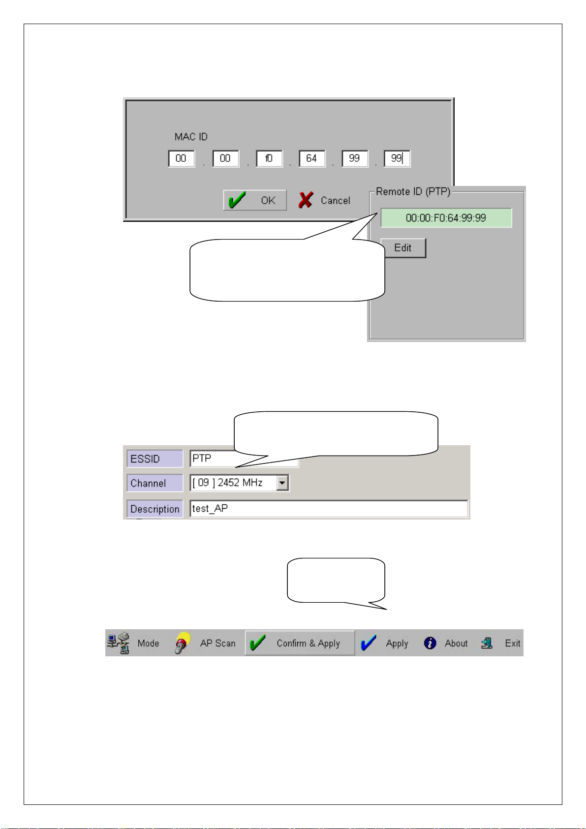
④ When [Edit] button on [Remote ID (PTP)] Box is selected, [MAC ID] Box,
which is to enter(for entering) MAC ID of Wireless LAN Card of other AP to
be connected, will appear. After entering MAC ID, click [OK] button to
complete setting. MAC ID setting can be confirmed on [Remote ID (PTP)] Box.
11
f
Confirm MAC ID Setting o
other Wireless LAN Card to be
connected using PTP Mode
⑤ ESSID and Channel of two APs must be identical in PTP mode
Enter the Same ESSID and
Channel of two APs in PTP Mode
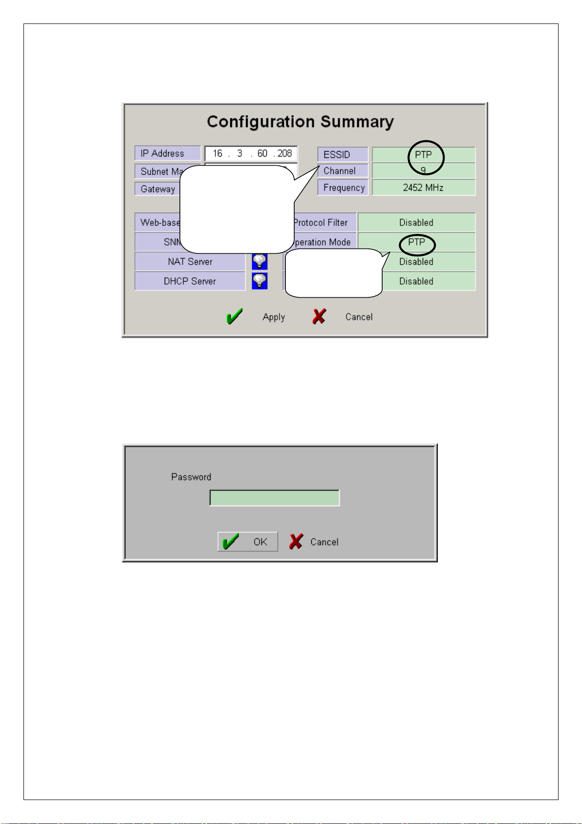
⑥ When you click [Confirm & Apply] button to apply new configuration,
“Configuration Summary” window, which shows new configuration, will
Confirm PTP
Mode Setting
appear.
12
Confirm Common
ESSID and
Channel for AML
Mode Setting
Confirm AML
Mode Setting
⑦ If new settings are entered correctly, click [Apply] button to apply new
configuration.
⑧ When you click [Apply] button, “Password” window will appear.
⑨ After you enter the password, click [OK] button.
⑩ When you click [Apply] button instead of [Confirm & Apply] button,
“Password” window will appear immediately skipping “Configuration
Summary” window. After you enter the password, click [OK] button to apply
new configuration.
13
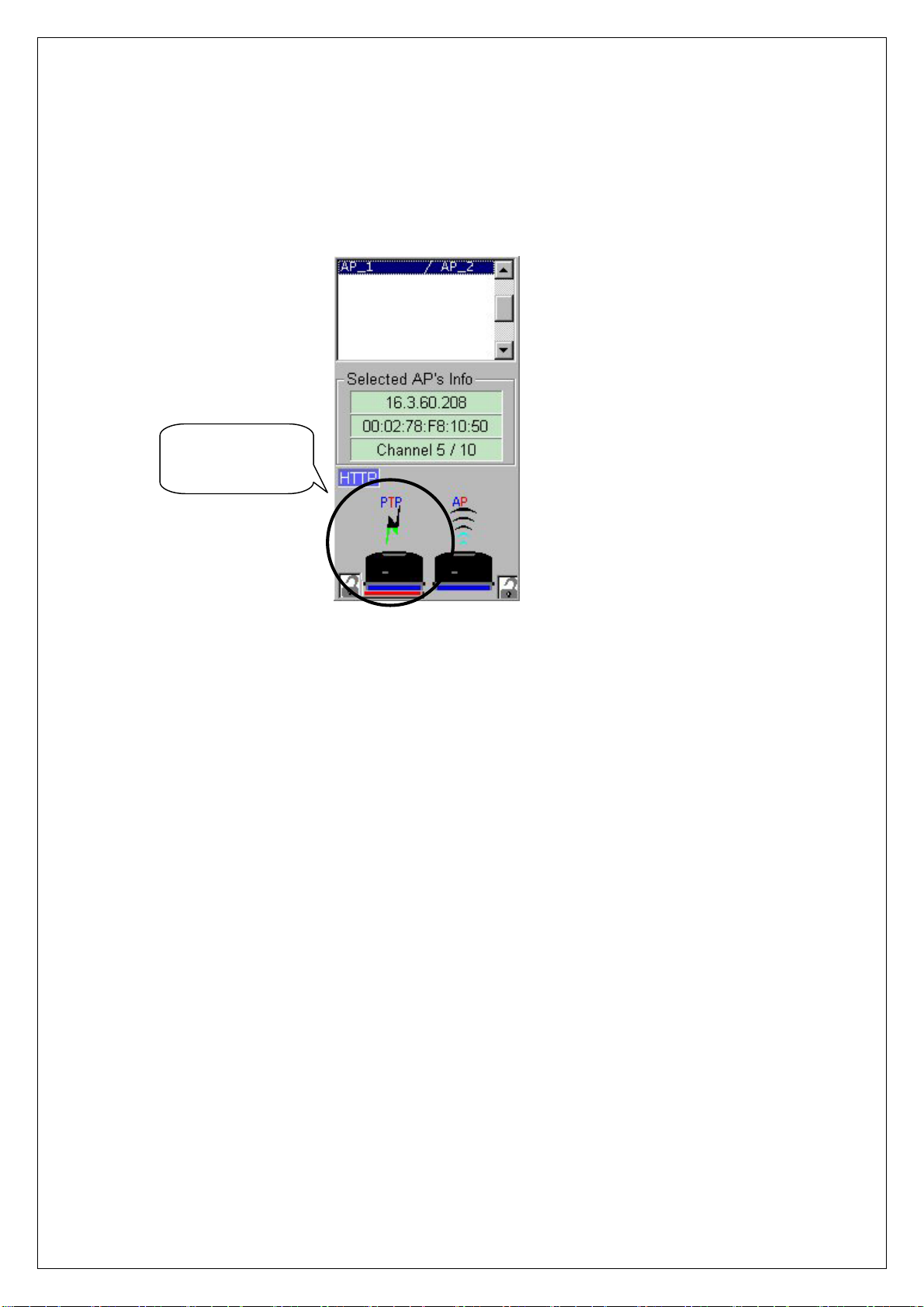
⑪ After rebooting, choose selected proper AP on “List Box”. Then, the selected
slot set with PTP Mode can be confirmed on [Selected AP’s Info] Group Box
as shown below.
Confirm PTP
Mode Setting
14
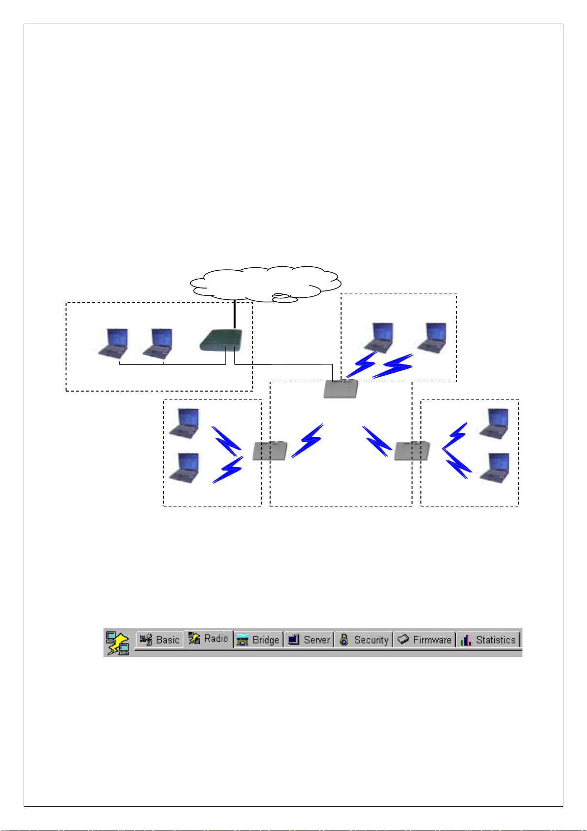
5. AML Setting Using AP Manager
① AML stands for Automatic Multi-link. Using one slot of AP as Wireless Bridge
and the other as Access Point, it is used to connect several divided networks
into one. It connects several [Slave]s with one main [Master]. In this case, you
can consist Wire Network by connect Hub to Ethernet Port of AP or can
connect Ethernet, ADSL and Cable Modem to it.
(Hub)
<Wire Network using Hub>
<AP Slot Area>
② After executing AP Manager, click [Radio] tab on “Tab Bar”. After selecting
slot to set AML on “List Box” using mouse(by click the shape of Wireless
Internet Network
<AML Slot Area>
<AP Slot Area>
[Master]
[Slave] [Slave]
<AP Slot Area><AP Slot Area>
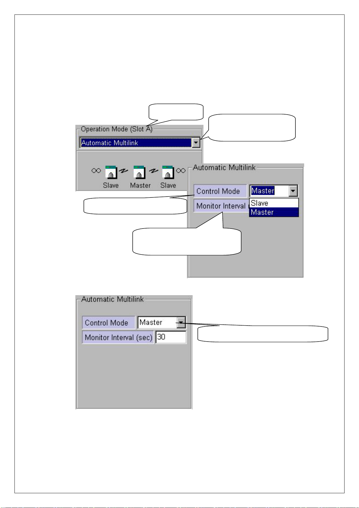
LAN Card), set Operation Mode with “Automatic Multi-link” on [Radio]
Dialogue Box.
③ When “Automatic Multi-link” on [Radio] Dialogue Box is selected, [Automatic
Multi-link] Box, which sets AP status(Master or Slave) in AML mode, will
appear.
15
r
④ Select either “Master” or “Slave” for [Control Mode] on [Automatic Multi-link]
Box. Basically, AML Mode consists of two or more APs, and set one for
“Master” and the rest for “Slave”s.
Confirm Slot
Confirm AP Operation
Mode Setting
Setting AML Control Mode
Default Value for “Monito
Interval” Recommended
Confirm AML Control Mode Setting
16
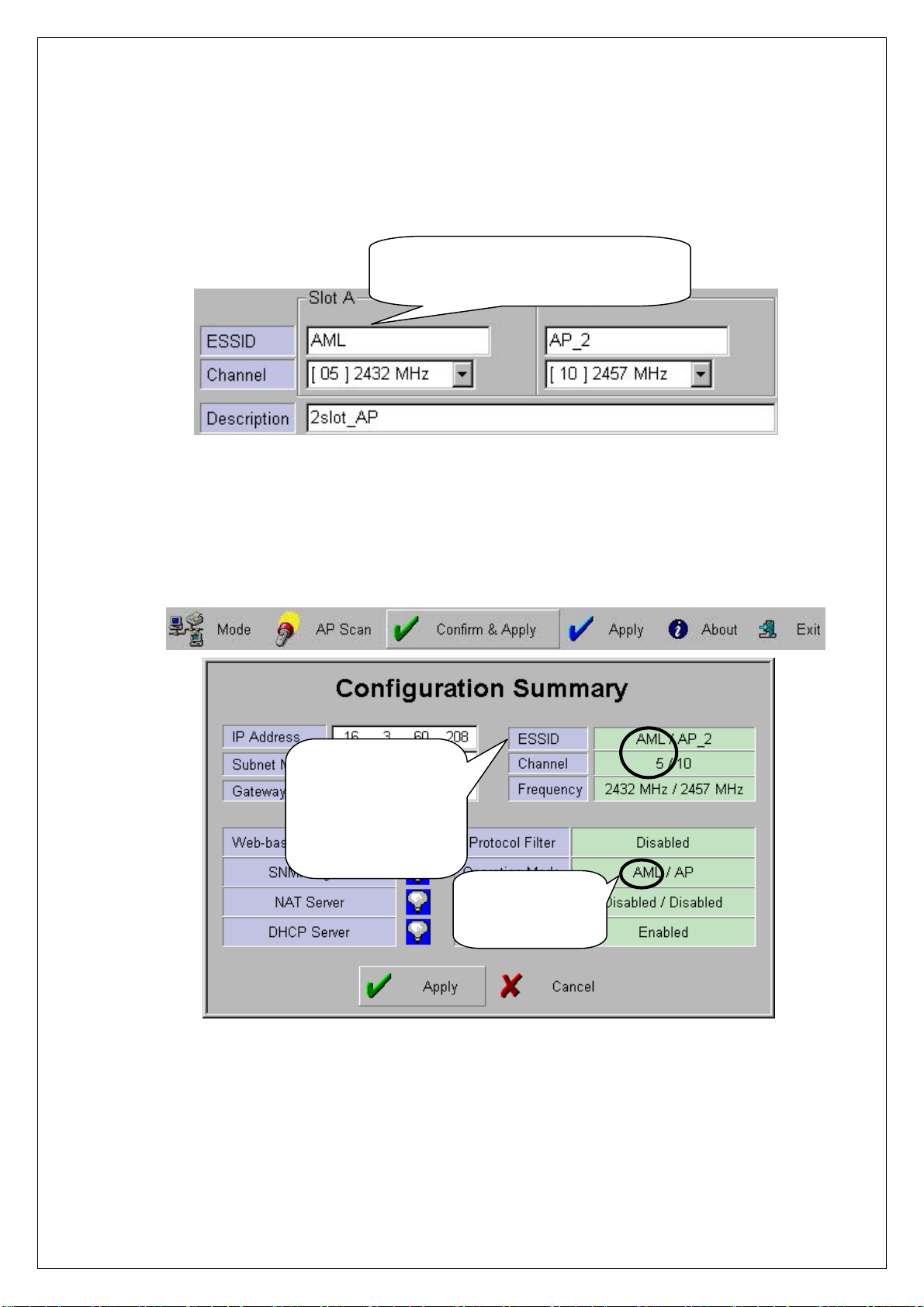
⑤ All of ESSID and Channel of AP set in AML mode must be identical.
Enter the Same ESSID and
Channel of all APs in AML Mode
⑥ When you click [Confirm & Apply] button to apply new configuration,
“Configuration Summary” window, which shows new configuration, will
appear.
Confirm Common
ESSID and
Channel for AML
Mode Setting
Confirm AML
Mode Setting
⑦ If new settings are entered correctly, click [Apply] button to apply new
configuration.
17
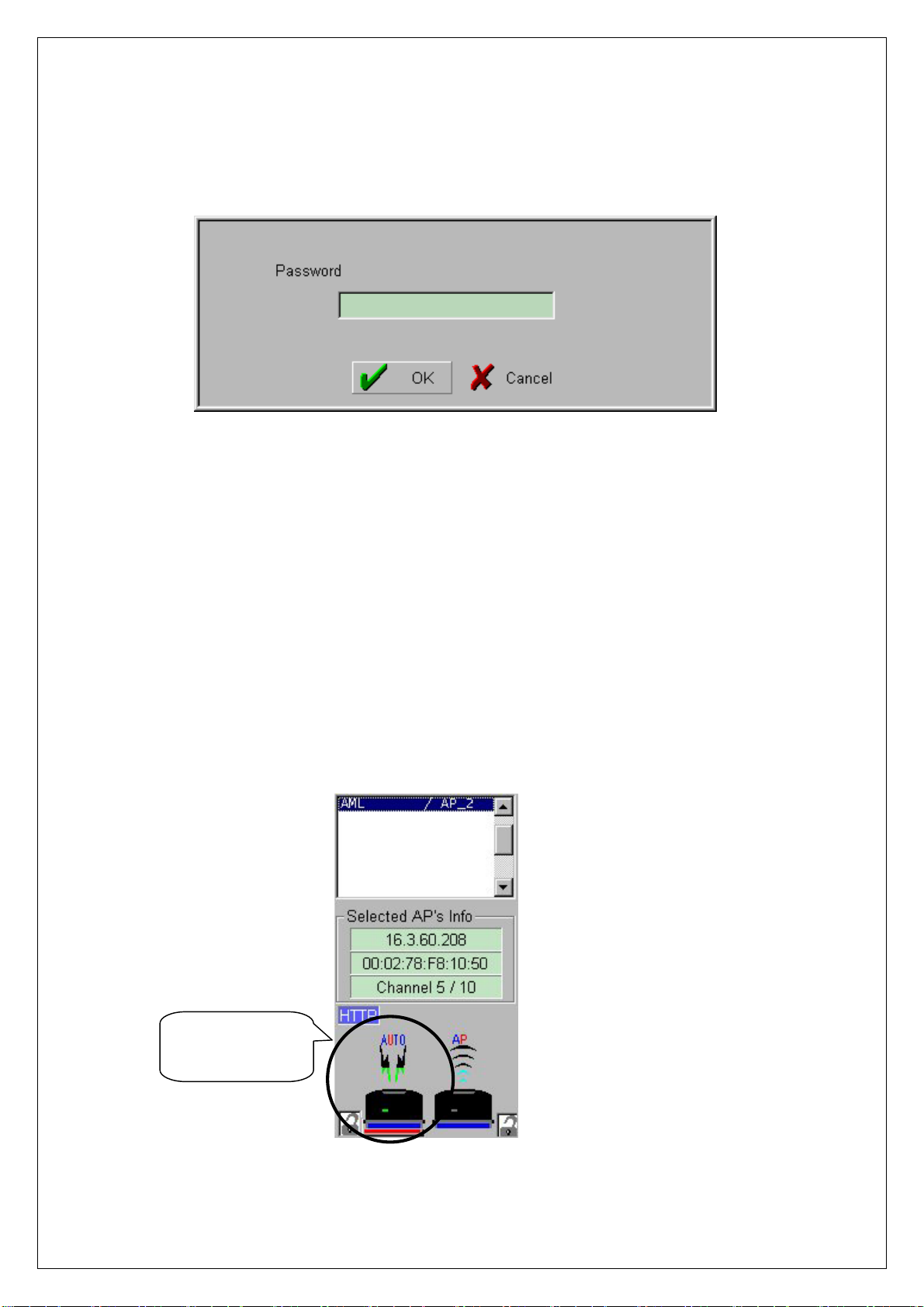
⑧ When you click [Apply] button, “Password” window will appear.
⑨ After you enter the password, click [OK] button.
⑩ When you click [Apply] button instead of [Confirm & Apply] button,
“Password” window will appear immediately skipping “Configuration
Summary” window. After you enter the password, click [OK] button to apply
new configuration.
⑪ After rebooting, choose selected proper AP on “List Box”. Then, the selected
slot set with AML Mode can be confirmed on [Selected AP’s Info] Group
Box as shown below.
Confirm AML
Mode Setting
18
6. Bridge Table and Protocol Management Using AP
Manager
① Using AP Manager, list of Wired and Wireless Station(PC or AP) connected to
current AP can be confirmed. Also, it sets type of Protocol to receive and send
selected data, which satisfy Protocol user wants, among data transmitting
through AP.
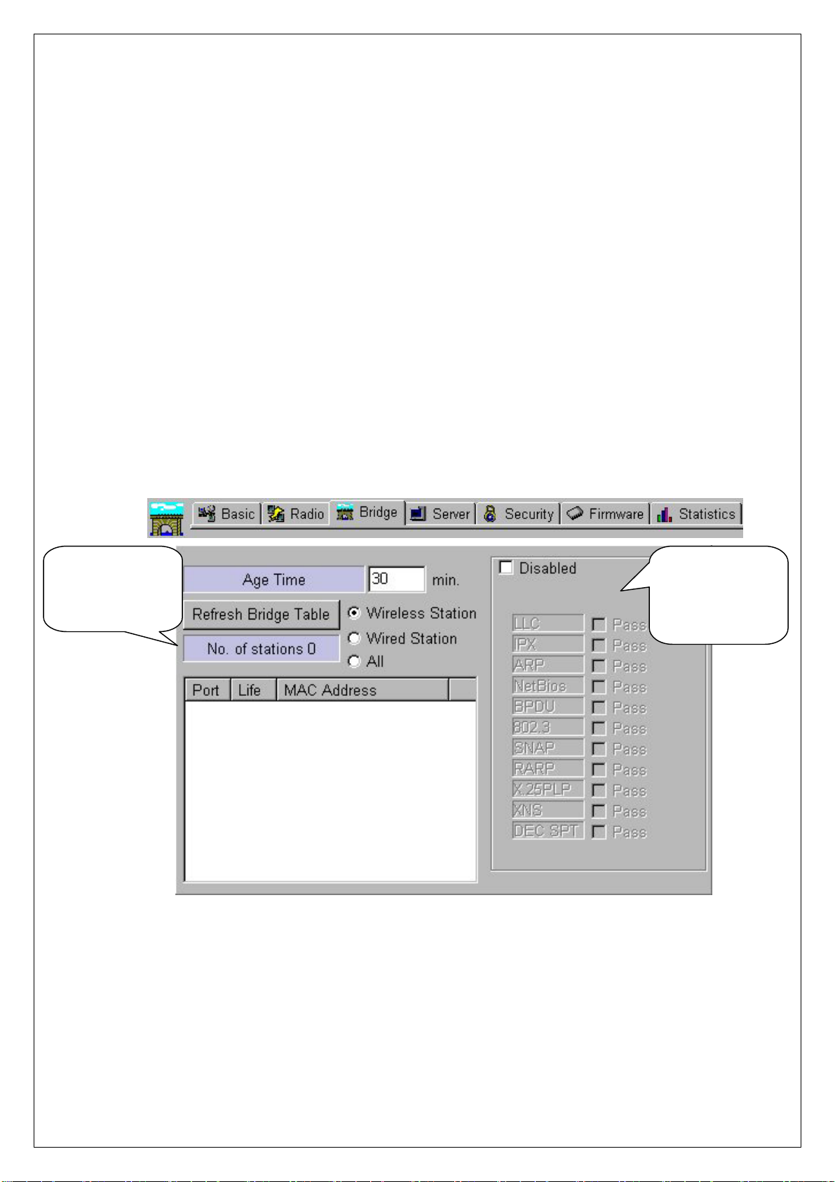
② When you select [Bridge] tab on “Tab Bar” of AP Manager, two boxes, which
manage “Bridge Table” and “Protocol” on Dialogue Box, will appear.
Bridge Table
Management
Protocol
Management
Box
③ AP enables receiving and sending of data by managing currently connected
Wired and Wireless Stations with “Bridge Table” consisting values of MAC
Address form.
19
④ [Age Time] on [Bridge Table] Management Box shows cycle of AP refre shing
“Bridge Table”. The use of Default Values is recommended.
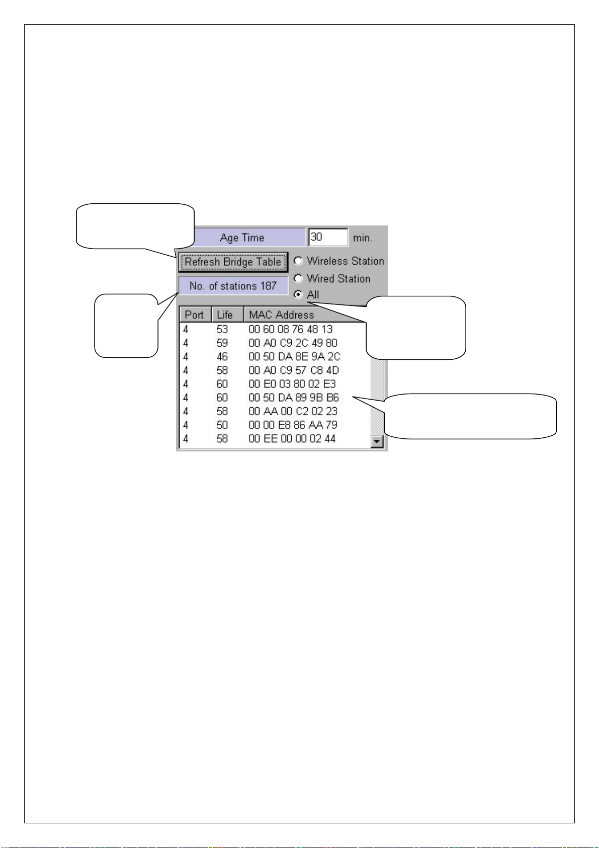
⑤ After selecting Station Type you want with Radio button to refresh Stations
connected to current AP, click [Refresh Bridge Table] button to confirm.
Confirm Refresh
Bridge Table
Number
of
Stations
Radio Button
for Selecting
St ation Type
MAC Address Information
of Connected Stations
⑥ [Bridge Table] Management Box enables confirmation of Wired and Wireless
Stations connected with current AP only.
⑦ You can block Protocol you do not want using [Protocol] Management Box.
When Protocol use is limited, some specific applications may not operate.
Therefore, before setting, consult your system administrator. “Disabled” of
Default Value is recommended.
⑧ Selecting “Disabled” checkbox on [Protocol] Management Box leads to
“Enabled”. Then, whole [Protocol] Management Box is activated to enable
selecting.
⑨ If you select any Protocol what you do not want among Protocols shown on
[Protocol] Management Box, a phrase of “Pass” changes to “Drop”.
20
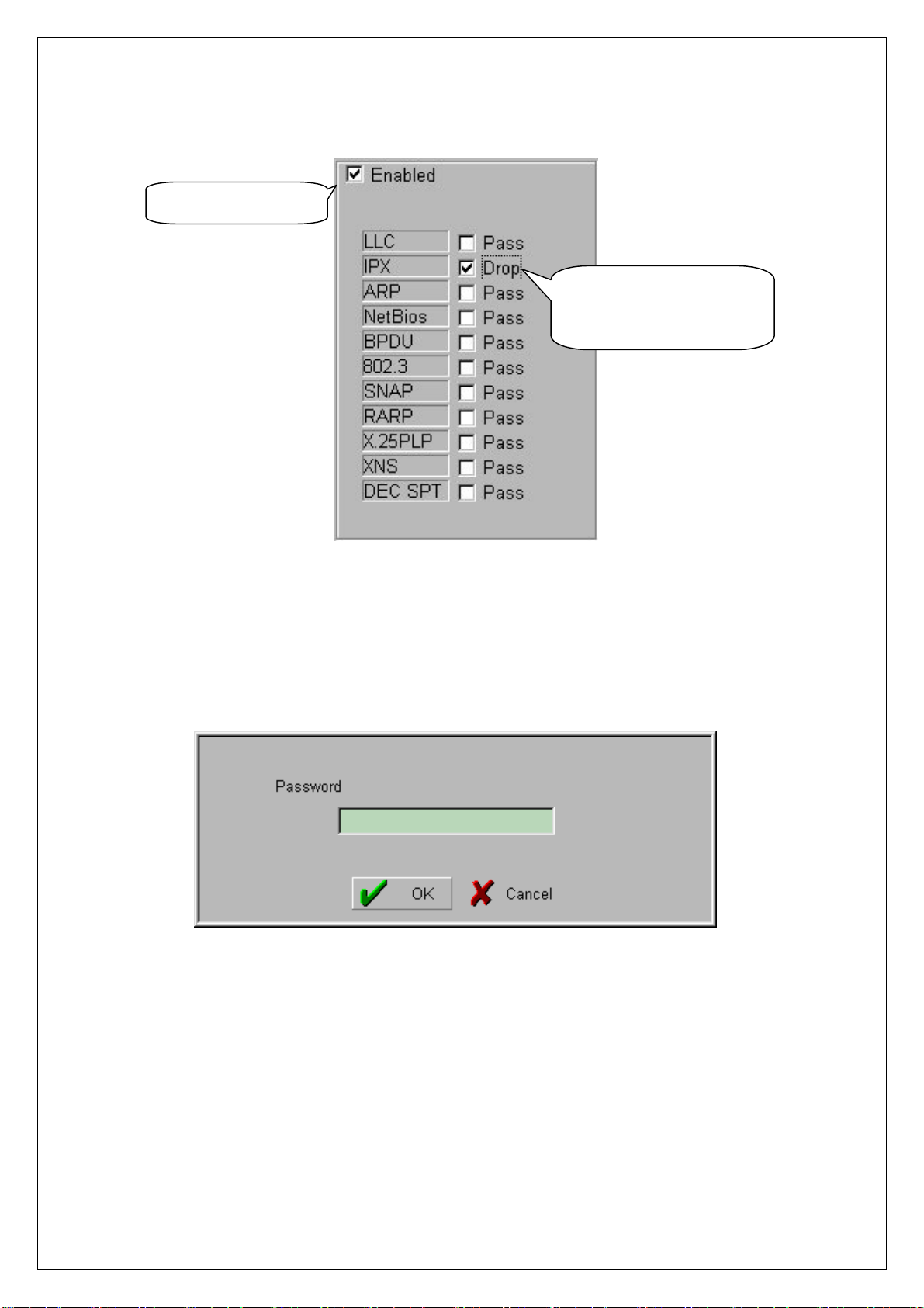
Select “Enabled”
Select Protocol Which
You Do Not Want
⑩ If new settings are entered correctly, click [Apply] button to apply new
configuration.
⑪ When you click [Apply] button, “Password” window will appear.
⑫ After you enter Password, click [OK] button.
21

7. NAT Setting Using AP Manager
① NAT stands for Network Address Translation, an d it is used to establish private
network domain. Using NAT, any desktop or notebook PC, which are
connected to AP, may freely use any private IP Address. In this case, the
private IP Address must have same Network Address assigned for NAT IP
Address.
For Example) NAT IP Address : 172.16.0.1
Station IP Address #1 : 172.16.0.100
Station IP Address #2 : 172.16.0.150
In this case, Network Address is 172.16.0.X.
② After you select [Server] tab of AP Mana ger, selec t [ NAT] on Dialogue Box . In
this case, enter Gateway Address you select on “IP Address” of [NAT]. The
default setting value is “172.16.0.1”.
Select [Server] Tab
NAT Setting
IP Address and
Subnet Mask Setting
22
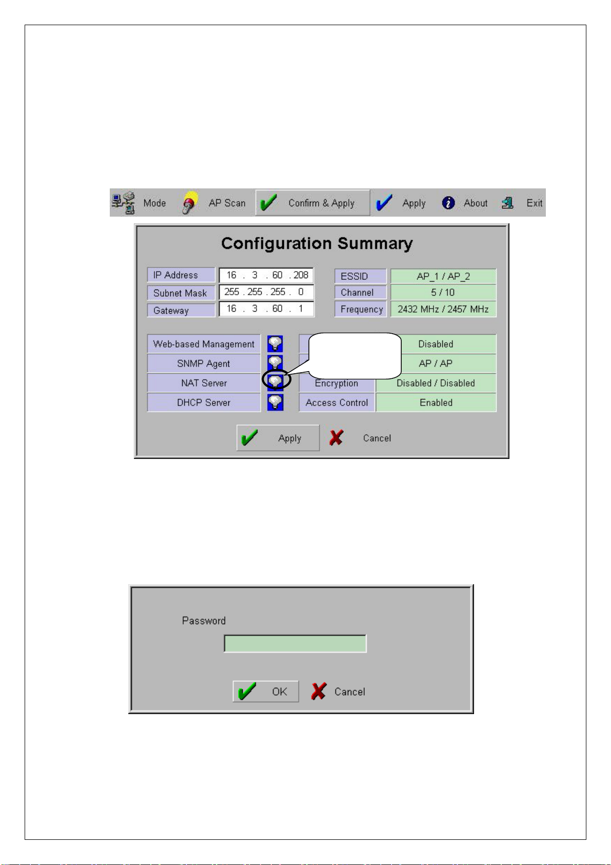
③ When you click [Confirm & Apply] button to apply new configuration,
“Configuration Summary” window, which shows new configuration, will
appear.
Confirm NAT
Setting
④ If new settings are entered correctly, click [Apply] button to apply new
configuration.
⑤ When you click [Apply] button, “Password” window will appear.
⑥ After you enter the password, click [OK] button.
23
 Loading...