

Wireless Receiver
Module
Model Name : SWA-5000
Model Code : SWA-5000/XEF
SERVICE
Manual
Wireless Receiver Module
CONTENTS
1. Precaution
2. Product Specification
3. Disassembly & Reassembly
4. Troubleshooting
5. Exploded View & Part List
6. PCB Diagram
7. Schematic Diagram
SWA-5000
Refer to the service manual in the GSPN (see the rear cover) for the more information.
GSPN (Global Service Partner Network)
Area Web Site
North America service.samsungportal.com
Latin America latin.samsungportal.com
CIS cis.samsungportal.com
Europe europe.samsungportal.com
China china.samsungportal.com
Asia asia.samsungportal.com
Mideast & Africa mea.samsungportal.com
This Service Manual is a property of Samsung Electronics
Co.,Ltd. Any unauthorized use of Manual can be punished
under applicable International and/or domestic law.
© Samsung Electronics Co.,Ltd. Aug. 2010
Printed in Korea

Contents
1. Precaution
1-1 Safety Precautions ...........................................................................................1-1
1-2 Servicing Precautions ......................................................................................1-3
1-3 Precautions for Electrostatically Sensitive Devices (ESDs) .............................1-4
2. Product Specification
2-1 Product Feature ...............................................................................................2-1
2-2 Specifications ...................................................................................................2-2
2-3 Specifications Analysis .....................................................................................2-3
2-4 Accessories ......................................................................................................2-4
3. Disassembly & Reassembly
3-1 Overall Disassembly & Reassembly ................................................................3-1
4. Troubleshooting
4-1 Checkpoints by Error Mode.............................................................................. 4-1
4-2 Initialization Methods........................................................................................ 4-9
5. Exploded View & Part List
5-1 Exploded View .................................................................................................5-1
5-2 Electrical Part List ............................................................................................5-3
6. PCB Diagram
6-1 Wiring Diagram ................................................................................................6-1
6-2 MAIN PCB Top .................................................................................................6-2
6-3 MAIN PCB Bottom ...........................................................................................6-4
7. Schematic Diagram
7-1 Overall Block Diagram .....................................................................................7-1
7-2 AMP-1 ..............................................................................................................7-2
7-3 AMP-2 ..............................................................................................................7-3
7-4 SMPS ...............................................................................................................7-4
7-5 LED ..................................................................................................................7-5

Product Specification
2. Product Specification
2-1 Product Feature
2.4GHz / 5.8GHz Dual Band
- WIRELESS SENSITIVITY : UNDER -75dBm
- delay time : UNDER 20mS
- Form Factor : Tx- SLOT TYPE dongle type, Included Rx
Interface
- Control : I2C
- Audio Data : I2S
Delay time : under 20ms
Noise Free (Automatically changing the frequency from the wireless interference)
Samsung Electronics 2-1
Product Specification
2-2 Specifications
Basic Specification
Model Name SWA-5000
Power Consumption 50W
Weight 2.52 lbs
Dimensions (W x H x D) 3 x 9 x 6 inches
Operating Temperature Range +41°F to +95°F
Operating Humidity Range 10% ~ 75%
Output Refer to the Owner’s Manual of the Samsung product.
Frequency range 20Hz ~ 20KHz
S/N Ratio 65dB
2-2 Samsung Electronics
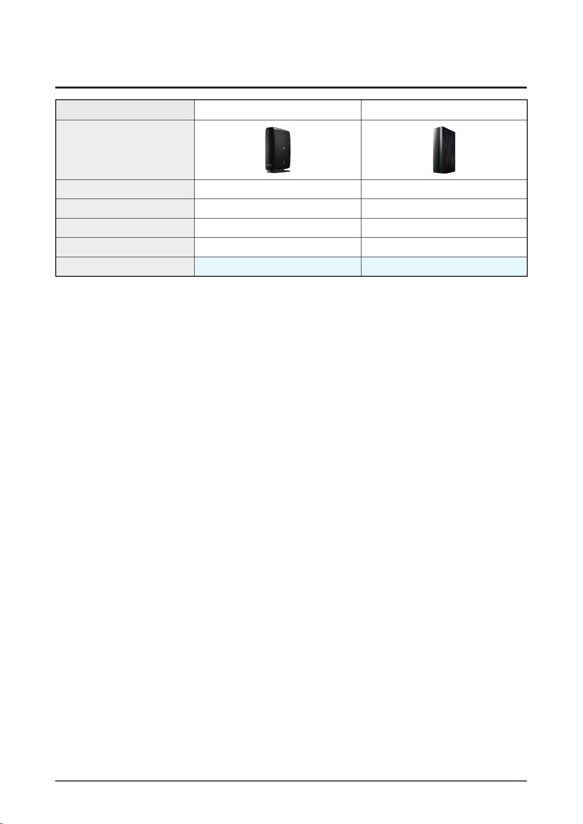
2-3 Specifications Analysis
Product Specification
Model Name
Photo
Total Power 330W 330W
# of channel 2ch 2ch
Distance at least 10m at least 10m
Antenna Not necessary Not necessary
Frequency 5.8 GHz Dual Band
SWA-4000 SWA-5000
Samsung Electronics 2-3
Product Specification
2-4 Accessories
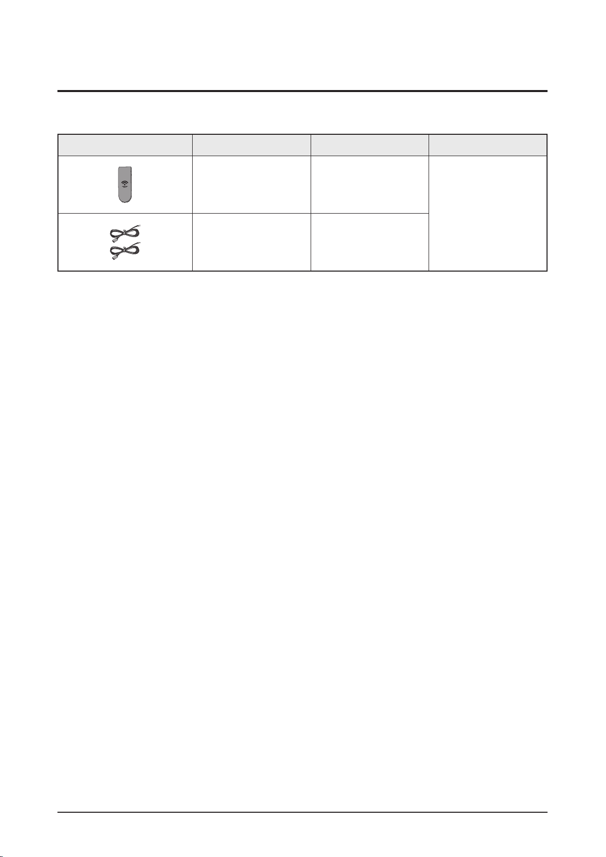
2-4-1 Supplied Accessories
Accessories Item Item code Remark
Tx Card AH40-00163A
Samsung Service center
Speaker Cable - 2EA AH81-02137A
2-4 Samsung Electronics
Disassembly & Reassembly
3. Disassembly & Reassembly
3-1 Overall Disassembly & Reassembly
- Be careful to follow the disassembly sequence described in the manual. Otherwise, the product
may be damaged.
- Be sure to carefully read and understand the safety instructions before performing any work as
the IC chips on the PCB are vulnerable to static electricity.
- In order to assemble reverse the order of disassembly.
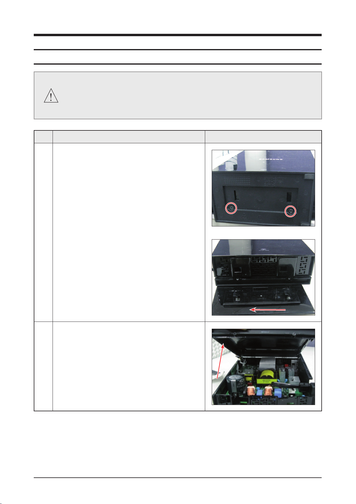
No. Description Description Photo
1 1) Unfasten 2 screws on the Rear
: BH,+,-,B,M3,L10, ZPC. (BLK 6003-001246)
2) Remove STAND.
2 1) Remove CABINET-RIGHT.
Samsung Electronics 3-1
3-2 Samsung Electronics
Disassembly & Reassembly
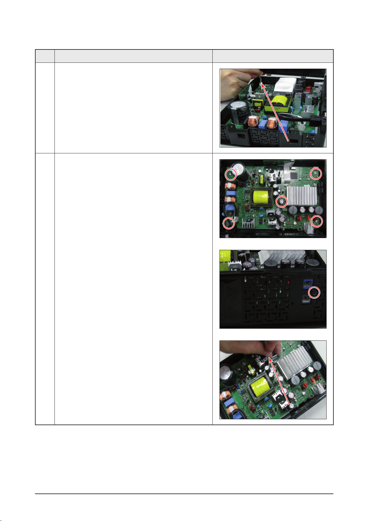
No. Description Description Photo
2 2) Pull out line.
3 1) Unfasten 5 screws on the Rear
: BH,+,-,B,M3,L10, ZPC. (WHITE 6003-000276)
2) Unfasten 1 screw on the Rear
: BH,+,-,B,M3,L10, ZPC. (blk 6003-000275)
3) Pull out line.
Disassembly & Reassembly
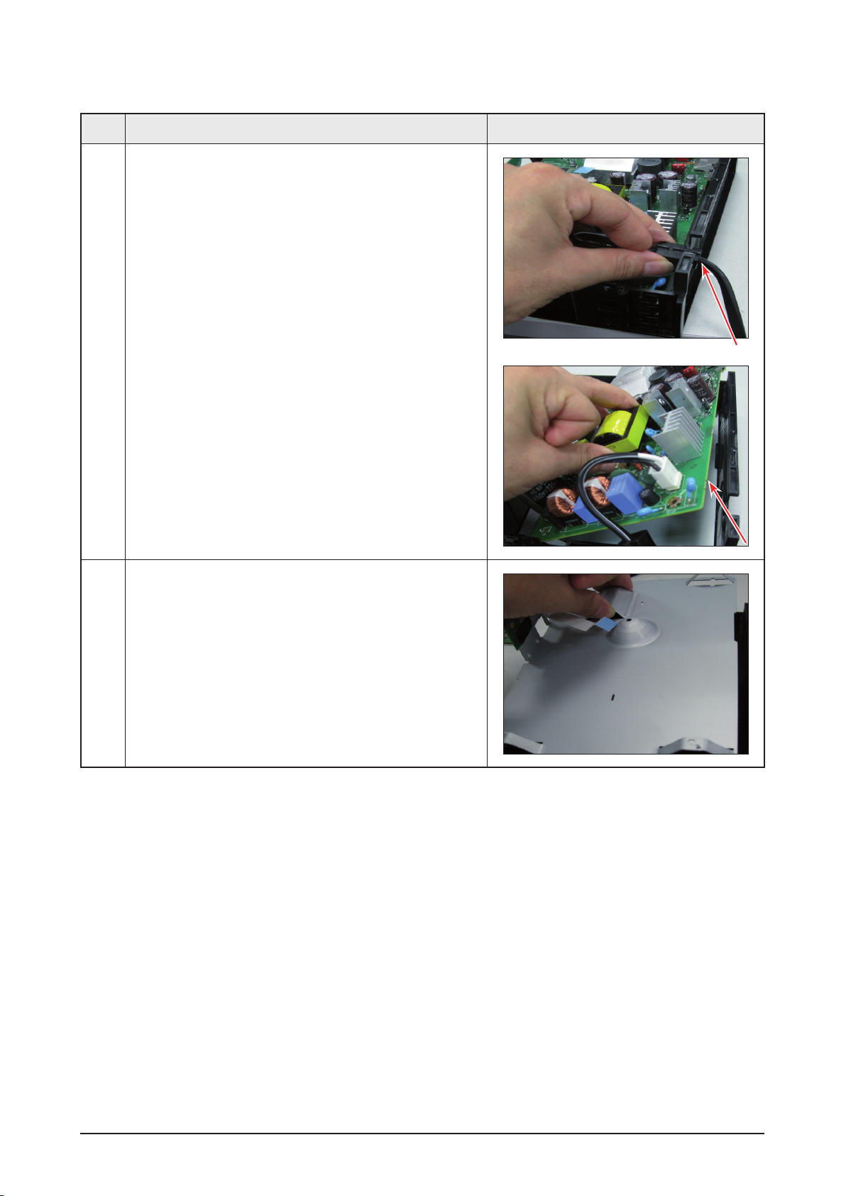
No. Description Description Photo
3 4) Remove electric iron.
5) Remove ASSY-PCB-MAIN.
4 1) Unfasten 1 screw on the Rear
: BH,+,-,B,M3,L6,ZPC. (WHITE)
Samsung Electronics 3-3

MEMO
3-4 Samsung Electronics
Exploded View & Part List
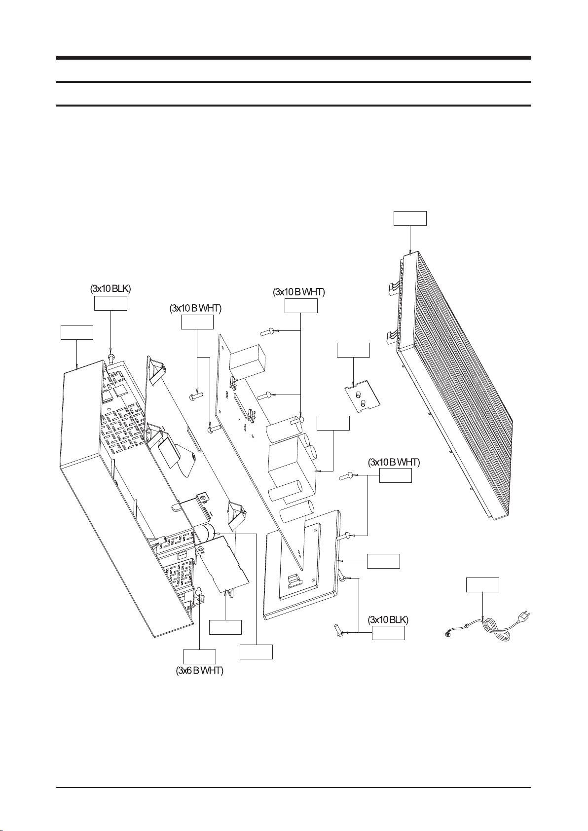
RC01
ML01A
RC04
MOD1
W384
W384
W390
W390
W390
W275
RB02
T0268
FL261
MA02A
5. Exploded View & Part List
5-1 Exploded View
5-1 Samsung Electronics
This Document can not be used without Samsung’s authorization.
Exploded View & Part List
Part List
Loc. No. Part No. Description;Specification Qty. SNA Remark
FL261 3809-002516 FFC CABLE-FLAT;30V,80C,90mm,24P,0.5mm,UL 1 SA
MA02A AH94-02417A ASSY PCB AMP;SWA5000,ASSY PCB AMP,200 X 1 SA
ML01A AH94-02478A ASSY PCB LED-LED ASSY;SWA-5000,LED ASSY, 1 SA
MOD1 AH40-00164B RF MODULATOR;NAM-WM52,DSSS,10dBm,3.3~5V, 1 SA
RB02 AH61-03069A STAND-BOTTOM;SWA-5000,ABS,2.6,32,132,BLA 1 SNA
RC01 AH64-05269B CABINET-RIGHT;SWA-5000,PC,2.2,152,220 1 SNA
RC04 AH64-05268A CABINET-LEFT;SWA-5000,ABS,2.6,152,220,BL 1 SA
T0268 3903-000407 CBF-POWER CORD;AT,EU,CP2,HOUSING(2P),250 1 SA
W275 6003-001561 SCREW-TAPTYPE;BH,+,-,B,M3,L6,ZPC(WHT),SW 1 SA
W384 6002-000126 SCREW-TAPPING;FH,+,-,2S,M3,L10,ZPC(BLK), 3 SA
W390 6003-000276 SCREW-TAPTYPE;BH,+,-,B,M3,L10,ZPC(WHT),S 11 SA
Samsung Electronics 5-2
This Document can not be used without Samsung’s authorization.
 Loading...