

Samsung SVD-4300-N User Manual
High Strength
10X Zoom
SALES NETWORK
•
SAMSUNG TECHWIN CO.,LTD.
145-3, Sangdaewon-dong, Jungwon-gu, Seongnam-si, Gyeonggi-do, 462-120, Korea
TEL : +82-31-740-8151~8 FAX : +82-31-740-8145
•
SAMSUNG TECHWIN AMERICA,LTD.
1480 Charles Willard St. Carson, CA 90746, UNITED STATES
TEL : +1-310-632-1234 FAX : +1-310-632-2195
www.samsungtechwin.com
www.samsungcctv.com
•
SAMSUNG OPTO-ELECTRONICS UK,LTD.
Samsung House, 1000 Hillswood Drive, Hillswood Business Park
Chertsey Surrey KT16 OPS
TEL : +44-1932-45-5308 FAX : +44-1932-45-5325
P/No. : Z6806-0750-01D
VAN 08. 12
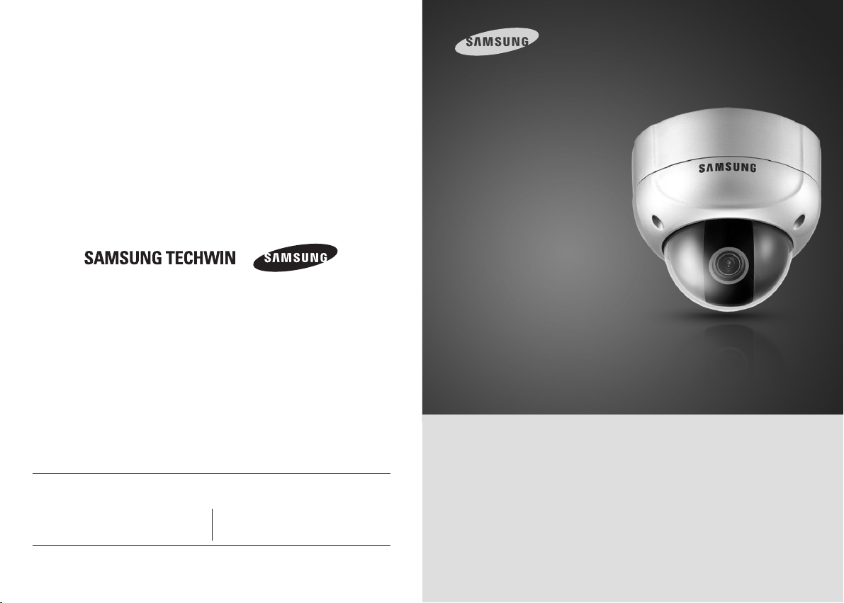
High-Resolution 10X Vandal-Proof Dome Camera SVD-4300
User’s Manual
Thank you for purchasing a SAMSUNG CCD CAMERA.
Before attempting to connect or operate this product,
please read these instructions carefully and save this manual for future use.
ENGLISH
Before operating the camera, confirm the camera model and proper input power
voltage. In order to that you can understand this manual thoroughly, we'll introduce
our model description.
■ SVD-4300 SERIES
•NTSC MODEL •PAL MODEL
SVD-4300(W)N SVD-4300(W)P
■ MODEL DESCRIPTION
• SVD-4300(W)X
__
CAMEA COLOR
• SIGNAL SYSTEM
NTSC MODEL
N
PAL MODEL
P
• CAMERA COLOR
SILVER COLOR
IVORY COLOR
W
SIGNAL SYSTEM
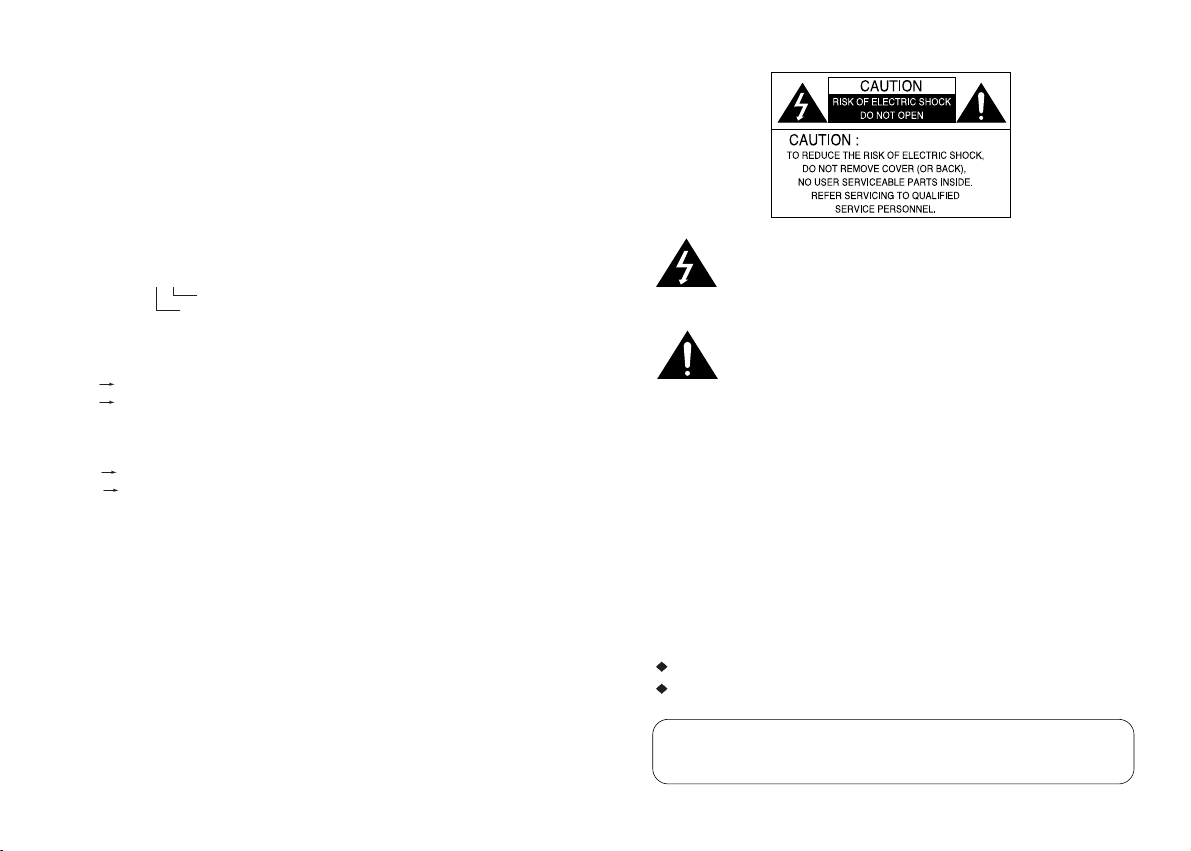
The lightning flash with an arrowhead symbol, within an equilateral triangle is
intended to alert the user to the presence of uninsulated “dangerous voltage”
within the product's enclosure that may be of sufficient magnitude to
constitute a risk of electric shock to persons.
The exclamation point within an equilateral triangle is intended to alert the user
to the presence of important operating and maintenance (servicing)
instructions in the literature accompanying the appliance.
INFORMATION -This equipment has been tested and found to comply with limits
for a Class A digital device, pursuant to part 15 of the FCC Rules. These limits are
designed to provide reasonable protection against harmful interference when the
equipment is operated in a commercial environment. This equipment generates,
uses, and can radiate radio frequency energy and, if not installed and used in
accordance with the instruction manual, may cause harmful interference to radio
communications.
Operation of this equipment in a residential area is likely to cause harmful
interference in which case the user will be required to correct the interference at
his own expense.
WARNING - Changes or modifications not expressly approved by the manufacturer
could void the user’s authority to operate the equipment.
WARNING - To prevent electric shock and risk of fire hazards:
Do NOT use power sources other than that specified.
Do NOT expose this appliance to rain or moisture.
This installation should be made by a qualified service person and
should conform to all local codes.
Features
A/F 10x Optical Zoom
The built-in SVD-4300 optical zoom lens is a
highly durable component. It features auto
focus, auto iris, and zoom functions.
SSNR (Samsung Super Noise
Reduction)
By using built-in SSNR function manufactured
by SAMSUNG TECHWIN, the amount of low
illuminance noise has been significantly
reduced, and the signal-to-noise ratio (S/N)
as well as horizontal resolution have been
improved, resulting in a clear and sharp
image display even in the dark.
High Sensitivity
The built-in high sensitivity COLOR CCD
enables a clear image even in 0.005Lux
(Sens-up, color) or lower illumination.
High Resolution
Featuring 500TV line horizontal resolution in
color mode and 570TV line horizontal resolution
in BW mode, the camera features Sony's
410,000 pixel CCD and captures clean,
noiseless, high-quality images.
Day & Night
The camera automatically determines whether
it is night time or day time, selecting operating
mode automatically. The camera operates in
color mode during day light conditions and BW
mode in night conditions for clearer identification.
IP66 Approved / Dust and Rain
Resistant
With dust and rain resistant design, the camera
can be installed outside under building eaves or
places that are exposed to the dust and rain.
RS-485 Function
The camera, using a RS-485 communication
can remote control relate to ZOOM/FOCUS
and OSD menu functions.
Sub Monitor Function
The sub monitor function enables easy
adjustment of the camera angle within the
monitoring range during its installation.
3-Axis camera mechanism
The SVD-4300 is especially incredibly flexible to
install with its 3-axis camera construction,
which makes the camera wall or slope mountable.
Miscellaneous Functions
Other miscellaneous functions of the camera
include privacy zone masking, digital zoom, line
lock synchronization(INT/LL), freeze, horizontal
inversion, and user-configured presets.
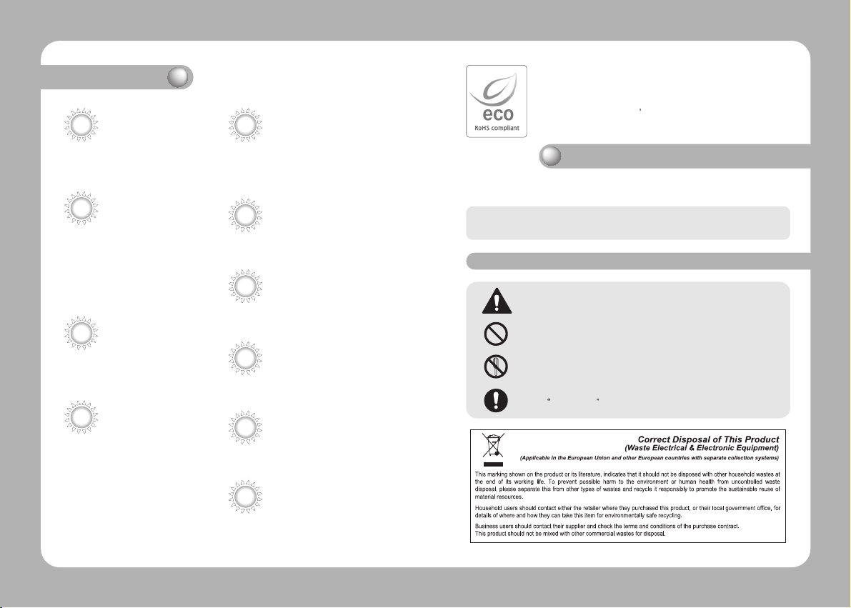
Samsung Techwin cares for the environment at all product manufacturing
stages to preserve the environment, and is taking a number of steps to
provide customers with more environment-friendly products.The Eco mark
represents Samsung Techwin s will to create environment-friendly products,
and indicates that the product satisfies the EU RoHS Directive.
Warnings & Cautions
This information is provided to ensure your safety and to prevent any losses,
financial or otherwise. Please read it carefully and use the product accordingly.
* For product inquiries, please contact the retail shop where you bought the camera. The use of
equipment such as an aerial ladder while providing after-sales service shall be at your expense.
Warning/Attention/Special Mark Messages
Ignoring this information may result in material loss and/or serious
personal injuries including death.
Indicates “Never Allowed.”
Indicates “No Disassembling.”
Indicates
Must Observe.
Contents
Precautions
Components and Accessories
Overview
Connection
Connecting To Monitor
Connecting To Power
RS-485 communication control
Operating Your Camera
Menu Configuration
Menu Setup
8
10
11
13
13
14
15
16
16
17
• CAM TITLE
• WHITE BALANCE
• BACKLIGHT
• MOTION DETECTION
• FOCUS
• EXPOSURE
• SPECIAL
• RESET
• EXIT
Troubleshooting
Specification
Dimension
18
21
22
23
24
29
34
39
39
40
41
43
Precautions
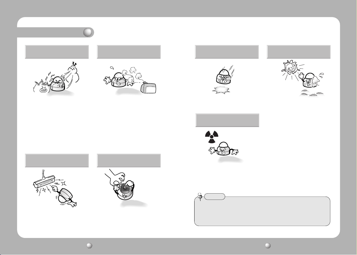
Do not install the camera in
extreme temperature conditions.
Only use the camera under conditions
where temperatures are between
-10˚C and +50˚C. Be especially careful
to provide ventilation when operating
under high temperatures.
Do not install the camera under
unstable lighting conditions.
Severe lighting change or flicker can
cause the camera to work improperly.
Do not install or use the camera in an
environment where the humidity is high.
It can cause the image quality to be
poor.
Do not touch the front lens of the
camera.
It is one of the most important parts
of the camera. Be careful not to be
stained by fingerprint.
Do not drop the camera or subject
them to physical shocks.
It can cause malfunctions to occur.
Never keep the camera face to
strong light directly.
It can damage the CCD.
Do not expose the camera to
radioactivity.
If it is exposed to radioactivity, For
heated CCD, it will be out of order.
Notes
• If the camera is exposed to spotlight or object reflecting strong light, smear or
blooming may occur.
• Please check that the power satisfies the normal specification before connecting
the camera.
COLOR CCD CAMERA User’s Manual
8
COLOR CCD CAMERA User’s Manual
9
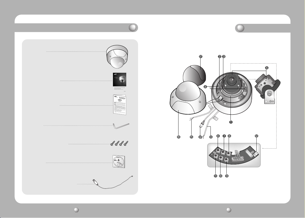
Components and Accessories
1. SVD-4300
2. Instruction Manual
3. Quick Install Guide
4. Wrench
5. Ø5 Tapping Screws 4EA
6. Template
Overview
7. Installation Video Output Cable
COLOR CCD CAMERA User’s Manual
10
COLOR CCD CAMERA User’s Manual
11
Overview
Connection
Pan Base
control panning angle of camera
Rotate Base Holding Screw
fix rotated position
Rotate Base
control rotating angle of camera
Pan Base Holding Screws (Color : Silver)
fix panned position
Auto Focus 10x Zoom Lens Module.
SET button
To access the main setup menu. Pressing the “SET” button locks the zoom control
functions of these buttons and prompts the main setup menu.
AF button
To activate auto focus just once.
UP (WIDE button)
To move the arrow indicator to up.(To widen the view : ZOOM OUT)
DOWN(TELE button)
To move the arrow indicator to down (To close in on a far object: ZOOM IN)
LEFT (F-NEAR button)
To move the arrow indicator to left. (To see a near object clearly)
RIGHT (F-FAR button)
To move the arrow indicator to right. (To see a far object clearly)
Video Output Terminal to Monitor
Power Input Jack
Video Output Jack
RS-485 Control Cable
The detailed description refers to p15
Dome Cover
Shield Case
Notes
• The zoom postion is saved after 5 seconds when you set zoom function.
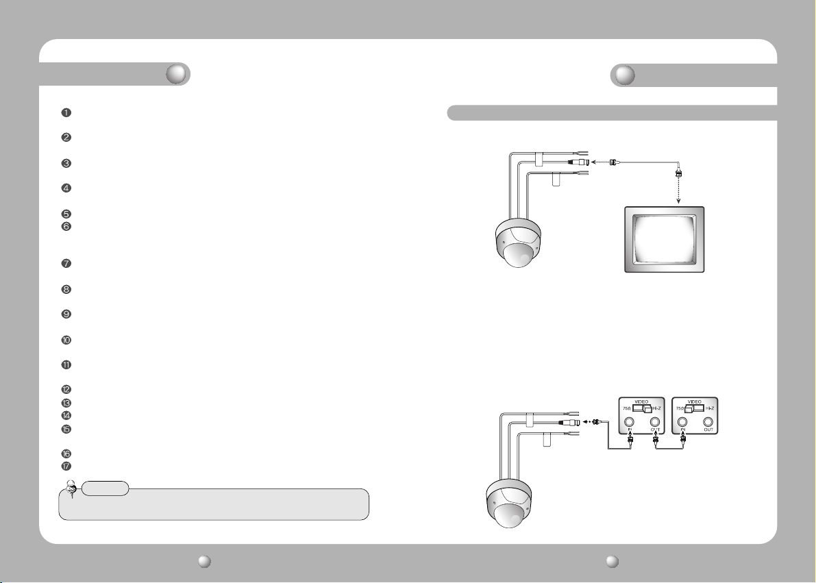
Connecting to Monitor
Connect the VIDEO-OUT jack to the VIDEO-IN jack of monitor.
CCTV Camera Monitor
• As the connecting method varies with the instruments, refer to the manual
supplied with the instrument.
• If necessary, you can connect the monitor to the REMOTE jack on the back of
your camera.
• Only connect the cable when the power is turned off.
• Set the 75Ω / Hi-Z selection switch as shown below if you have an intermediate
device.
CCTV Camera
Intermediate End monitor
COLOR CCD CAMERA User’s Manual
12
COLOR CCD CAMERA User’s Manual
13
Connection
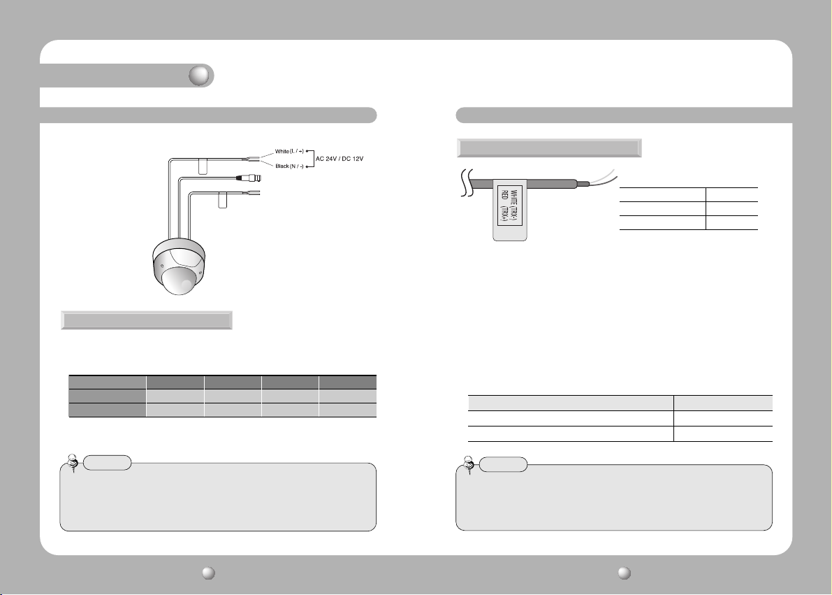
Connecting to Power
Use AC 24V / 300mA or DC 12V / 500mA power source.
For DC Power Type
• For DC power as the voltage drop according to the length of the cable in the
above table, a camera may malfunction if there is an excessively long cable run.
Resistance of copper wire [at 20C˚ (68˚F)]
Copper wire size (AWG)
Resistance ( Ω / m) 0.078 0.050 0.030 0.018
Voltage Drop (V/m) 0.028 0.018 0.011 0.006
* Voltage for camera operation: 12V DC ±10%
* Voltage drops in the above table are variable according to types of cable manufacturer.
Notes
• Be sure to connect power only after all the installation is complete.
• Note that AC or DC adaptor is not supplied with camera.
• Use the UL listed, class 2 power transformer of AC 24V adaptor.
• Ground should be connected to the GND terminal.
#24(0.22mm2) #22(0.33mm2) #20(0.52mm2) #18(0.83mm2)
RS-485 communication control
Connecting to RS-485 Control Cable
CONTROL CABLE SPEC
RED (TRX+) RS-485+
WHITE(TRX-) RS-485-
Using a RS-485 communication, it will be able to control the ZOOM/FOCUS and
OSD menu at the SAMSUNG TECHWIN System Controller or DVR.
(1) The case which it controls from the PC
Using a RS-485 converter, It connects to RS-485 control cable outside camera
and serial cable
EX) SERIAL PORT OF THE PC(COM1) — SERIAL CABLE -- RS-485 CONVERTER
-- RS-485 CONTROL CABLE
(2)The case which it controls from the DVR or System Controller
It connects the RS-485 control cable in the connection terminal of 485 control
boards which are connected with the DVR or System Controller.
485 CONTROL BOARD CONNECTION TERMINAL RS-485 CONTROL CABLE
(+)CONNECTION TERMINAL RED (TRX+)
(-)CONNECTION TERMINAL WHITE(TRX-)
Notes
• When you construct external control systems for a camera control, please use to
the SAMSUNG TECHWIN PROTOCOL or PELCO-D PROTOCOL.
• When you connecting to RS-485 control cable, please peel off the outer skin inside
the RS-485 control cable.
COLOR CCD CAMERA User’s Manual
14
COLOR CCD CAMERA User’s Manual
15
 Loading...