

Samsung STP-102S, STP-102P User Manual
DATE: July. 2001
MANUAL REVISION 2.0
STP-102S / STP-102P
Operator's Manual
Warning - U.S
This equipment has been tested and found to comply with the limits for a Class A
digital device pursuant to Part 15 of the FCC Rules. These limits are designed to
provide reasonable protection against harmful interface when the equipment is
operated in a commercial environment. This equipment generates uses, and can
radiate radio frequency energy and, if not installed and uses in accordance with
the instruction manual, may cause harmful interference to radio communications.
Operation of this equipment in a residential area is likely to cause harmful
interference in which case the user will be required to correct the interference at
his own expense.
Notice - Canada
This Apparatus complies with class "A" limits for radio interference as specified in
the Canadian department of communications radio interference regulations.
Introduction
The STP-102S and STP-102P Roll Printer is designed for use with electric instruments
such as system ECR, POS, banking equipment peripheral equipment, etc
.
POWER
ERROR
ELECTRO- MECHANICS
FEED
The main features of the printer are as follows:
1. High speed printing
2. Low noise thermal printing.
3. RS-232 serial interface (STP-102S). Parallel interface (STP-102P).
4. The data buffer allows the unit to receive print data even during printing.
5. Different print densities can be selected by DIP switches.
ON LINE
Please be sure to read the instruction in this manual carefully before using your
new STP-102S and STP-102P.
NOTE
The socket-outlet shall be near the equipment and it shall be easy
accessible.
TEL : 82-31-210-5620
FAX : 82-31-210-5589
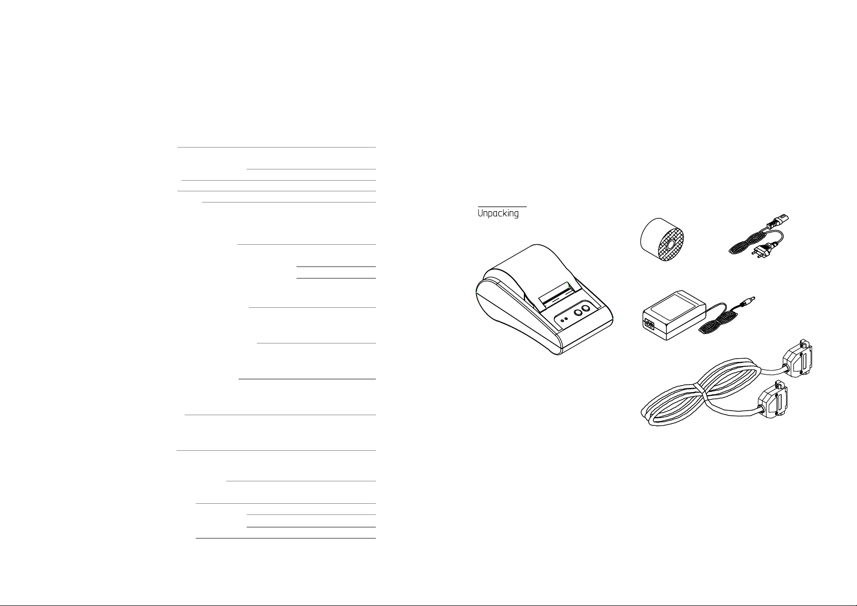
Table of Contents
Chapter 1. Unpacking
1-1. Checking the contents of the Printer.
Chapter 1. Unpacking
1-1. Checking the contents of the Printer
1-2. Locating the Printer
1-3. Printer Part names
1-4. Operating Control Panel
Chapter 2. Connecting the cable
2-1. Connecting the AC adapter to your printer
2-2. Connecting the Printer to your computer 8
4
4
4
5
6
7
7
Chapter 3. Installing the Paper Roll 10
Chapter 4. Setting the DIP Switching 11
Chapter 5. Running the Self Test 13
Chapter 6. Code Table 14
The items illustrated below are included with your printer.
If any items are damaged or missing, please contact your
dealer for assistance.
Roll paper
Printer
Adaptor
Power cord
Cable
Chapter 7. Functions 21
Chapter 8. Control Commands 23
APPENDIX A - Connectors
- Serial Type (STP-102S)
- Parallel Type (STP-102P)
APPENDIX B - Specification
34
34
34
35
1-2. Locating the Printer.
Avoid location in direct sunlight or excessive heat.
Avoid or storing the printer in the place subject to excessive moisture.
Do not use or store, horizontal surface for the printer. Avoid places subject to
intense vibration or shock.
Make sure that there is enough space around the printer so that it can be used easily.
3
4
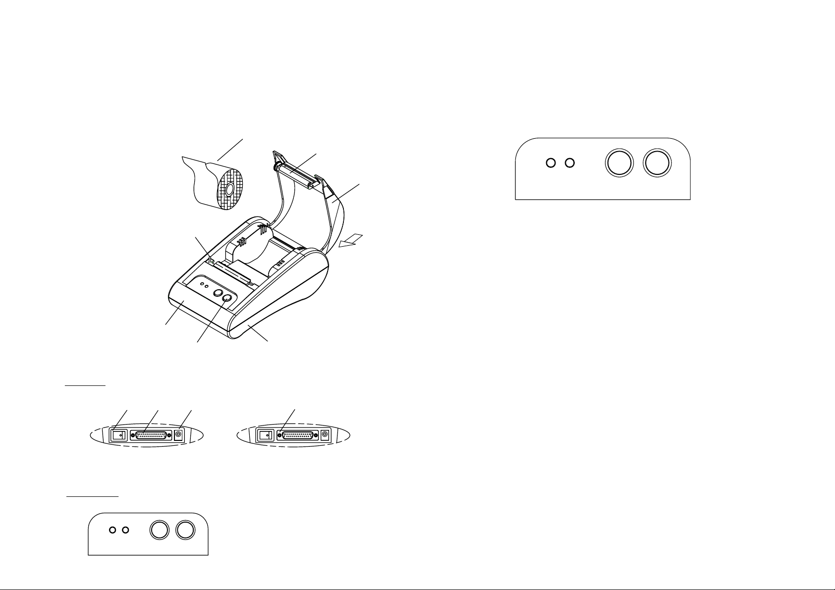
1-3. Printer Part Names
1-4. Operating Control Panel
(1) Cover top
(2) Case top
(3) Case bottom
(4) Control panel
(5) Roller
(6) Power switch
(7) Interface connector (male)
(8) DC Jack
(9) Interface connector (female)
(10) Roll paper
(11) Detector switch
Rear View
(6) (7) (8)
(2)
(10)
(11)
(4) (3)
(9)
(5)
(1)
Rear View
The control panel has two buttons and two lights.
POWER ERROR FEED ON LINE
Buttons
The control panel buttons perform paper feeding and on line function.
ON LINE
Press the ON LINE button to ready to receive data from the computer.
FEED
Press the FEED button once to advance paper one line. You can also press the FEED
button continuously to feed paper continuously.
Feed button is valid when ON LINE button is off.
Indicator lights
The control panel lights provide information on printer conditions.
POWER(green)
The POWER light is on when the printer power is on.
Control Panel
POWER ERROR
STP-102S STP-102P
FEED ON LINE
ERROR(red)
1) The error LED blinks fast when paper is out.
2) The error LED blinks when the Near End Sensor triggered.
5
6
Chapter 2. Connecting the Cable
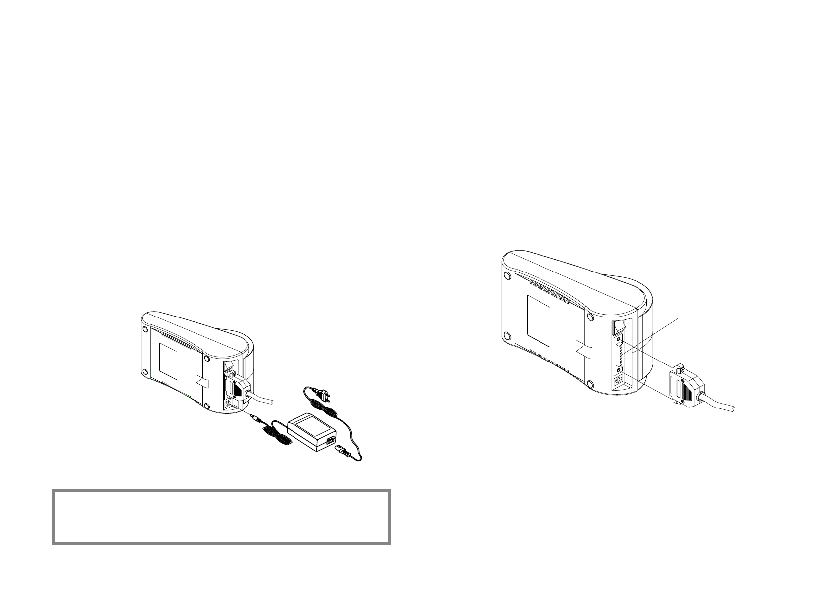
2-1. Connecting the AC adapter to your printer
When the printer is used, use te optional AC adapter, AP-1611-UV for your printer.
Using an incorrect power supply may cause fire or electrical.
When connecting or disconnecting the power supply from the printer, make sure that
the power supply is not plugged into an electrical outlet ; otherwise you may damage
the power supply or the printer
1. Make sure that the printer's power switch is turned off, and that the power supply's
power cord is unplugged from the electrical outlet.
2. Check the label on the power supply to make sure that the requird voltage matches
that of your electrical outlet.
3. Plug the power supply's DC cable connector into the printer's power connector as
shown below.
STP-102S / STP-102P
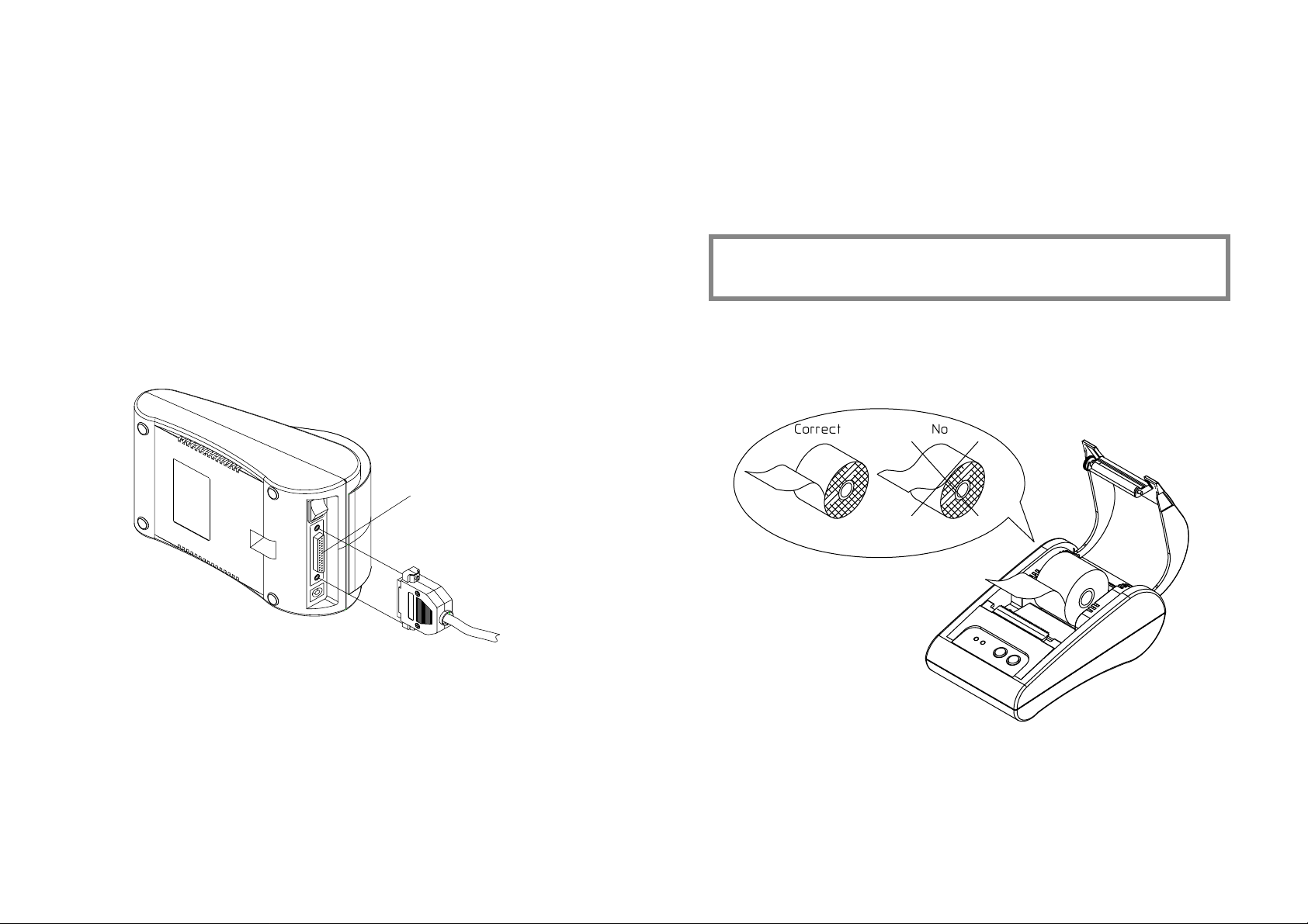
2-2. Connecting the printer to your Computer
STP-102S
You need an appropriate serial interface cable to connect your computer to the
printer's built-in interface.
1. Make sure that both the printer and computer are turned off :
then plug the cable connector securely into the printer's interface connector.
2. Tighten the screws on both sides of the cable connector.
25 Pin Male Type
4. Plug the AC adapter's power cord into an electrical outlet.
NOTE
To remove the DC cable connector grasp the connector at the arrow and
pull it straight out. Make sure that the main unit's power cord is unplugged
before you disconnect the DC cable connector.
3. Plug the other end of the cable into the computer
7
8
Chapter 3. Installing the Paper Roll
2-2. Connecting the printer to your Computer
STP-102P
You need an appropriate serial interface cable to connect your computer to the
printer's built-in interface.
1. Make sure that both the printer and computer are turned off :
then plug the cable connector securely into the printer's interface connector.
2. Tighten the screws on both sides of the cable connector.
25 Pin Female Type
Use a paper roll that matches the specifications.
NOTE
The printer must be turned off before installing the paper roll.
1. Open the printer cover and remove the used paper roll core if there is one.
2. Insert the paper roll as shown below.
3. Plug the other end of the cable into the computer
3. Pull out the paper roll until the paper comes out from the top of the printer. Then
close the printer cover.
4. Turn on the Printer.
9
10
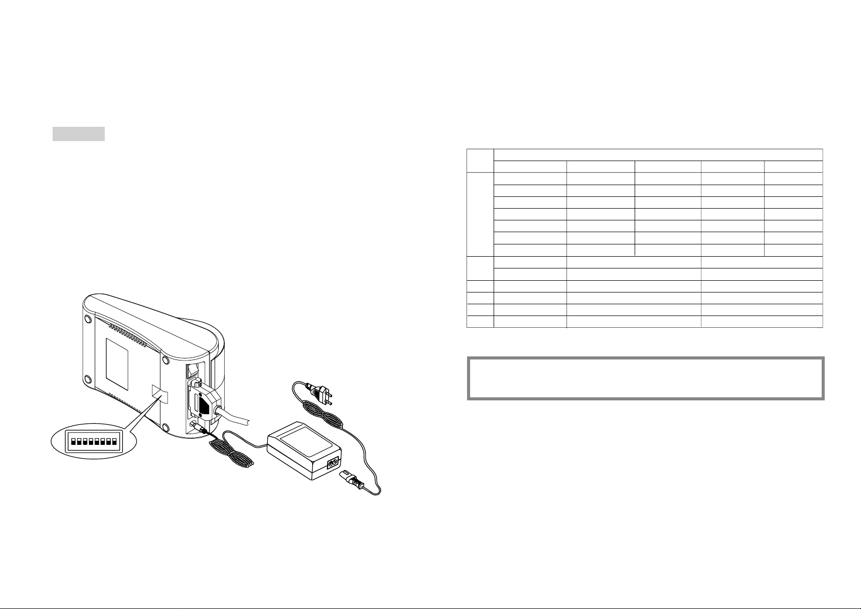
Chapter 4. Setting the DIP Switches
CAUTION
DIP switch functions
Turn off the printer while setting the DIP switch to prevent an electrical short, which can
damage the printer.
You can change your interface and printer density settings by changing the DIP switch
setting.
1. Make sure the printer is turned off.
2. There are a switch. Notice that ON is marked on each set of switches.
Use tweezers or another narrow tool to move the switches.
1
No.
1
2
3
4
5
6
7
8
Level
1
2
3
4
5
6
7
Function
Density
Handshaking
Reserved
Language
Reserved
BPS
2400
4800
9600
19200
38400
57600
115200
Dip Switch
D/W1
ON
OFF
OFF
ON
ON
OFF
ON
ON OFF
Dark
Xon/Xoff
Engish
-
NOTE
Dip Switch 7 must be always set to ON condition.
D/W2
OFF
ON
OFF
OFF
ON
ON
ON
Normal
DTR/DSR
Korean
-
S/W3
OFF
OFF
ON
ON
OFF
ON
ON
3. Use the following tables to set the DIP switches.
11 12
 Loading...