

Samsung STH-N271 Service Manual
SERVICE
SINGLE BAND Mobile
Cellular Phone
STH-N271
Manual
SINGLE BAND Mobile Cellular Phone CONTENTS
1. Specification
2. Trouble Shooting
3. Test Procedure
4. Function of All Active Devices
5. Frequency Synthesizer Circuit
and Spurious Radiation
Suppression Circuit
6. Easy NAM Programming
7. Electrical Parts List
8. Exploded Views and Parts List
9. Block Diagram
10. PCB Diagrams
11. Circuit Description &
Circuit Diagrams
3
2
6
5
9
4
8
7

©Samsung Electronics Co.,Ltd. August. 2001
Pinted in Korea.
Code No.: GH68-02202A
BASIC.
ELECTRONICS
1. STH-N271 SPECIFICATION (REF TIA/EIA/IS-137-A-1)
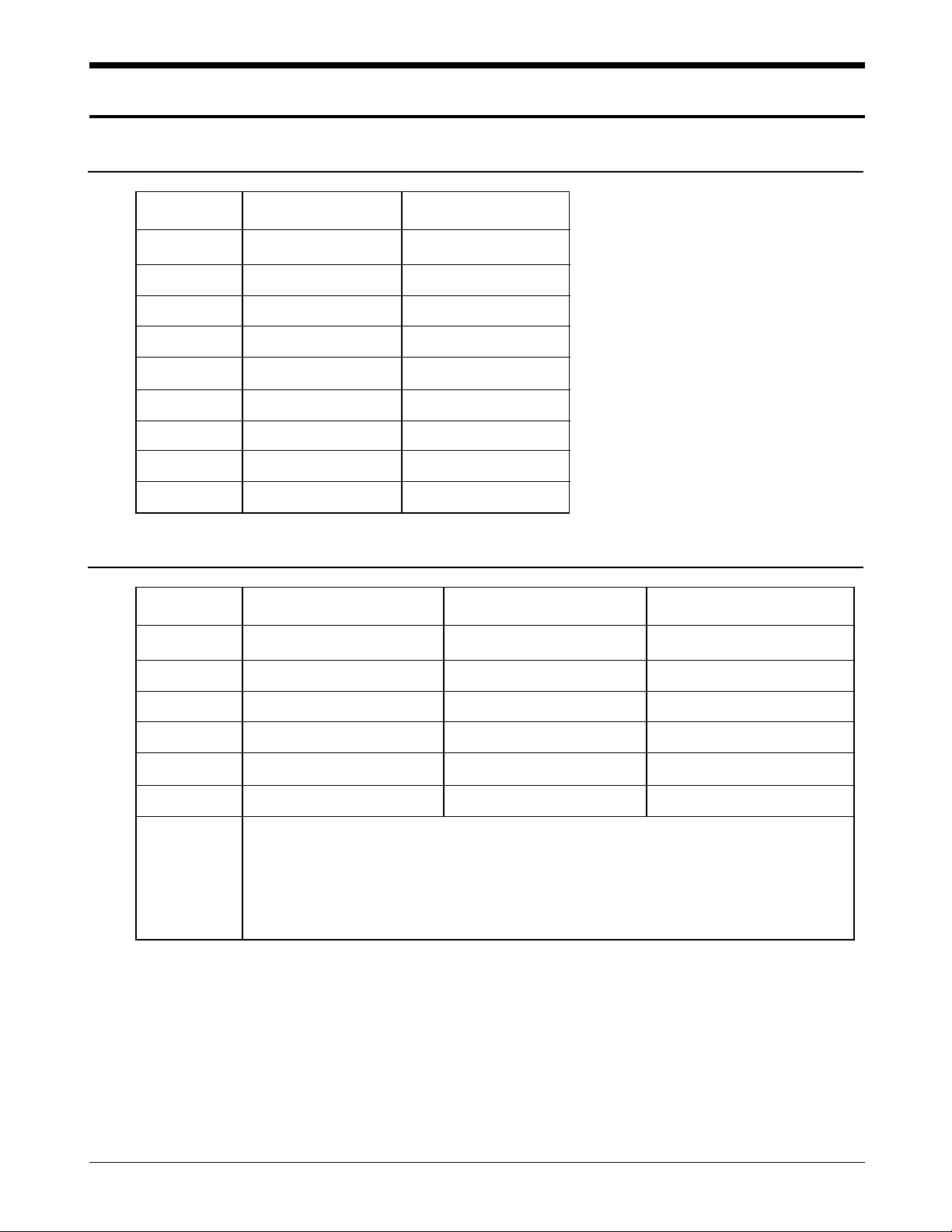
1. Confirmation of Power level (Class IV)
SAMSUNG Proprietary-Contents may change without notice
1-1
Level Analog(dBm) Digital(dBm)
0,1,2 26.5 26.5
323 23
420 20
516 16
612 12
78 8
8- 3
9- -2
10 - -7
2. Channel Numbering and Frequency
System Channel Number Transmitter Receiver
(Not used) 990 CH 824.01 MHz 869.01 MHz
A” 991 CH ~ 1023 CH 824.04 ~ 825.00 MHz 869.04 ~ 870.00 MHz
A 1 CH ~ 333 CH 825.03 ~ 834.99 MHz 870.03 ~ 879.99 MHz
B 334 CH ~ 666 CH 835.02 ~ 844.98 MHz 880.02 ~ 889.98 MHz
A’ 667 CH ~ 716 CH 845.01 ~ 846.48 MHz 890.01 ~891.48 MHz
B’ 717 CH ~ 799 CH 846.51 ~ 848.97 MHz 891.51 ~ 893.97 MHz
#. Transmitter : 1 < N < 799 : 0.03N + 825.00 MHz
990 < N < 1023 : 0.03(N-1023) + 825.00 MHz
#. Receiver : 1 < N < 799 : 0.03N + 870.00 MHz
990 < N < 1023 : 0.03(N-1023) + 870.00 MHz
SAMSUNG Proprietary-Contents may change without notice
1-2
STH-N271 Specification
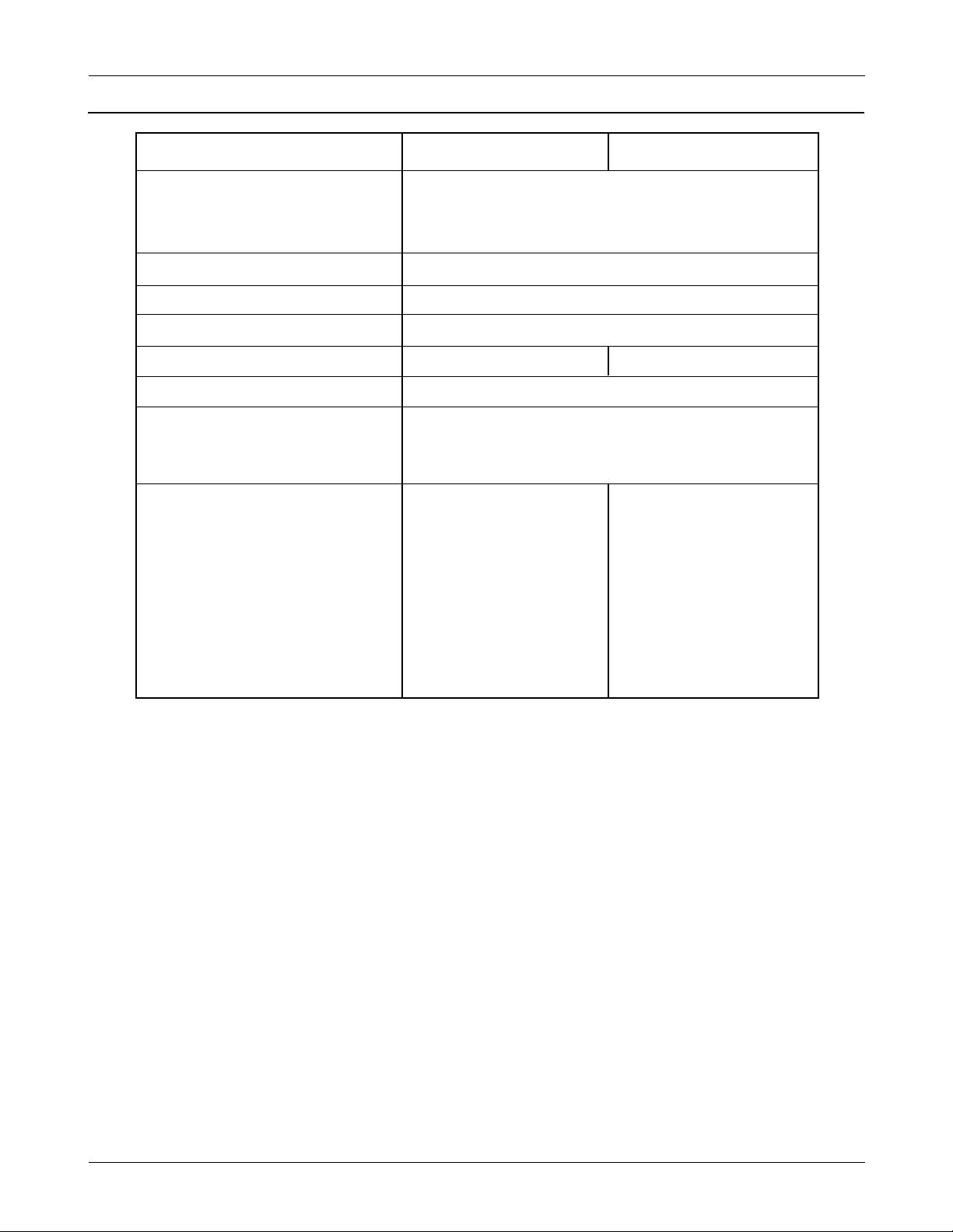
3. General
Item Analog mode Digital mode
Frequency Range
Transmitter 824.04 ~ 848.97 MHz
Receiver 869.04 ~ 893.97 MHz
Channel Space 30 kHz
Numbers of Channel 1024
Duplexer Space 45 MHz
Frequency Stability ± 2.5 ppm ±200 Hz
Operating Temperature - 30 oC ~ +60oC
Size and Weight
Including 900 mAh battery 108 (H) x 42 (W) x 17.2 (D) : 93 g
Including 1200 mAh battery 108 (H) x 42 (W) x 18.7 (D) : 100 g
Operating Time
Standby time
Including 900 mAh battery 35 ~ 45 hr 130 ~ 230 hr
Including 1200 mAh battery 45 ~ 55 hr 190 ~ 300 hr
Talk time
Including 900 mAh battery 60 ~ 90 min 2 ~ 3 hr
Including 1200 mAh battery 80 ~ 120 min 2.5 ~ 4.5 hr
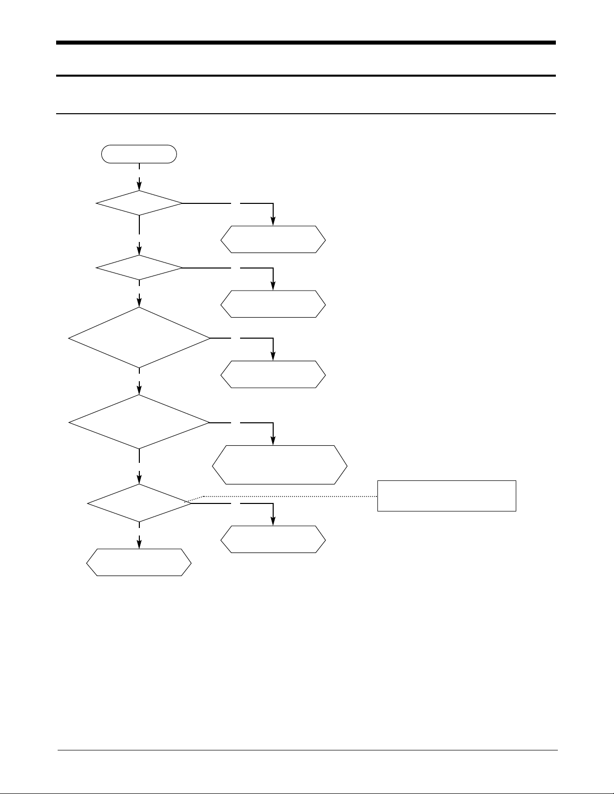
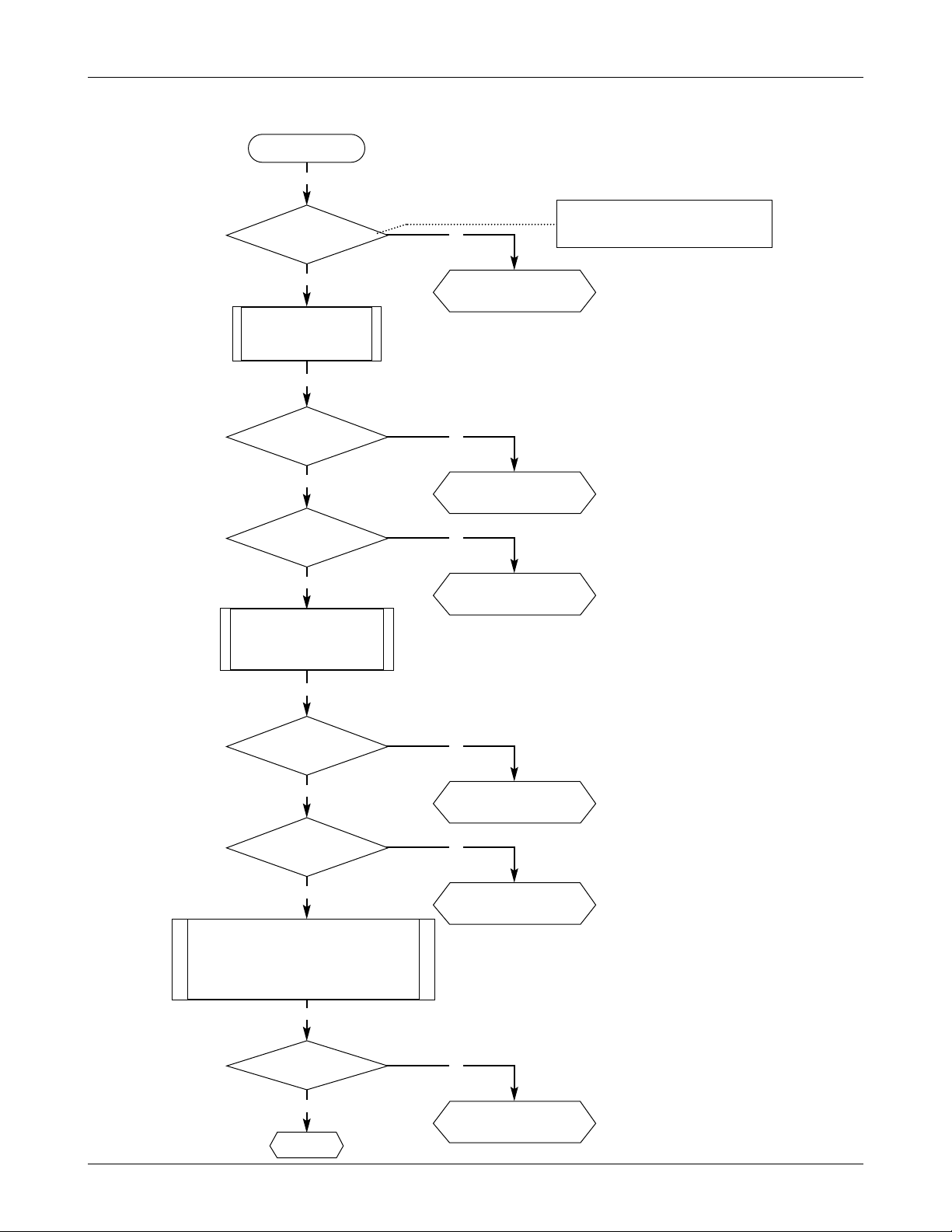
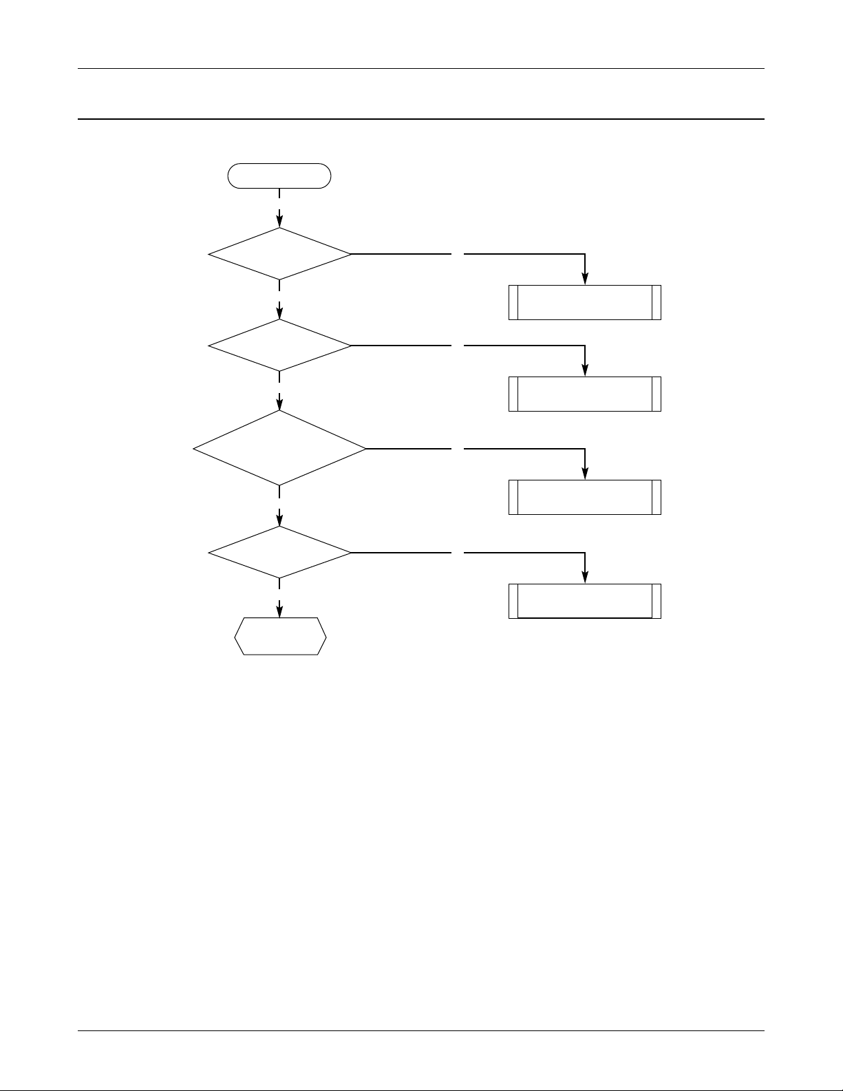
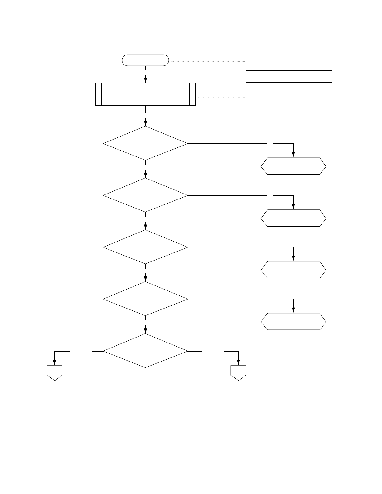
N
Need to check
Q107, Q106
N
Replace dome S/W
N
Need to check
Q107, Q106
N
Need to replace
Memory(U202)
N
Need to check neighbor part
Need to check OSC320,
Y201 & neighbor part
SAMSUNG Proprietary-Contents may change without notice
2-1
2. STH-N271 Trouble Shooting
1. Baseband Section
1-1. Program No Running
Press END Key
Y
Y
Y
Y
Y
Y
ON_SW=H
VBAT>3.2V
VCTCXO_IN=14.4MHz
32K_XIN=32.768 kHZ
Memory (U202)
control signal OK?
VCC=3.0V
V_VCTCXO=3.0V
RST=3.0V
IVCC=2.2V
BOOT=H
Program Running
VCC, ADD(0:21), DATA(0:15),
FLASH_CS, SRAM_CS, UBE,
MEMOEB, MEMWEB
SAMSUNG Proprietary-Contents may change without notice
2-2
STH-N271
Trouble Shooting
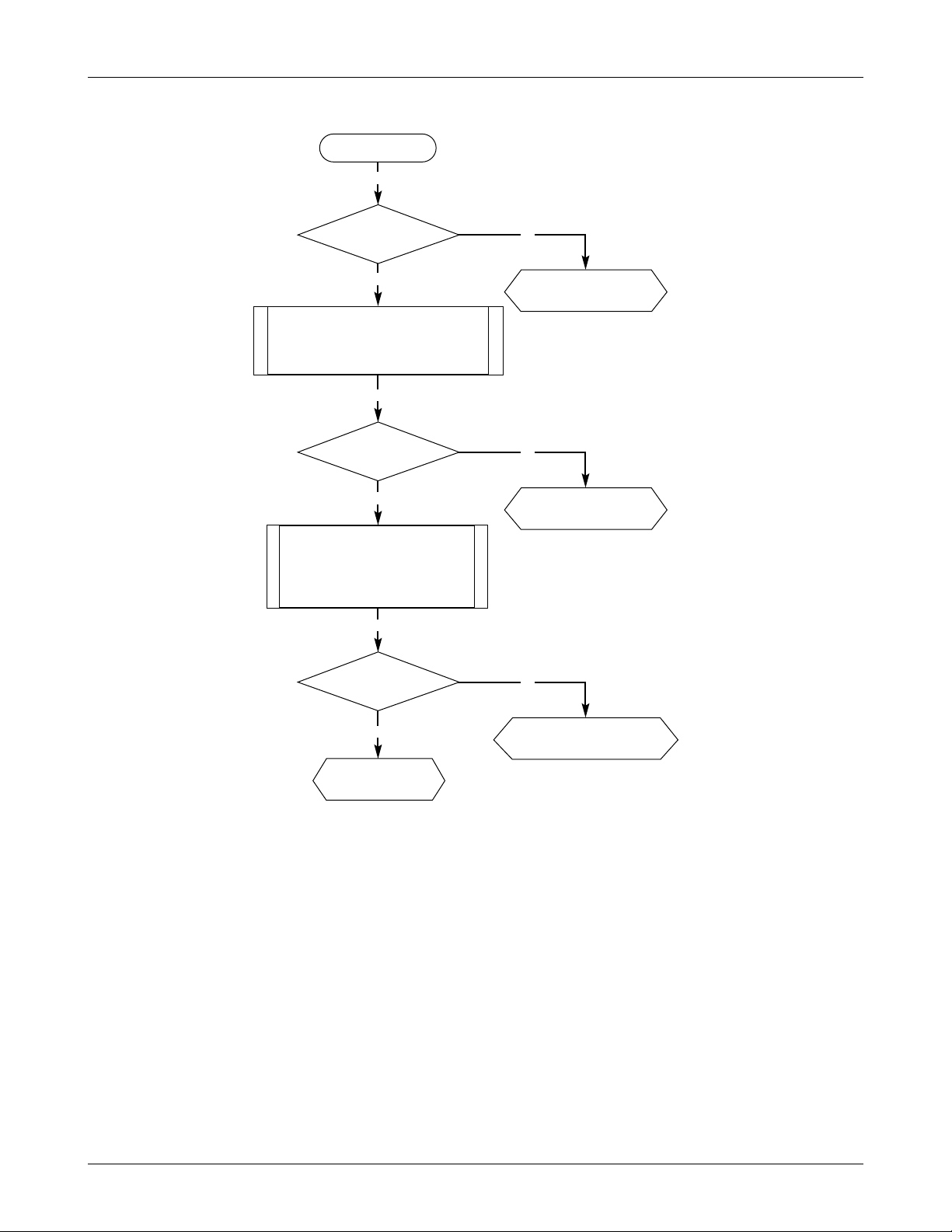
N
Need to check
U103 & neighbor part
N
Need to check
R126, C148
1-2. Abnormal LCD display ,EL Back Light, Vibrator & Speaker Operation
START
Y
Y
LCD Control
Signal OK?
Y
Y
EL_EN=H
N
Need to check U104
& neighbor Part
Y
EL Back light
OK?
VCC, ADD(2), DATA(0:7),
DISPLAY_CS, RST
LCD Display Running
Send Command EL
enable(Test mode:176)
N
Need to check
R216, U205, D202
Y
Y
VIBRATOR=H
N
Need to check CN202
Y
Vibrator Run
OK?
LCD Display Running
EL Back lingt Running
Send Command Vibrator
enable(Test mode:180)
N
Need to check SPK101
& neighbor part
Y
Y
REC20+,- Signal
OK?
LCD EL Vibrator OK Send Command
Main Audio Receiver Path ON
(Test mode:031, 131, 134, 185)
Good
SAMSUNG Proprietary-Contents may change without notice
2-3
STH-N271
Trouble Shooting
N
Need to check Dome
S/W & U103
N
Need to check MIC101
& neighbor part
1-3. Abnormal Key, Mic, LED’S operation
Press Keys
Y
Y
Key Dispaly
OK?
Y
Key Display Good
Send Command Main Audio Path ON
(Test mode:031, 131, 136, 187)
Talking Voice at MIC+
N
Need to check
D210, D211, Q204, Q206
Y
Y
Y
LED Operation
OK?
Key Display Good
Mic Path Good
Send Command ALT_LED_ON
Send Command SVC_LED_ON
Send Command LED_ON
(Test mode:178)
Audio signal output
at Speaker?
GOOD
SAMSUNG Proprietary-Contents may change without notice
2-4
STH-N271
Trouble Shooting
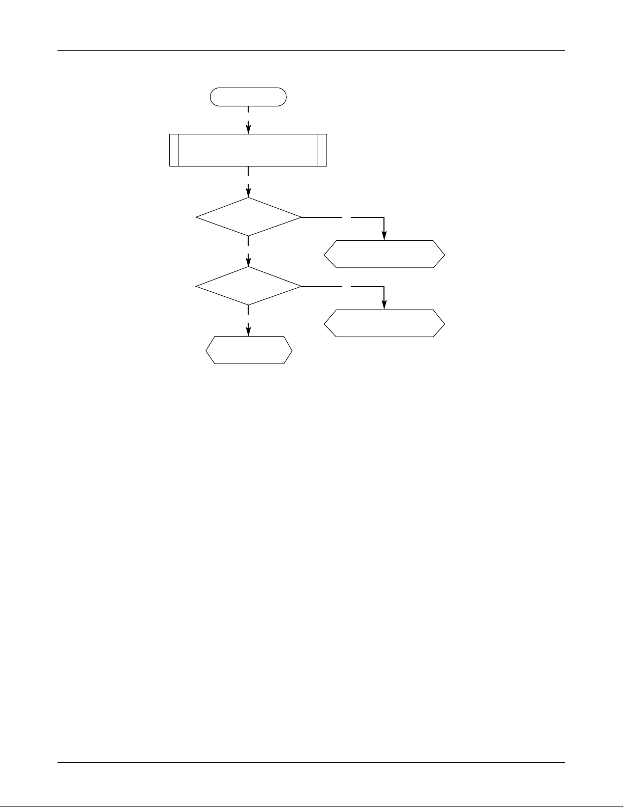
1-4. Abnormal Buzzer Operation
START
Y
N
Need to check
U204, D201, CN202
Y
Y
Ringer Signal
OK?
Send Command Ringer Path ON
(Test mode:183)
N
Replace CN202
Y
Buzzer Sound Output
OK?
Buzzer Operation
Good
SAMSUNG Proprietary-Contents may change without notice
2-5
STH-N271
Trouble Shooting
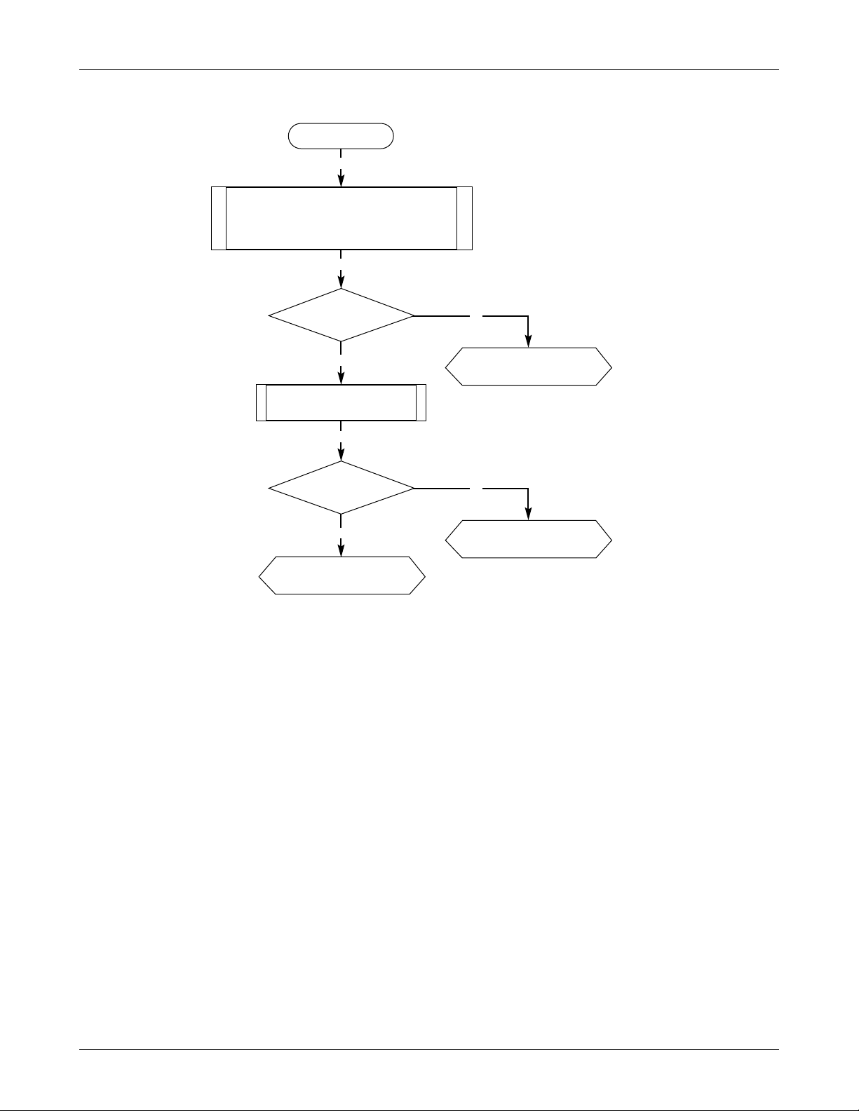
1-5. Abnormal external Ear_Mic Jack operation
START
Y
N
Need to check Q101,
CN101 & neighbor parts
Y
Y
HEADSET_SENSE=H
Hock Up Ear_Mic Phone in the Jack(CN101)
Send Command MIC_BIAS_EN enable Send
Command AMP_EN enable
Audio set Path=HS
(Test mode:187)
N
Need to check Q102,
CN101 & neighbor parts
Y
Y
SEND_END=H
Press Button on the Ear-Jack
Ear_Mic phone
Operation Good
SAMSUNG Proprietary-Contents may change without notice
2-6
STH-N271
Trouble Shooting
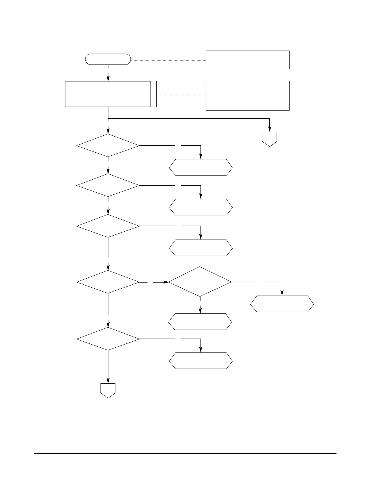
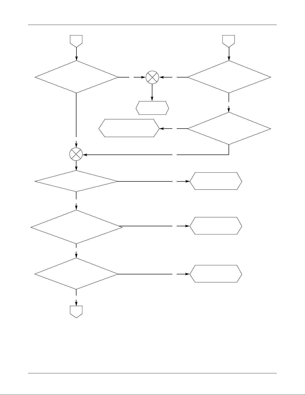
2. RF Section
2-1. Call processing and Online Test
N
DONE
START
Y
Y
Normal SVC?
Check RX path
N
Y
Set up Call OK?
Check TX path
N
Y
Measure SINAD/BER
Good?
Check RX path
N
Y
Measure
Tx Power Good?
Check TX path
SAMSUNG Proprietary-Contents may change without notice
2-7
STH-N271
Trouble Shooting
1
N
Need to check
U302
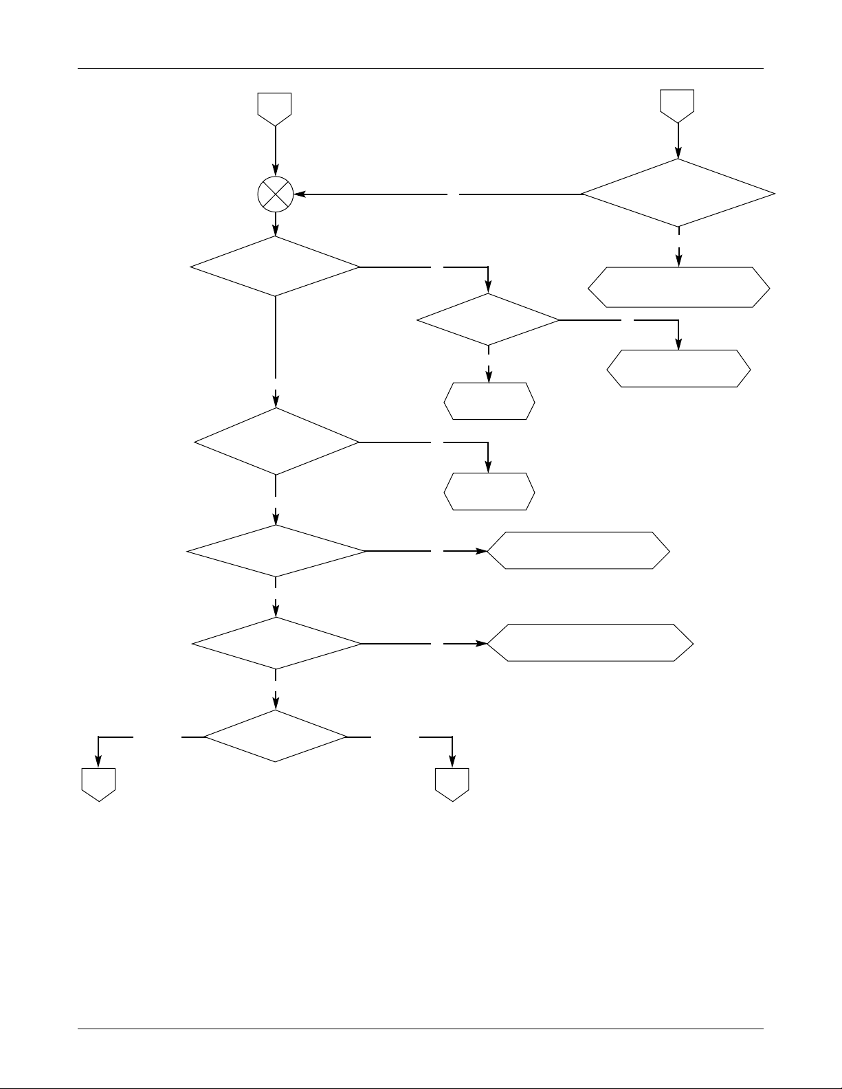
2-2. Receiver Section (Offline test)
Y
Y
Y
Y
F305 input=-55dBm
N
Need to check
F305
N
Need to check
U105, U106, U107
F305 output=-49dBm
Y
N
Need to check
F306
U301_8=-53dBm
N
Need to check
F304 & neighbor parts
Y
RF_BAND=L, RX_BAT=H
PLL_ON=H, PON_LC=H
VCTCXO_PC=H, IF_ON=H
PON_VRF3=H
set up 8920B basestation for RX test
Set Base station RX Lev=-50 dBm
Send Command RX path ON
Send Command channel selecton
(Test mode:134, 131)
START
N
Y
V_LNA_CELL=H
U107_1=H
U105_1=H
Need to check
U301 & neighbor parts
F304 input=-33dBm
2
U304_45=-33dBm
SAMSUNG Proprietary-Contents may change without notice
2-8
STH-N271
Trouble Shooting
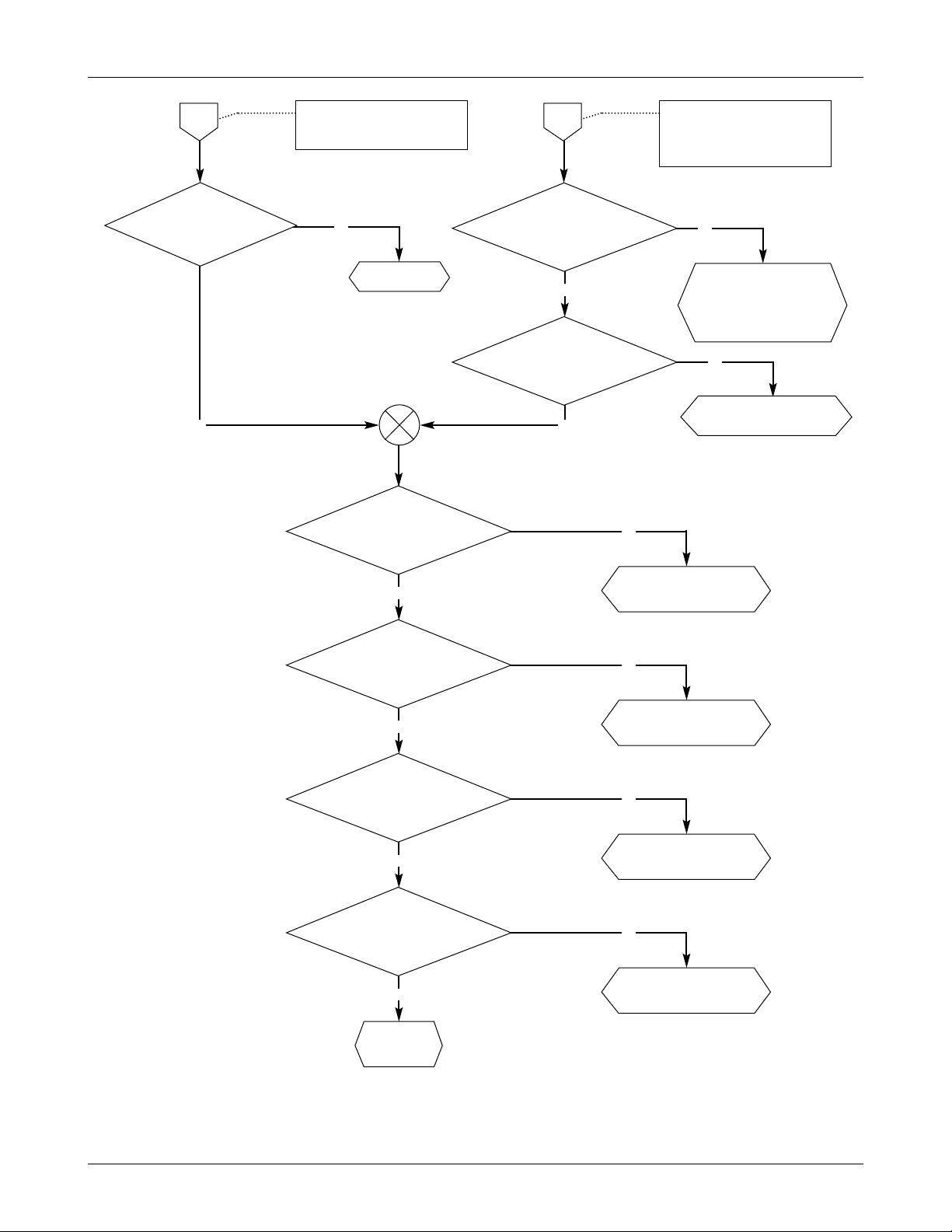
2
N
N
AMPSTDMA
N
Replace U304
Replace
F302
Need to check OSC301,
neighbor parts & U304_1,2,3
Need to check
U105 & neighbor parts
N
Y
Y
Y
Y
Y
RF loal check
U304_48 Lev=-6dBm
Freq=adjusted freq?
1
U304_41 Lev=-23dBm
Freq=130.05MHz
U304_34 Lev=-33dBm
Freq=130.05MHz
N
Need to check
U304, L303, C308, L301, C307
U304_37 Lev=-1dBm
Freq=450kHz
Y
N
Replace F301 or
Need to check R302, R304, C301
U304_25 Lev=-7dBm
Freq=450kHz
MODE
U304_40, 42=3.0V
43
SAMSUNG Proprietary-Contents may change without notice
2-9
STH-N271
Trouble Shooting
N
Replace U304
Case TDMA mode:
setup basestation for RX test
Amplitude:-50dBm
3
U304_9, 19, 11, 12
measure I/Q
Quarature wave
N
Need to check U304 &
Quad LC Tank circuit
(L310, C328, C330,
C329, R320)
PON_LD=H
Case AMPS mode:
setup basestation for RX test
Audio Freq gen : 1004Hz
FM deviation : 2.9kHz
4
Y Y
Y
U304_16 DEMOD
(sinusoidal wave)
Vp-p=24mV
Freq=1004Hz
N
Need to check U304 &
R327, R323, C353, C107
U101_52 DEMOD
(sinusoidal wave)
MAX Vp-p=1.4V
Freq=1004Hz
N
Replace U203
Y
U101_40 BBCLK=
6.2208MHz or 4.96NHz or
5.12MHz
N
Replace U203
Y
U101_32RX_CLK=
BBCLK/2 or
BBCLK/8
N
Replace U203
Y
U101_31 RX_SYNC=
BBCLK/32 or
BBCLK/128
N
Replace U203
Y
U101_31 RX_DATA=
serial data
DONE
SAMSUNG Proprietary-Contents may change without notice
2-10
STH-N271
Trouble Shooting
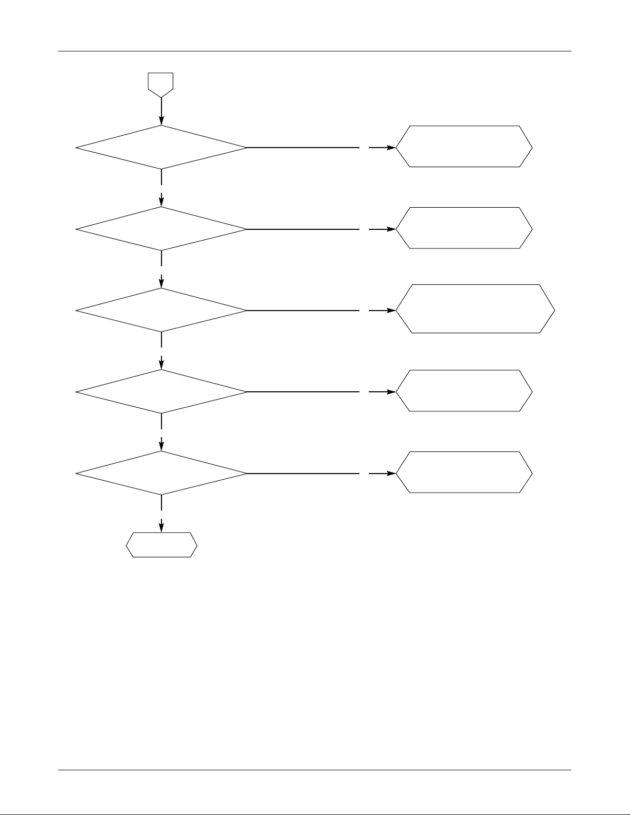
N
Replace U203
N
Replace U203
N
Replace U203
N
Replace U203
2-3.Transmitter Section (Offline test)
Y
Y
Y
U101_40 BBCLK=
6.2208MHz or 4.096MHz
or5.12MHz
Y
U101_34 TX_CLK=
BBCLK/32 or BBCLK/8
Y
U101_33 TX_SYNC=
BBCLK/512 or BBCLK/128
Y
U101_33 TX_DATA=
serial data
RF_BAND=L, TX_BAT=H
PLL_ON=H, VCYCXO_PC=H
IF_ON=H, PON_TX=H
PON_VRF3=H
setup 8920B as basestaion for
TX test audio signal?
Send command TX path ON
Send Command channel selection
(Test mode:136, 131)
START
AMPSTDMA
2 1
MODE
SAMSUNG Proprietary-Contents may change without notice
2-11
STH-N271
Trouble Shooting
1
3
Replace U101
Y
Y
Need to check
V_RF2=3.0V or
Replace U304
2
Y
U304_59(RF OUT)
Fc=Local_freq + 175.05
U101_61, 60, 58, 57
TX I/Q Quarature signal
AC Lev Vp_p=0.4V
DC bias Lev=1.5V
U101_63 MOD
(sinusoidal wave)
MAX Vp-p=1.4V
Freq=1004Hz
OSC303_1
(FM modulation out)
Freq=175.05MHz
Audio Freq=1004Hz
Need to check
OSC303,
V_IF_VCO=3.0V
NY
N
N
Y
Need to check
U304_66 or
Replace U304
U304_59(RF OUT)
measure Level
Send command PA_CNT
(Test mode:132)
Level is adjustable?
N
Y
Replace F310
U304_59(RF OUT)
Fc=Local_freq + 175.05
N
Y
SAMSUNG Proprietary-Contents may change without notice
2-12
STH-N271
Trouble Shooting
3
Y
Need to check
V_DRV_CELL=3.0V,
neighbor part or
Replace U307
U307 Gain
around 27dB
N
Y
Replace F309
F309 Insertion loss
around 3dB
N
Y
Need to check
V_PA_BAIS_CELL(U305_5,6,7)=3.0V
VBATT(U305_14,15,16)=3.2~1V
or Replace U305
U305 Gain
around 30dB
N
Y
Need to check
F313 & neighbor parts
F306_1 around same power
with U305 output
N
Y
Need to check
F313 & neighbor parts
F306 insertion loss
under 3dB
N
DONE

3. STH-N271 TEST PROCEDURE
1. List of Equipment
•
8920B TDMA M/S TEST SET (HP CARD, modified by Samsung )
• SIGNAL GENERATOR (2 SETS)
• SPECTRUM ANALZER
• DEVICE UNDER TEST (STH-N271)
• TEST INTERFACE ADAPTER
•
COMBINNER
• DC POWER SUPPLY
• PC
• Cables (RF CABLE, DATA CABLE, SERIAL CABLE, etc.)
SAMSUNG Proprietary-Contents may change without notice
3-1
SAMSUNG Proprietary-Contents may change without notice
3-2
STH-N271 Test Procedure
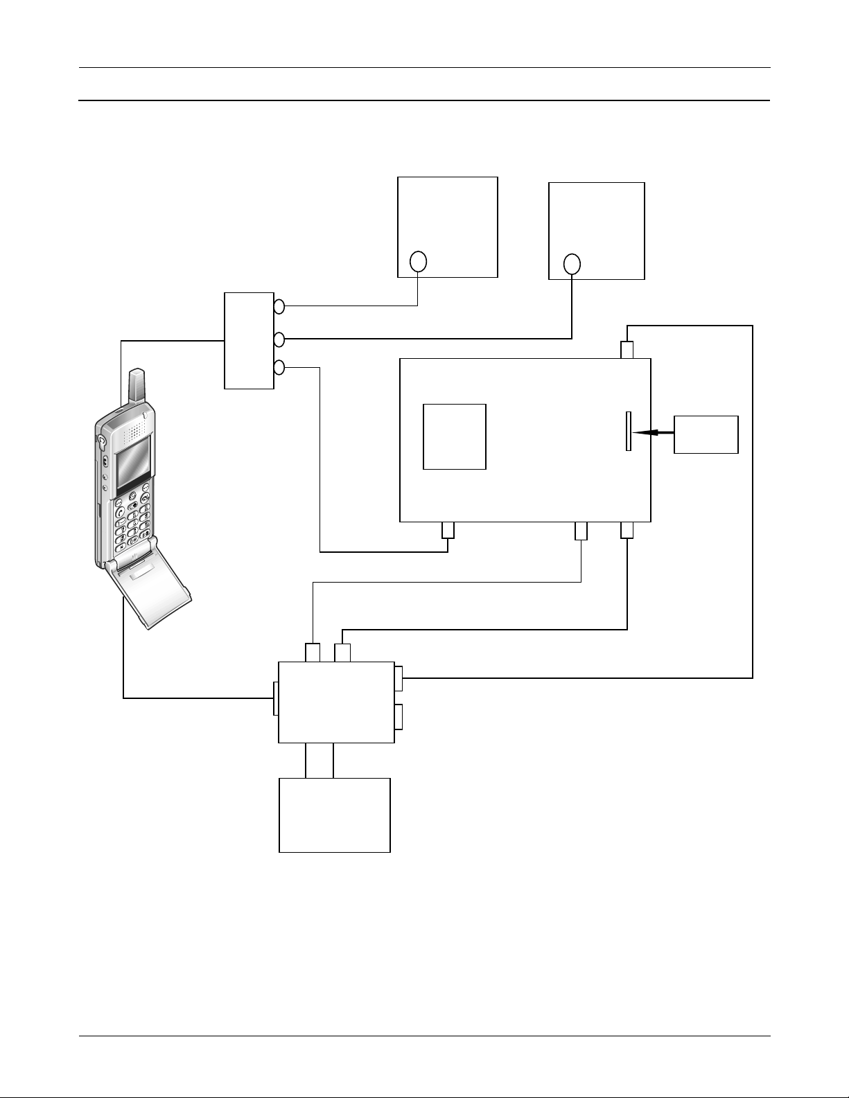
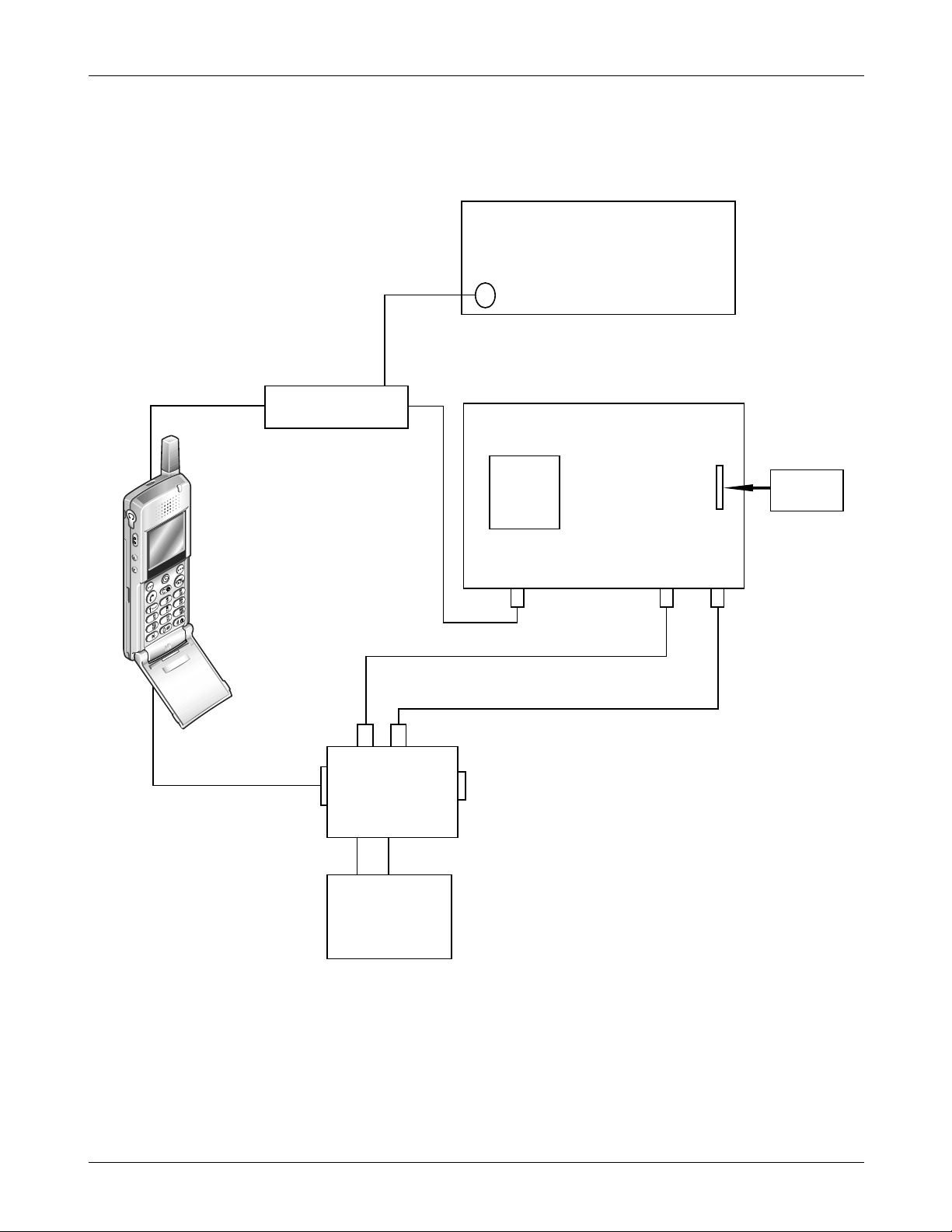
2. Configuration of Test
2-1. Test Configration-1
2
3
6
4
5
8
7
9
RF cable
DUT
Data cable
TEST I/F
ADAPTER
+ 3.8 V
A-OUT
TO PC TO HP
A-IN
DC P/S
4 pin cable
RF IN/OUT
A-OUT
A-IN
8920B TDMA M/S TEST SET
HP CARD
serial port
Signal
GEN2
Signal
GEN1
combinner
SAMSUNG Proprietary-Contents may change without notice
3-3
STH-N271 Test Procedure
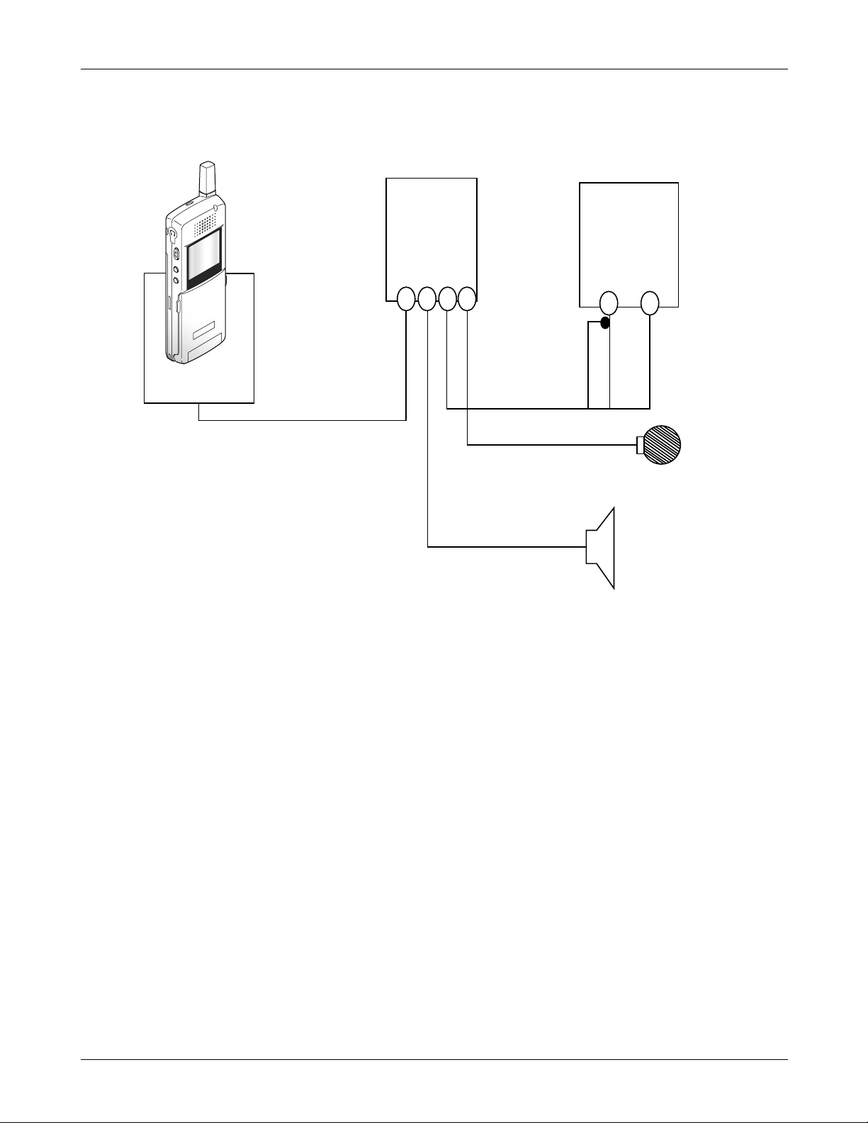
2-2. Test Configration-2
2
3
6
4
5
8
7
9
RF cable
coupler
DUT
Data cable
TEST I/F
ADAPTER
DC P/S
+ 3.8 V
A-OUT A-IN
RF IN/OUT A-OUT A-IN
HP CARD
8920B TDMA M/S TEST SET
Spectrum Analyzer
SAMSUNG Proprietary-Contents may change without notice
3-4
STH-N271 Test Procedure
2-3. Test Configration-3 (Hands Free Kit)
Ignition
Cable
DUT
Cradle
Data cable
Hands Free
Kit BOX
Power cable
DC Power
Supply
+13.7 V
Hands Free Mic
Hands Free Speaker
SAMSUNG Proprietary-Contents may change without notice
3-5
STH-N271 Test Procedure
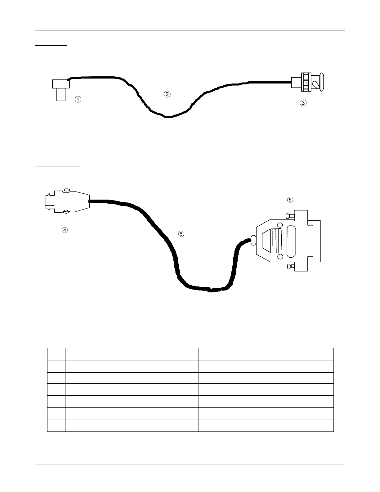
RF CABLE
DATA CABNLE
Table 3-Test Cable description
NAME DESCRIPTION
1 RF CONNECTOR Hook up to DUT RF switch
2 RF CABLE Line loss 1.5dB cable
3 BNC CONNECTOR Connect to TEST equipment
4 INTERFACE CONNECTOR Hook up to DUT Button connector (Table 4)
5 DATA CABLE & PST CABLE Normal data cable, PC Link
6 DSUB 25PIN CONNECTOR Connect to TEST I/F ADAPTOR (Table 5)
SAMSUNG Proprietary-Contents may change without notice
3-6
STH-N271 Test Procedure
Table 4- Interface Button Connector
CN201 Pin Signal Name Comment
1 GBOOT_DI BOOT & Data IN (serial interface)
2 SCLK Serial Interface clock
3 DSR UART1 signal
4 SIN2 UART2 IN signal
5 DO Data OUT (serial interface)
6 SOUT2 UART2 OUT signal
7 RX_AUDIO HFK audio receiver signal
8 GND
9 C_FNSTRB Battery interface & Strobe (serial interface)
10 GND
11 TX_AUDIO HFK audio transmitter signal
12 GND
13 DP_RX_DATA UART1 RX data
14 DP_TX_DATA UART1 TX data
15 HP_PWR External power on ( Test I/F Adapter / HFK)
16 RI UART1 signal
17 CD UART1 signal
18 V_F Battery interface signal
19 GND
20 RTS UART1 signal
21 BATT
22 BATT
23 CTS UART1 signal
24 DTR UART1 signal
25 GND
26 C_F Battery interface & Strobe (serial interface)
27 V_F Battery interface signal
28 BATT Battery + Voltage
 Loading...