

Samsung ST320LM008, ST500LM016, ST750LM024, T1000LM026 User Manual

M8U-Internal
Product Manual
2.5” Hard Disk Drive
May 12
, 2015 Rev 3.4
PM-M8U-USB2.0-100698037 Rev. F

© 2015 Seagate Technology LLC. All rights reserved. Seagate and Seagate Technology are registered
trademarks of Seagate Technology LLC in the United States and/or other countries. Spinpoint is either a
trademark or registered trademark of Seagate Technology LLC or one of its affiliated companies in the
United States and/or other countries. All other trademarks or registered trademarks are the property of
their respective owners. When referring to drive capacity, one gigabyte, or GB, equals one billion bytes and
one terabyte, or TB, equals one trillion bytes. Your computer’s operating system may use a different
standard of measurement and report a lower capacity. In addition, some of the listed capacity is used for
formatting and other functions, and thus will not be available for data storage. Actual data rates may vary
depending on operating environment and other factors. The export or re-export of hardware or software
containing encryption may be regulated by the U.S. Department of Commerce, Bureau of Industry and
Security (for more information, visit
Seagate reserves the right to change, without notice, product offerings or specifications.
www.bis.doc.gov), and controlled for import and use outside of the U.S.

5.2.3.1
5.2.3.5
Time Base Generator..................................................................................................................... 26
Analog to Digital Converter (ADC) and FIR ................................................................................ 27
Spinpoint M8U-Internal Product Manual REV 3.4
ii
TABLE OF CONTENTS
CHAPTER 1 SCOPE .............................................................................................................................1
1.1 USER DEFINITION ..............................................................................................................................1
1.2 M
1.3 USB ....................................................................................................................................................2
1.4 R
CHAPTER 2 DESCRIPTION ..............................................................................................................3
2.1 INTRODUCTION ..................................................................................................................................3
2.2 KEY FEATURES ..................................................................................................................................4
2.3 S
2.4 H
CHAPTER 3 SPECIFICATIONS ........................................................................................................6
3.1 SPECIFICATION SUMMARY ................................................................................................................6
3.2 P
3.3 L
3.4 PERFORMANCE SPECIFICATIONS ......................................................................................................8
3.5 P
3.6 E
3.7 R
CHAPTER 4 INSTALLATION..........................................................................................................13
4.1 SPACE REQUIREMENTS....................................................................................................................13
4.2 U
4.3 MOUNTING .......................................................................................................................................14
4.4 C
4.5 D
4.6 S
CHAPTER 5 DISK DRIVE OPERATION........................................................................................21
5.1 HEAD / DISK ASSEMBLY (HDA) ......................................................................................................21
5.2 D
ANUAL ORGANIZATION ..................................................................................................................1
EFERENCE ........................................................................................................................................2
TANDARDS AND REGULATIONS........................................................................................................5
ARDWARE REQUIREMENTS.............................................................................................................5
HYSICAL SPECIFICATIONS ...............................................................................................................7
OGICAL CONFIGURATIONS..............................................................................................................7
OWER CONSUMPTION ......................................................................................................................9
NVIRONMENTAL SPECIFICATIONS ................................................................................................10
ELIABILITY SPECIFICATIONS ........................................................................................................12
NPACKING INSTRUCTIONS.............................................................................................................14
4.3.1 Orientation......................................................................................................................14
4.3.2 Ventilation ......................................................................................................................15
ABLE CONNECTORS.......................................................................................................................16
4.4.1 USB Connectivity............................................................................................................16
RIVE INSTALLATION......................................................................................................................19
YSTEM STARTUP PROCEDURE .......................................................................................................20
5.1.1 Base Casting Assembly ...................................................................................................21
5.1.2 DC Spindle Motor Assembly ...........................................................................................21
5.1.3 Disk Stack Assembly .......................................................................................................23
5.1.4 Head Stack Assembly ......................................................................................................23
5.1.5 Voice Coil Motor and Actuator Latch Assemblies ..........................................................23
5.1.6 Air Filtration System.......................................................................................................23
5.1.7 Load/Unload Mechanism................................................................................................23
RIVE ELECTRONICS .......................................................................................................................24
5.2.1 Digital Signal Process and Interface Controller ............................................................24
5.2.2 USB Interface Controller................................................................................................24
5.2.2.1 The Host Interface Control Block ................................................................................................. 24
5.2.2.2 The Buffer Control Block ............................................................................................................. 25
5.2.2.3 The Disk Control Block ................................................................................................................ 25
5.2.2.4 The Disk ECC Control Block........................................................................................................ 25
5.2.2.5 Power Management....................................................................................................................... 26
5.2.3 Read/Write IC .................................................................................................................26
5.2.3.2
5.2.3.3
5.2.3.4
Automatic Gain Control ................................................................................................................ 26
Asymmetry Correction Circuitry (ASC) ....................................................................................... 26
Analog Anti-Aliasing Low Pass Filter .......................................................................................... 27

Spinpoint M8U-Internal Product Manual REV 3.4
iii
5.3 SERVO SYSTEM ................................................................................................................................28
5.4 R
EAD AND WRITE OPERATIONS ......................................................................................................28
5.4.1 The Read Channel...........................................................................................................28
5.4.2 The Write Channel ..........................................................................................................29
5.5 F
IRMWARE FEATURES .....................................................................................................................29
5.5.1 Read Caching .................................................................................................................29
5.5.2 Write Caching .................................................................................................................30
5.5.3 Defect Management ........................................................................................................31
5.5.4 Automatic Defect Allocation ...........................................................................................31
5.5.5 Multi-burst ECC Correction ...........................................................................................31
CHAPTER 6 USB INTERFACE AND USB COMMANDS ............................................................32
6.1 INTRODUCTION ................................................................................................................................32
6.2 P
HYSICAL INTERFACE .....................................................................................................................32
6.2.1 Mechanical Interface ......................................................................................................33
6.2.1.1 Mechanical Overview ................................................................................................................... 33
6.2.1.2 Connector ...................................................................................................................................... 33
6.2.1.2.1 USB Connector Termination Data..................................................................................34
6.2.1.2.2 Series “A” and Series “B” Receptacles .........................................................................35
6.2.1.2.3 Series “A” and Series “B” Plugs ...................................................................................36
6.2.1.3 Cable...............................................................................................................................37
6.2.1.4 Cable Assembly...............................................................................................................37
6.2.1.4.1 Standard Detachable Cable Assemblies .........................................................................37
6.2.1.4.2 High-/full-speed Captive Cable Assemblies....................................................................38
6.2.1.4.3 Low-speed Captive Cable Assemblies ............................................................................39
6.2.1.4.4 Prohibited Cable Assemblies ..........................................................................................39
6.2.2 Electrical Interface .........................................................................................................40
6.2.2.1 Electrical Overview ........................................................................................................40
6.2.2.2 Signaling .........................................................................................................................41
6.2.2.3 High-speed (480Mb/s) Driver Characteristics ...............................................................42
6.2.2.4 High-speed (480Mb/s) Signaling Rise and Fall Times ...................................................43
6.2.2.5 High-speed (480Mb/s) Receiver Characteristics ............................................................43
6.2.2.6 High-speed (480Mb/s) Signaling Levels .........................................................................44
6.2.3 Power Distribution .........................................................................................................45
6.2.3.1 Overview .........................................................................................................................45
6.2.3.2 Bus-powered Hubs ..........................................................................................................45
6.2.3.3 Self-powered Hubs ..........................................................................................................46
6.3 P
ROTOCOL LAYER ...........................................................................................................................47
6.3.1 Protocol Layer Overview................................................................................................47
6.3.2 Common USB Packet Fields ...........................................................................................48
6.3.2.1 SYNC Fields....................................................................................................................48
6.3.2.2 Packet Identifier Fields...................................................................................................48
6.3.2.3 Address Fields ................................................................................................................49
6.3.2.4 Endpoint Fields...............................................................................................................50
6.3.2.5 Frame Number Fields .....................................................................................................50
6.3.2.6 Data Fields .....................................................................................................................50
6.3.2.7 Cyclic Redundancy Checks .............................................................................................50
6.3.3 Packet Format ................................................................................................................51
6.3.3.1 Token Packet...................................................................................................................51
6.3.3.2 Data Packet ....................................................................................................................52
6.3.3.3 Handshake Packet ..........................................................................................................52
6.3.3.4 Start-of-Frame Packets...................................................................................................53
6.3.4 Pipes ...............................................................................................................................53
6.3.5 Transfer/Endpoint Types ................................................................................................54
6.3.5.1 Control Transaction........................................................................................................55
6.3.5.2 Bulk Transaction.............................................................................................................57
6.3.6 USB Device Generic Framework ...................................................................................59
6.3.6.1 USB Device State ............................................................................................................59
6.3.6.1.1 Attatched .........................................................................................................................60

6.4.3.3.4
6.4.3.3.5
P
..................................................................................................................91
R
...........................................................................................................91
6.4.4 H
......................................................................................................91
Spinpoint M8U-Internal Product Manual REV 3.4
iv
6.3.6.1.2 Powered ..........................................................................................................................60
6.3.6.1.3 Default ............................................................................................................................61
6.3.6.1.4 Address ...........................................................................................................................61
6.3.6.1.5 Configured ......................................................................................................................61
6.3.6.1.6 Suspended .......................................................................................................................61
6.3.6.1.7 Bus Enumeration ............................................................................................................62
6.3.6.2 Generic USB Device Operation......................................................................................62
6.3.6.2.1 Dynamic Attachment and Removal .................................................................................62
6.3.6.2.2 Address Assignment ........................................................................................................63
6.3.6.2.3 Configuration..................................................................................................................63
6.3.6.2.4 Data Transfer .................................................................................................................63
6.3.6.2.5 Power Management ........................................................................................................63
6.3.6.2.6 Request Processing .........................................................................................................64
6.3.6.3 Standard USB Device Requests ......................................................................................64
6.3.6.3.1 Standard USB Device Request Overview .......................................................................66
6.3.6.3.2 Clear Feature ( Request Code 1) ....................................................................................67
6.3.6.3.3 Get Configuration ( Request Code 8) .............................................................................68
6.3.6.3.4 Get Descriptor ( Request Code 6)...................................................................................68
6.3.6.3.5 Get Interface ( Request Code 10) ...................................................................................69
6.3.6.3.6 Get Status ( Request Code 0) ..........................................................................................69
6.3.6.3.7 Set Address ( Request Code 5) ........................................................................................71
6.3.6.3.8 Set Configuration ( Request Code9) ...............................................................................71
6.3.6.3.9 Set Descriptor ( Request Code 7)....................................................................................71
6.3.6.3.10 Set Feature ( Request Code 3) ........................................................................................72
6.3.6.3.11 Set Interface ( Request Code 11) ....................................................................................73
6.3.6.3.12 Synch Frame ( Request Code 12) ...................................................................................73
6.3.6.4 Standard USB Descriptor ...............................................................................................74
6.3.6.4.1 Standard USB Descriptor Overview ...............................................................................74
6.3.6.4.2 Device Descriptor ...........................................................................................................75
6.3.6.4.3 Device Qualifier Descriptor ...........................................................................................76
6.3.6.4.4 Configuration Descriptor ...............................................................................................77
6.3.6.4.5 Other_Speed_Configuration_ Descriptor.......................................................................78
6.3.6.4.6 Interface Descriptor........................................................................................................79
6.3.6.4.7 Endpoint Descriptor .......................................................................................................80
6.3.6.4.8 String Descriptor ............................................................................................................82
6.4 B
6.4.1 F
6.4.1.1 B
6.4.1.2 G
ULK-ONLY TRANSPORT ................................................................................................................83
UNCTIONAL CHARACTERISTICS .......................................................................................................83
ULK-ONLY MASS STORAGE RESET (CLASS-SPECIFIC REQUEST).....................................................83
ET MAX LUN (CLASS-SPECIFIC REQUEST) .....................................................................................83
6.4.1.3 HOST/DEVICE PACKET TRANSFER ORDER.........................................................................................84
6.4.1.4 C
6.4.1.5 B
6.4.2 S
6.4.2.1 D
6.4.2.2 C
6.4.2.3 I
OMMAND QUEUING.........................................................................................................................84
I-DIRECTIONAL COMMAND PROTOCOL ...........................................................................................84
TANDARD DESCRIPTORS..................................................................................................................84
EVICE DESCRIPTOR .........................................................................................................................84
ONFIGURATION DESCRIPTOR (TABLE 6-22) ....................................................................................86
NTERFACE DESCRIPTOR ...................................................................................................................86
6.4.2.4 ENDPOINT DESCRIPTOR .....................................................................................................................87
6.4.3 P
6.4.3.1 C
6.4.3.2 C
6.4.3.3 D
6.4.3.3.1 C
6.4.3.3.2 D
ROTOCOL (COMMAND/DATA/STATUS) ............................................................................................87
OMMAND BLOCK WRAPPER (CBW) ...............................................................................................89
OMMAND STATUS WRAPPER (CSW)...............................................................................................90
ATA TRANSFER CONDITIONS ..........................................................................................................91
OMMAND TRANSPORT ...................................................................................................91
ATA TRANSPORT ...........................................................................................................91
6.4.3.3.3 STATUS TRANSPORT ........................................................................................................91
HASE ERROR
OST/DEVICE DATA TRANSFERS
ESET RECOVERY
6.4.4.1 OVERVIEW ........................................................................................................................................91
6.4.4.2 V
ALID AND MEANINGFUL CBW .......................................................................................................92

Spinpoint M8U-Internal Product Manual REV 3.4
v
6.4.4.3 VALID AND MEANINGFUL CSW ........................................................................................................92
6.4.4.4 D
6.4.4.5 H
6.4.4.6 E
6.4.4.6.1 CBW N
6.4.4.6.2 I
6.4.4.6.3 H
EVICE ERROR HANDLING ................................................................................................................93
OST ERROR HANDLING ...................................................................................................................93
RROR CLASSES ................................................................................................................................93
OT VALID ............................................................................................................93
NTERNAL DEVICE ERROR ...............................................................................................93
OST/DEVICE DISAGREEMENTS ......................................................................................93
6.4.4.6.4 COMMAND FAILURE ........................................................................................................93
6.5 UFI C
6.5.1 O
6.5.1.1 H
6.5.1.2 UFI C
6.5.2 INQUIRY C
6.5.3 READ(10) C
OMMAND SET .........................................................................................................................94
VERVIEW ........................................................................................................................................94
OST/UFI DEVICE CONCEPTUAL VIEW.............................................................................................94
OMMAND SET OVERVIEW ........................................................................................................95
OMMAND (12H) .............................................................................................................96
OMMAND (28H).............................................................................................................97
6.5.4 READ CAPACITY COMMAND (25H)...............................................................................................97
6.5.5 READ FORMAT CAPACITY C
6.5.5.1 C
6.5.6 WRITE(10) C
APACITY LIST..................................................................................................................................99
OMMAND (2AH) ........................................................................................................100
OMMAND (23H) .............................................................................98
CHAPTER 7 MAINTENANCE........................................................................................................101
7.1 GENERAL INFORMATION ...............................................................................................................101
7.2 M
AINTENANCE PRECAUTIONS .........................................................................................................101
7.3 SERVICE AND REPAIR ......................................................................................................................103

Spinpoint M8U-Internal Product Manual REV 3.4
vi
TABLE OF TABLES
Table 3-1 : Specifications............................................................................................................................................ 6
Table 3-2 : Physical Specifications ............................................................................................................................. 7
Table 3-3 : Logical Configurations ............................................................................................................................. 7
Table 3-4 : Performance Specifications ...................................................................................................................... 8
Table 3-5 : Power consumption .................................................................................................................................. 9
Table 3-6 : Environmental Specifications ................................................................................................................. 10
Table 3-7 : Reliability Specifications ........................................................................................................................ 12
Table 4-1 : USB Connector Pin Definitions .............................................................................................................. 17
Table 4-2 : Logical Drive Parameters ....................................................................................................................... 20
Table 6-1 : USB Connector Termination Data .......................................................................................................... 34
Table 6-2 : High-speed Signaling Levels .................................................................................................................. 44
Table 6-3 : PID Types ............................................................................................................................................... 49
Table 6-4 : Visible Device States .............................................................................................................................. 60
Table 6-5 : Format of Setup Data .............................................................................................................................. 64
Table 6-6 : Standard Device Request ........................................................................................................................ 66
Table 6-7 : Standard Request Codes ......................................................................................................................... 67
Table 6-8 : Descriptor Types..................................................................................................................................... 67
Table 6-9 : Standard Feature Sectors ........................................................................................................................ 67
Table 6-10 : Test Mode Selectors ............................................................................................................................. 73
Table 6-11 : Standard Device Descriptor .................................................................................................................. 75
Table 6-12 : Device Qualifier Descriptor .................................................................................................................. 76
Table 6-13 : Standard Configuration Descriptor ....................................................................................................... 77
Table 6-14 : Other Speed Configuration Descriptor ................................................................................................. 78
Table 6-15 : Standard Interface Descriptor ............................................................................................................... 79
Table 6-16 : Standard Endpoint Descriptor ............................................................................................................... 80
Table 6-17 : Allowed wMaxPacketSize Values for Different Numbers of Transaction per Microframe.................. 82
Table 6-18 : String Descriptor Zero, Specifying Language Supported by the Device .............................................. 82
Table 6-19 : UNICODE String Descriptor ................................................................................................................ 82
Table 6-20 : Bulk Only Transport Device Descriptor ............................................................................................... 85
Table 6-21 : Example Serial Number Format ........................................................................................................... 85
Table 6-22 : Bulk Only Transport Configuration Descriptor .................................................................................... 86
Table 6-23 : Bulk Only Data Interface Descriptor .................................................................................................... 86
Table 6-24 : Bulk-In Endpoint Descriptor................................................................................................................. 87
Table 6-25 : Bulk-Out Endpoint Descriptor .............................................................................................................. 87
Table 6-26 : Command Block Wrapper .................................................................................................................... 89
Table 6-27 : Command Status Wrapper ..................................................................................................................... 90
Table 6-28 : Command Block Status Values ............................................................................................................ 90
Table 6-29 : UFI Commands Set ............................................................................................................................. 95
Table 6-30 : INQUIRY Command ............................................................................................................................ 96
Table 6-31 : INQUIRY Data Format ........................................................................................................................ 96
Table 6-32 : READ(10) Command ........................................................................................................................... 97
Table 6-33 : READ CAPACITY Command ............................................................................................................. 97
Table 6-34 : READ CAPACITY Data ...................................................................................................................... 98
Table 6-35 : READ FORMAT CAPACITY Command............................................................................................ 98
Table 6-36 : Capacity List......................................................................................................................................... 99
Table 6-37 : Capacity List Header ............................................................................................................................ 99
Table 6-38 : Current/Maximum Capacity Descriptor................................................................................................ 99
Table 6-39 : Descriptor Code Definition................................................................................................................. 100
Table 6-40 : Formattable Capacity Descriptor ........................................................................................................ 100
Table 6-41 : WRITE(10) Command ....................................................................................................................... 100

Spinpoint M8U-Internal Product Manual REV 3.4
vii
TABLE OF FIGURES
Figure 3-1 : Measurement Position ........................................................................................................................... 11
Figure 4-1 : Mechanical Dimension .......................................................................................................................... 13
Figure 4-2 : Mounting-Screw Clearance ................................................................................................................... 15
Figure 4-3 : USB connector type............................................................................................................................... 16
Figure 4-4 : USB interface ........................................................................................................................................ 18
Figure 5-1 : Exploded Mechanical View .................................................................................................................. 22
Figure 5-2 : Read/Write 88C9310 ............................................................................................................................. 27
Figure 6-1 : Interlayer Communication Flow............................................................................................................ 32
Figure 6-2 : Keyed Connector Protocol .................................................................................................................... 33
Figure 6-3 : USB Series “A” Receptacle Interface.................................................................................................... 35
Figure 6-4 : USB Series “B” Receptacle Interface .................................................................................................... 36
Figure 6-5 : USB Series “B” Plug Interface .............................................................................................................. 36
Figure 6-6 : USB Series “B” Plug Interface .............................................................................................................. 37
Figure 6-7 : USB Standard Detachable Cable Assembly .......................................................................................... 38
Figure 6-8 : USB High-/full-speed Hardwired Cable Assembly ............................................................................... 38
Figure 6-9 : USB Low-speed Hardwired Cable Assembly........................................................................................ 39
Figure 6-10 : USB Cable Signal................................................................................................................................ 40
Figure 6-11 : Example High-speed Capable Transceiver Circuit ......................................................................... .....41
Figure 6-12 : Compound Bus-powered Hub ............................................................................................................ .46
Figure 6-13 : Compound Self-powered Hub ............................................................................................................ .47
Figure 6-14 : PID Format .................................................................................................................................... ......48
Figure 6-15 : ADDR ............................................................................................................................................... 50
Figure 6-16 : Endpoint Field ..................................................................................................................................... 50
Figure 6-17 : Data Field Format................................................................................................................................ 50
Figure 6-18 : Token Format .................................................................................................................................... . 51
Figure 6-19 : Data Packet Format ....................................................................................................................... ....52
Figure 6-20 : Handshake Format ............................................................................................................................ .52
Figure 6-21 : SOF Packet ........................................................................................................................................ 53
Figure 6-22 : Control Transaction Model ............................................................................................................. ...55
Figure 6-23 : Setup Stage ........................................................................................................................................ 55
Figure 6-24 : Data Stage ......................................................................................................................................... ..56
Figure 6-25 : Status In Stage ................................................................................................................................. ..56
Figure 6-26 : Status Out Stage ................................................................................................................................ 57
Figure 6-27 : Bulk Transaction Model .................................................................................................................... 57
Figure 6-28 : Bulk Transaction Diagram ................................................................................................................. 58
Figure 6-29 : Enumeration .................................................................................................................................... ..59
Figure 6-30 : Enumeration .................................................................................................................................... ..62
Figure 6-31 : wIndex Format when Specifying an Endpoint .................................................................................. .65
Figure 6-32 : wIndex Format when Specifying an Interface .................................................................................. .65
Figure 6-33 : Information Returned by a GetStatus() Request to a Device ......................................................... ..70
Figure 6-34 : Information Returned by a GetStatus() Request to an Interface ...................................................... ..70
Figure 6-35 : Information Returned by a GetStatus() Request to an Endpoint ....................................................... .70
Figure 6-36 : Command/Data/Status Flow .............................................................................................................. 88
Figure 6-37 : Status Transport Flow ........................................................................................................................ 88
Figure 6-38 : Host/UFI Device Conceptual View ..................................................................................................... 94
Figure 7-1 : HDD handling guide-Please handle HDD by side surfaces!...................................................................102
Figure 7-2 : HDD handling guide-Do not Touch Cover and PCB .......................................................................... 102
Figure 7-3 : HDD handling guide-Do Not Stack!..…………………….....................................................................102
Figure 7-4 : HDD handling guide-Prevent Shocks!.....................................................................................................103

SCOPE
Spinpoint M8U-Internal Product Manual REV 3.4
1
•
Chapter 3
- SPECIFICATIONS
Chapter 5
- DISK DRIVE OPERATION
CHAPTER 1 SCOPE
Welcome to the SpinpointTM M8U-Internal
of the following models: ST320LM008, ST500LM016, ST750LM024, and T1000LM026.
This chapter provides an overview of the contents of this manual, including the intended user, manual
organization, terminology and conventions. In addition, it provides a list of references that might be helpful
to the reader.
1.1 User Definition
The Spinpoint M8U product manual is intended for the following readers:
• Original Equipment Manufacturers (OEMs)
• Distributors
1.2 Manual Organization
This manual provides information about installation, principles of operation, and interface command
implementation. It is organized into the following chapters:
Chapter 1 - SCOPE
•
Chapter 2 - DESCRIPTION
•
series
of SamsungTM hard disk drive. This series of drives consists
Chapter 4 - INSTALLATION
•
•
Chapter 6 - SATA INTERFACE
•
Chapter 7 - MAINTENANCE
•
In addition, this manual contains a glossary of terms to help you understand important information

SCOPE
Spinpoint M8U-Internal Product Manual REV 3.4
2
1.3 USB
A USB system has an asymmetric design, consisting of a host, a multitude of downstream USB ports, and
multiple peripheral devices connected in a tiered-star topology. Additional USB hubs may be included in
the tiers, allowing branching into a tree structure, subject to a limit of 5 levels of tiers. USB host may have
multiple host controllers and each host controller may provide one or more USB ports. Up to 127 devices,
including the hub devices, may be connected to a single host controller.
USB supports three data rates:
A Low Speed (1.1, 2.0) rate of 1.5Mbit/s (187.5kB/s) that is mostly used for Human Interface Devices
(HID) such as keyboards, mice, and joysticks.
A Full Speed (1.1, 2.0) rate of 12Mbit/s (1.5MB/s). Full Speed was the fastest rate before the USB 2.0
specification and many devices fall back to Full Speed. Full Speed devices divide the USB bandwidth
between them in a first-come first-served basis and it is not uncommon to run out of bandwidth with
several isochronous devices. All USB Hubs support Full Speed.
A Hi-Speed (2.0) rate of 480 Mbit/s (60 MB/s).
1.4 Reference
For additional information about the USB interface, refer to:
• USB 0.7: Released in November 1994
• USB 0.8: Released in December 1994
• USB 0.9: Released in April 1995
• USB 0.99: Released in August 1995
• USB 1.0 Release candidate: Released in November 1995
• USB 1.0 (1.5Mbit/s, Low-Speed and 12Mbit/s, Full-Speed): Released in January 1996
• USB 1.1: Released in September 1998
• USB 2.0 (480Mbit/s, Hi-Speed): Released in April 2000
For introduction about USB interface please refer to:
• Universal Serial Bus (USB*) Overview (URL: http://www.intel.com/technology/usb/index.htm)
• USB Implementers Forum, Inc (URL:
• USB 2.0 Specification (URL:
• FireWire vs. USB2.0 (URL:
http://www.usb.org/developers/docs/)
http://www.qimaging.com/support/downloads/documents/FirewireUSB.pdf)
http://www.usb.org)

Spinpoint M8U-Internal Product Manual REV 3.4
3
DESCRIPTION
CHAPTER 2 DESCRIPTION
This chapter summarizes general functions and key features of the Spinpoint M8U hard disk drive, as well as
the standards and regulations they meet.
2.1 Introduction
The Samsung Spinpoint M8U 2.5 inch hard disk drive is high capacity, high performance random access
storage device, which uses non-removable 2.5-inch disks as storage media. Each disk incorporates thin film
metallic media technology for enhanced performance and reliability. And for each
disk surface there is a corresponding movable head actuator assembly to randomly access the data
tracks and write or read the user data.
The Spinpoint M8U hard disk drive includes the USB controller embedded in the disk drive PCB electronics.
The drive’s electrical interface is compatible with all mandatory, optional and vendor-specific commands
within the USB specification.
Drive size conforms to the industry standard 2.5-inch form factor and mini USB interface.
The Spinpoint M8U hard disk drive incorporates TuMR head and Noise Predictive PRML (Partial Response
Maximum Likelihood) signal processing technologies. These advanced technologies allow for areal density
of about 700.0 Gigabits per square inch and storage capacity of maximum 500.0 Gigabytes per disk.
The heads, disk(s), and actuator housing are environmentally sealed within an aluminum-alloy base and
cover. As the disks spin, air circulates within this base and cover, commonly referred to as the head and disk
assembly (HDA), through a non-replaceable absolute filter ensuring a contamination free environment for the
heads and disks throughout the life of the drive.

Spinpoint M8U-Internal Product Manual REV 3.4
4
DESCRIPTION
2.2 Key Features
Key features of the Spinpoint M8U hard disk drive includes:
• Formatted capacities are 320, 500, 750 GB, 1TB
• 9.5 ± 0.2 mm height form factor
• 5400 RPM Class
• 12 ms average seek time
• High accuracy rotary voice coil actuator with embedded sector servo
• Universal Serial Bus (USB) Interface (Supports USB 2.0 speed)
• Supports LBA Addressing modes
• Supports all logical geometries as programmed by the host
• 8MB buffer memory for read and write cache.
• Transparent media defect mapping
• High performance in-line defective sector skipping
• Auto-reassignment
• Automatic error correction and retries
• On-the-fly (OTF) error correction
• Noise predictive PRML read channel
• TA detection and correction
• TuMR/PMR head
• SMART III support
• 1MB = 1,000,000 Bytes, 1GB = 1,000,000,000 Bytes
Accessible capacity may vary as some OS uses binary numbering system for reported capacity

Spinpoint M8U-Internal Product Manual REV 3.4
5
DESCRIPTION
2.3 Standards and Regulations
The Samsung Spinpoint M8U / Seagate® Momentus® hard disk drive depends upon its host equipment to
provide power and appropriate environmental conditions to a chieve optimum performance and compliance
with applicable industry and governmental regulations. Special attention has been given in the areas of
safety, power distribution, shielding, audible noise control, and temperature regulation.
The Spinpoint M8U hard disk drive satisfies the following standards and regulations:
• Underwriters Laboratory (UL): Standard 1950. Information technology equipment including business
equipment.
• Canadian Standards Association (CSA): Standard C22.2 No.3000-201 Information technology
equipment including business equipment.
• Technisher Überwachungs Verein (TUV): Standard EN 60 950. Information technology equipment
including business equipment.
2.4 Hardware Requirements
The Spinpoint M8U hard disk drive is designed for use with host computers and controllers that are
USB compatible. It is connected to a PC either by:
• Using an adapter board with USB interface, or
• Plugging a cable from the drive directly into a PC motherboard with an USB interface.

Spinpoint M8U-Internal Product Manual REV 3.4
6
SPECIFICATIONS
2
CHAPTER 3 SPECIFICATIONS
This chapter gives a detail description of the physical, electrical and environmental characteristics of the Spinpoint
M8U hard disk drive.
3.1 Specification Summary
Table 3-1: Specifications
DESCRIPTION
Number of R/W
Maximum KBPI
Flexible data TPI
Encoding method
Interface
Actuator type
Servo type
Spindle Speed (RPM)
ST320LM008
ST500LM016
ST750LM024
179K
400
Noise Predictive PRML
USB interface (Supprots USB 2.0 speed)
Rotary Voice Coil
Embedded Sector Servo
5400 RPM Class
ST1000LM026
4

Spinpoint M8U-Internal Product Manual REV 3.4
7
SPECIFICATIONS
Capacity
3.2 Physical Specifications
Table 3-2: Physical Specifications
DESCRIPTION
Physical dimensions
Length (mm)
Width (mm)
Height (mm)
ST320LM008
Weight (g, max)
3.3 Logical Configurations
DESCRIPTION
Total Number of
logical sectors
* 1MB = 1,000,000 Bytes, 1GB = 1,000,000,000 Bytes
* Accessible capacity may vary as some OS uses binary numbering system for reported capacity.
ST500LM016 ST750LM024
104
69.85
9.5
1 Disk 99 / 2 Disk 107
Table 3-3: Logical Configurations
ST320LM008 ST500LM016 ST750LM024 ST1000LM026
625,142,448 976,773,168 1,465,149,168 1,953,525,168
320GB 500GB 750GB 1TB
ST1000LM026

Spinpoint M8U-Internal Product Manual REV 3.4
8
SPECIFICATIONS
8MB
3.4 Performance Specifications
Table 3-4: Performance Specifications
DESCRIPTION
Average Latency
Data Transfer Rate (Max)
buffer to/from media
host to/from buffer
Rotational Speed
Buffer size
NOTES: ∗ Seek time is defined as the time from the receipt of a read, write or seek command until the
∗ Average seek time is determined b y averaging the time to complete 1,000 seeks of random
∗ Average latency is the time required for the drive to rotate 1/2 of a revolution and on average is
∗ Spin up time is the time elapsed between the supply voltages reaching operating range and the
∗ Actual rotational speed can be different a little.
ST320LM008
ST500LM016
ST750LM024
ST1000LM026
5.6 ms
145MB/s
500 MB/s
5,400 RPM Class
actuator has repositioned and settled on the desired track with the drive operating at nominal
DC input voltages and nominal operating temperature.
length.
incurred after a seek completion prior to reading or writing user data.
drive being ready to accept all commands.

Spinpoint M8U-Internal Product Manual REV 3.4
9
SPECIFICATIONS
3.5 Power consumption
Table 3-5: Power consumption
DESCRIPTION
ST320LM008
ST500LM016
Rated
Voltage V +5
Current A 0.85
Power Consumption
Spin-Up (Max)
Idle
Seq W/R (File)
Random Seek
Stand by
Sleep
mA
Watt
Watt
Watt
Watt
Watt
750.00
Power Requirements
Tolerance For + 5V %
Ripple, 0-30MHz
mV
p-p
ST750LM024
1.8
3.2
3.0
1.4
1.4
+/- 5
100
ST1000LM026
Supply Rise Time msec
Supply Fall Time
Sec
7-100
<5

Spinpoint M8U-Internal Product Manual REV 3.4
10
SPECIFICATIONS
Non-operating
3.6 Environmental Specifications
Table 3-6: Environmental Specifications
DESCRIPTION
Ambient Temperature
Operating
Non-operating
Max. gradient
(Temperature/Humidity)
Relative Humidity (non condensing)
Operation
Non-operation
Maximum wet bulb temperature
Operating
Altitude (relative to sea level)
Operating
ST320LM008
ST500LM016
ST750LM024
ST1000LM026
(Drive temperature measured on position of figure 3-1 should be max 65C in range of 5C-55C,
specified operation temperature.)
5 ∼ 55°C
-40 ∼ 70°C
20°C/20%/hr
5~90 %
5~95 %
30° C
40° C
-300 ∼ 3,000 m
Non-operating
Vibration
Operating :
10-500 Hz, Random :
Non-operating :
10-500 Hz, Random
-400 ∼ 15,000 m
0.9 Grms
5.85 Grms

Spinpoint M8U-Internal Product Manual REV 3.4
11
SPECIFICATIONS
Figure 3-1 : Measurement Position.

Spinpoint M8U-Internal Product Manual REV 3.4
12
SPECIFICATIONS
)
s
DESCRIPTION
Recoverable Read Error
Table 3-6: Environmental Specifications (continued)
DESCRIPTION
Linear Shock (1/2 sine pulse
Operating 2.0 m
Non-operating 2.0 ms
Rotational Shock
Operating 2.0 ms
Non-operating 2.0 ms
Acoustic Noise
(Typical Sound Power)
Idle
Seek
3.7 Reliability Specifications
ST320LM008
Table 3-7: Reliability Specifications
ST500LM016
ST750LM024
325G
750G
3K rad/sec
30K rad/sec
2.4 Bels
2.6 Bels
ST1000LM026
2
2
ST320LM008
Non-Recoverable Read Error
MTBF (POH)
MTTR (Typical)
Load/Unload Cycles
Ambient
ST500LM016
<10 in 10
11
<1 sector in 10
550,000 hours
5 minutes
600,000
ST750LM024
bits
14
bits
ST1000LM026
Spinpoint M8U-Internal Product Manual REV 3.4
13
INSTALLATION
CHAPTER 4 INSTALLATION
This chapter describes how to unpack, mount, configure and connect a Spinpoint M8U hard disk
drive. It also describes how to install the drive in systems.
4.1 Space Requirements
Figure 4-1 shows the external dimensions of the drive.
Figure 4-1: Mechanical Dimension

Spinpoint M8U-Internal Product Manual REV 3.4
14
INSTALLATION
4.2 Unpacking Instructions
(1) Open the shipping container of the Spinpoint M8U hard disk drive.
(2) Lift the packing assembly that contains the drive out of the shipping container.
(3) Remove the drive from the packing assembly. When you are ready to install the drive, remove it from
the ESD (Electro Static Discharge) protection bag. Take precautions to protect the drive from ESD
damage after removing it from the bag.
CAUTION: During shipment and handling, the anti-static ESD
protection bag prevents electronic component damage due to electrostatic
discharge. To avoid accidental damage to the drive, do not use a sharp instrument to
open the ESD protection bag.
(4) Save the packing material for possible future use.
4.3 Mounting
Refer to your system manual for complete mounting details.
(1) Be sure that the system power is off.
(2) For mounting, use four M3 screws.
CAUTION: Torque applied to the screws is recommended to be 3.5 [kg* cm] ±0.5
(3.0 [inch *pounds] ±0.5)
4.3.1 Orientation
Figure 4-2 shows the physical dimensions and mounting holes located on each side of the drive. The
mounting holes on Spinpoint M8U hard disk drive allow the drive to be mounted in any direction.

Spinpoint M8U-Internal Product Manual REV 3.4
15
INSTALLATION
Figure 4-2: Mounting Dimensions
4.3.2 Ventilation
The Spinpoint M8U hard disk drive is designed to operate without the need of a cooling fan provided the
ambient air temperature does not exceed 55ºC. Any user-designed cabinet must provide adequate air circulation
to prevent exceeding the maximum temperature.
Spinpoint M8U-Internal Product Manual REV 3.4
16
INSTALLATION
4.4 Cable Connectors
4.4.1 USB Connectivity
The USB interface is connected with in a point to point configuration with the USB host port. There is no
master or slave relationship within the devices. Spinpoint M8U does not require extra power.
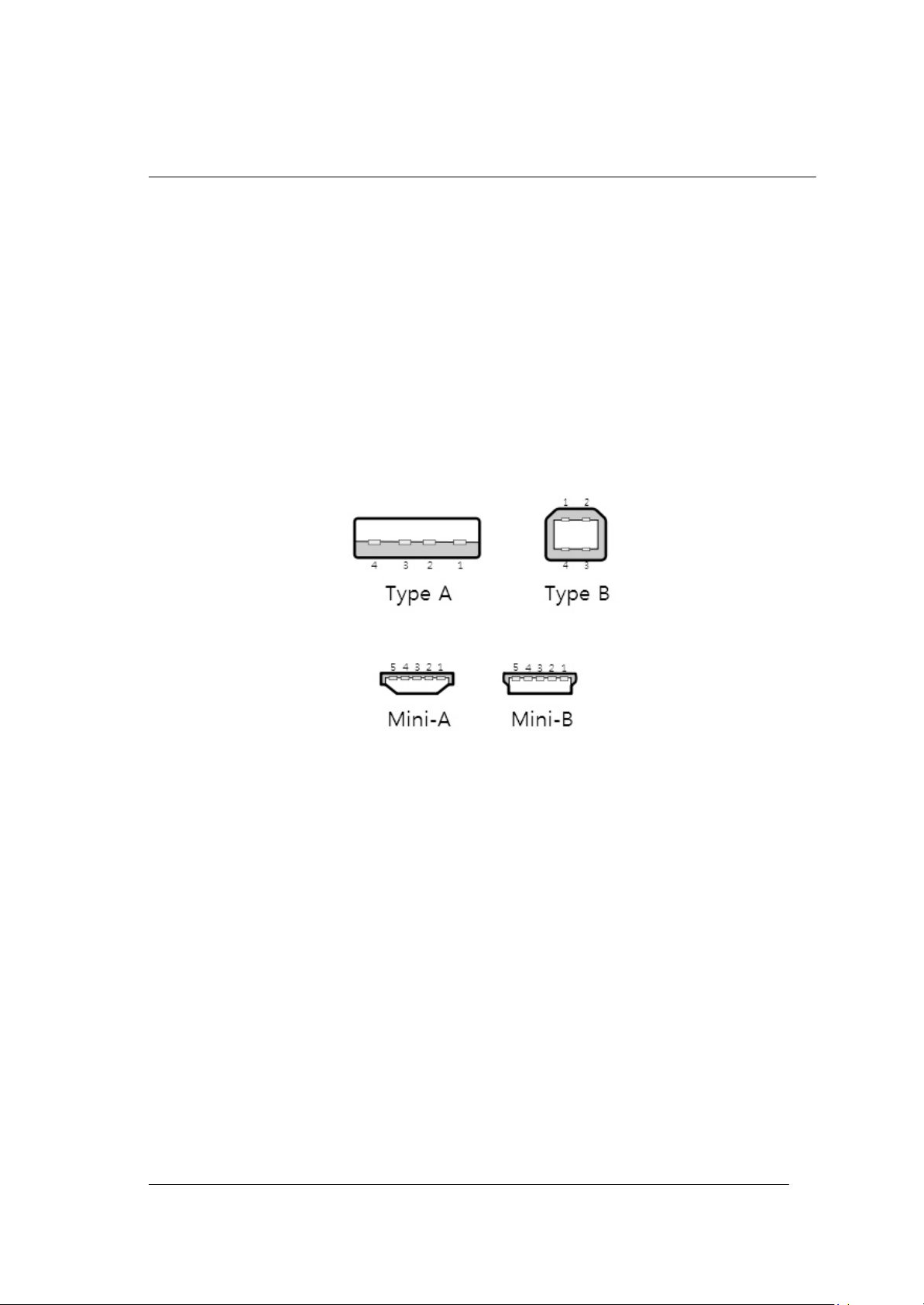
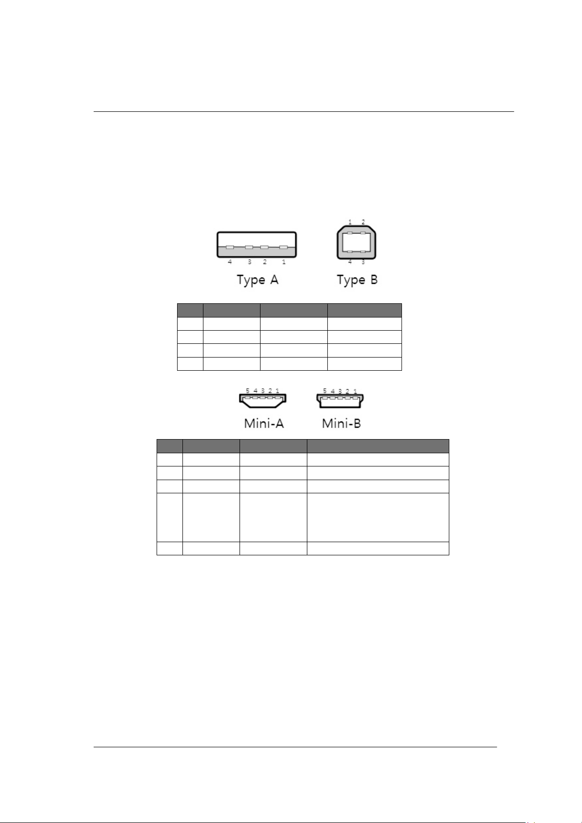
The USB connector types are Type A, Type B, Mini-A and Mini-B. Type A and Mini-B are applied to
Spinpoint M8U.
Figure 4.3 illustrates USB connector type.
Figure 4-3 USB connector type
Spinpoint M8U-Internal Product Manual REV 3.4
17
INSTALLATION
Pin
Name
Cable color
Definition
1
VCC
Red
+5V
2
D-
White
Data -
3
D+
Green
Data +
4
GND
Black
Ground
Pin
Name
Cable color
Definition
1
VCC
Red
+5V
2
D-
White
Data -
3
D+
Green
Data +
5
GND
Black
Signal Ground
Table 4-1 lists the signals connection on the USB interface.
Table 4-1 USB Connector Pin Definitions
4
ID
none
Permits distinction of
Micro-A and Micro-B plug
Type A : connected to ground
type B : not connected
Spinpoint M8U-Internal Product Manual REV 3.4
18
INSTALLATION
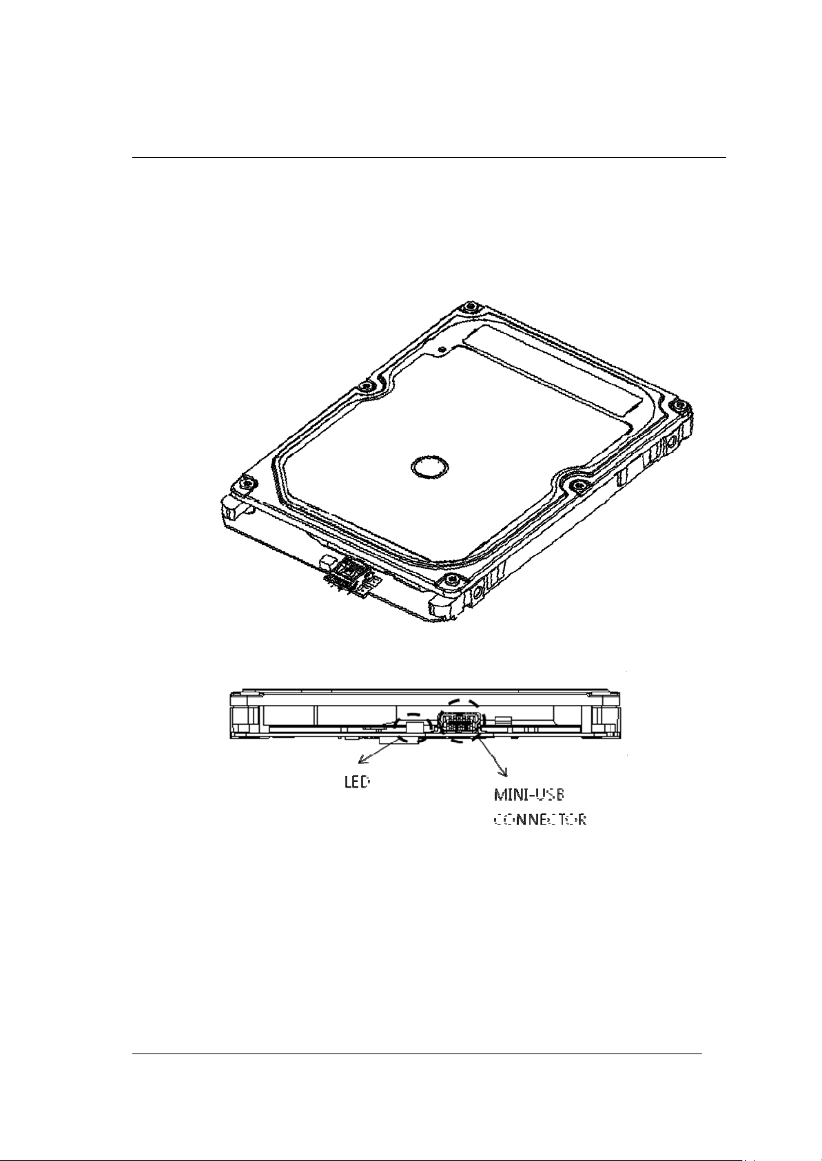
Figures 4.6 and 4.7 illustrates USB connector locations on the Spinp oin t M 8 U .
Figure 4-4 USB Interface

Spinpoint M8U-Internal Product Manual REV 3.4
19
INSTALLATION
4.5 Drive Installation
The Spinpoint M8U hard disk drive can be installed in an USB-compatible system:
• To install the drive with a motherboard that contains USB port (type A), connect the drive to the USB
port using a USB plugs (type A).
• If the drive connect to the USB Hub or Keyboard USB port, make the drive bad detection or bad
operation (because of low bus power).
• If some OS in PC System or Host can not detection the drive, the system need USB driver installation.

Spinpoint M8U-Internal Product Manual REV 3.4
20
INSTALLATION
Capacity
4.6 System Startup Procedure
Once the Spinpoint M8U hard disk drive and along with the adapter board (if required) have been installed in
your system, the drive can now be partitioned and formatted for operation. To set up the drive correctly,
follow these instructions:
1. Power on the system.
2. Typically the system will detect a configuration change automatically. If so, then jump to step 5.
3. Connected Drive Detection normally as removable disk but can not access drive folder, please create
partition & format first.
4. Perform the following steps that applies to your system: (example for XP)
I. Select Control Panel - Computer Management - Disk Manager in OS Utility.
II. Click the right mouse button of Selected USB device disk, and select New Partition.
III. Step 1. Click Next Button.
IV. Step 2. Select Partition Type and Click Next Button.
V. Step3. Select Partition Size and Click Next Button
VI. Step 4. Assign Drive Letter and Click Next Button.
VII. Step 5. Select File System, quick format option and Click Next Button.
VIII. Step 6. Click Finish Button
5. If the system recognizes the drive but experiences problem on properly handling the full capacity of the
drive, run Disk Manager utility program provided by Samsung and follow the instructions. The Disk
Manager utility program is available from Samsung on a floppy diskette, or downloadable from the
Samsung website at
system will not boot up, then contact technical support.
http://www.seagate.com If, after all these steps are successfully completed, your
Table 4-2: Logical Drive Parameters
DESCRIPTION
Total Number of
logical sectors
ST320LM008 ST500LM016 ST750LM024 ST1000LM026
625,142,448 976,773,168 1,465,149,168 1,953,525,168
320GB 500GB 750GB 1TB
NOTES:
• The total numbers of sectors is calculated by (Cylinders x Heads x Sectors) of the selected drive
type.
• 1MB = 1,000,000 Bytes, 1GB = 1,000,000,000 Bytes
Accessible capacity may vary as some OS uses binary numbering system for reported capacity.
• Windows 95 or 98 that use FAT16 file system will limit the drive’s logical partition at 2.1GB per
logical drive. Windows95 OSR2 or later allow for the FAT32 file system which provides access to
greater than 2GB of logical capacity.
• A low-level format is not required, as this was done at the factory before shipment.

Spinpoint M8U-Internal Product Manual REV 3.4
21
INSTALLATION
CHAPTER 5 DISK DRIVE OPERATION
This chapter describes the operation of the Spinpoint M8U hard disk drive functional subsystems. It is
intended as a guide to the operation of the drive, rather than a detailed theory of operation.
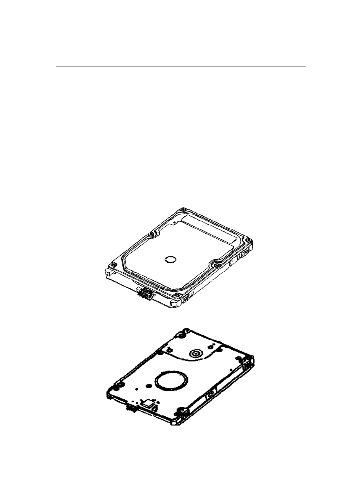
5.1 Head / Disk Assembly (HDA)
The Spinpoint M8U hard disk drive consists of a mechanical sub-assembly and a printed circuit board
assembly (PCBA), as shown in Figure 5-1. This section describes the mechanism of the drive.
The head / disk assembly (HDA) contains the mechanical sub-assemblies of the drive, which are sealed
between the aluminum-alloy base and cover. The HDA consists of the base casting assembly (which
includes the DC spindle motor assembly), the disk stack assembly, the head stack assembly, and the rotary
voice coil motor assembly (which includes the actuator latch assembly). The HDA is assembled in a clean
room. These subassemblies cannot be adjusted or field repaired.
CAUTION: To avoid contamination in the HDA, never remove or adjust its cover
and seals. Disassembling the HDA voids your warranty.
The Spinpoint M8U hard disk drive models and capacities are distinguished by the number of heads and
The ST320LM008 have one (1) disk and two (2) read/write heads. The ST500LM016 has one (1) disk
disks.
and two (2) heads. The ST750LM024 have two (2) disks and four (4) read/write heads. The ST1000LM026
has two (2) disks and four (4) read/write heads.
5.1.1 Base Casting Assembly
A one piece, aluminum-alloy base casting provides a mounting surface for the drive mechanism and PCBA.
The base casting also serves as the flange for the DC spindle motor assembly. A gasket provides a seal
between the base and cover castings that enclose the drive mechanism.
5.1.2 DC Spindle Motor Assembly
The DC spindle motor assembly consists of the brush-less three-phase motor, spindle bearing (FDB)
assembly, disk mounting hub, and a lab yrinth seal. The entire spindle motor assembly is completely
enclosed in the HDA and integrated to the base castin g. The labyrinth seal prevents bearing lubricant from
coming out into the HDA.

Spinpoint M8U-Internal Product Manual REV 3.4
22
INSTALLATION
Figure 5-1: Exploded Mechanical View
 Loading...