

SAMSUNG ST54T6X, ST54T6XAP Service Manual

Alignment and Adjustments
Samsung Electronics 4-1
4. Alignment and Adjustments
4-1 When entering the service mode:
1. Turn on the TV, and then select “STANDARD”on the picture adjustment mode.
2. Turn off the TV (STAND-BY).
3. Enter the service mode by pressing the remote control keys in the following sequence :
MUTE 1→8→2→Power On
Note : If necessary, re-do steps 1~3.
Initial display when the service mode is switched.
SERVICE NORMAL 480P
GEOMETRICS
PICTURE
PICTURE2
SOUND
PIP
OPTION
READ
RESET
1. When a RF signal is received
SERVICE NORMAL 1080i
GEOMETRICS
PICTURE
PICTURE2
SOUND
PIP
OPTION
READ
RESET
2. When a DTV signal is received
Alignment and Adjustments
4-2 Samsung Electronics
MAIN MENU
ZOOM
COMPRESS
FREEZE
SET UP
RESET
EXIT
3. When the PC mode is switched
MAIN MENU MENU DISPLAY
CH UP/DOWN Select item by moving cursor
VOL UP/DOWN Decrease or increase the adjustment values
4. Service Mode Control Keys
Note : The PC mode can be switched to the service mode by pressing the
F.Mode Key (only on the factory remote control).
Alignment and Adjustments
Samsung Electronics 4-3
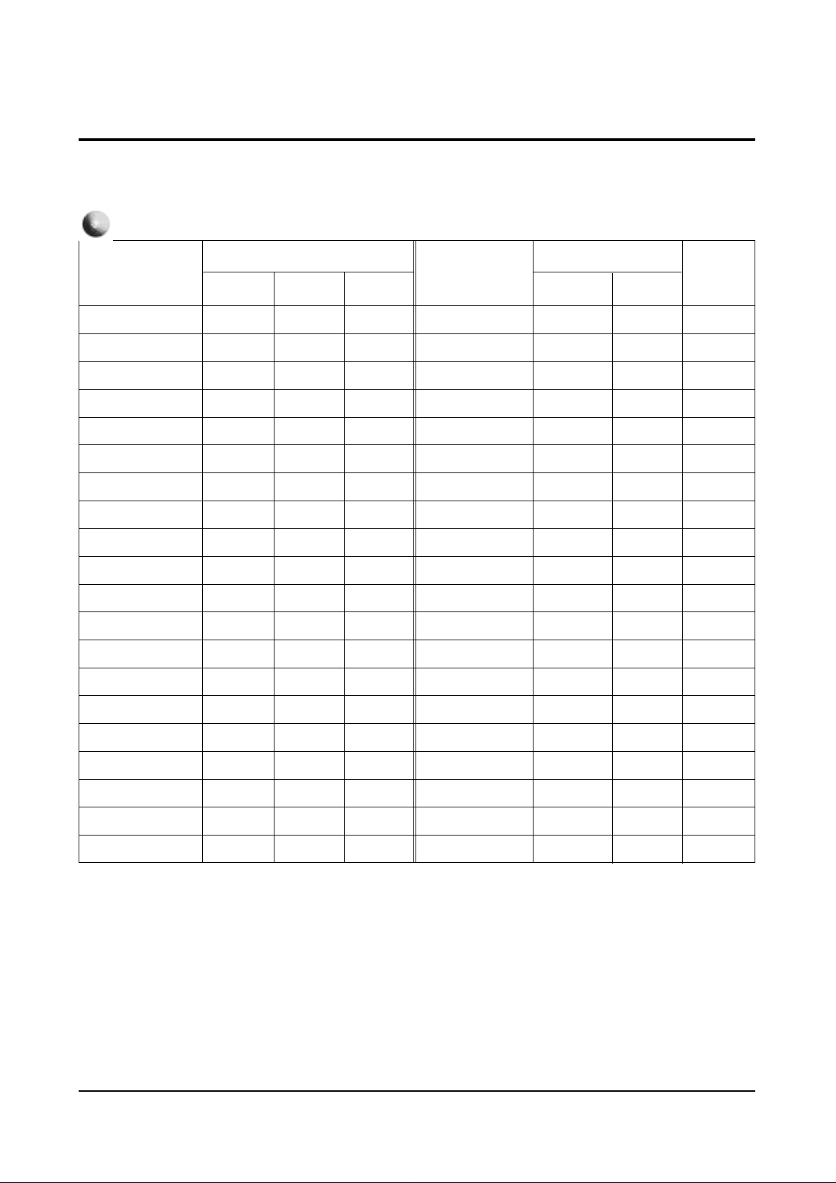
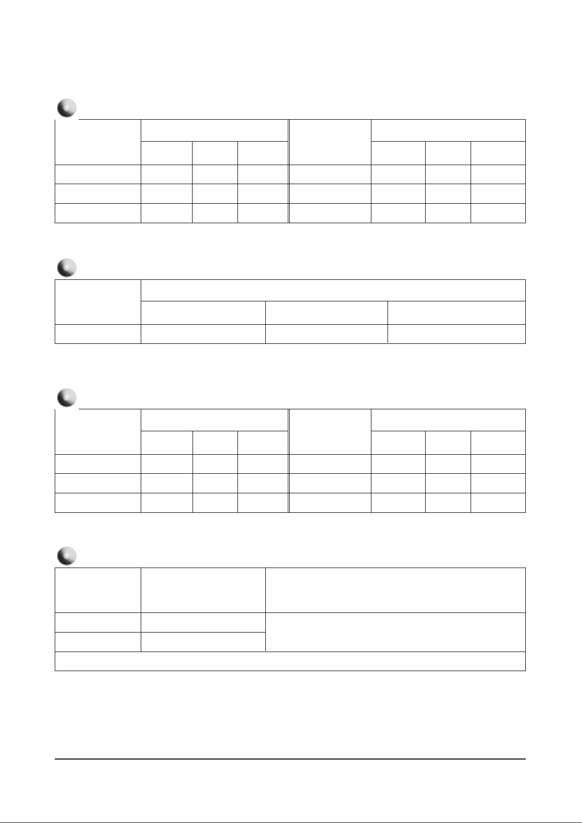
Item
TV/480P
Item
1080i
43”
53” 61”
VS
VA
VL
VSC
VE
HA
PPH
PA
UPC
LOC
132
122
114
104
0
80
100
96
128
128
132
122
114
104
0
80
100
96
128
128
114
88
114
104
0
80
100
96
128
128
HEH
HS
VAN
VBO
HSP
VS4
VA4
HS4
HA4
HP4
0
63
131
128
141
150
96
56
106
131
0
63
131
128
141
150
96
56
106
131
0
60
131
128
141
125
53
45
54
VS
VA
VL
VSC
VE
HA
PPH
PA
UPC
LOC
HEH
HS
VAN
VBO
HSP
VS4
VA4
HS4
HA4
HP4
53”
61”
Remark
128
75
114
104
0
114
100
96
128
128
0
65
131
128
139
150
96
56
106
131
91
96
62
125
53
45
54
GEOMETRIC
4-2 Facotry Data
4-2-1 Progressive
Alignment and Adjustments
4-4 Samsung Electronics
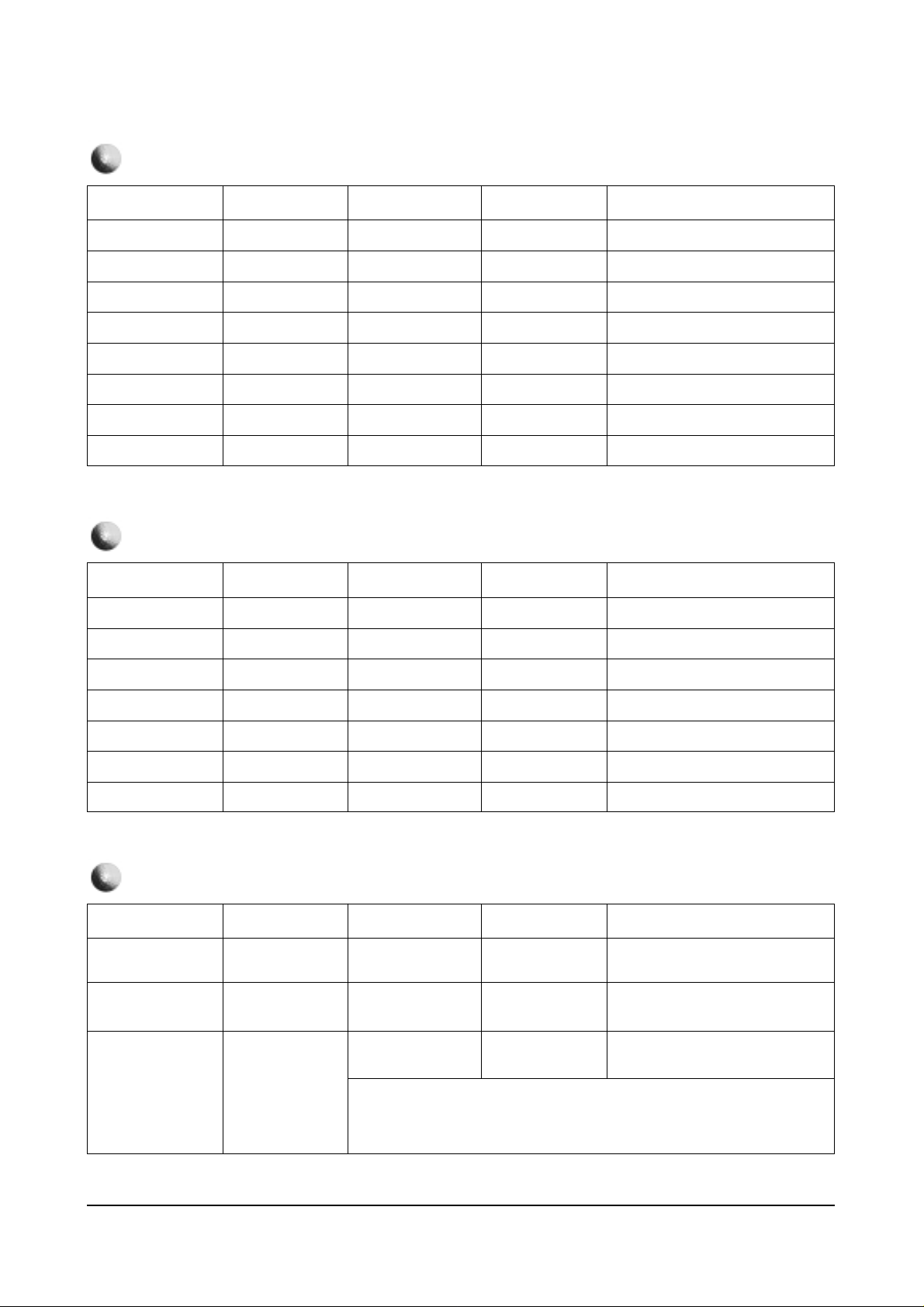
Model
Remark
OPTION
PCJ533RF
PCJ533R
PCJ534RF
PCK520R
PCJ614RF
PCK5315R
PCK6115R
Byte
Model
Byte
PCJ534R
HCJ552W
HCJ652W
BYTE 0 : 71
BYTE 1 : 54
BYTE 0 : 71
BYTE 1 : 50
BYTE 0 : 71
BYTE 1 : 44
BYTE 0 : 71
BYTE 1 : 40
BYTE 0 : 79
BYTE 1 : 41
BYTE 0 : 39
BYTE 1 : 41
Item
Remark
PICTURE
RDR
GDR
BDR
RCT
GCT
BCT
ABM
ATH
Picture
Item
Picture
20
20
20
31
31
31
1
1
RYR
RYB
GYR
GYB
GAM
HWD
HTM
HSE
2
13
12
9
12
2
1
0
Item
Remark
PICTURE 2
SBR
SCT
SCL
SHU
CTI
SSP
SFO
Picture
Item
Picture
31
7
12
8
1
2
2
POV
LTI
VML
VMD
DCT
DPC
3
2
2
3
3
1
Alignment and Adjustments
Samsung Electronics 4-5
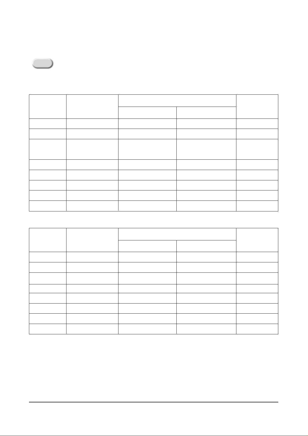
Item
Initial Value
Item
Initial Value
43”
VS
VA
VCP
VLN
VSC
HS
HPC
HA
HPP
HAA
HAB
HUC
32
32
0
5
3
0
17
20
8
11
0
8
HLC
VAS
VSR
VUV
VLV
VJS
VZS
VRP
VBS
HBS
HLB
HRB
43”
Remark
8
40
25
0
0
0
0
3
3
0
15
15
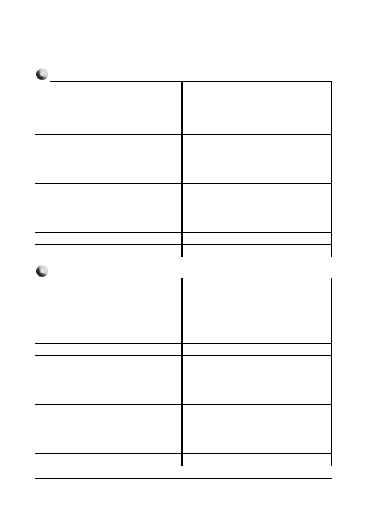
GEOMETRIC
4-2-2 Interlace
Remark
Variable
Variable
Variable
Variable
Item
Initial Value
Item
Initial Value
43”
DCT
DPI
AS
DCL
ABL
POV
SFO
TA
SCT
SBT
SCR
STT
GA
1
1
1
1
1
2
1
1
5
8
7
9
32
BA
GC
BC
GAM
AFC
TO
SSP
AMS
FHS
CFS
SC
LWC
COR
PICTURE
Remark
Variable
52”
43”
32
8
8
2
2
1
5
1
0
0
30
32
50
Remark
Variable
Variable
Variable
Variable
52”
32
8
8
2
2
1
5
1
0
0
30
32
50
Alignment and Adjustments
4-6 Samsung Electronics
Item
Initial Value
Item
Initial Value
43”
PIC
HUE
BRT
55
7
8
RYR
RYB
SHP
PICTURE 2
REMARK
52”
55
7
8
43”
15
15
0
REMARK
52”
15
15
0
Item
Initial Value
43”
SEPERATE
15
SOUND
Remark
52”
16
Item
Initial Value
Item
Initial Value
43”
Contrast
HUE
POS-HOR-L
5
3
32
POS-HOR-R
POS-VER-U
POS-VER-D
PIP
REMARK
Variable
52”
5
3
32
43”
29
21
21
REMARK
52”
29
21
21
Item
Initial Value
Byte0
Byte1
91
01
OPTION
Remark
Dissimilar initial values by model and function
Aging Off
Alignment and Adjustments
Samsung Electronics 4-7
Byte : 00
Name
D7
D6
D5
D4
D3
D2
D1
D0
SharpCenter50En
CXA1839(DVD)
V-Chip
AFN
Auto Power On
Note 1
Remark
Current Set Setting
Option adjustment is done in the service mode
0
X
Sharpness, Color, Tint
adjustment available
in the DVD Menu
X
X
X
1
Operate
Sharpness, Color, Tint
not adjustable
in the DVD Menu
Operate
Operate
Operate
Function
SZM-386U OPTION TABLE
Byte : 01
Name
D7
D6
D5
D4
D3
D2
D1
D0
3D Comb-filter
All Mighty Conv.
Remark
0
UPD6488
X
1
UPD64082
Operate
Function
Alignment and Adjustments
4-8 Samsung Electronics
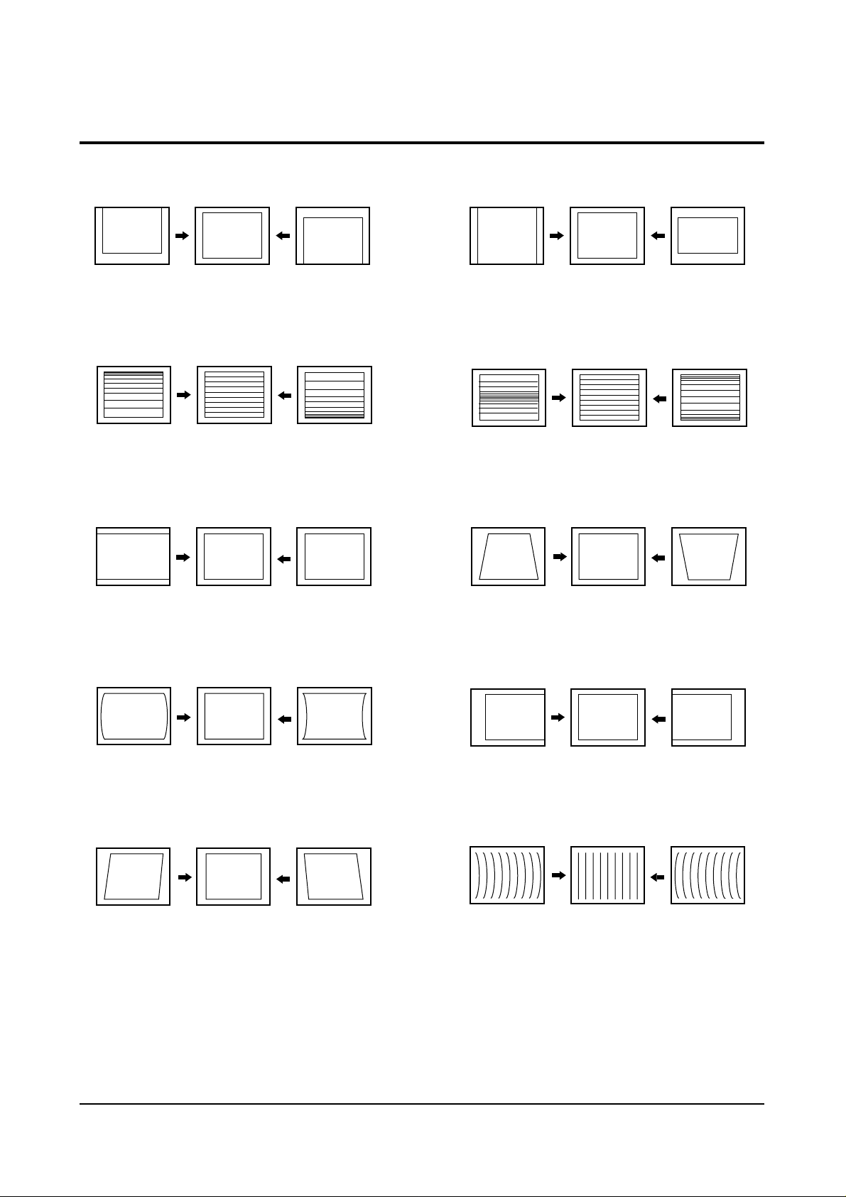
4-2 Screen Change (When adjusting I2C Bus Geometric items)
1 V SHIFT
2 V LINEARITY
3 H SIZE
6 V SIZE
7 V - S - CORRECTION
8
PIN PHASE
4
PIN AMP
5 V ANGLE
9 H SHIFT
10 V BOW
Alignment and Adjustments
Samsung Electronics 4-9
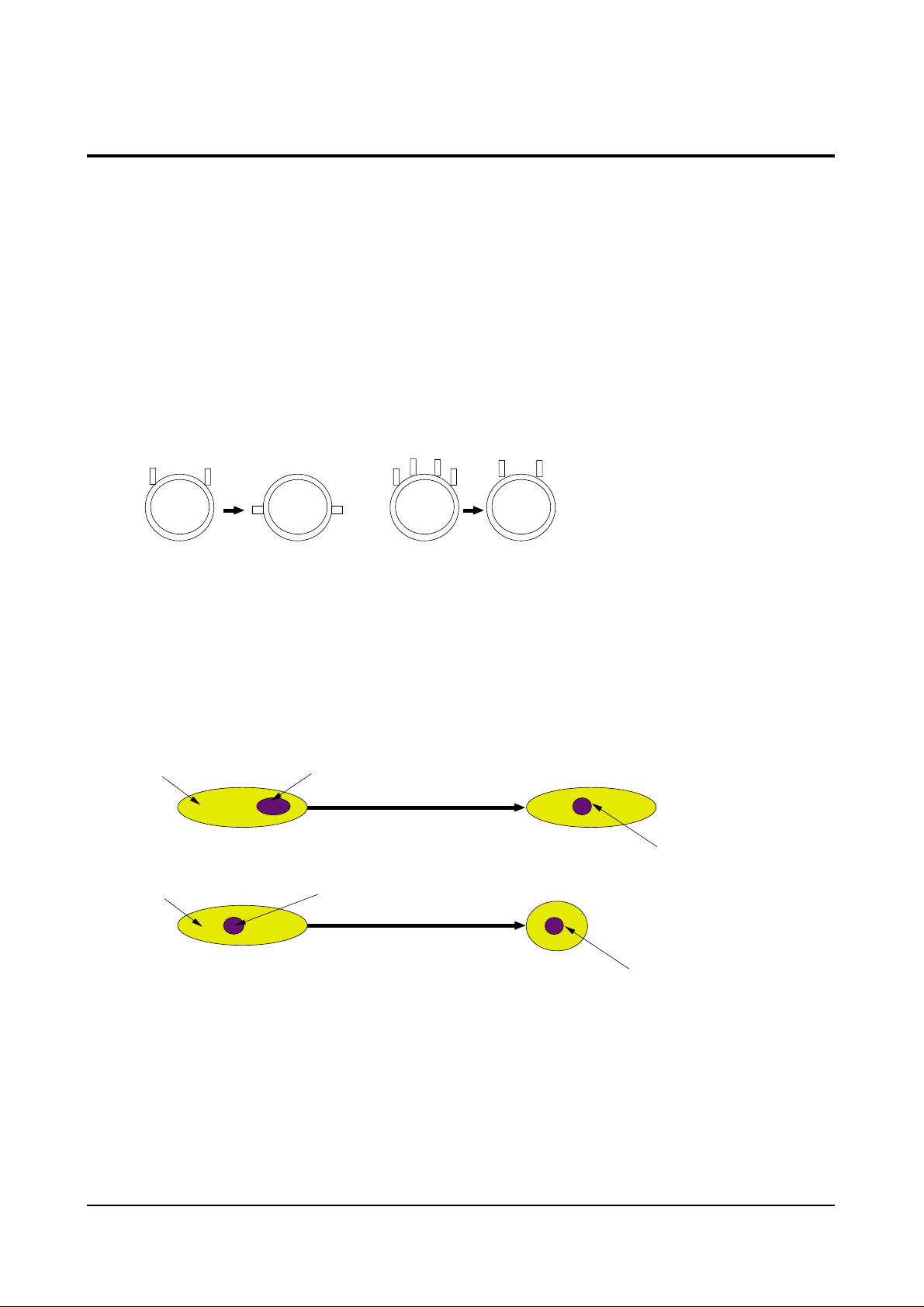
4-3 Beam Alignment
PRECAUTION
1. Input a crosshatch and dot pattern.
2. Select the “STANDARD” video mode.
3. Warm up the TV for at least 10 minutes.
4. Connect an audio oscillator to the pin jig between GT401~GT402 (located on the deflection
PCB) and GND.
5. Determine the ZERO-magnet area (using the beam-alignment CY)
6. Check the squarewave at the point where the focus is misaligned (Use an audio oscillator).
ADJUSTMENT
1. Cover the Red and Blue lenses.
2. Adjust the Green lens as shown in the figures below
3. Adjust the G-Focus until any light around the core disappears.
4. Cover the Green and Blue lenses.
5. Adjust the Red lens using the same method as with the Green lens.
6. Note: The Blue lens is not adjusted because its focus varies little (VM-coil is installed).
7. After the adjustments are completed, disconnect the jig pin connector.
(Creation of CPM Zero Magnet)
(Creation of the 2-pole/4-pole zero magnets)
G-FOCUS
(Varying G-Focus Pack)
G-FOCUS
(When VM 2-Pole Adjustment is completed)
CORE
CORE
Varying the 2-pole of VM
Varying the 4-pole of VM
(Positioning the Core in the Center)
(Adjust until the light around
the core becomes a circle)

Alignment and Adjustments
4-10 Samsung Electronics
4-4 Other Adjustments
4-4-1 Screen Adjustment
1. Warm up the TV for at least 30 minutes.
2. Turn to the Video Mode (No Signal) using a
remote-control.
3. Connect an oscilloscope to RK,GK,BK.
4. Adjust the VR (VR501, VR531, VR561) screen
so that RK, GK, BK pulse is 20Vp-p each.
(Turn the R,G,B VR screen fully
counterclockwise in the area of each flyback
line.)
4-4-2 White Balance Adjustment
1. Select the “STANDARD” video mode.
2. Input 100% white pattern.
3. In the stand-by mode, press the remote-control
keys in the following sequence:
Mute → 1 → 8 → 2 → Power ON
4. Warm up the TV for at least 30 minutes.
5. Input a 10-step signal.
6. R-cut off, B-cut off, and G-cut off by pressing
the Volume +/- keys.
7. Adjust the low light with viewing the dark
side of the screen.
8. Select R-drive, G-drive, and B-drive by
pressing the Volume +/- keys.
9. Adjust the high light with viewing the light
side of the screen.
10. If necessary, redo adjustments 6~9.
11. Press the Menu key to exit.
4-4-3 Sub-Brightness Adjustment
1. Input a sub-brightness adjustment signal.
(TOSHIBA PATTERN)
2. In the stand-by mode, press the remote-control
keys in the following sequence :
Mute - 1 - 8 - 2 - Power ON
3. Select SBT by pressing the Volume +/- keys.
4. Adjust so that the 7th step on the right side of
the screen is not seen (Use the Volume +/keys).
5. Press the Menu key to exit.
4-4-4 High Voltage (31KV) Check
PRECAUTION
1. Input a lion head pattern.
2. Select “STANDARD” video mode.
3. Warm up the TV for at least 10 minutes.
4. Use a 1000:1 probe.
ADJUSTMENT
1. Connect the (+) terminal of the 1000:1 probe to
the high voltage distributor and the (-)
terminal to GND (located on the deflection
board).
2. Adjust VR471 (located on the deflection board)
so that the digital meter indicates
DC 31V ± 0.1V.
Alignment and Adjustments
Samsung Electronics 4-11
4-4-5 F.S. (Fail Safe) Circuit Check
Note : The F.S. Circuit check must be performed
after servicing.
1. Turn on the TV.
2. Select the “STANDARD” video mode.
3. Short GT18, GT17 (located on the
Convergence PCB). Then, both sound and
picture disappear. (Note: Even if the shorted
terminals are removed, both sound and
picture do not appear. This proves the F.S.
circuit is working. )
4. To restore both sound and picture, turn off the
TV and reset it after about 30 seconds.
4-4-6 Static Focus Adjustment
PRECAUTION
1. Select the “STANDARD” video mode.
2. Input a crosshatch pattern.
3. Cover the lenses that are not being adjusted.
4. Connect a convergence jig and read data.
5. Adjust the lens for best focus.
(See Fig, 4-1, next page)
STATIC FOCUS (CONTINUED)
Vary the focus pack VR (Red, Blue) on the
front cabinet. Adjust the TV for best possible
focus around the center of the crosshatch
pattern, without losing overall screen balance.
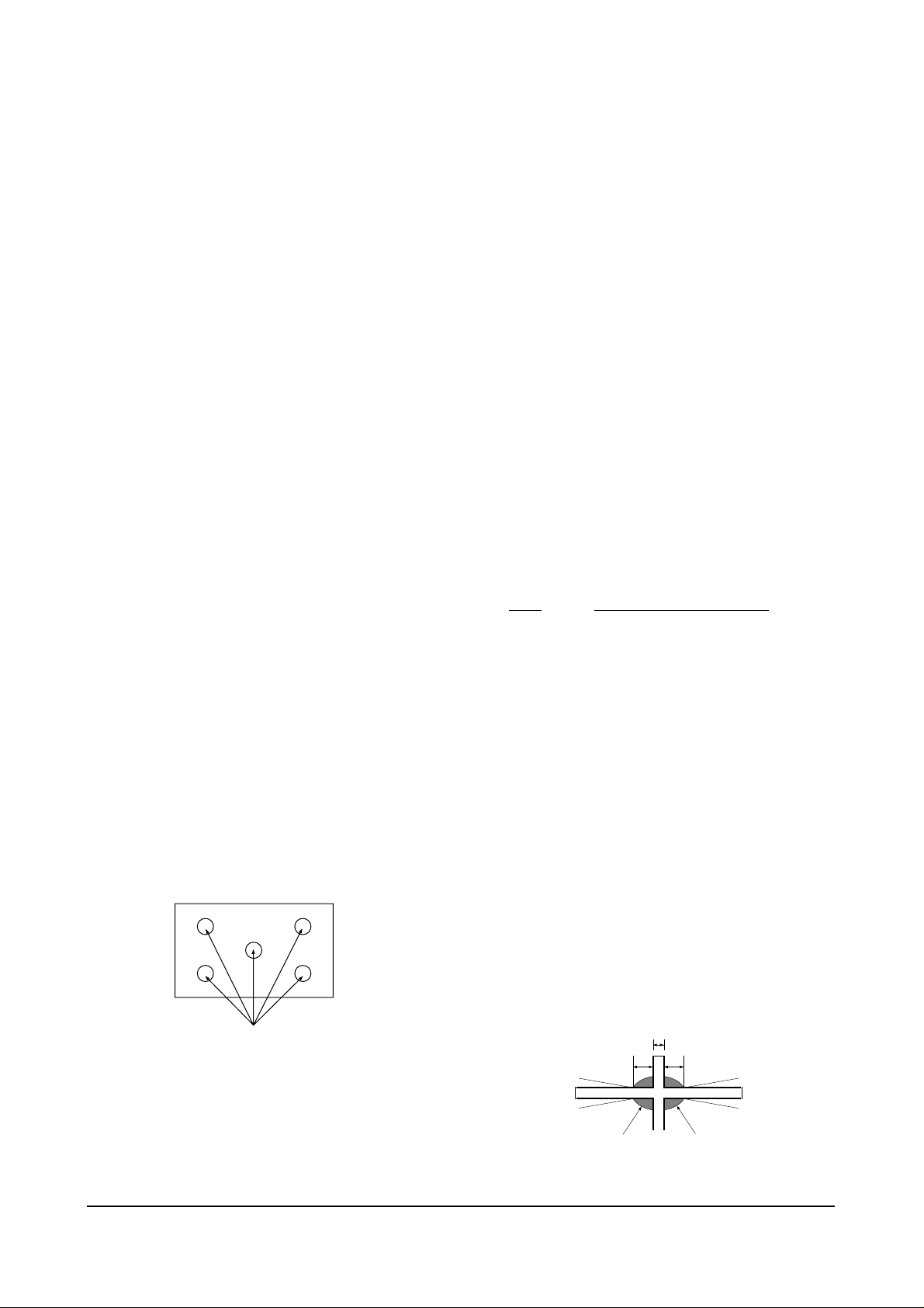
Figure Crosshatch Pattern
Examine these points together.
4-4-7 Lens Focus Adjustment
PRECAUTIONS
1. Do this adjustment after the static focus
adjustment and the tilt adjustment.
2. Select the “STANDARD” video mode.
(Contrast:64, Brightness:32)
3. Input a crosshatch pattern.
ADJUSTMENT
1. Loosen the lens screws.
2. Cover the two lenses that are not being
adjusted.
3. Adjust the lens, observing the color aberration
vertically and horizontally within 3 blocks of
the center of the crosshatch pattern.
4. When the lens is turned clockwise, the color
aberration will change as follows:
Lens
Color Aberration Change
R Orange - Crimson
G Blue - Red
B Purple - Green
5. Green lens adjustment:
Set the lens at the point where Blue just
changes to Red. If the color aberration is
irregular throughout the picture screen, adjust
the lens to show Red color aberration
(approximately 1~3 mm area) within a 3-block
grid around the horizontal center-line. If the
color aberration is irregular, adjust the lens as
shown in the diagram below. (Accurate
alignment of Green is important for overall
color quality.)
6. Red lens adjustment
Set the Red lens at the point where Orange
becomes Crimson.
7. Blue lens adjustment
Set the Blue lens at the point where Purple
becomes Green.
P
L1
L2
RED ABERRATION
BLUE ABERRATION
L1, L2 < P
_
Fig. 4-1 Crosshatch Pattern.
Fig. 4-2 Color Aberration
Examine these points together

Alignment and Adjustments
4-12 Samsung Electronics
4-4-8 Horizontal Dynamic Focus Adjustment
PRECAUTION
1. Input a crosshatch pattern.
2. Select the “STANDARD” video mode.
3. Warm up the set for at least 10 minutes.
ADJUSTMENT
1. Cover the Red and Blue lenses.
2. Adjust VR491 (located on the convergence
PCB, H-Parabola).
3. Balance the left and right sides of the dynamic
focus lines.
Alignment and Adjustments
Samsung Electronics 4-13
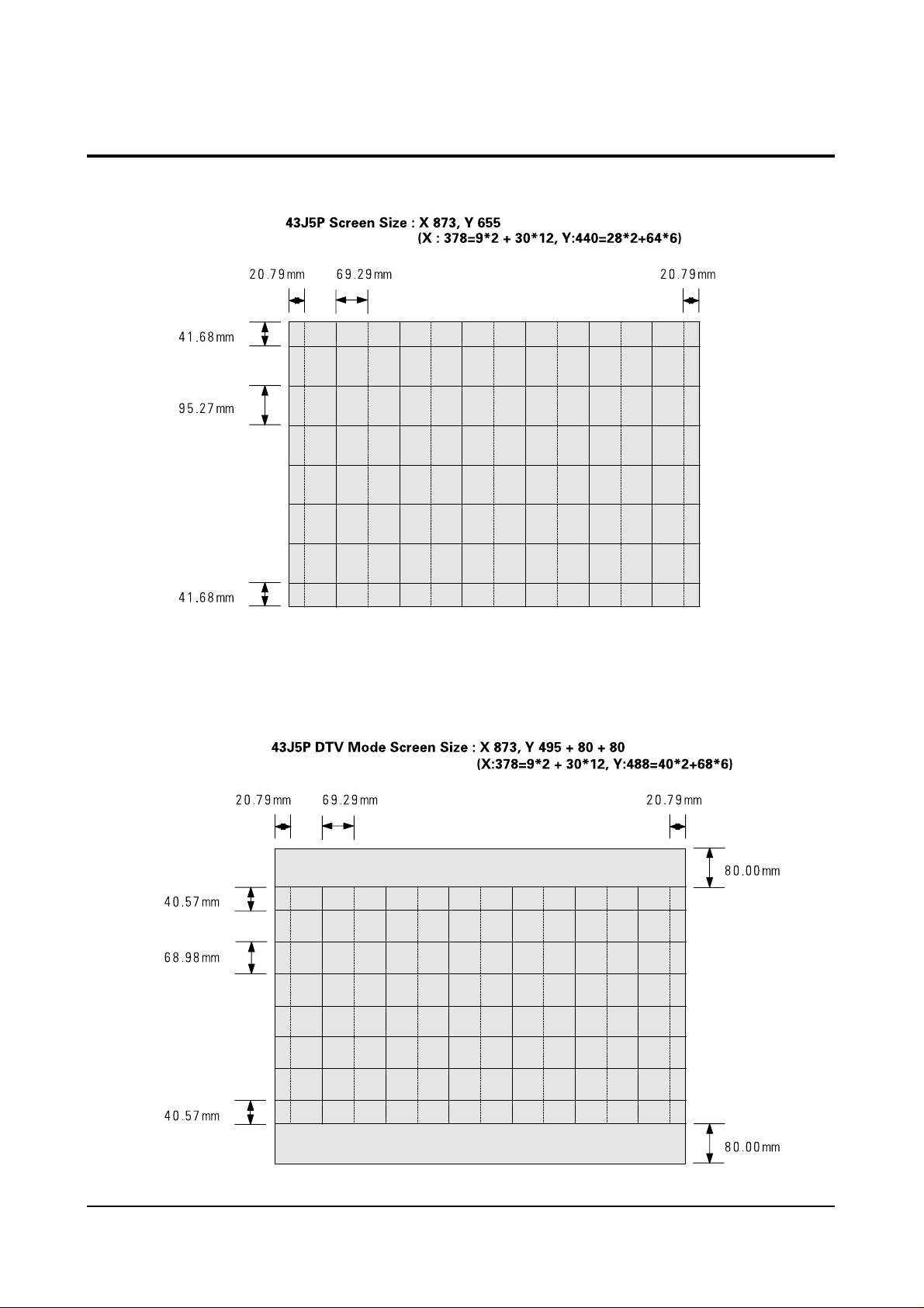
4-5 Screen-Jig
4-5-1 43J5P
4-5-2 43J5P DTV Mode
Alignment and Adjustments
4-14 Samsung Electronics
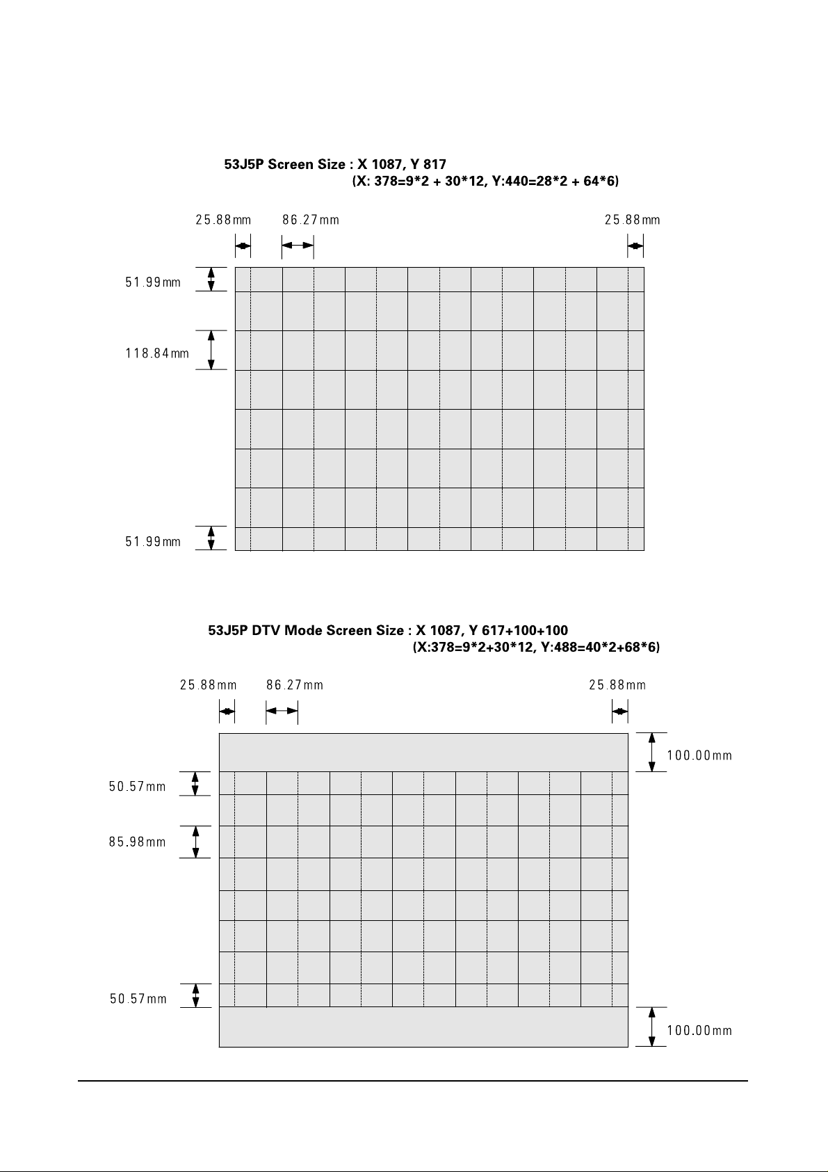
4-5-3 53J5P
4-5-4 53J5P DTV Mode
 Loading...