

Samsung ST436WMX, ST506WMX, HLK436WX, HLK506WX Schematic
fLCD PROJECTION TELEVISION
Chassis : L54A
Model : ST436WMX/GAP
ST506WMX/GAP
HLK436WX/XAA
HLK506WX/XAA
fLCD PROJECTION TELEVISION CONTENTS
Precautions
Reference Information
Specifications
Disassembly and Reassembly
Alignment and Adjustments
Operation Check &
Troubleshooting for each PCB
Board
Exploded View and Parts List
Electrical Parts List
Block Diagram
Wiring Diagram
Schematic Diagrams
1.
2.
3.
4.
5.
6.
7.
8.
9.
10.
11.

ELECTRONICS
© Samsung Electronics Co., Ltd. JUN. 2000
Printed in Korea
3L54A-4301A

1. Precautions
1-1 Safety Precautions
1. Be sure that all of the built-in protective
devices are replaced. Restore any missing
protective shields.
2. When reinstalling the chassis and its
assemblies, be sure to restore all protective
devices, including: nonmetallic control knobs
and compartment covers.
3. Make sure that there are no cabinet openings
through which people—particularly
children—might insert fingers and contact
dangerous voltages. Such openings include
the spacing between the picture tube and the
cabinet mask, excessively wide cabinet
ventilation slots, and improperly fitted back
covers.
If the measured resistance is less than 1.0
megohm or greater than 5.2 megohms, an
abnormality exists that must be corrected
before the unit is returned to the customer.
4. Leakage Current Hot Check (Figure 1-1):
Warning: Do not use an isolation
transformer during this test. Use a leakagecurrent tester or a metering system that
complies with American National Standards
Institute (ANIS C101.1, Leakage Current for
Appliances), and Underwriters Laboratories
(UL Publication UL1410, 59.7).
5. With the unit completely reassembled, plug
the AC line cord directly into the power
outlet. With the unit’s AC switch first in the
ON position and then OFF, measure the
current between a known earth ground (metal
water pipe, conduit, etc.) and all exposed
metal parts, including: antennas, handle
brackets, metal cabinets, screwheads and
control shafts. The current measured should
not exceed 0.5 milliamp. Reverse the powerplug prongs in the AC outlet and repeat the
test.
Fig. 1-1 AC Leakage Test
6. Antenna Cold Check:
With the unit’s AC plug disconnected from the
AC source, connect an electrical jumper across
the two AC prongs. Connect one lead of the
ohmmeter to an AC prong. Connect the other
lead to the coaxial connector.
7. X-ray Limits:
The picture tube is especially designed to prohibit X-ray emissions. To ensure continued
X-ray protection, replace the picture tube only
with one that is the same type as the original.
Carefully reinstall the picture tube shields and
mounting hardware; these also provide X-ray
protection.
8. High Voltage Limits:
High voltage must be measured each time servicing is done on the B+, horizontal deflection
or high voltage circuits. Correct operation of
the X-ray protection circuits must be
reconfirmed whenever they are serviced.
(X-ray protection circuits also may be called
“horizontal disable” or “hold-down”.)
Heed the high voltage limits. These include
the X–ray Protection Specifications Label, and
the Product Safety and X-ray Warning Note on
the service data schematic.
Precautions
Samsung Electronics 1-1
LEAKAGE
CURRENT
TESTER
DEVICE
UNDER
TEST
TEST ALL
EXPOSED METAL
SURFACES
2-WIRE CORD
ALSO TEST WITH
PLUG REVERSED
(USING AC ADAPTER
PLUG AS REQUIRED)
EARTH
GROUND
(READING SHOULD
NOT BE ABOVE
0.5mA)
Follow these safety, servicing and ESD precautions to prevent damage and protect against potential
hazards such as electrical shock and X-rays.

1-1 Safety Precautions (Continued)
9. High voltage is maintained within specified
limits by close-tolerance, safety-related
components and adjustments. If the high
voltage exceeds the specified limits, check
each of the special components.
10. Design Alteration Warning:
Never alter or add to the mechanical or
electrical design of this unit. Example: Do not
add auxiliary audio or video connectors. Such
alterations might create a safety hazard. Also,
any design changes or additions will void the
manufacturer’s warranty.
11. Hot Chassis Warning:
Some TV receiver chassis are electrically
connected directly to one conductor of the AC
power cord. If an isolation transformer is not
used, these units may be safely serviced only
if the AC power plug is inserted so that the
chassis is connected to the ground side of the
AC source.
To confirm that the AC power plug is inserted
correctly, do the following: Using an AC
voltmeter, measure the voltage between the
chassis and a known earth ground. If the
reading is greater than 1.0V, remove the AC
power plug, reverse its polarity and reinsert.
Re-measure the voltage between the chassis
and ground.
12. Some TV chassis are designed to operate with
85 volts AC between chassis and ground,
regardless of the AC plug polarity. These units
can be safely serviced only if an isolation
transformer inserted between the receiver and
the power source.
13. Some TV chassis have a secondary ground
system in addition to the main chassis ground.
This secondary ground system is not
isolated from the AC power line. The two
ground systems are electrically separated by
insulating material that must not be defeated
or altered.
14. Components, parts and wiring that appear to
have overheated or that are otherwise
damaged should be replaced with parts that
meet the original specifications. Always
determine the cause of damage or overheating, and correct any potential hazards.
15. Observe the original lead dress, especially
near the following areas: Antenna wiring,
sharp edges, and especially the AC and high
voltage power supplies. Always inspect for
pinched, out-of-place, or frayed wiring. Do
not change the spacing between components
and the printed circuit board. Check the AC
power cord for damage. Make sure that leads
and components do not touch thermally hot
parts.
16. Picture Tube Implosion Warning:
The picture tube in this receiver employs
“integral implosion” protection. To ensure
continued implosion protection, make sure
that the replacement picture tube is the same
as the original.
17. Do not remove, install or handle the picture
tube without first putting on shatterproof
goggles equipped with side shields. Never
handle the picture tube by its neck. Some
“in-line” picture tubes are equipped with a
permanently attached deflection yoke; do not
try to remove such “permanently attached”
yokes from the picture tube.
18. Product Safety Notice:
Some electrical and mechanical parts have
special safety-related characteristics which
might not be obvious from visual inspection.
These safety features and the protection they
give might be lost if the replacement component differs from the original—even if the
replacement is rated for higher voltage,
wattage, etc.
Components that are critical for safety are
indicated in the circuit diagram by shading,
( ) or ( ).
Use replacement components that have the
same ratings, especially for flame resistance
and dielectric strength specifications.
A replacement part that does not have the
same safety characteristics as the original
might create shock, fire or other hazards.
Precautions
1-2 Samsung Electronics

1-2 Servicing Precautions
1. Servicing precautions are printed on the
cabinet. Follow them.
2. Always unplug the unit’s AC power cord from
the AC power source before attempting to: (a)
Remove or reinstall any component or
assembly, (b) Disconnect an electrical plug or
connector, (c) Connect a test component in
parallel with an electrolytic capacitor.
3. Some components are raised above the printed
circuit board for safety. An insulation tube or
tape is sometimes used. The internal wiring is
sometimes clamped to prevent contact with
thermally hot components. Reinstall all such
elements to their original position.
4. After servicing, always check that the screws,
components and wiring have been correctly
reinstalled. Make sure that the portion around
the serviced part has not been damaged.
5. Check the insulation between the blades of the
AC plug and accessible conductive parts
(examples: metal panels, input terminals and
earphone jacks).
6. Insulation Checking Procedure: Disconnect the
power cord from the AC source and turn the
power switch ON. Connect an insulation
resistance meter (500V) to the blades of the AC
plug.
The insulation resistance between each blade
of the AC plug and accessible conductive parts
(see above) should be greater than 1 megohm.
7. Never defeat any of the B+ voltage interlocks.
Do not apply AC power to the unit (or any of
its assemblies) unless all solid-state heat sinks
are correctly installed.
8. Always connect a test instrument’s ground
lead to the instrument chassis ground before
connecting the positive lead; always remove
the instrument’s ground lead last.
9. When some parts inside the optical engine
(except lamp) are damaged, replace the whole
optical engine.
Precautions
Samsung Electronics 1-3
Warning1: First read the “Safety Precautions” section of this manual. If some unforeseen circumstance creates a conflict between
the servicing and safety precautions, always follow the safety precautions.
Warning2: An electrolytic capacitor installed with the wrong polarity might explode.
WARNING : This cover is provided with an interlock to reduce
the risk of excessive ultraviolet radiation.
Do not defeat its purpose or atempt to service without
removing cover completely.
CAUTION : Replace with same type numer DS001AKB

1. Some semiconductor (“solid state”) devices
are easily damaged by static electricity. Such
components are called Electrostatically
Sensitive Devices (ESDs); examples include
integrated circuits and some field-effect
transistors. The following techniques will
reduce the occurrence of component damage
caused by static electricity.
2. Immediately before handling any semicon
ductor components or assemblies, drain the
electrostatic charge from your body by
touching a known earth ground. Alternatively,
wear a discharging wrist-strap device. (Be
sure to remove it prior to applying power—
this is an electric shock precaution.)
3. After removing an ESD-equipped assembly,
place it on a conductive surface such as
aluminum foil to prevent accumulation of
electrostatic charge.
4. Do not use freon-propelled chemicals. These
can generate electrical charges that damage
ESDs.
5. Use only a grounded-tip soldering iron when
soldering or unsoldering ESDs.
6. Use only an anti-static solder removal device.
Many solder removal devices are not rated as
“anti-static”; these can accumulate sufficient
electrical charge to damage ESDs.
7. Do not remove a replacement ESD from its
protective package until you are ready to
install it. Most replacement ESDs are
packaged with leads that are electrically
shorted together by conductive foam,
aluminum foil or other conductive materials.
8. Immediately before removing the protective
material from the leads of a replacement ESD,
touch the protective material to the chassis or
circuit assembly into which the device will be
installed.
9. Minimize body motions when handling
unpackaged replacement ESDs. Motions such
as brushing clothes together, or lifting a foot
from a carpeted floor can generate enough
static electricity to damage an ESD.
Precautions
1-4 Samsung Electronics
1-3 Precautions for Electrostatically Sensitive Devices (ESDs)

Reference Information
Samsung Electronics 2-1
2. Reference Information
2-1 Tables of Abbreviations and Acronyms
A
Ah
Å
dB
dBm
°C
°F
°K
F
G
GHz
g
H
Hz
h
ips
kWh
kg
kHz
kΩ
km
km/h
kV
kVA
kW
I
MHz
Ampere
Ampere-hour
Angstrom
Decibel
Decibel Referenced to One
Milliwatt
Degree Celsius
Degree Fahrenheit
degree Kelvin
Farad
Gauss
Gigahertz
Gram
Henry
Hertz
Hour
Inches Per Second
Kilowatt-hour
Kilogram
Kilohertz
Kilohm
Kilometer
Kilometer Per Hour
Kilovolt
Kilovolt-ampere
Kilowatt
Liter
Megahertz
MV
MW
MΩ
m
µA
µF
µH
µm
µs
µW
mA
mg
mH
mI
mm
ms
mV
nF
Ω
pF
Ib
rpm
rps
s
V
VA
W
Wh
Megavolt
Megawatt
Megohm
Meter
Microampere
Microfarad
Microhenry
Micrometer
Microsecond
Microwatt
Milliampere
Milligram
Millihenry
Milliliter
Millimeter
Millisecond
Millivolt
Nanofarad
Ohm
Picofarad
Pound
Revolutions Per Minute
Revolutions Per Second
Second (Time)
Volt
Volt-ampere
Watt
Watt-hour
Table 2-1 Abbreviations

Reference Information
2-2 Samsung Electronics
Table 2-1 Abbreviations
ABL
AC
ACC
AF
AFC
AFT
AGC
AM
ANSI
APC
APC
A/V
AVC
BAL
BPF
B-Y
CATV
CB
CCD
CCTV
Ch
CRT
CW
DC
DVM
EIA
ESD
ESD
FBP
FBT
FF
FM
FS
GND
G-Y
H
HF
HI-FI
IC
IC
IF
Automatic Brightness Limiter
Alternating Current
Automatic Chroma Control
Audio Frequency
Automatic Frequency Control
Automatic Fine Tuning
Automatic Gain Control
Amplitude Modulation
American National Standards Institute
Automatic Phase Control
Automatic Picture Control
Audio-Video
Automatic Volume Control
Balance
Bandpass Filter
Blue-Y
Community Antenna Television (Cable TV)
Citizens Band
Charge Coupled Device
Closed Circuit Television
Channel
Cathode Ray Tube
Continuous Wave
Direct Current
Digital Volt Meter
Electronics Industries Association
Electrostatic Discharge
Electrostatically Sensitive Device
Feedback Pulse
Flyback Transformer
Flip-Flop
Frequency Modulation
Fail Safe
Ground
Green-Y
High
High-Frequency
High Fidelity
Inductance-Capacitance
Integrated Circuit
Intermediate Frequency
I/O
L
L
LED
LF
MOSFET
MTS
NAB
NEC
NTSC
OSD
PCB
PLL
PWM
QIF
R
RC
RF
R-Y
SAP
SAW
SIF
SMPS
S/N
SW
TP
TTL
TV
UHF
UL
UV
VCD
VCO
VCXO
VHF
VIF
VR
VTR
VTVM
TR
Input/output
Left
Low
Light Emitting Diode
Low Frequency
Metal-Oxide-Semiconductor-Field-Effect-Tr
Multi-channel Television Sound
National Association of Broadcasters
National Electric Code
National Television Systems Committee
On Screen Display
Printed Circuit Board
Phase-Locked Loop
Pulse Width Modulation
Quadrature Intermediate Frequency
Right
Resistor & Capacitor
Radio Frequency
Red-Y
Second Audio Program
Surface Acoustic Wave(Filter)
Sound Intermediate Frequency
Switching Mode Power Supply
Signal/Noise
Switch
Test Point
Transistor Transistor Logic
Television
Ultra High Frequency
Underwriters Laboratories
Ultraviolet
Variable-Capacitance Diode
Voltage Controlled Oscillator
Voltage Controlled Crystal Oscillator
Very High Frequency
Video Intermediate Frequency
Variable Resistor
Video Tape Recorder
Vacuum Tube Voltmeter
Transistor

Reference Information
Samsung Electronics 2-3
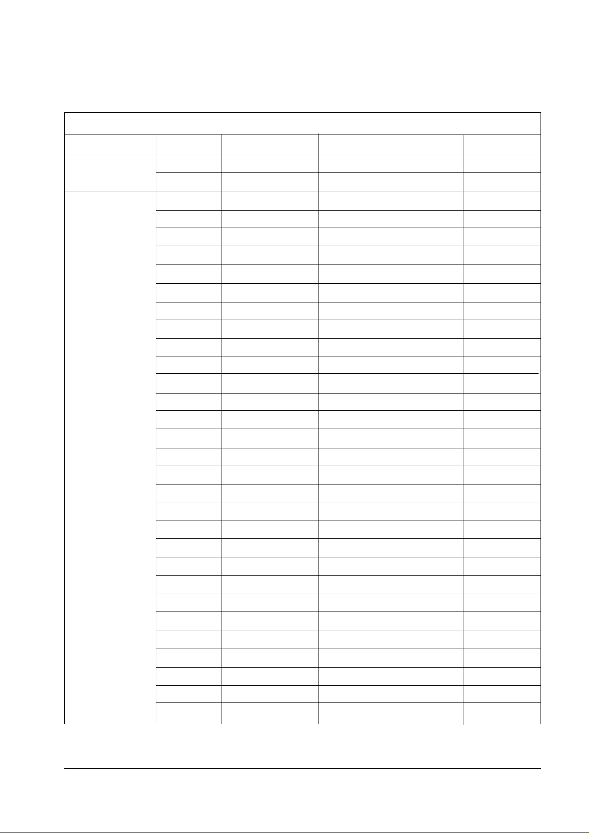
2-2 IC Line Up
Table 2 - 2 IC Line - Up
ASSY
Main
DIGITAL
LOC NO COMPONENT DESCRIPTION MAKER
TU101S AA40-00032A TUNER,TCPN3081PC09A SEMCO
TU102S AA40-00032A TUNER,TCPN3081PC09A SEMCO
IC901 0904-001121 PCF8574P,I/O Expander PHILIPS
IC902 1002-001048 PCF8591T,I/O Expander PHILIPS
IC903 0904-001121 PCF8574P,I/O Expander PHILIPS
IC701 1001-000212 TA8851AN TOSHIBA
IC201 1204-001550 CXA2101AQ SONY
IC205 0801-002319 74HCT221 PHILIPS
IC206 0801-000961 4053B SGS
IC207 0801-002319 74HCT221 PHILIPS
IC209 0801-000901 74HC04D PHILIPS
IC210 1204-001372 SDA9361 INFINEON
IC401 1001-001082 BA7657F ROHM KOREA
IC302 1204-001388 Z86129 Zilog
IC303 1001-001083 NJM2248D NJRC
IC341 1001-001083 NJM2248D NJRC
ICP01 1204-001668 SDA9488X INFINEON
M701 AA95-00346A 3D COMB Module
M601 AA95-00513A Dolby Module
ICD201 1204-001598 VPC3230D MICRONAS
ICD202 1205-001172 CIP3250A MICRONAS
ICD301 1204-001623 SDA9400 INFINEON
ICD105 1002-001179 AD9884A ANALOG DEVICE
ICD106 0801-002267 74LCX14MX FAIRCHILD
ICD108 1103-000180 24C16 ATMEL
ICD109 1204-000292 LM1881M National SEMI
ICD110 1006-001076 232 MAXIM
ICD115 1205-001713 ICS502M MICROCLOCK
ICD125 1205-001713 ICS502M MICROCLOCK
ICD165 1003-001249 PW364-S1675 PIXELWORKS
ICD119 1205-001740 DS90C385MTDX National SEMI
Reference Information
2-4 Samsung Electronics
Table 2 - 2 IC Line - Up
ASSY
DIGITAL
PANEL
DRIVE
LOC NO COMPONENT DESCRIPTION MAKER
ICD127 1106-001308 KM616V1000 SST
OTP01 1107-001087 29LV160,Flash Memory FUJITU
IC103 1203-001657 1054 LTC
IC104 1002-000134 TDA8444 PHILIPS
IC105 1002-000134 TDA8444 PHILIPS
IC106 1201-000541 TL062CDT TI
IC107 1201-000541 TL062CDT TI
IC108 1201-000541 TL062CDT TI
ICT101 1209-001271 DS1721S DALLAS
ICF101 1203-001827 L4973V3.3 THOMSON
IC201 1205-001711 DS90CF386MTD National SEMI
IC202 1205-001701 CY2309SC-1H CYPRESS
IC206 0801-002396 74LCX74 FAIRCHILD
ICR408 1205-001713 ICS502M MICROCLOCK
ICR409 1205-001701 CY2309SC-1H CYPRESS
ICG408 1205-001713 ICS502M MICROCLOCK
ICG409 1205-001701 CY2309SC-1H CYPRESS
ICB408 1205-001713 ICS502M MICROCLOCK
ICB409 1205-001701 CY2309C-1H CYPRESS
IC301 1205-001701 CY2309C-1H CYPRESS
IC302 1205-001701 CY2309C-1H CYPRESS
ICR301 0801-002172 74LCX16244 FAIRCHILD
ICG301 0801-002172 74LCX16244 FAIRCHILD
ICB301 0801-002172 74LCX16244 FAIRCHILD
ICR401 AA13-00086A SDP-9904 SST
ICR402 1105-001273 KM416S1120DT SST
ICR403 1105-001273 KM416S1120DT SST
ICR404 1105-001273 KM416S1120DT SST
ICR405 1105-001273 KM416S1120DT SST
ICR406 0801-002394 74LCX32MX FAIRCHILD
ICR407 1205-001701 CY2309C-1H CYPRESS
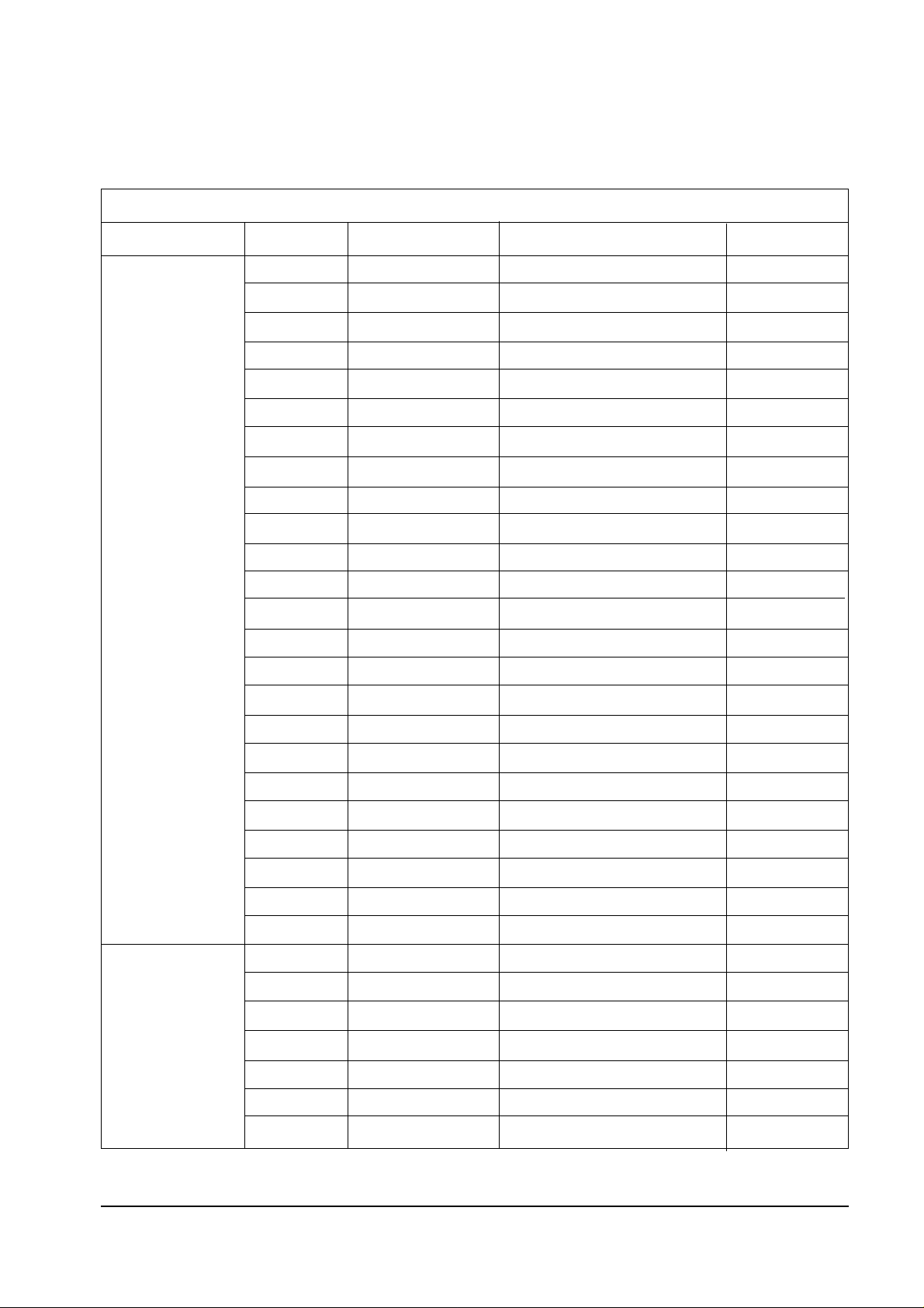
Reference Information
Samsung Electronics 2-5
Table 2 - 2 IC Line - Up
ASSY
PANEL
DRIVE
POWER &
SOUND
LOC NO COMPONENT DESCRIPTION MAKER
ICR501 1001-001106 DG409CY MAXIM
ICR504 1201-000541 TL062CDT TI
ICT501 1001-000163 74HC4051 FAIRCHILD
OTP02 AA13-30006B AT89C52-24 ATMEL
ICG401 AA13-00086A SDP-9904 SST
ICG402 1105-001273 KM416S1120DT SST
ICG403 1105-001273 KM416S1120DT SST
ICG404 1105-001273 KM416S1120DT SST
ICG405 1105-001273 KM416S1120DT SST
ICG406 0801-002394 74LCX32MX FAIRCHILD
ICG407 1205-001701 CY2309C-1H CYPRESS
ICG501 1001-001106 DG409CY MAXIM
ICG503 1001-001107 MAX312CSE MAXIM
ICG504 1201-000541 TL062CDT TI
ICB401 AA13-00086A SDP-9904 SST
ICB402 1105-001273 KM416S1120DT SST
ICB403 1105-001273 KM416S1120DT SST
ICB404 1105-001273 KM416S1120DT SST
ICB405 1105-001273 KM416S1120DT SST
ICB406 0801-002394 74LCX32MX FAIRCHILD
ICB407 1205-001701 CY2309C-1H CYPRESS
ICB501 1001-001106 DG409CY MAXIM
ICB503 1001-001107 MAX312CSE MAXIM
ICB504 1201-000541 TL062CDT TI
IC601 AA96-50367A Assy-TDA7265,Sound L/R -
IC602 AA96-50381C Assy-TDA2052,Sound Center IC801S 1203-001482 3S1265R SST
PC801S 0604-001032 PS2561 NEC
D801S AA96-50310A Assy-RBV-606 SANKEN
D802S 0402-000103 D2SBA60 SHINDENKEN
IC802S 1203-001733 TNY254P,Standby TINY

Reference Information
2-6 Samsung Electronics
Table 2 - 2 IC Line - Up
ASSY
POWER &
SOUND
LOC NO COMPONENT DESCRIPTION MAKER
PC802S 0604-001032 PS2561 NEC
RL801S 3501-001053 Relay Power,LK-1AF Matsushita
IC805 1203-001827 L4973V3.3 THOMSON
IC806 1203-001827 L4973V3.3 THOMSON
IC807 1203-001827 L4973V3.3 THOMSON
Specifications
Samsung Electronics 3-1
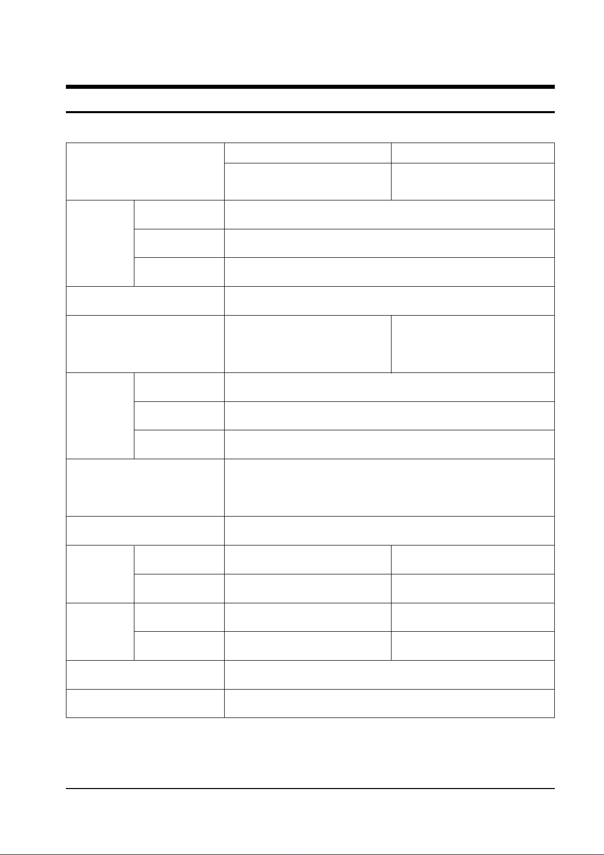
3. Specifications
ST436WM
HLK436W
ST506WM
HLK506W
MODEL
SYSTEM
TUNING
COLOUR
SOUND
Frequency Synthesizer
NTSC 3.58Mhz
Dolby Pro Logic
ANTENNA IMPEDANCE
SCREEN SIZE
Width 973 mm
Length 558 mm
75 ohm Unbalanced Coaxial
Consumption
Requirements
Frequency
POWER
VHF Channel : 2 ~ 13
UHF Channel : 14 ~ 69
CATV Channel : 1,14 ~ 125
TUNING RANGE
15 Watts/CH x 3(R/L/Center Speaker)
SOUND OUTPUT
DIMENSIONS
(W x D x H)
WEIGHT
SET Only
Including Packing
SET Only
Including Packing
1075 x 399 x 755mm
1173 x 497 x 876mm
33Kg
40Kg
PROFILE
TRANSMITTER TYPE
185mm
TM63 47Keys
Width 1130 mm
Length 648 mm
180 Watts ± 20%
AC Input Voltage : 120V
60 Hz
1230 x 450 x 859mm
1337 x 561 x 995mm
38Kg
47Kg
43”
50”

3-2 Samsung Electronics
MEMO
Disassembly and Reassembly
Samsung Electronics 4-1
4. Disassembly and Reassembly
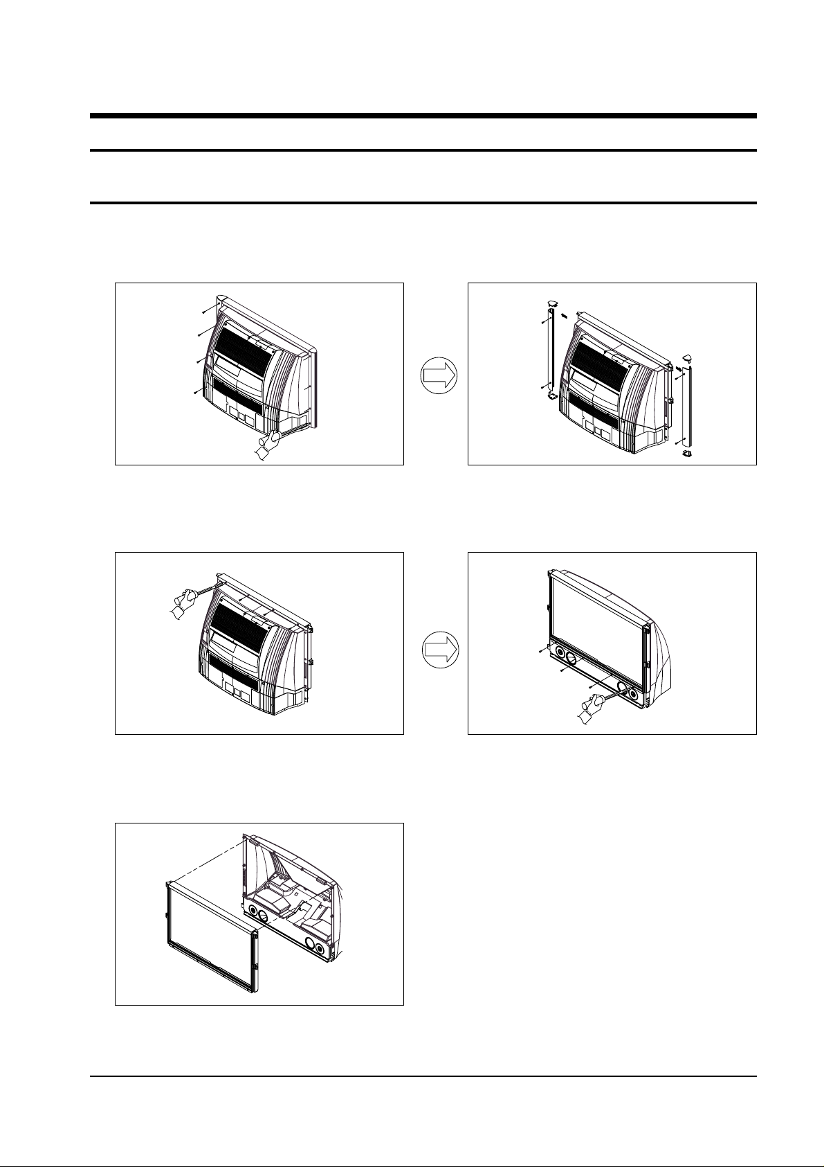
4-1 Back Cover Removal
1. After removing the screws, pull the bottom and side holder part of the cabinet back wards.
2. Loosen the screws and remove the supporter.
4. Loosen the screws. Remove the front mask.
3. After loosening the screws, remove the lens
cover and fan duct.

Disassembly and Reassembly
4-2 Samsung Electronics
4-2 Lamp Replacement
1. Loosen the screw.
3. Using a (+)driver, loosen the screw that secure
the lamp.
2. Remove the cover.
4. Pull out the lamp.
5. PROCEDURE
After completing the lamp replacement, enter the
Service Mode
Press the remote control Keys in the following
sequence:
“Power off ➔ Mute ➔ 1 ➔ 8 ➔ 2 ➔ Power On”
The Service Mode Screen appears in 15 ~ 30
seconds.
(1) Select 11 (Display) with using the joystick
downward, and then select the lamp life
time with using the joysick in the
displayed mode.
(2) Press the Mute key to reset the lamp life
time (“0hrs”).
(3) Press the Power key to save the factory
value.
Disassembly and Reassembly
Samsung Electronics 4-3
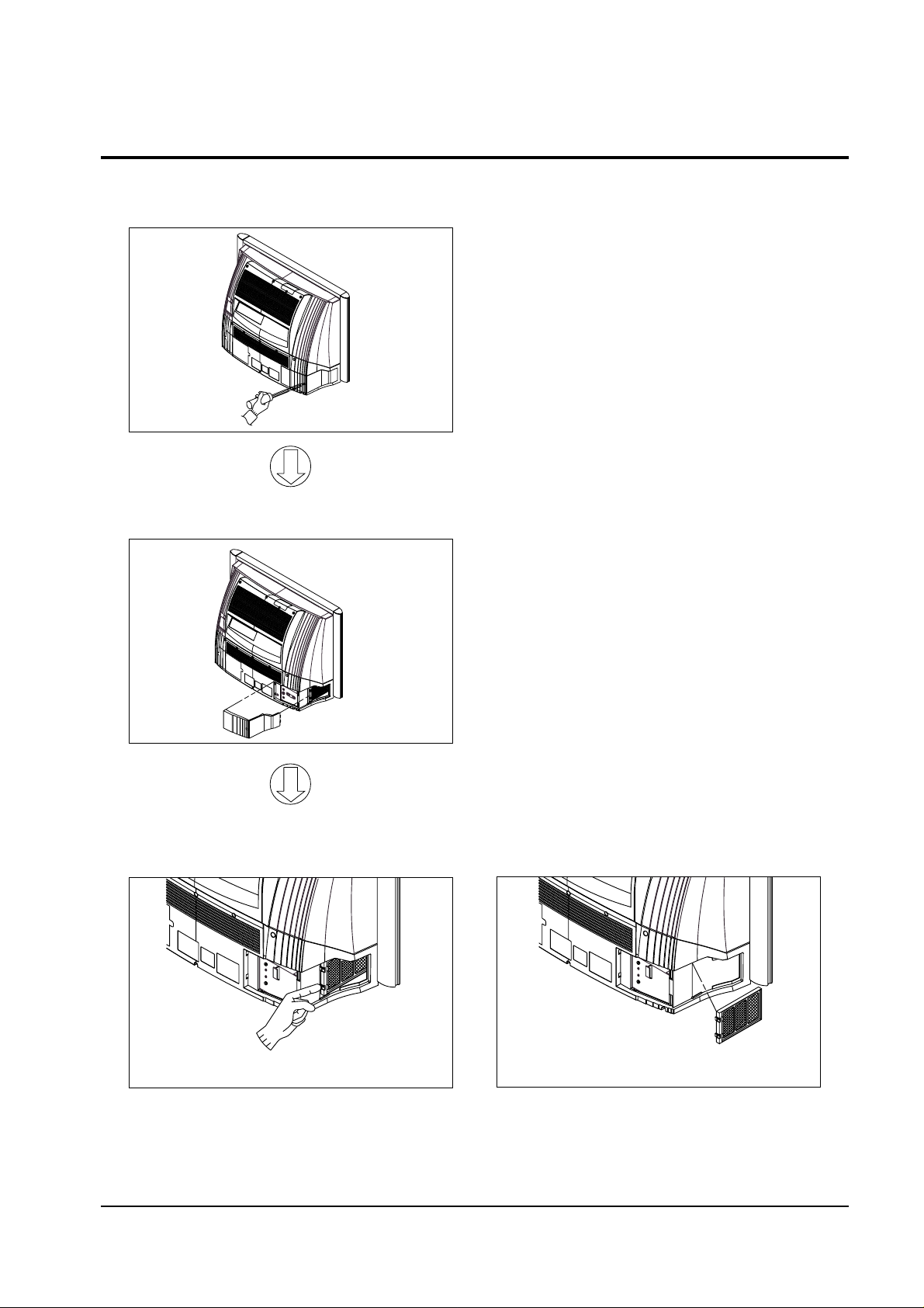
4-3 Air Filter Check
2. Remove the cover.
3. After removing the holder and filter from the
cover, clean the filter.
1. Loosen the screw.

Disassembly and Reassembly
4-4 Samsung Electronics
4-4 FLCD Engine &PCB Replacement
1. After removing the screws, pull the cabinet
backwards.
3. Remove the Case and Loosen the 5 Screws
5. Loosen the screws and pull the PCB upwards.
2. Loosen the 2 screws and remove the air filter
at the right side then pull out the optical
engine.
4. Disjoint the 3FPC connectors and 2 connectors.

Alignment and Adjustments
Samsung Electronics 5-1
5. Alignment and Adjustments
5-1 Lens and Mirror Cleaning
1. Mix the alcohol and ethyl in appropriate proportions.
2. Use a clean cotton cloth or a cleaning paper.
3. Clean the top of the lens by turning it as shown. The pattern starts at the
center and proceeds outward, as shown below:
4. Use minimal pressure when rubbing the mirror. Otherwise, the surface
will be damaged.
5-2 Focus Adjustment for projection Lens
1. Loosen the 1 screw that secures the optical
assembly.
2. After applying the FLCD panel signal, input
a lion head pattern from a pattern
generator.
3. Move the focus adjustment lens right and left
until the FLCD picture element is clearly
displayed on the screen.
4. Reposition the optical assembly, and fasten
1 screw.
6. Check the focus adjustment.
7. Repeat adjustments 1~5, if necessary.
Fig. 5-1
Alignment and Adjustments
5-2 Samsung Electronics
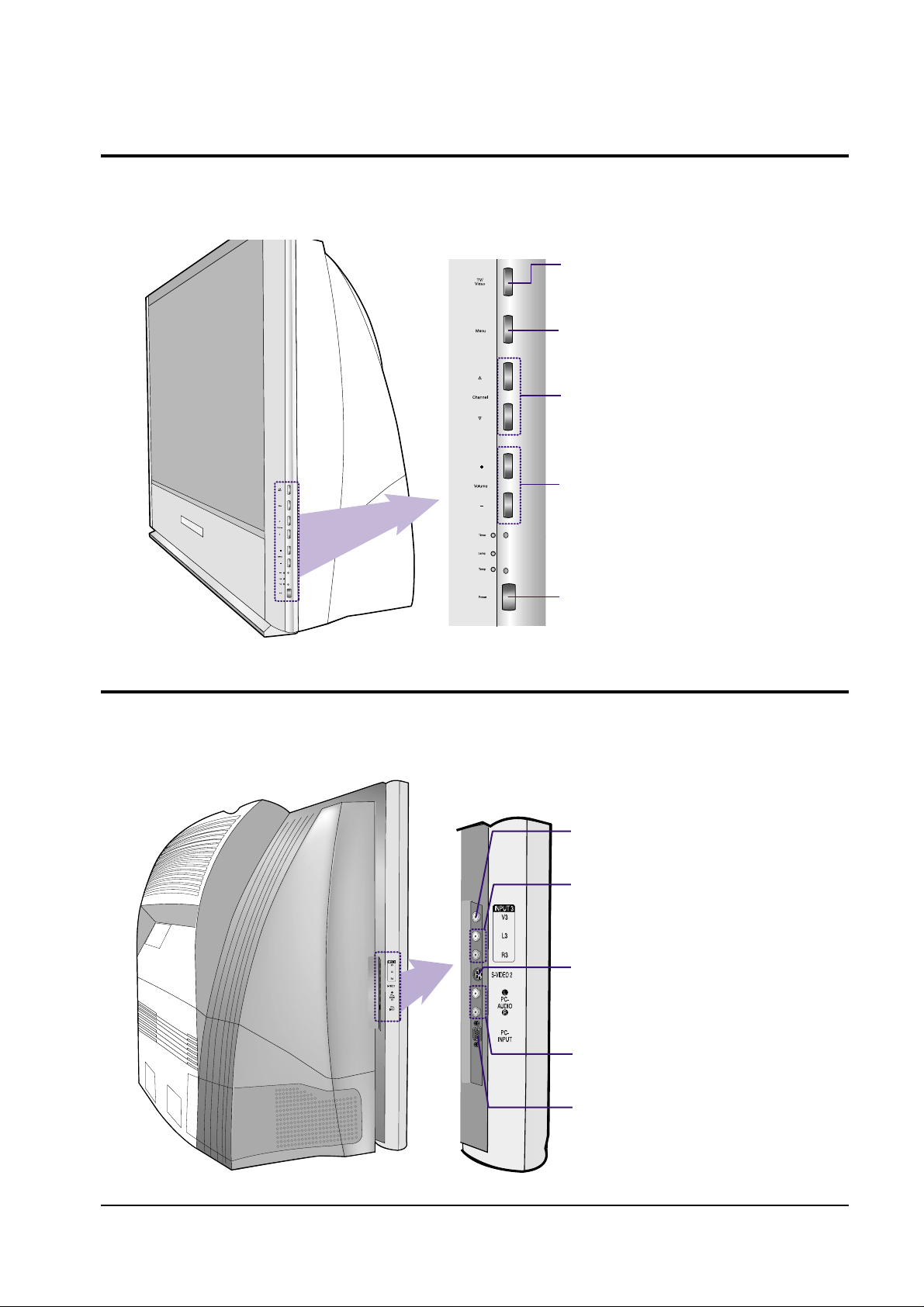
5-3 Side Panel Buttons
The buttons on the side panel control your TV’s basic features, including the on-screen menu
system. To use the more advanced features, you must use the remote control.
TV/Video
Press to display all of the available video sources (i.e., TV,
VCR, DVD, DTV, PC.).
Menu
Press to see the on-screen menu.
▲Channel▼
Press to change channels.
Volume +, –
Press to lower or raise the volume.
Power
Press to turn the TV on and off.
5-4 Side Panel Jacks
Use the side panel jacks to connect a component that is used only occasionally
(a camcorder, video game or PC, for example) .
VIDEO IN JACK
Connect the video signal from a camcorder or video game.
AUDIO IN JACKS
Connect the audio signal from a camcorder or video game.
S-VIDEO IN JACK
Connect an S-video signal from a camcorder or video game.
(S-Video 2 jack and Audio L/R input 3 interlock.)
PC AUDIO IN JACKS
Connect these to the audio-output jacks on your PC.
PC VIDEO IN JACK
Connect to the video output port on your PC.
Alignment and Adjustments
Samsung Electronics 5-3
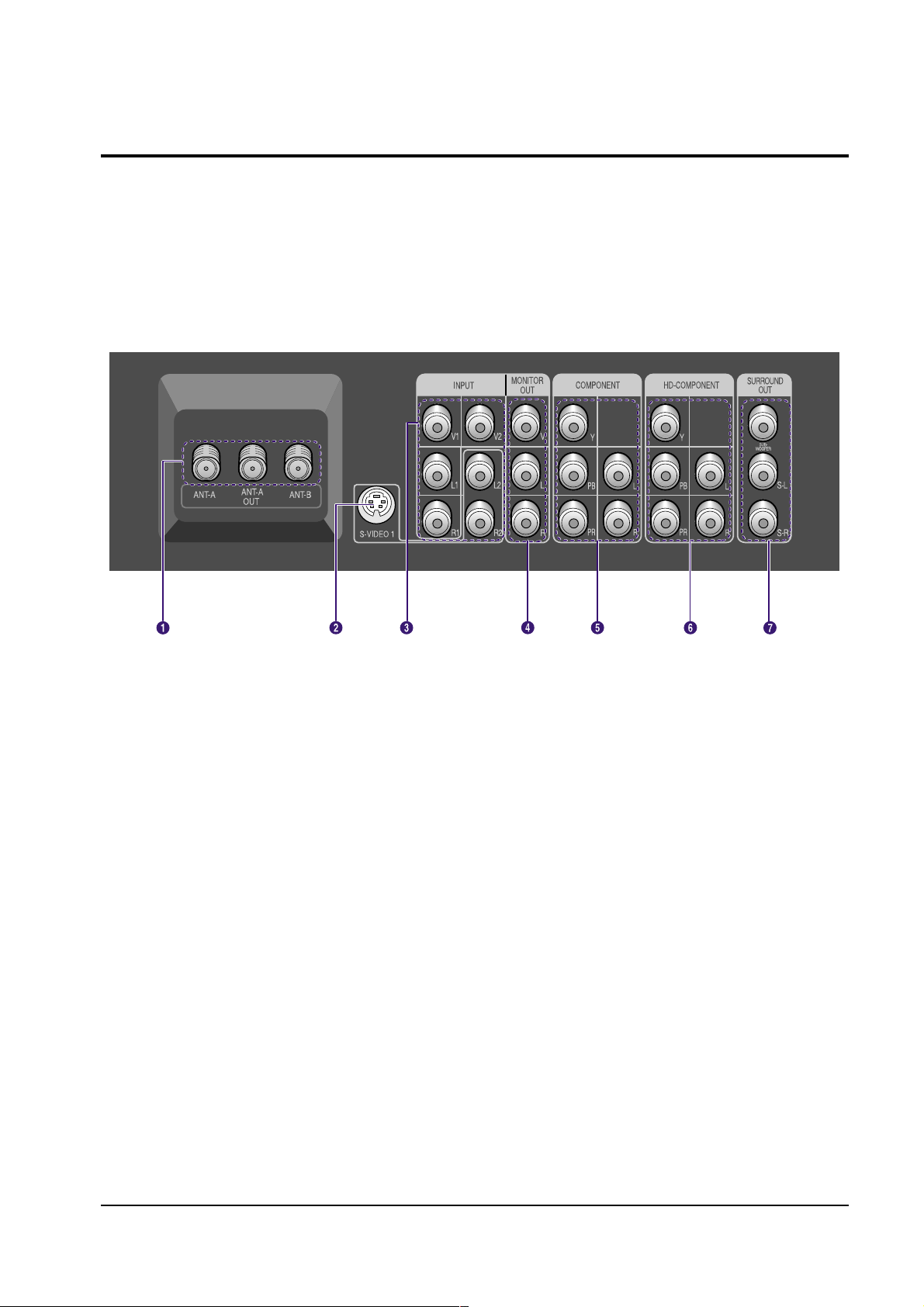
5-5 Rear Panel Jacks
Use the rear panel jacks to connect components such as a VCR or laserdisc player.
You can connect two different components such as two VCRs, a laserdisc player and a DVD player etc., because there
are two sets of video input jacks and one set of component video input jacks on the rear panel of your TV. For more
information, please see “Connections”.
Œ
ANTENNA terminals
Two independent cables or antennas can be connected to these
terminals. Use ANT-A and ANT-B terminals to receive a signal
from VHF/UHF antennas or your cable system. Use the ANT-A
OUT terminal to send the signal being received by the ANT-A
terminal out to another component (such as a Cable Set Top
Box).
The PIP channel can be received only when a signal source is
connected to ANT-A.
´
S-VIDEO IN jack
Connects an S-Video signal from an S-VHS VCR or laserdisc
player.
ˇ
VIDEO INPUT jacks(V1, V2)
Connect video signals from external sources like VCRs orDVD
players.
AUDIO INPUT jacks(L1,R1/L2,R2)
Connect audio signals from external sources like VCRs orDVD
players.
¨
VIDEO MONITOR OUT jack
Sends a video signal from the TV to an external source, such as
a VCR.
AUDIO MONITOR OUT jacks
Send audio signals from the TV to an external source, such as a
VCR.
ˆ
COMPONENT AUDIO INPUT jacks (L, R)
Use these jacks to connect the audio signals from a DVD player
when using the component video input jacks.
COMPONENT VIDEO INPUT jacks (Y, PB, PR)
Use these jacks to connect the component video signals from
a DVD player.
Note: Only 408i format is supported in its original format.
Ø
HD Component (DTV Set Top Box) VIDEO
INPUT jacks (Y, PB, PR)
Receives the DTV video signals (Y/PB/PR) from a Set Top Box.
Note: Only 408p, 720p and 1080i formats are supported in their
original formats.
HD Component (DTV Set Top Box) AUDIO
INPUT jacks (L, R)
Receives the DTV audio signals (L/R) from a
DTV Set Top
Box.
∏
SURROUND OUTPUT jacks
Use to connect a subwoofer and powered rear surround
speakers.

Alignment and Adjustments
5-4 Samsung Electronics
.
5-6 LED Display Check
The three lights on the side panel indicate the status of your TV.
• It takes about 30 seconds for the TV to warm up, so normal brightness may not appear immediately.
• The TV has a fan to keep the inside lamp from overheating. You’ll occasionally hear it working.
: Light is On
: Light is Blinking
: Light is Off
Indicator Light Key
Alignment and Adjustments
Samsung Electronics 5-5
5-7 SERVICE MODE ADJUSTMENTS
1. Factory Mode Items :
1) Adjustment Items
2) Test Pattern
3) Option Table
4) Reset
2. To enter the Factory Mode :
1) Press the factory remote control keys in the following sequence : Display -> Factory
2) Press the user remote control keys in the following sequence :
(In Power Off) Mute ->1 -> 8 -> 2 -> Power On
3) Reset : Disconnect the power cord and connect it again.
3. OSD Display :
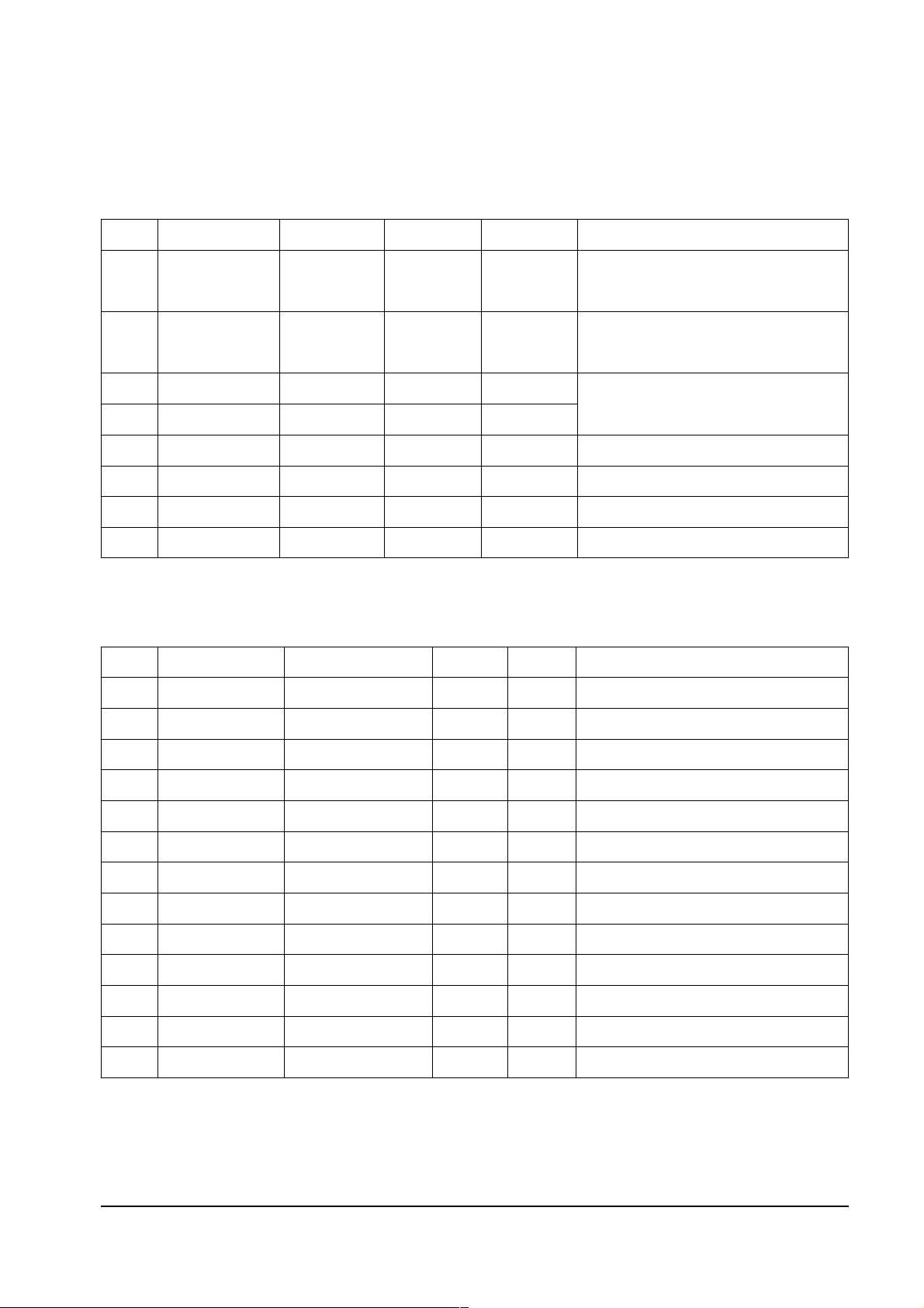
5-7-1 Details of Control
5-7-1(A) PWS364
No Address Item Range Default Description
1 Red Gain Red Gain 0 ~ 255 123 High Light Adjustment (Variable)
2 Green Gain Green Gain 0 ~ 255 91 High Light Adjustment (Variable)
3 Blue Gain Blue Gain 0 ~ 255 135 High Light Adjustment (Fixed)
4 APL On/off APL On/off 0, 1 1 Fixed, Shipment Setting : APL On
1. PW364 9. OSD Position
2. FLCD Driver 10. Window Voltage
3. VPC3230 - RF/Video 11. Display
4. SDA9400 - RF/Video 12. Test pattern
5. CIP3250 13. Option Table
6. CXA2101Q - DTV only 14. Reset
7. AD9884 - DTV/PC
8. PIP control
Help message
Alignment and Adjustments
5-6 Samsung Electronics
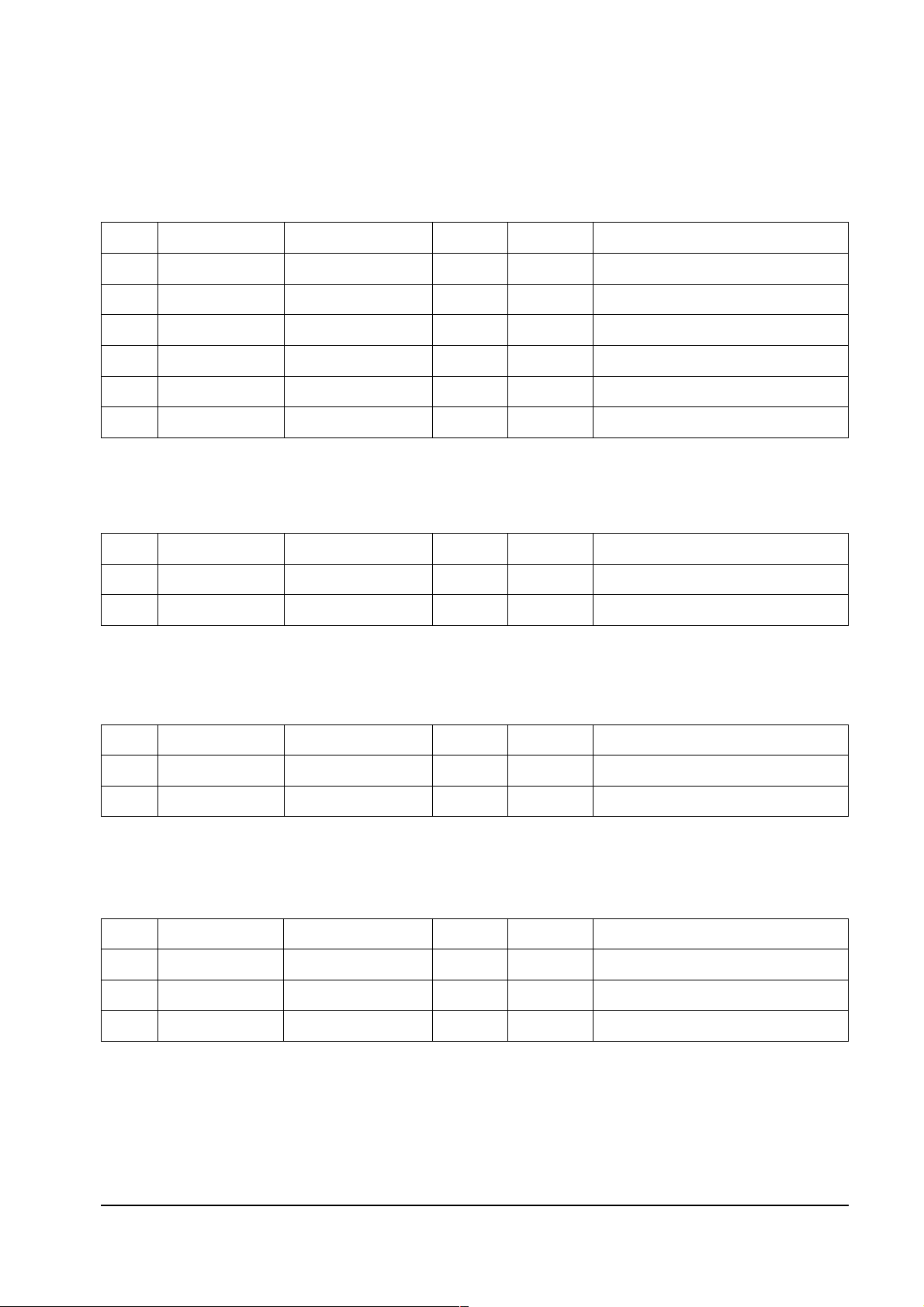
5-7-1(B) FLCD DRIVER
No Address Item Range Default Description
1 H_Position (h02) H-Position 1 ~ 80 30
H-Position
(The Picture moves left when the value
increase)
2 V_Position (h03) V-Position 1 ~ 127 22
V-Position
(The Picture moves up when the value
increases.)
3 V_Shift (h43) V_Shift 0 ~ 255 24
4 Bank_start (h60) Bank_start 0 ~ 255 24
5 PCLK Inv. (h42) PCLK Inversion 0, 1 0 Pixel clock inversion (Fixed)
6 Red Offset Red Cutoff 0 ~ 255 128 Low Light Adjustment
7 Green Offset Green Cutoff 0 ~ 255 128 Low Light Adjustment
8 Blue Offset Blue Cutoff 0 ~ 255 128 Low Light Adjustment
5-7-1(C) VPC3200
No Address Item Range Default Description
1 Bright YUV (h92) Brightness of YUV 0 ~ 255 195 Comp. (DVD) Bright. Level (Fixed)
2 Cont. YUV (h92) Contrast of YUV 0 ~ 63 27 Comp. (DVD) Cont. Level (Fixed)
3 IF Comp. (h21) IF Compensation 0 ~ 3 2 Air IFFrequency Characteristic Setting (Fixed)
4 Chroma band (h21) Chroma Band width 0 ~ 4 3 Chroma Band øµø™ Setting (Fixed)
5 Ena. luma. (h21) Enable Luma. LPF 0, 1 1 Determines whether LPF is used or not (Fixed)
6 HPLL Speed (h21) HPLL Speed 0 ~ 3 0 VCR/Air Sync. Response Velocity Setting
7 Luma Delay (h23) Luma/Chroma Delay 0 ~ 9 5 Y/C Delay
8 3230 Bright. (h52) Brightness 0 ~ 255 155
9 3230 Contrast (h53) Contrast 0 ~ 63 42
10 H LPF Y/C H LPF for Y/C 0 ~ 4 0 By pass, f1, f2, f3
11 H LPF Chroma H LPF Chroma 0 ~ 2 0
12 H Peaking H Peaking Filter 0 ~ 3 2 Broad, Med, Narrow
13 Coaring Off/on Coaring Off/on 0, 1 1 Coring off, on
Set the start point area of the driver data
(The Picture moves down when the value
increase)

Alignment and Adjustments
Samsung Electronics 5-7
No Address Item Range Default Description
1 NR On (h1D) NR On 0, 1 1 Temporal Noise Reduction
2 SNR On (h1D) SNR On 0, 1 0 Spatial Noise Reduction
3 VCSNR On (h1D) VCSNR On 0, 1 0 Vertical Spatial Noise Reduction
4 HCSNR On (h1D) HCSNR On 0, 1 0 Horiz. Spatial Noise Reduction
5 DTNR On (h1D) DTNR On 0, 1 1 Frame / Field Selection
6 TNRCLY (h1E) TNRCLY 0 ~ 15 13
7 TNRCNC (h1E) TNRCLC 0 ~ 15 13
5-7-1(D) SDA9400
No Address Item Range Default Description
1 Bright YUV (h92) Brightness of YUV 0 ~ 255 139 Comp. (PinP) Brightness Level
2 Cont. YUV (h92) Contrast of YUV 0 ~ 63 42 Comp. (PinP) Contrast Level
5-7-1(E) CIP3250

Alignment and Adjustments
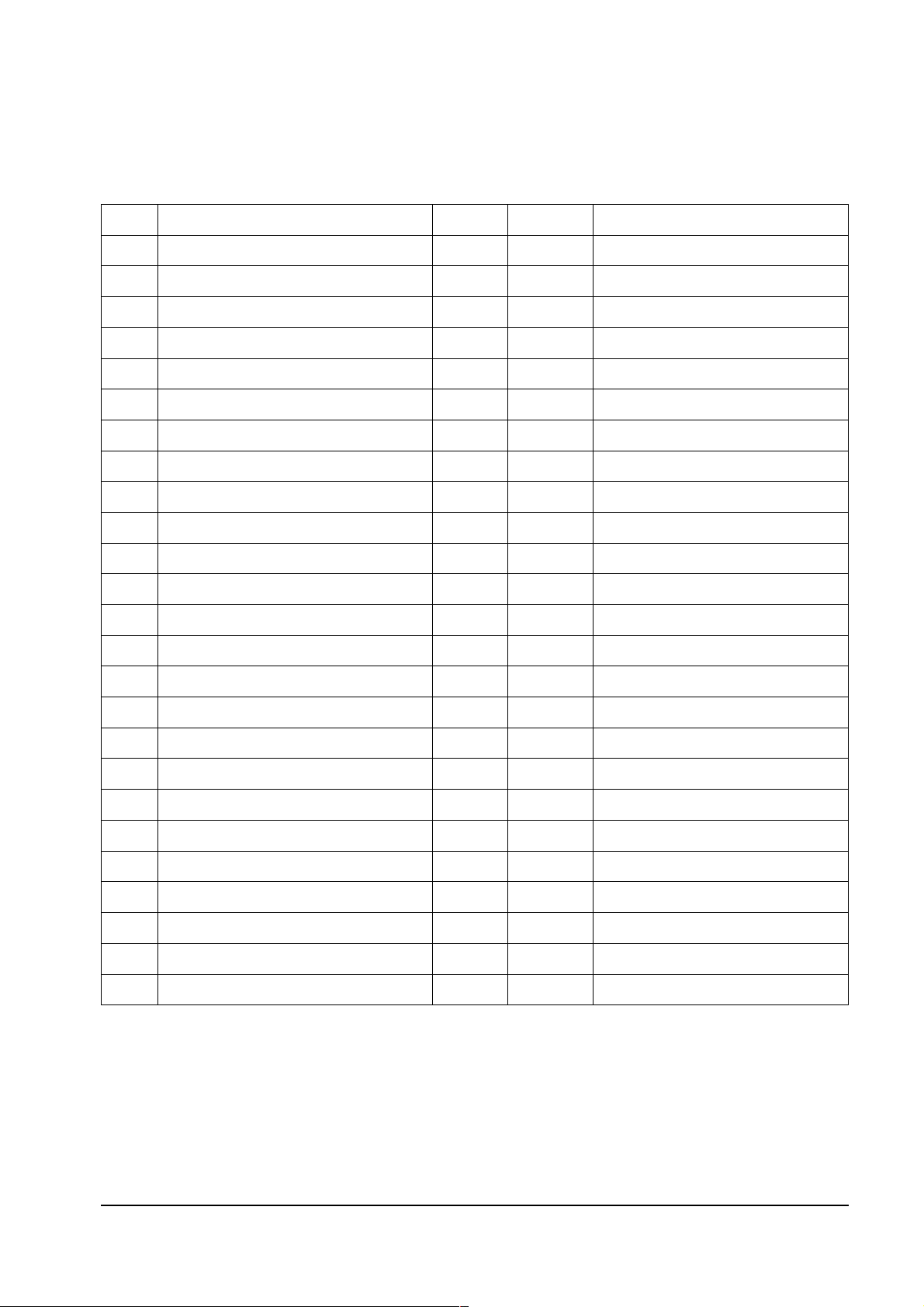
5-8 Samsung Electronics
No Address Item Range Default Description
1 Limit Level (H02) Limit Level 0 ~ 3 0 Limits the input level (Fixed)
2 System (h03) System 0 ~ 3 3 480p, 720p, 1080i
3 D-Color (h07) D-Color 0 ~ 2 1 Dynamic Color
4 R Drive (h07) R Drive 0 ~ 63 32 DTV W/B (Fixed)
5 G Drive (h08) G Drive 0 ~ 63 32 DTV W/B (Fixed)
6 B Drive (h09) B Drive 0 ~ 63 32 DTV W/B (Fixed)
7 R Cutoff (h0A) R Cutoff 0 ~ 63 32 DTV W/B (Fixed)
8 G Cutoff (h0B) G Cutoff 0 ~ 63 32 DTV W/B (Fixed)
9 B Cutoff (h0C) B Cutoff 0 ~ 63 32 DTV W/B (Fixed)
10 ABL Mode (h0A) ABL Mode 0 ~ 3 0 ABL Mode Setting
11 ABL_TH (h0B) ABL-TH 0 ~ 3 0 Voltage
12 H_Sep. Sel (h0D) HSep Sel 0, 1 0 H-Sync. Separation System
13 Fix Sync. (h0E) Fix Sync. 0 ~ 3 0 0 : Auto
14 V Time Con (H0e) V Time Constant 0 ~ 3 1 Set the time constant for V-Sync Seperation
15 H-Width (h0E) H-Width 0 ~ 3 1 H-Sync Width Adjustment
16 HHD time con(h0E) H Time Constant 0, 1 0
17 HS Mask (h0E) HS Mask 0, 1 1
18 Sub Bright (h0D) Sub Bright 0 ~ 63 55
19 Sub Cont (h11) Sub Contrast 0 ~15 7
20 Sub Color (h11) Sub Color 0 ~15 5
21 Sub Hue (h12) Sub Hue 0 ~15 3
22 Sub Shp (h17) Sub Shp 0 ~ 4 3
23 R-Y/R (h13) R-Y/R 0 ~15 2
24 R-Y/B(h13) R-Y/B 0 ~15 2
25 G-Y/R(h14) G-Y/R 0 ~15 4
26 G-Y/B(h14) G-Y/B 0 ~15 13
27 PABL Level (h16) PABL Level 0 ~15 8 Peak ABL
28 SHP F0 (h17) SHP F0 0 ~ 4 2 Sharpenss F0 Selection
29 Pre/over (h17) Pre/over 0 ~ 3 1 0 = Pre. : Over=1:1.3, 3=3:1
30 CTI Level (h12) CTI Level 0 ~ 3 0 C Transition Level
31 LTI LevelL (h17) LTI Level 0 ~ 3 0 Y Transition Level
32 DC-Tran (h18) DC-Tran 0 ~ 3 1 Y DC Transmission Rate
33 D-Pic (h18) D-Pic 0 ~ 3 0 Dynamic Picture
5-7-1(F) CXA2101
Alignment and Adjustments
Samsung Electronics 5-9
No Address Item Range Default Description
1 Red Gain (h02) Red Gain 0 ~ 255 135 PC Mode W/B (Fixed)
2 Green Gain (h03) Green Gain 0 ~ 255 135 PC Mode W/B (Fixed)
3 Blue Gain (h04) Blue Gain 0 ~ 255 135 PC Mode W/B (Fixed)
4 Red Offset (h05) Red Offset 0 ~ 63 32 PC Mode W/B (Fixed)
5 Green Offset (h06) Green Offset 0 ~ 63 32 PC Mode W/B (Fixed)
6 Blue Offset (h07) Blue Offset 0 ~ 63 32 PC Mode W/B (Fixed)
5-7-1(G) AD9884
No Address Item Range Default Description
1 PIP HPos PIP HPos 0 ~ 63 20 PinP Horizontal Position
2 PIP VPos PIP VPos 0 ~ 63 20 PinP Vertical Position
5-7-1(H) PIP CONTROL
No Address Item Range Default Description
1 Horiz Horiz (Left, Right) 8 ~ 104 40 Move 8 by 8 (Total :12 Step), Fixed
2 Vert Vert (Up, Down) 8 ~ 40 13 Move 8 by 8 (Total :12 Step), Fixed
5-7-1(I) OSD POSITION
No Address Item Range Default Description
1 RV Win RV Win 31 0 ~ 63 31 Display Check Only (No Touch)
2 GV Win GV Win 31 0 ~ 63 31 Display Check Only (No Touch)
3 BV Win BV Win 31 0 ~ 63 31 Display Check Only (No Touch)
5-7-1(J) WINDOW VOLTAGE

Alignment and Adjustments
5-10 Samsung Electronics
No Item Range Default Description
1 Lamp Life Time - - Indicate total elapsed time
2 Red Panel Temperature - - Displays R Panel temperature
3 Green Panel Temperature - - Displays R Panel temperature
4 Blue Panel Temperature - - Displays R Panel temperature
5 Environment Panel Temperature - - Display Environment Temperature
5-7-1(K) DISPLAY
Alignment and Adjustments
Samsung Electronics 5-11
No Item Range Default Description
1 Crosshatch 00001 2 White Window 00010 -
3 Black Window 00011 4 Color Bar 00100 5 Black White Black White 00101 6 Horizontal Ramp 00110 7 Vertical Ramp 00111 8 White 100% 01000 - Contrast 100%, Contamination check
9 White 70% - Contrast 100%, Contamination check
10 White 50% - Contrast 100%, Contamination check
11 White 30% - Contrast 100%, Contamination check
12 White 10% - Contrast 100%, Contamination check
13 Yellow 01001 -
14 Margenta 01010 15 Cyan 01011 16 Green 01100 17 Red 01101 18 Blue 01110 19 Black 01111 -
20 Small White Window 10000 21 Small Black Window 10001 22 4 X 4 Black Window 10010 23 Horizontal Black White 10011 24 Vertical Black Window 10100 25 Gray Pattern 10101 -
5-7-1(L) TEST PATTERN

Alignment and Adjustments
5-12 Samsung Electronics
5-7-1(M) OPTION TABLE
No Item Default Description
1 MPX on
off :MPX Mode is Automatic Setting Mode
on : MPX Mode is User Setting Mode
2 Image Inversion off
off : normal
on : Inversion
3 Auto Power off
Off
On
4 Time on Video on
off : RF mode
on : last video mode is displayed
5 Picture Size on
off : Wide
on : last display mode is displayed
6 Frame Lock on
on: Frame Locked
off : Frame Unlocked
7 Remocon Pin 28 -
 Loading...