

Page 1

Multi Media Functions/Equipment
Media Player
You can play video and audio CD files with the Windows Media Player, as well as
watching TV, video and listening to the radio through internet. The on-board audio
hardware and software of your computer enable the computer to play audio/video
compact discs. The instructions to play a video CD-ROM are the same as the
instructions for the audio CD below. If you wish to do so, you can attach external
speakers to the Headphone jack.
Playing a Audio/Multimedia CD
To play an CD follow the instructions below:
1. Insert a compact disc into your CD-ROM drive.
2. Press the button on the CD-ROM drive to open the CD-ROM device.
3. Insert a CD, label side up.
4. Carefully push the tray in to close the drive tray. The Windows Media Player
button appears on the taskbar if not already there, and the music begins to play. If
the disk does not play click Start > Programs > Accessories > Entertainment >
Windows Media Player.
CD LED On:
A LED on the drive tray is on when the computer is reading from a CD. Do not
remove a disc when this LED is on.
Removing the Audio/Multimedia CD
To remove the CD follow the instructions below:
1. Click Start > Programs > Accessories > Entertainment > Windows Media
Player to open the Windows Media Player window, if not already open.
2. Click Stop in the Windows Media Player window or simply close the Windows
media player.
3. Press the button on your CD-ROM drive. The drive tray opens and you can remove
the CD from the CD-ROM drive.
4. For more information on playing compact discs, see the Help menu in the
Windows Media Player window.
Multi Media Functions/Equipment 33
Page 2
Dolby Digital & Dolby Theater System
Your computer supports Dolby Digital & Dolby Theater System through a SPDIF
connector, located next to the volume control wheel on the left side of the computer.
You must have a 3.5 mm (mono)- to RCA cable to use this port.
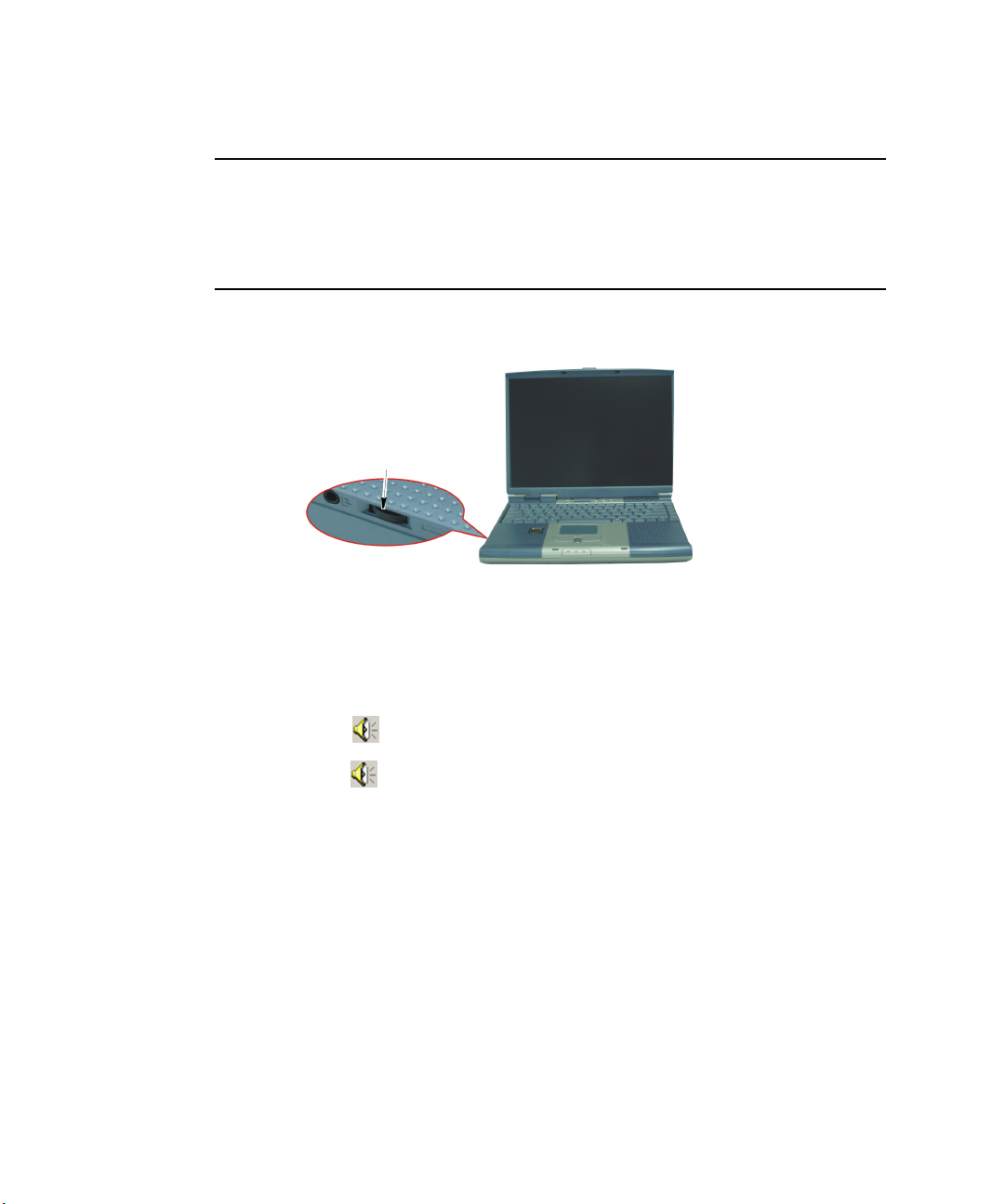
Volume Control
Using the Wheel Volume Control
Simply turn the wheel located on the left side of the computer.
Wheel Volume Control
Using the Keyboard
Changing the volume with your keyboard.
Use <Fn+F9> to decrease the volume or <Fn+F10> to increase the volume.
Using the Volume Control Icon
Double-Click icon in the active program tray. The Volume Control window pops
up. Use this window to adjust the volume. You can pop up a simple volume slider by
a single click icon.
34 Users Manual
Page 3

Using the Battery
Your computer uses a smart rechargeable Lithium-ion (Li-ion) battery pack for power
when the AC adapter is not attached to an electrical outlet. The smart battery gives a
accurate measurement of the current battery capacity which helps extend operating
time by enabling effective power management in operating systems that take
advantage of the accurate information supplied by the battery.
Charging the Battery
Your computer’s battery starts charging automatically when you connect the power to
the computer and to an electrical outlet. If the computer is off, the battery charges faster
than if the computer’s power is on.
Approximate charging times for the Li-Ion battery are
• 3 hours with the computer off.
• 6 hours with the computer on.
While the battery is charging normally, the battery charge light on the computer is red.
When the battery is fully charged, the light changes to green.
When you use a new battery pack for the first time or use a battery after a long period
of storage, the initial battery life is shorter than normal. Normal battery life resumes
after a few discharge-recharge cycles.
Follow these rules for charging your battery:
• A battery normally discharges power when not used for long periods of time.
Be sure to recharge the battery every two months when it is not in use.
• Make it a practice to discharge your battery fully before recharging the battery.
This can help extend the life of the battery.
• Do not attempt to charge the battery in temperatures of under 5
o
C or over 35oC
All batteries eventually wear out and lose the ability to hold a charge. You may
need to replace your battery pack after a year of average usage.
Using the Battery 35
Page 4
Safely Using the Battery
Follow these guidelines to safely use the battery:
• Turn off your computer and unplug it if you accidentally:
– Expose the equipment to liquid.
– Drop, jar, or damage the computer.
• Use only approved battery chargers.
• Do not disassemble the battery, heat it above 100°C, or burn it. The battery
used in this computer may cause a fire or chemical burn if mistreated.
• Your computer's rechargeable battery may be considered hazardous waste. If
you replace your battery with a new one:
– Keep the old battery out of the reach of children.
– Dispose of the old battery promptly.
– Make sure that you follow all local requirements when you dispose of the
old battery.
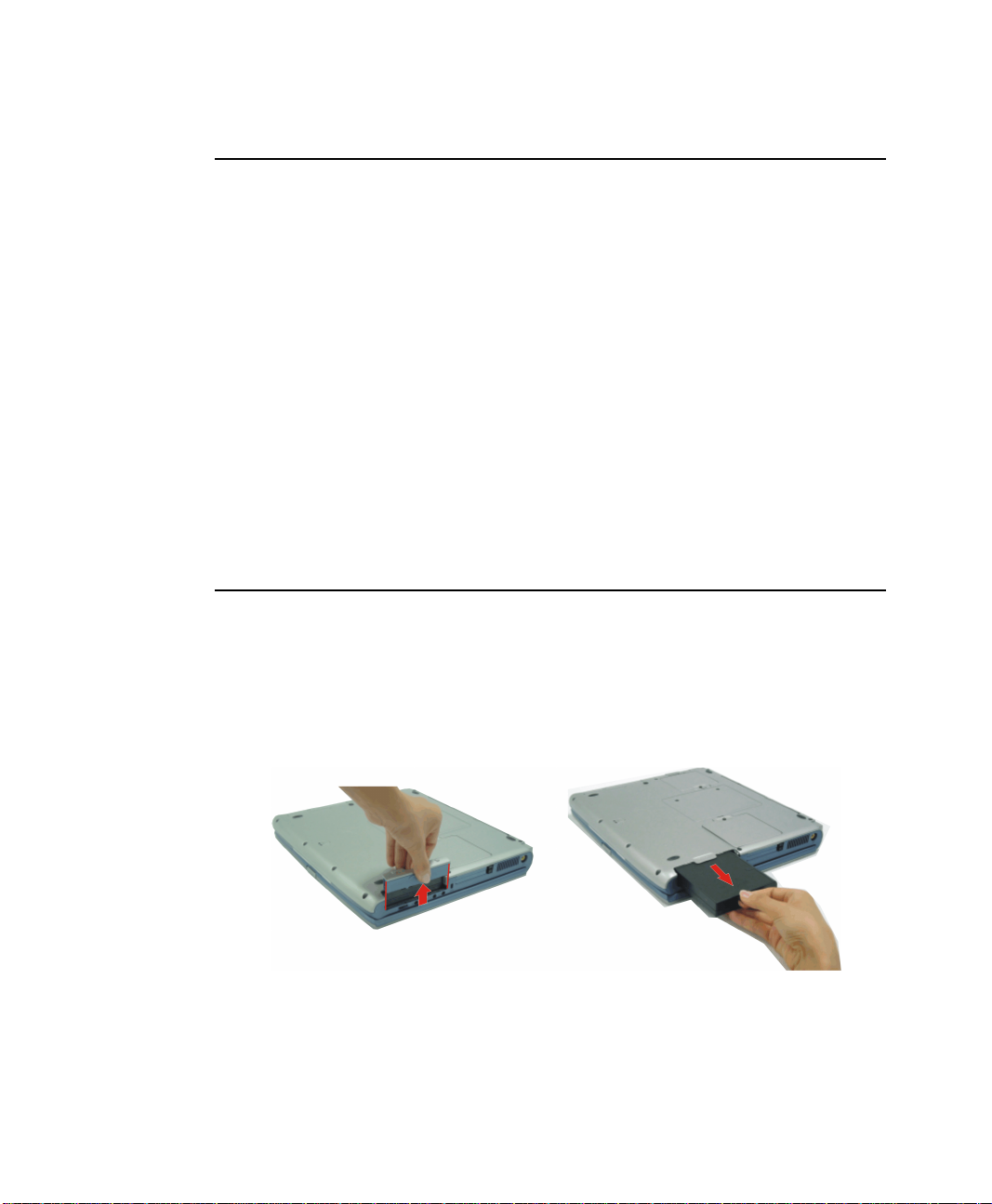
Removing the Battery
Your computer comes with the battery pack inserted in the computer.
To remove the battery from the computer:
1. Turn the computer’s power off.
2. Close the LCD panel, and turn the computer over so that the bottom of the unit
faces up.
3. Slide the battery compartment cover straight up and off the computer.
4. Grasp the tab on the battery and pull the battery out of the compartment.
36 Users Manual
Page 5
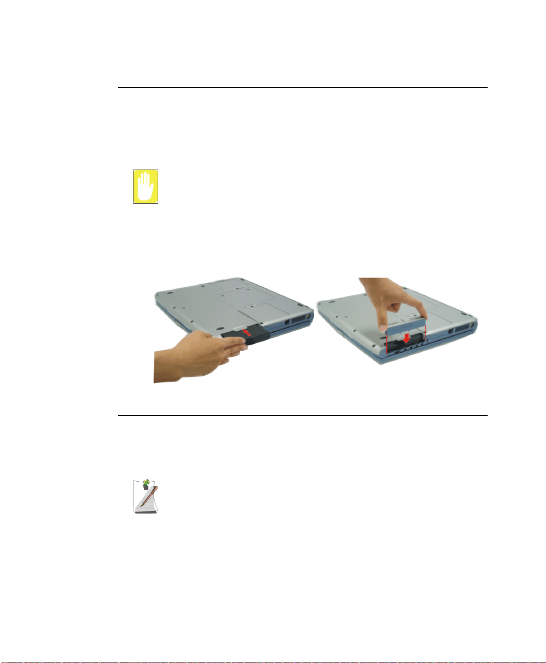
Installing the Battery
To install the battery pack:
1. With the computer’s power off, close the LCD panel and turn the computer over
so the bottom of the unit faces up.
2. Slide the battery compartment cover straight up and off the computer.
Insert the battery into the battery compartment, ensuring the correct
orientation so that the battery fits in its slot properly.
3. Slide the battery pack into the compartment. Make sure the battery is fully inserted
into the compartment.
4. Align the tabs on the battery compartment cover with the slots on the battery
compartment.
5. Push the cover straight down until it snaps into place.
Monitoring the Battery Charge
Battery life is affected by factors such as the power-management settings in System
Setup, the applications you use, and the brightness settings of the LCD. Under normal
usage, the battery charge lasts approximately 3 hours.
Battery life estimates are subject to variation. The actual life of your battery
may be less than the estimates given in the manual.
You can monitor the charge of the battery pack installed in your computer by using the
Power Meter or Battery Gauge.
Using the Battery 37
Page 6
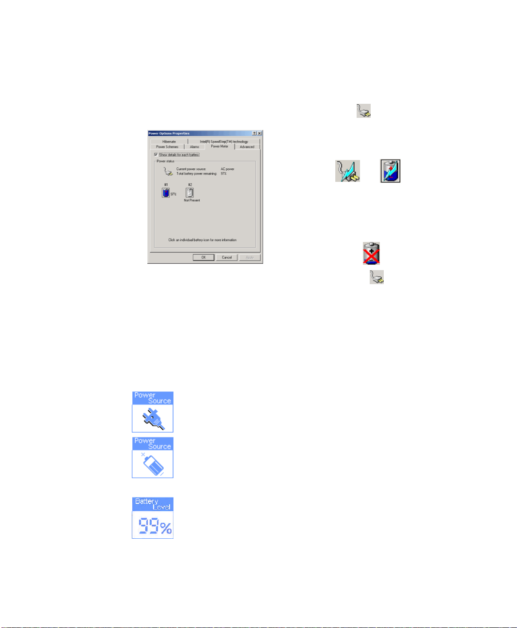
Power Meter
The Power Meter displays the charge of the batteries and the current source of
computer power, AC or batteries. You may monitor the battery charge or usage by
using the “Power Meter”. To access the power meter click icon on the task bar or
click Start > Settings > Control Panel > Power Options > Power Meter Tab.
The Power Status icons shown below are displayed
during Battery Charging Operations
At ~15% and 10% remaining battery power the
current power source and the battery Icons
respectively change to the icon shown below and
you should follow the instructions in “Battery
Warnings” section below
You may also check battery charge by moving the cursor to the icon, a small dialog
box will display the % of charge.
Battery Gauge
You may display the battery gauge while you are in any program by pressing <Fn+F6>.
While the battery gauge is being displayed, all keys except <Esc> are disabled. The
battery gauge is only displayed for a few seconds.
Power Source:
Battery Level:
38 Users Manual
• Indicates that the computer is powered by the AC adapter.
• Indicates that the computer is powered by the battery.
• The top/right section indicates the approximate amount of the
primary battery charge remaining.
Page 7

Battery Warnings
If the battery charge is low (about 10%) you have approximately 5–10 minutes of
battery life left. You should:
• Save your work and,
• Connect the power cord to the computer or turn off the computer and install a
fully charged battery.
You can adjust the battery alarm features by using the operating systems power
management program (Start > Settings > Control Panel > Power Options > Alarm
Tab in Windows).
If you cannot run your computer from the battery and the battery will not charge when
you attach the power cord, the problem may be that:
• The battery temperature is below 10°C or over 32°C. If you think the battery
temperature is too hot or too cold, turn off the computer, remove the battery,
and let the battery reach room temperature. Then try charging the battery again.
• The battery is defective. Replace the battery with a new battery.
Battery Calibration
Calibrating your battery once a month is one of the recommended methods of
increasing your computer’s battery life. To calibrate the battery complete the following
steps:
Calibration Notes:
You should start the battery calibration process with a fully charged battery,
battery status LED is green. The power meter may not show 100%.
Before you commence the battery calibration process you should fully charge,
then fully discharge and finally fully recharge the battery again.
1. Disconnect the AC power adapter after turning off the system.
2. Restart your computer and press <F2> to enter BIOS setup.
3. Using the arrow keys, highlight Battery Calibration in the Power menu.
4. Press Enter to start calibration process. The calibration usually takes 2 to 3 hours
depending on the current battery charge.
5. When the calibration process is complete, recharge the battery fully.
Using the Battery 39
Page 8

Using System Setup
The System Setup program enables you to configure your computer hardware and set
security and power-savings options. The settings you choose are stored in batterymaintained CMOS memory that saves the information even when the computer’s
power is turned off. When your computer is turned back on, it is configured with the
values found in this memory.
Run System Setup if you get a message prompting you to run the program. You may
also want to run System Setup, particularly the first time you use your computer, to set
the time and date, use security or power-management features, or alter the settings of
other features.
Your computer’s version of System Setup may not include all the fields listed
here or may include additional fields. Field names and order of appearance
can vary according to the version of the BIOS (basic input/output system) on
your computer.
Starting System Setup
To start System Setup, turn on your computer and then press <F2> when prompted.
The System Setup screen appears.
The top of the System Setup screen has a menu bar with the selections listed in Table 5.
Table 5. System Setup Menus
Menu Function
Main Changes the basic system configuration.
Advanced Configures advanced features on your computer.
Security Enables security features, including passwords and
Power Configures power-management features.
Boot Specifies the order of boot devices and configures boot
Exit Specifies how to exit System Setup.
backup and virus-check reminders.
features.
To open a menu, use the left or right arrow keys to select the menu name and then press
<Enter>.
40 Users Manual
Page 9

Table 6. System Setup Navigation Keys
Navigation Key Alternate Key Function
<F1> <Alt+H> Displays the General Help window.
<Esc> Exits the current menu.
<Left Arrow> and
<Right Arrow> keys
<Up Arrow> and
<Down Arrow>
keys
<Tab> Moves the cursor forward through the cells for a highlighted
<Tab+Shift> Moves the cursor backward through the cells for a highlighted
<Home> <PgUp> Moves the cursor to the field at the top of the window.
<End> <PgDn> Moves the cursor to the field at the bottom of the window.
<F5> <-> Scrolls backwards through the options for the highlighted field.
<F6> <+> or <Space> Scrolls forward through the options for the highlighted field.
<F9> Sets the parameters for the current menu to their default
<F10> Sets the parameters for the current menu to their previous
<Enter> Executes commands or opens a submenu.
Keypad arrow
keys
Keypad arrow
keys
Select a different menu. Pressing <ESC> at the Main menu
brings you to the Exit menu.
Move the cursor up and down between fields.
field.
field.
values.
values.
Using System Setup 41
Page 10

Changing Booting Priority
The Boot menu in System Setup enables you to select the booting device and to set
booting options.
Boot Device Priority field enables:
You to select the order in which the computer attempts to boot from different devices.
The field has three (3) options: CD-ROM Drive, Removable Devices and Hard
Drive.
To change the booting device priority, choose the device positions by completing the
following:
1. At startup, press <F2> to open System Setup
2. Use <Right Arrow> or <Left Arrow> to select the Boot menu.
3. Press <Enter> in the Boot Device Priority field.
4. Highlight the option with the <PgUp> or <PgDn> keys.
5. Use <-> or <+> keys to move the boot device up or down in the list of options.
6. Press <Esc> to return to the Boot menu.
7. Press <Esc> to go to the exit menu.
8. Select Exit Save Changes, press <Enter>.
9. Press <Enter> again to restart the computer.
If you want to start the system using a bootable CD, change the CD-ROM
Drive to be the first priority and make sure that Auto is set in the Type field of
the Secondary Master Submenu at Main page.
42 Users Manual
Page 11

Using System Security
This section describes your computer security programs. The first is the standard BIOS
security which is standard on almost all computers. The second is a advanced factory
option Biometric security system that uses your fingerprint(s) to control access to your
computer and individual files if necessary. You no longer have to worry about
passwords being lost, stolen or forgotten.
Bios Security
The BIOS security operations are explained below:
System Passwords
The computer provides two levels of password security: administrative-level
(supervisor) and user-level (user). Either password prevents unauthorized access to the
computer. The supervisor password enables full access to all System Setup fields. The
user password enables full access to only the Set User Password and Password on boot
security fields and read access to all other System Setup fields.
If multiple users have access to the computer (such as in a network environment), a
supervisor password can prevent unauthorized access to certain security options.
Choose the type of password security that is appropriate for your work. If you want to
set a user password, you must set a supervisor password first.
If You Forget Your Password
It is very important that you do not forget your password. If you do, you cannot access
your system. Write your password down and keep it in a safe place. If you do forget
and cannot find the written note, please contact the Samsung Helpline. Please have
your receipts available to verify the type and model of your computer. You may be
charged for password removal.
Creating a Password
To create a password:
1. At startup, press <F2> to open System Setup.
2. Use the <Right Arrow> key to select the Security menu.
3. Use the <Down Arrow> key to select Set Supervisor Password or Set User
Password.
4. Press <Enter>. The Set Password dialog box appears.
Using System Security 43
Page 12

5. Type a password of up to seven characters. You can enter letters or numbers, but
you cannot use the function keys, such as <Shift>. Your computer does not
distinguish between capitalized and lowercase letters in your password. As you
type the password, the cursor moves but your password does not appear on the
screen.
6. Press <Enter> after you have typed your password. The computer prompts you to
reenter your password for verification.
7. Type your password again and press <Enter>. A message appears telling you that
the changes have been saved. Press <Enter> again to return to the Security menu.
8. Press <Esc> to go to the Exit menu.
9. Select Exit Saving Changes, press <Enter>, and press <Enter> again to restart the
computer.
Deleting a Password
To delete the password:
1. At startup, press <F2> to open System Setup.
2. Type your password when prompted and press <Enter>.
3. Use the <Right Arrow> key to select the Security menu.
4. Use the <Down Arrow> key to select Set Supervisor Password or Set User
Password.
5. Press <Enter>. The computer prompts you to enter the current password.
6. Press <Enter>. The computer prompts you to enter a password. Do not type
anything.
7. Press <Enter>. The computer prompts you to re-enter the password. Do not type
anything.
8. Press <Enter>. A message appears telling you that the changes have been saved.
Press <Enter> again to return to the Security menu.
9. Press <Esc> to go to the Exit menu.
10. Select Exit Saving Changes, press <Enter>, and press <Enter> again to restart the
computer.
Requiring a Boot Password
After you create a supervisor or user password, you can enable the computer to prompt
for a password each time it starts.
To enable the prompt, select the option Enabled in the Password on boot field in
System Setup. For more information about the Password on boot field.
44 Users Manual
Page 13

Biometric Security
The factory optional fingerprint sensor provides unique security access to your
computer. You will no longer have to worry about losing or forgetting your password.
Since every person has a unique set of fingerprints, only a biometrically enrolled
person may have access to your computer.
Advantages of Biometric Security are:
• Very high level of security
• No password to remember, lose or have stolen.
• Streamlined logon process.
• Single fingerprint will access many programs, eliminating passwords.
If you purchased the Biometric Security option, please refer to the manual provided for
installation and use.
Using System Security 45
Page 14

Using Power Management Options
Your computer includes Power Management options that can help the battery charge
last longer and extend the life of the battery. Power-management options will slow
down or shut off system components when the components are not being used.
Power management may slow down system performance. Your computer runs fastest
with the power cord attached, when power management is disabled.
In the next sections, basic and advanced methods of power management will be
discussed.
Intel® SpeedStep™
Intel® SpeedStep™ will control the CPU speed on your system according to the kind
of power supply as part of power saving management.
To use this function, your system must meet the conditions below:
• Intel SpeedStep Applet Support
• BIOS and OS Support
46 Users Manual
Page 15

Basic Power Management Schemes
This section discusses the basic schemes of power management when the computer is
operating on battery power or using AC power.
Standby vs. Hibernation
Standby unlike hibernation mode does not store unsaved information on your
hard disk; it's stored only in the computer memory. If there is an interruption in
power, the information is lost. So before putting your computer on standby,
you should save your files.
Changing Devices:
Do not change PC Cards while in standby or hibernate modes.
To enter the power management window complete the following:
1. Click Start > Settings > Control Panel.
2. Click Power Options icon to display the Power Options Properties window.
3. Click the Power Schemes tab to display the basic power management options.
Power Schemes Tab
4. Select the time that you wish each of the following actions to occur in Battery and
AC power mode.
• Turn off monitor:
• Turn off hard disks:
• System standby:
• System hibernates:
Using Power Management Options 47
Page 16

Turning off the monitor and HDDs will save a substantial battery power, therefore
when in battery only mode select the shortest time practical.
a Hibernate Mode (Power Management or Manual Method)
When hibernation is used, your computer turns off and when you power up again,
everything is restored exactly as you left it—including programs and documents
you may not have saved or closed. Everything in memory gets saved to the HDD,
and the monitor and hard disk get turned off.
Frequent Interruptions:
If you experience frequent interruptions, you might also consider putting your
computer into automatic hibernation after a specified number of minutes using
the power management options.
a Standby Mode (Power Management or Manual Method)
Standby is used mainly for conserving battery power in your notebook computer. It
also gives you the benefit of getting right back to your work without waiting for the
computer to restart. Standby turns off your monitor and hard disks, placing your entire
system in a low-power state. When you return to your computer, restores your desktop
exactly as you left it. It is recommended that you do not enter standby mode with less
than 20% battery power.
5. Click OK to set your power management options and close the window.
Rest Key:
The manual <Fn + F11> key combination will not activate Standby or
Hibernate modes whilst you are playing a multimedia program or have an
active USB device connected.
48 Users Manual
Page 17

Advanced Power Management Schemes
This section discusses the advanced power management schemes. There are two
buttons that you can use to manually conserve power.
To enter the power management window complete the following:
1. Click Start > Settings > Control Panel.
2. Click Power Options icon to display the Power Options Properties window.
3. Click the Advanced tab to display the advanced power management options.
Advanced Tab
Power & Sleep Button
Programming Windows
4. Select the mode (Standby/Hibernate/Power Off) assigned to the Power button
and/or Rest <F11> key.
The "Rest" key is assigned to the <Fn+F11> key combination.
See “Basic Power Management Schemes” on page 47 for meaning of
Standby and Hibernate modes.
5. Click OK to set your power management options and close the window.
You can return to normal operation after you have used one of the “Power
Management” buttons by quickly pushing and releasing the Power button.
Using Power Management Options 49
Page 18

Using the Hard Drive
Your computer includes a removable IDE (integrated drive electronics) hard drive. The
IDE hard drive can store the data and programs your computer uses. The drive plugs
into a connector on the system board.
The hard drive that comes with your computer has already been formatted. Do
not format the hard drive. Doing so destroys all data contained on the drive. If
you need to format a new drive, or want to erase all data on your existing hard
drive, refer to the manual for your operating system.
Removing the Hard Drive
To prevent loss of data and damage to the disk, do not remove the hard drive
while the computer’s power is on and do not drop or jar the hard drive.
To remove the hard drive from the computer:
1. If you are installing a new hard drive, backup the application and data files on the
old hard drive before removing it from the computer.
2. Turn the computer’s power off.
3. Close the LCD panel, and turn the computer over so that the bottom of the unit
faces up.
4. Remove the screw that holds the hard drive in place.
5. Pull the hard drive out of the computer.
50 Users Manual
Bottom of computer
Hard-drive
Page 19

Installing a Hard Drive
To install a hard drive:
1. Remove the old hard drive from the computer as described in the previous section.
2. Slide the new drive into the hard drive compartment. Make sure the drive is pushed
back as far as it will go.
3. Install the screw that holds the hard drive in place.
4. If required install windows and appropriate device drivers according to the
instructions below.
(Re)Installing Windows and Device Drivers
Use System Recovery CD to (re)install OS and System Software CD to (re)install
device' drivers.
The System Recovery CD is used to (re)install the OS and System Software
to a new HDD or recover from a system crash.
Notebook computers that ship from the factory include System Recover CDROM and System Software CD-ROM, which contains a copy of the
applications and drivers needed for computer's operating system.
In the unlikely event that programs on the computer hard drive become
corrupted or are erased, you can use the System Recovery CD-ROM to
reinstall your operating system and then System Software CD-ROM to
reinstall your original applications and drivers.
Using the Hard Drive 51
Page 20

Video Features and Configuration
Your computer includes a TFT LCD or active-matrix display. The capabilities of the
screen plus the video drivers installed on the computer determine the quality of the
image your LCD can display.
The following sections describe the display capabilities of your computer.
Resolution and Colour Depth
The resolution of the LCD is the sharpness of the image it can display. Resolution is
measured by the number of pixels (individual dots) displayed on the entire screen. In
general, the more pixels the LCD can display, the better the image.
Your LCD screen is SXGA. In SXGA, the screen has a maximum display of
1400x1050, about 1,470,000 pixels.
The number of colours the LCD can display is measured by how many bits the LCD
uses to represent each pixel:
• 16-bit colour can support 64 K (65,536) colours.
• 32-bit colour can support 16 M (16.8 million) colours.
All these video modes can be displayed on an external monitor. However, if you
disconnect an external monitor that was attached to your computer and then start the
computer, the LCD may revert to a different resolution than the one you chose for the
external monitor.
52 Users Manual
Page 21

Configuring Display Features
The following sections describe how to configure the display settings on your
computer.
Display Resolution Notes:
When Windows 2000 is initially installed it will automatically adjust the
resolution to maximum available.
Changing Colour Depth and Resolution
To change the colour depth and resolution of your LCD or external monitor:
1. Click Start > Settings > Control Panel.
2. Click Display icon . The Display Properties window appears.
3. Click the Settings tab. The Settings screen appears.
4. To change the colour depth, click the arrow next to the Colour quality palette and
select the available colour depth you want.
5. To change the resolution, click and drag the slider under the Screen resolution
until you select the available resolution you want.
6. Click OK.
7. Follow the prompts that appear on the screen.
Video Features and Configuration 53
Page 22

Using the TV-Out Port
Using the TV-out port, a compatible TV or other compatible display device can be
connected and an image displayed. No Audio is transmitted through the TV-Out port.
To check if and how your TV displays the TV-out signal see the documentation
included with your TV. You must also insure that (TV/Video) is changed to Video
mode using the TV remote controller or the buttons on the TV set.
To enable TV-out:
1. Connect the TV to the TV-Out port using an appropriate cable.
2. Click Start > Settings > Control Panel.
3. Click Display > Settings
4. Click Advanced > Display.
5. Click the check box to the left of the text “TV”.
6. Follow the screen prompts and the LCD screen display will be duplicated on the
television.
If the TV symbol is grayed out then the system has not detected a TV, check
that the TV standard in the System Setup is set correctly and that the TV is
turned on and connected properly. You can not use TV-out port in DOS mode.
7. Click Apply or OK.
54 Users Manual
Page 23

Using Options
You can order the following options for your Notebook computer from your authorised
reseller:
• An extra AC adapter.
• An auto adapter that enables you to charge the computer’s battery and operate
the computer while in an automobile.
• An extra battery pack.
• An upgraded hard drive. Optional hard drives are available to fit in the hard
drive compartment or the Flex-Bay.
• 64, 128, 256 and 512 MB SDRAM memory modules that enable you to
upgrade your computer’s memory to a maximum of 1 GB.
• A CD-ROM drive module (CD Only or CD R/W).
• DVD/CD-RW Combo drive:
• A DVD-ROM drive module.
• A Superdisk LS-120 drive.
• Docking options that enable you to use your computer like a desktop computer.
• Wireless LAN
The options that are available may change periodically. Contact your reseller for
updated information on current and new options.
AC Adapter
The optional AC adapter operates in the same way as the adapter that came with your
computer does. See “Attaching the AC Adapter” on page 7 for information about the
AC adapter.
Using Options 55
Page 24

Auto Adapter
The auto adapter enables you to power your computer and charge the computer battery.
• In an automobile, through the +12 volt cigarette lighter socket.
To use the adapter:
1. Plug the adapter cable into the AC adapter connector on the computer.
2. Connect the adapter to the cigarette lighter socket.
The light on the adapter is green when the adapter is working properly. The light may
be red for a few seconds when you first plug in the adapter or while you use the adapter.
This is normal. If the light remains red, check to make sure the adapter is connected
correctly.
If the adapter is plugged in and the adapter light does not turn on:
• Check the adapter connections.
• If you are in an automobile, turn on the automobile’s ignition to supply power
to the adapter. In some vehicles, power to the cigarette lighter socket is always
on and you do not need to turn on the ignition.
• If the previous procedures do not activate the adapter, you may need to change
the fuse in the adapter. To remove the fuse from the adapter, unscrew the
adapter cap with a pair of pliers and remove the cap. Replace the fuse with an 8
amp fuse. In an automobile, you may need to replace the fuse in the cigarette
lighter socket.
When you connect the adapter to the cigarette lighter, the computer’s battery starts
charging immediately.
56 Users Manual
To prevent loss of data and possible damage to the computer, unplug the auto
adapter when starting and stopping the automobile engine.
Page 25

Battery Pack
You can order another smart lithium-ion battery pack for your computer. See “Using
Power Management Options” on page 46 for information on the battery.
Hard Drives
You can order optional hard drives for your system. A hard drive can be installed in the
hard-drive compartment to replace your existing hard drive or you can order a hard
drive that fits in the Flex-Bay. See “Installing a Hard Drive” on page 51 for
information on installing a new drive in the hard-drive compartment. See “Using the
Flex-Bay” on page 25 for information on installing a device in the Flex-Bay.
Memory Modules
You can increase system memory by installing optional memory modules. You can
install a 64, 128 256 or 512 MB modules.
To avoid possible system problems, use only approved memory modules in
your computer.
Before You Install Memory
To prevent personal injury and damage to the equipment, follow the
precautions listed here before installing a memory module.
Take the following precautions when installing a memory module:
• Before you remove the memory module compartment door, turn off the
computer, unplug the power cord, and remove the battery. Also, disconnect any
peripheral devices.
• Before handling a memory module, discharge any static electricity by touching
a grounded surface or using a grounding wrist strap.
• Do not insert objects with conductive material, such as metal screwdrivers or
graphite pencils, into the memory-module compartment.
• Be careful in handling the metal plate of the memory door.
Using Options 57
Page 26

Installing a Memory Module
Handle a memory module carefully. Hold them only by the edges.
To install a memory module:
1. Turn the computer over so that the bottom faces up.
2. Using a screwdriver, remove the screw that holds the memory-module
compartment door in place.
3. Grasp the edge of the door and pull the door off the chassis.
4. Remove installed modules if necessary:
58 Users Manual
Memory Module Precautions:
When removing the module, pull on the plastic portion of the connector slots
tabs only. Do not pull on the metal part of the tabs, this may damage the tabs.
Page 27

a. Pull the tabs on the connector slot outward slightly, until the edge of the
memory module pops up.
b. Hold the memory module by the edges and pull it forward out of the
compartment.
5. Align the connector on the memory module with the connector of the slot.
6. Push the memory module into the slot at a slight angle until the connectors are fully
engaged.
7. Push down on the edge of the memory module until the module snaps into place.
8. Align the memory module compartment door with the compartment and push the
door down until it snaps into place.
9. Reinstall the screw you removed in step 2.
10. Turn on the computer and perform a complete POST to check the memory
integrity.
CD-ROM Drive (CD Only or CD R/W)
If your system did not ship with a CD-ROM drive included, you can order a drive. See
“Using the CD/DVD-ROM Drive” on page 29 for directions on installing the CDROM drive.
Using Options 59
Page 28

DVD/CD-RW Combo Drive Module
If your system did not ship with a DVD/CD-RW Combo drive included, you can order
a drive. The DVD/CD-RW Combo drive module can be inserted into your computer
exactly as you would insert a CD-ROM. See “Using the CD/DVD-ROM Drive” on
page 29 for directions on installing and using the RW-Combo drive. There is DVD and
CD writing software included with the drive that will enable you to play DVD movies
from the DVD-ROM drive.
DVD-ROM Drive Module
If your system did not ship with a DVD-ROM drive included, you can order a drive.
The DVD-ROM drive module can be inserted into your computer exactly as you would
insert a CD-ROM. See “Using the CD/DVD-ROM Drive” on page 29 for directions
on installing and using the CD-ROM drive. There is DVD software included with the
drive that will enable you to play DVD movies from the DVD-ROM drive.
Superdisk LS-120 Drive
The LS-120 drive enables you to store 120 MB of data on a single, 3.5-inch LS-120
diskette. It is backward compatible with standard HD 1.44MB 3.5-inch diskettes and it
can read and write to them up to three times faster. The LS-120 drive fits in the FlexBay, see “Using the Flex-Bay” on page 25
If you want to boot from LS-120, you have to disable "Diskette A:" in BIOS
setup Boot menu.
Docking Options
Contact your reseller for a list of docking options available for your Notebook
computer. User’s manuals are included with the docking options.
Wireless LAN
The wireless LAN option allows easy connection to large or small office networks
while also providing freedom from the constraints of cables and sockets.
To setup and use the Wireless LAN, Please refer to the user manual provided with the
option at the time of purchase.
60 Users Manual
Page 29

Troubleshooting
If you ever have difficulty running your computer, follow these steps:
1. Consult the following sections for advice on how to handle system problems.
2. Refer to warnings, cautions and notes within applicable portion of this manual.
3. Refer to “Windows” and other “Program” manuals as applicable.
4. If steps 1 to 3 do not resolve the problem, contact the Samsung Helpline.
Operating Problems
This section answers most of the frequently asked questions associated with simple
problems you may encounter while using your computer. This covers the most
common problems and give the best solution to that problem. However, if you
experience a problem not discussed here, please contact the Samsung Helpline.
Problem Action
The computer does nothing
when you turn it on.
Some of the letter keys type
numbers instead of the
indicated letters.
Battery power seems to run
out faster than expected.
Certain software programs
“hang” during operations
when there is no interaction
with the keyboard or
peripheral devices.
PC Card does not work
correctly.
Has the battery run down? Connect the power cord to the
computer and recharge the battery. Try turning on the
computer again.
Is the Num Lock light on? If so, the numeric keypad
on the keyboard is active. To return the keypad keys
to typing letters, press <Num Lock>.
If you are running the computer from the battery rather
than the power cord, make sure that you set the Idle Mode
field in System Setup to On. This setting enables the
microprocessor and the hard drive to slow down when the
computer is not busy.
Your computer may be in Suspend or Rest mode. Tap the
touchpad to resume from Suspend or press the power
button to resume from rest.
Make sure that the PC Card is inserted left side up in
the PC Card slot. Check that the card is inserted fully
into the slot. If you are using a PC Card modem,
check the modem cable connections.
Troubleshooting 61
Page 30

Problem Action
Your ATA or Compact
A patch is provided for these cards on the Recovery CD
Flashcard do not work.
The System Setup settings
are not retained when you
turn off the computer.
The CMOS battery inside the computer may need to be
replaced. The CMOS battery provides power to save the
system BIOS information when the computer is turned off.
Normally, the CMOS battery lasts for several years. Do
not attempt to open the chassis and replace this battery
yourself or your warranty is void. Have an authorized the
manufacturer’s service center replace the CMOS battery.
No sound. Verify if the mute check box is checked or the volume is
not turned down in the pop up menu by clicking the
speaker icon of the task bar.
System/BIOS behaves
erratically
If you caused an abnormal power interruption (i.e..
removing battery while on battery power), you may cause
BIOS data corruption.
62 Users Manual
Page 31

Video Problems
Problem Action
Nothing appears on the LCD
panel when you turn on the
computer.
Error Message when
entering Power Management
while in Multimonitor mode.
Nothing appears on the
external monitor when you
switch the display to it.
Only the LCD Display works
when system returns from
Power management mode
while in Multimonitor mode.
The external monitor
displays flashes or waves.
Cannot toggle between CRT
and LCD while playing the
3D game.
There is LCD or CRT has
noise (speckles, lines or
raged edges) on the
picture when playing a
MPEG file with the Media
player/ DVD software or
using the USB camera.
In DOS mode the CRT/LCD
button does not work.
Adjust the brightness on a TFT LCD. Are you using
an external monitor? If so, press <Fn+F5> to return
to the LCD panel.
If the secondary monitor is set to 256 colours, this error
message could appear. Change the colour of the secondary
monitor to ‘high colour (16 bit)’.
Is the monitor properly connected to the computer?
Is the monitor’s power cord connected to an AC wall
outlet? Check the brightness and contrast controls on
the monitor. Does the program appear on the LCD
panel instead of the external monitor? If so, press
<Fn+F5> to switch to the monitor. Try turning the
monitor off and on again.
The system resets to the original BIOS setup when the
system returns from the power management mode. If the
Display mode, in the Advanced menu of BIOS setup is set
to LCD, then only the LCD will be turned on when the
system wakes up. Set the Display mode in the BIOS to
Both to turn on the LCD & CRT on wakeup.
Check the cables between the monitor and the computer.
Are they properly installed?
If you are using the Multimonitor mode, you can not use
the <Fn+F5> key combination and also you cannot use
this function in 3D games using Direct-X.
Adjust the resolution and the colour to 1400 x 1050 and 32
bit to display clearly, or avoid playing two programs at the
same time.
The LCD only mode is not supported using this Key
combination.
Troubleshooting 63
Page 32

Problem Action
If the connected CRT
monitor display is not steady.
If the refresh rate is not optimal for the connected CRT,
then this problem may occur.
To correct this problem do the following:
1.Click Start > Settings > Control Panel.
2.Double Click the Display icon to open the Display
properties.
3.Select Settings
4.Click the Advanced button.
5.Click the Adapter tab
6.Adjust the Refresh rate to optimal or other selections
until you see the CRT clearly.
64 Users Manual
Page 33

Modem Problems
Problem Action
My modem doesn't connect
to services or disconnects
during communication
When using a PBX phone
system I can't dial on my
modem.
Screen displays random or
garbage characters during
communications.
Reports error message that
insufficient Hard Disk space
is available.
If your modem has difficulty in connecting to on-line
services and sustaining communications, first check if
other devices are connected and remove them. Also
remove any extension leads. Interference from certain
devices or poor line power conditions may degrade the
quality of your connection. Under these conditions
gradually reduce the communication speed of your
modem until a reliable connection is achieved.
Check with your on-line service provider.
If you use a PBX phone system you may need to press a
number i.e. '9' to connect to an external line, you should
enter the following command before trying the connection
and check modem initialization. (ATX3&W)
And add “9,” as the external line prefix (example) of the
phone number when using the dial command
“ATDT9, 123-4567”.
After your modem has connected to the on-line service,
your screen may display garbage characters or afterimages in screen transitions. This problem is caused by a
mismatch of the terminal modes between communications
service and communications programs. You need to match
the terminal modes to each other. Refer to the user's guide
of the communications program you're using.
Delete the unnecessary messages or data you received by
Modem or Fax every one to three months as required.
If you're using the internet, many picture and data files can
get downloaded to your HARD DISK every time you visit
a home page, which will consume a lot of your HARD
DISK space. For more detailed information about the
method of deleting, refer to the help of the Web browser
you've been using or your user's guide.
FAX Problems:
Depending on telephone line status, or types of Fax machines/programs that
send/receive the Fax, Fax transmission/reception may not work correctly. In
that case, please try other Fax programs. (e.g. Win Fax)
Troubleshooting 65
Page 34

Windows & Device Drivers
If for some reason your system crashes you may corrupt your HDD, Windows
Operating system and/or some of your device drivers. If this is the case, use System
Recovery CD to reinstall OS and System Software CD to reinstall the corrupt device
drivers.
Samsung may, from time to time, issue updated drivers. These are posted on
the Samsung Support website at www.samsungpc.com
When updating drivers, please select the “Supported” driver with the highest
revision number.
Driver Problems / Driver (Re)Installation
This section will discuss driver problems due to system crashes, accidental file
deletion, etc. Generally you will simply reinstall the driver. More detail is provided in
the sections below.
Modem Driver (Re)Installation
Before you (re)install the modem drivers, check if the PCI Serial Controller under
Other devices of Device Manager tab of Control Panel on Windows exists. If it exists,
remove it first.
After that, (re)install the modem driver according to the instruction below.
1. Insert the CD or floppy diskette that contains the modem driver.
2. Click Start.
3. Click Run. Locate the directory that contain the modem driver.
4. Run setup.exe (ex D:\Win2000\Drivers\Modem\Setup.exe).
5. Click the OK button in the confirmation dialog box.
6. The setup program will copy the driver files into the correct system locations.
7. Restart the system by clicking OK.
66 Users Manual
You can also install the modem driver by specifying the directory
location of the modem driver file. When Windows 2000 automatically
detects the modem and starts the Add New Hardware Wizard dialog box
you may follow the instructions in the wizard or click on the cancel
button. (However, It is easier to not use the wizard)
Page 35

Selecting a Country
You have to check if the country is selected correctly before you use the modem.
1. Click Start > Settings > Control Panel.
2. Double-Click icon.
3. Select Edit in the Dialing Rules tab.
4. Select the country you are dialing from in the General tab.
5. Click OK. The new country setting is activated the next time the application is
started. Or, if the application is already running, once the modem has gone offhook and then back on-hook again.
Incorrect Country Selection:
If the country is not selected correctly at the "I am in this country/region" of the
"Dialing Properties" dialog, the modem may not work properly. So, you must
check if the country you're calling from is selected appropriately and then use
the modem. If your modem only supports "Domestic", you must select the
country where you bought your computer. And, if you use the modem in other
countries, your modem may not work properly. If your modem supports
"Worldwide", please check with your local distributor which countries can be
supported by the SENS modem.
Confirming Installation of the Modem Driver
After the modem driver is installed, you can check if the modem driver is installed
properly.
1. Click Start > Settings > Control Panel.
2. Double-Click icon.
3. Select SENS LT56ADW Modem in the Modems tab and then click Properties
button.
4. Click Query Modem button in the Diagnostics tab. The modem is properly
installed if the contents of Command and Response appear.
Troubleshooting 67
Page 36

LAN Driver (Re)Installation
Before you begin verify that the “Intel(R) PRO/100 VE Network Connection” is
installed otherwise you will have to install it.
Windows 2000 has its own PCI Ethernet Adapter driver, simply install the LAN driver
according to the instructions below.
1. Start > Settings > Control Panel.
2. Double-click System icon.
3. Click the Hardware tab > Device Manager button.
4. Double-click Network Adapters in the list area.
5. Click Update Driver in the Driver tab.
6. Click Next.
7. Select Display a list of the known drivers in a specific location, so that I can
choose a specific driver.
8. Click Next.
9. Click Have Disk. (Insert the System Software CD in the CD Drive)
10. Click Browse
11. Type “D:\Win2000\Drivers\LAN\” in the “Copy manufacturer’s files from:”
12. Select the “Intel(R) PRO/100 VE Network Connection”
13. Click OK.
14. Verify the “Intel(R) PRO/100 VE Network Connection” is displayed on the device
15. Click Next.
16. Click Finish. (Windows has finished (re)installing an updated driver for your
68 Users Manual
wizard.
hardware device).
Page 37

Sound Driver (Re)Installation
When you add a new sound device Windows 2000 will recognize the addition of PCI
Multimedia Audio Device and start the driver (re)installation process automatically.
This also applies to reinstallation if problems occur.
When Windows 2000 automatically detects a 'PCI Multimedia Audio Device', click
Next and Finish.
1. Insert the System Software CD-ROM.
2. Click Start > Settings > Control Panel.
3. Double-Click System icon.
4. Choose Hardware tab > Device Manager button.
5. Select Sound, Video and Game controller and Right click ESS Maestro3 PCI
Audio (WDM).
6. Click Properties.
7. Click Driver tab > Update Driver button.
8. Click Next.
9. Click Next.
10. Check Specify a location and type (ex D:\Win2000\Drivers\Audio).
11. Click Next.
12. Click Next when the dialog appears saying that Windows is now ready to
(re)install the driver.
13. Click OK when the dialog appears saying that Windows has finished installing.
14. Restart the system to update your files.
Troubleshooting 69
Page 38

Video Driver (Re)Installation
If your system crashes and you have to reinstall Windows 2000 you will have to
reinstall the Mobility Radeon Video Driver.
To reinstall the driver complete the following steps.
1. Insert System Software CD-ROM to CD-ROM drive.
2. Click Start > Settings > Control Panel.
3. Double-Click icon.
4. Click Settings >Advanced in Display Properties.
5. Click Adapter tab > Properties button > Select Driver tab > Click Update
Driver button.
6. Click Next
7. Click Next
8. Select Specify a location and input “(ex D:\Win2000\Drivers\Video)”.
9. Click Next
10. Click Next
11. Restart your system.
70 Users Manual
Page 39

Specifications
Dimension
* LCD viewing area
LCD viewing area (15” TFT) 304.8 x 228.6 mm
Width 32.4 cm
Depth 27.2 cm
Height 4.1 cm
Weight (with integrated floppy drive,
Li-Ion battery & 14.1” TFT LCD & weight saver)
Environment
Ambient temperature, operating 10o–32oC
Ambient temperature, storage -5o–40o C
Relative humidity (noncondensing), operating 20–80%
Relative humidity (noncondensing), storage 5–90%
Altitude, operating 0 to 2,348 m
Altitude, storage 0 to 12,192 m
Shock, operating 10 G for 11 ms half sine
Shock, nonoperating 60 G for 11 ms half sine
Lithium-Ion Smart Battery
Normal Weight 500g
Nominal open circuit voltage 11.1 VDC
Capacity, typical 5880 mAhr, 65.3whr
Charging time, approximate, with computer turned off , typical 3.0 hr
Charging time, approximate, with computer turned on , typical 6.0 hr
Average battery life, with no power management enabled 4.0 hr
External AC Adapter
Operating voltage 100-240 VAC
Line frequency 50-60 Hz
Input current 1.5 A 100 V ~ 0.8 A 240 V
Output current 3.15 A
Output voltage 19.0 VDC
3221 g
Specifications 71
Page 40

Abbreviations
A . . . . . . . . . Amperes
AC . . . . . . . . Alternating current
ACPI . . . . . . Advanced Configuration and Power management Interface
APM . . . . . . Advanced Power Management
ATA. . . . . . . AT attachment (refers to the hard-drive interface in an AT-
ATAPI. . . . . AT attachment packet interface
BBS . . . . . . . Bulletin board system
BIOS . . . . . . Basic input/output system
C . . . . . . . . . Centigrade
CD . . . . . . . . Compact disc
CD-ROM . . Compact disc read-only memory
cm . . . . . . . . Centimeters
COM . . . . . . Communication (as in communication port)
CMOS. . . . . Complementary metal-oxide semiconductor
DC . . . . . . . . Direct current
DMA . . . . . . Direct memory access
DPMS . . . . . Display power-management signaling
DRAM. . . . . Dynamic random access memory
DSTN . . . . . Double layer super twist nematic
ECP. . . . . . . Extended capabilities port
EPP . . . . . . . Enhanced parallel port
g. . . . . . . . . . gram
G . . . . . . . . . Gravity
GB . . . . . . . . Gigabytes
hr. . . . . . . . . hour
Hz . . . . . . . . Hertz
IDE . . . . . . . Integrated drive electronics
I/O . . . . . . . . Input/output
IRQ . . . . . . . Interrupt request line
compatible computer)
72 Users Manual
Page 41

ISA . . . . . . . Industry Standard Architecture
KB . . . . . . . . Kilobytes
kg. . . . . . . . . Kilograms
LAN. . . . . . . Local-area network
lb.. . . . . . . . . Pounds
LBA. . . . . . . Logical block addressing
LCD. . . . . . . Liquid-crystal display
m . . . . . . . . . Meters
mA. . . . . . . . Milliampere
mAhr. . . . . . Milliampere hour
MB. . . . . . . . Megabyte
mm . . . . . . . millimeter
MPEG. . . . . Motion Picture Experts Group
MPU . . . . . . Microprocessor unit
ms . . . . . . . . Millisecond
PDF . . . . . . . Portable document format
PC . . . . . . . . Personal computer
PCI . . . . . . . Peripheral component interconnect
PCMCIA. . . Personal Computer Memory Card International Association
POST. . . . . . Power-on self-test
PNP . . . . . . . Plug and play
PS/2 . . . . . . . Personal System/2
RAM . . . . . . Random-access memory
ROM . . . . . . Read-only memory
SVGA . . . . . Super video graphics array
TFT . . . . . . . Thin-film transistor
USB . . . . . . . Universal serial bus
V . . . . . . . . . Volt
VAC . . . . . . Voltage alternating current
VCC . . . . . . Voltage collector current
VDC . . . . . . Voltage direct current
whr . . . . . . . Watt hour
Abbreviations 73
Page 42

Glossary
AC adapter
The AC (or alternating current) adapter regulates current coming into your
computer from the wall outlet. The current at the wall outlet is alternating current
and needs to be changed by the adapter to DC (direct current) before your
computer can use it for power.
ACPI
ACPI (Advanced Configuration and Power Interface)- a method for describing
hardware interfaces in terms abstract enough to allow flexible and innovative
hardware implementations and concrete enough to allow shrink-wrap OS code to
use such hardware interfaces.
BIOS
BIOS stands for basic input/output system. The BIOS is software (often called
firmware) that is independent of any operating system. It enables the computer to
communicate with the screen, keyboard, and other peripheral devices without
using programs on the hard disk.
The BIOS on your computer is flash BIOS, which means that it has been recorded
on a flash memory chip that can be updated if needed.
Boot
To start your computer. A cold boot resets the entire computer and runs through
all computer self-tests. A warm boot clears out computer memory only.
Boot disk
A disk containing operating system programs required to start your computer. A
boot disk can be a floppy disk, hard drive, or compact disc.
Byte
The basic unit of measure for computer memory. A character—such as a letter of
the alphabet—uses one byte of memory. Computer memory is often measured in
kilobytes (1,024 bytes) or megabytes (1,048,576 bytes).
Each byte is made up of eight bits. For more information on bytes and bits, see an
introductory book on computers.
Cache memory
Cache is very fast, zero-wait-state memory located between the microprocessor
and main memory. Cache reduces the average time required by the
microprocessor to get the data it needs from the main memory by storing recently
accessed data in the cache.
74 Users Manual
Page 43

CardBus
CardBus technology enables the computer to use 32-bit PC Cards. Hardware in
the computer and the Windows operating system provide support for the 32-bit
cards. The voltage of 32-bit cards (3.3 volts) is lower than that of 16-bit cards (5
volts). The 32-bit cards can transmit more data at a time than the 16-bit cards, thus
increasing their speed.
CMOS memory
CMOS (complementary metal oxide semiconductor) memory is powered by the
CMOS battery. The System Setup settings and other parameters are maintained in
CMOS memory. Even when you turn your computer off, the information in
CMOS memory is saved.
COM port
COM stands for communication. COM ports are the serial ports in your computer.
Compact Disc
A compact disc (CD).
Conventional memory
The first 640 KB of system memory. Operating systems and application programs
can directly access this memory without using memory-management software.
Disk
The device used by the computer to store and retrieve information. Disk can refer
to a floppy disk, hard disk, or RAM disk.
Disk cache
A software device that accumulates copies of recently used disk sectors in RAM.
The application program can then read these copies without accessing the disk.
This, in turn, speeds up the performance of the application.
A cache is a buffer for transferring disk sectors in and out of RAM. Data stored in
a disk cache is a copy of data already stored on the physical disk.
DMA (direct memory access)
A method of transferring data from a device to memory without having the data
pass through the microprocessor. Using DMA can speed up system performance.
DPMS
Display Power Management Signalling. Displays or monitors that comply with
this can be managed by the Power Management features found in the system
setup.
Floppy disk
A removable disk, also called floppy or diskette.
Glossary 75
Page 44

Hard drive
Also called fixed disk. A hard drive is connected to the computer and can be
installed or removed. Data written to a hard drive remains until it is overwritten
or corrupted.
The 2.5-inch hard drive in your computer was designed for use in a notebook
computer. Because hard drives in notebook computers are smaller than those in
desktop computers, their maximum storage capacity may be less than that of
desktop hard drives. However, because of their smaller size, the drives handle
shock and vibration better than larger drives, which is important for a notebook
computer.
I/O
Input/output. Refers to peripheral devices, such as printers, that are addressed
through an I/O address.
I/O address
I/O stands for input/output. Peripheral devices, such as printers, are addressed
through the I/O port address.
IRQ (interrupt request line)
The IRQ is a hardware line that a device uses to signal the microprocessor when
the device needs the microprocessor’s services. The number of IRQs is limited by
industry standards.
LCD (liquid-crystal display)
The LCD screen on your computer differs from the display screen of a desktop
monitor. Most desktop monitors use CRT (cathode-ray tube) displays, which
work by moving an electron beam across phosphor dots on the back of the screen.
The phosphor dots light up to show the image. LCDs use a liquid-crystal solution
between two sheets of polarizing material. Electric current passing through the
liquid aligns the crystals so that light can or cannot pass through them, creating an
image.
MB (megabyte)
1,024 kilobytes.
Megabit
1,048,576 bits or about 128 kilobytes.
Operating system
A program that supervises the computer's operation, including handling I/O.
Application programs and users can request operating-system services. A user
might request operation-system services to copy files or format a disk. An
application program might use the operating system to obtain keyboard input,
write data to a file, or write data to a screen.
76 Users Manual
Page 45

PC Card
PC Card stands for personal computer card. The Personal Computer Memory
Card International Association (PCMCIA) defines the standards used to develop
all PC Cards. PC Card types include: modems, Ethernet adapters, SCSI adapters,
ATA cards, and memory cards.
PC slot
The PC slot is the hardware slot in the computer where the PC Card is placed.
Pixel
A pixel is an individual dot in a graphic displayed on your computer. The pixels
are so close together that they look as though they are connected. An LCD screen
displays thousands or millions of pixels.
Plug and Play
A plug and play operating system automatically configures computer components
to work with your system. With this type of operating system, you normally do
not need to set jumpers on devices or set memory addresses or IRQs.
RAM (random access memory)
The computer's system memory, including conventional and extended memory.
You can write to and read from RAM. Information stored in RAM is temporary,
and is erased when the system is turned off.
Refresh rate
The refresh rate is the rate at which the image on the LCD screen is rewritten to
the screen. A fast refresh rate helps keep the image from flickering.
Resolution
The resolution is the sharpness or clarity of the image on your LCD screen.
Resolution is measured by the number of pixels the computer’s screen can
display. For example, a resolution of 800 x 600 means that the screen can display
800 pixels in row and can display 600 rows. The more pixels displayed, the higher
the resolution and the better the image.
ROM (read-only memory)
Permanent computer memory dedicated to a particular function. For example, the
instructions for starting the computer when you first turn on power are contained
in ROM. You cannot write to ROM. (ROM is not the same as RAM).
Sector
Also known as disk sector. The portion of a track that is numbered and can hold
a specified number of characters (usually 512 KB).
Glossary 77
Page 46

Shadow RAM
A write-protected area of RAM that contains a copy of the BIOS. As the computer
boots, the BIOS is copied from its permanent location in ROM to RAM. The
BIOS can be executed much faster in RAM than in ROM. The BIOS remains in
shadow RAM until you turn off the computer.
TFT (thin film transistor) LCD
A TFT LCD uses a separate transistor circuit to control each pixel. This
technology provides the best resolution for an LCD screen. A TFT LCD is also
sometimes called an active matrix LCD.
Zoomed video
Zoomed video technology enables zoom video PC Card to transfer data directly
from the card to video and audio systems without going through the
microprocessor. This process improves video performance. Video conferencing
and real-time multimedia devices, such as video cameras, are supported by zoom
video.
78 Users Manual
 Loading...