

Page 1

COLOR DUAL QUAD NETWORK
OBSERVATION SYSTEM
SSC21WEB
User Guide
SSC21WEB-cover 2004.8.25 6:23 PM Page 2
Page 2

Eng-2
IMPORTANT SAFETY INSTRUCTIONS
1. Read these instructions.
2. Keep these Instructions.
3. Heed all warnings.
4. Follow all instructions.
5. Do not use this apparatus near water.
6. Clean only with dry cloth.
7. Do not block any ventilation openings. Install in accordance with the
manufacturer’s instructions.
8. Do not install near any heat sources such as radiators, heat registers,
stoves, or other apparatus (including amplifiers) that produce heat.
9. Do not defeat the safety purpose of the polarized or grounding-type plug.
A polarized plug has two blades with one wider than the other.
A grounding type plug has two blades and a third grounding prong.
The wide blade or the third prong are provided for your safety.
If the provided plug does not fit into your outlet consult an electrician for
replacement of the obsolete outlet.
10. Protect the power cord from being walked on or pinched particularly at
plugs convenience receptacles and the point where they exit from the
apparatus.
11. Only use attachment/accessories specified by the manufacturer.
12. Use only with the cart, stand, tripod, bracket,
or table specified by the manufacturer or sold
with the apparatus. When a cart is used, use
caution when moving the cart/apparatus
combination to avoid injury from tip-over.
13. Unplug this apparatus during lightning storms or when unused for long
periods of time.
14. Refer all servicing to qualified service personnel. Servicing is required
when the apparatus has been damaged in any way such as power-supply
cord or plug is damaged liquid has been spilled or objects have fallen into
the apparatus the apparatus has been exposed to rain or moisture does not
operate normally or has been dropped.
SSC21WEB-1 2004.8.25 5:38 PM Page 2
Page 3

Graphic Symbol Explanation
The lightning flash with arrowhead symbol within an
equilateral triangle is intended to alert the user to the
presence of uninsulated ‘dangerous voltage’ within the
product’s enclosure that may be of sufficient magnitude to
constitute a risk of electric shock to persons.
The exclamation point within an equilateral triangle is
intended to alert the user to the presence of important
operating and maintenance (servicing) instructions in
the literature accompanying the appliance.
Warning - To Prevent Fire or Shock Hazard, Do Not
Expose This Monitor To Rain or Moisture.
Eng-3
CAUTION : TO REDUCE THE RISK OF ELECTRIC SHOCK, DO NOT
REMOVE COVER (OR BACK). NO USER SERVICEABLE
PARTS INSIDE. REFER SERVICING TO QUALIFIED
SERVICE PERSONNEL.
RISK OF ELECTRIC SHOCK
DO NOT OPEN
CAUTION
SSC21WEB-1 2004.8.25 5:38 PM Page 3
Page 4

Eng-4
IMPORTANT SAFEGUARDS
Caution
Power source is indicated on the rear of the set. It contains high-voltage parts.
If you remove the cover, it may cause fire or electric shock. Do not remove the
cover by yourself. (Control switches are at the front of the monitor.)
1. Read Instructions : All the safety and operating instructions should be
read before the appliance is operated.
2. Retain Instructions : The safety and operating instructions should be
retained for future reference.
3. Heed Warnings : All warnings on the monitor and in the operating
instructions should be adhered to.
4. Follow Instructions : All operating and user instructions should be
followed.
5. Cleaning : Unplug this monitor from the wall outlet before cleaning.
Do not use liquid cleaners or aerosol cleaners. Use a damp cloth for
cleaning.
Exception. A monitor that is meant for uninterrupted service and that for
some specific reason such as the possibility of the loss of an
authorization code for a CATV converter is not intended to be
unplugged by the user for cleaning or any other purpose may exclude the
reference to unplugging the monitor in the cleaning description
otherwise required in Item 5.
6. Attachments : Do not use attachments not recommended by Samsung
as they may cause hazards.
7. Water and Moisture : Do not use this monitor near water for example
near a bathtub wash bowl kitchen sink or laundry tub in a wet basement
or near a swimming pool and the like wet basement or near a swimming
pool and the like.
SSC21WEB-1 2004.8.25 5:38 PM Page 4
Page 5

Eng-5
8. Accessories : Do not place this monitor on an unstable cart, stand,
tripod, bracket or table. The monitor may fall causing serious injury to a
child or adult and serious damage to the appliance. Use only with a cart,
stand, tripod. bracket or table recommended by Samsung or sold with
the monitor. Any mounting of the monitor should follow Samsung’s
instructions and should use a mounting accessory recommended by
Samsung.
9. Ventilation : Slots and openings in the cabinet are provided for
ventilation and to ensure reliable operation of the monitor and to protect
it from overheating and these openings should never be blocked by
placing the monitor on a bed, sofa, rug, or other similar surface. This
monitor should never be placed near or over a radiator or heat register.
This monitor should not be placed in a built-in installation such as a
bookcase or rack unless proper ventilation is provided or Samsung’s
instructions have been adhered to.
10. Power Sources : This monitor should be operated only from the type of
power source indicated on the making label. If you are not sure of the
type of power supply to your installation site consult your Samsung
dealer or local power company.
11. Grounding or Polarization : For monitors equipped with a 3-wire
grounding-type plug having a third(grounding) pin. This plug will only
fit into a grounding type power outlet. This is a safety feature. If you are
unable to insert the plug into the outlet contact your electrician to
replace your obsolete outlet. Do not defeat the safety purpose of the
grounding-type plug.
12. Power : Cord Protection-Power supply cords should be routed so that
they are not likely to be walked on or pinched by items placed upon or
against them paying particular attention to cords at plugs convenience
receptacles and the point where they exit from the monitor.
SSC21WEB-1 2004.8.25 5:38 PM Page 5
Page 6

Eng-6
13. Lightning : For added protection for this monitor during a lightning
storm or when it is left unattended and unused for long periods of time,
unplug it from the wall outlet and disconnect the cable system. This will
prevent damage to the monitor due to lightning and power-line surges.
14. Overloading : Do not overload wall outlets and extension cords as this
can result in a risk of fire of electric shock.
15. Object and liquid Entry : Never push objects of any kind into this
monitor through openings as they may touch dangerous voltage points or
short-out parts that could result in a fire or electric shock.
Never spill liquid of any kind on the monitor.
16. Servicing : Do not attempt to service this monitor yourself as opening or
removing cover may expose you to dangerous voltage or other hazards.
Refer all servicing to qualified service personnel.
17. Damage Requiring Service : Unplug this monitor from the wall outlet
and refer servicing to qualified service personnel under the following
conditions.
a. When the power-supply cord or plug is damaged.
b. If liquid has been spilled or objects have fallen into the monitor.
c. If the monitor has been exposed to rain or water.
d. If the monitor does not operate normally by following the operating
instructions. Adjust only those controls that are covered by the
operating instructions as an improper adjustment of other controls
may result in damage and require extensive work by a qualified
technician to restore the monitor to its normal operation.
e. If the monitor has been dropped or the cabinet has been damaged.
f. When the monitor exhibits a distinct change in performance-this
indicates a need for service.
SSC21WEB-1 2004.8.25 5:38 PM Page 6
Page 7

Eng-7
18. Replacement Parts : When replacement parts are required be sure the
service technician has used replacement parts specified by Samsung or
have the same characteristics as the original parts.
Unauthorized substitutions may result in fire electric shock or other
hazards.
19. Safety Check : Upon completion of any service or repairs to this
monitor ask the service technician to preform safety checks to determine
that the monitor is in proper operating condition.
FCC & ICES Information
Warning
This equipment has been tested and found to comply the limits for a class A
digital device pursuant to part 15 of the FCC Rules and ICES-003 of
Industry Canada. These limits are designed to provide reasonable protection
against harmful interference when the equipment is operated in a commercial
environment. This equipment generate uses and can radiate radio frequency
energy and, if not installed and used in accordance with the instruction
manual may cause harmful interference to radio communications. Operation
of this equipment in a residential area is likely to cause harmful interference
in which case the user will be required to correct the interference at his own
expense.
User-Installer Caution
Your authority to operate this FCC verified equipment could be voided if
you make changes or modifications not expressly approved by the party
responsible for compliance to part 15 of the FCC Rules.
SSC21WEB-1 2004.8.25 5:38 PM Page 7
Page 8

Information to user
Changes or modifications not expressly approved by the party responsible
for compliance could void the user's authority to operate the equipment.
NOTE: This equipment has been tested and found to comply with the limits
for a Class A digital device pursuant to Part 15 of the FCC Rules. These
limits are designed to provide reasonable protection against harmful
interference when the equipment is operated in a commercial environment.
This equipment generates uses and can radiate radio frequency energy and if
not installed and used in accordance with the instruction manual may cause
harmful interference to radio communications. Operation of this equipment
in a residential area is likely to cause harmful interference in which case the
user will be required to correct the interference at his own expense.
This device complies with Part 15 of the FCC Rules. Operation is subject to
the following two conditions: (1) this device may not cause harmful
interference and (2) this device must accept any interference received
including interference that may cause undesired operation.
Changes or modifications not expressly approved by the party responsible
for compliance could void the user's authority to operate the equipment. If
necessary consult your dealer or an experienced radio/television technician
for additional suggestions. You may find the booklet called How to Identify
and Resolve Radio/TV Interference Problems helpful. This booklet was
prepared by the Federal Communications Commission. It is available from
the U.S. Government Printing Office Washington, DC 20402, Stock Number
004-000-00345-4.
Eng-8
SSC21WEB-1 2004.8.25 5:38 PM Page 8
Page 9

Eng-9
The party responsible for product compliance:
SAMSUNG ELECTRONICS CO., LTD.
America QA Lab of Samsung
3351 Michelson Drive,
Suite #290, Irvine, CA92612 USA
IC Compliance Notice
This Class (A) digital apparatus meets all requirements of the Canadian
Interference-Causing Equipment Regulations.
Cet appareil numérique de la classe (A) respecte toutes les exigences du
Règlement sur le matériel brouilleur du Canada.
This Class A digital apparatus complies with Canadian ICES-003.
Cet appareil numéique de la classe A est conforme à la norme NMB-003 du
Canada.
Warning
This is a class A product. In a domestic environment this product may cause
radio interference in which case the user may be required to take adequate
measures.
SSC21WEB-1 2004.8.25 5:38 PM Page 9
Page 10

Eng-10
Contents
IMPORTANT SAFETY INSTRUCTIONS...........................Eng-2
IMPORTANT SAFEGUARDS..............................................Eng-4
FCC & ICES Information.......................................................Eng-7
Chapter 1: System Components and Installation
1-1)
Environmental requirements for installation and safety
...Eng-12
1-2) System Components......................................................Eng-13
1-3) CAMERA composition and installation method .........Eng-14
1-4) CAMERA Composition and Connecting Method
to MONITOR................................................................Eng-18
1-5) External terminal connecting method for CAMERA and
MONITOR ....................................................................Eng-19
1-6) Whole System connection and configuration................Eng-20
Chapter 2: MONITOR FRONT PANEL KEY Function and
Using Method
2-1) TALK KEY...................................................................Eng-21
2-2) AUD/SP SEL KEY .......................................................Eng-21
2-3) VOL+/VOL- KEY.........................................................Eng-21
2-4) POWER SAVE- KEY...................................................Eng-22
2-5) ALARM RESET- KEY.................................................Eng-22
2-6) QUAD/PAGE- KEY.....................................................Eng-22
2-7) LIVE/VCR- KEY..........................................................Eng-22
2-8) PIP- KEY.......................................................................Eng-23
2-9) FREEZE- KEY..............................................................Eng-23
2-10) SEQUENCE- KEY .....................................................Eng-23
2-11) ZOOM- KEY...............................................................Eng-23
2-12) POWER- KEY ............................................................Eng-23
2-13) ENTER- KEY .............................................................Eng-24
2-14) MENU- KEY...............................................................Eng-24
SSC21WEB-1 2004.8.25 5:38 PM Page 10
Page 11

Eng-11
Chapter 3: Setting each item function at SETUP MENU
3-1) ADJUST MENU function and setting method .............Eng-25
3-2) DATE/TIME MENU Function setting..........................Eng-26
3-3) DWELL TIME MENU function setting .......................Eng-26
3-4) DISPLAY MENU function setting ..............................Eng-27
3-5) TITLE MENU Function setting....................................Eng-28
3-6) ALARM MENU Function setting.................................Eng-29
3-7) NETWORK SETUP function and setting method........Eng-30
3-8) SSC21WEB basic setting..............................................Eng-38
3-8-1) “LIVE” MENU.......................................................Eng-40
3-8-2) System Configuration Menu...................................Eng-55
3-8-3) Network Configuration Menu.................................Eng-63
3-8-4) Moniter Set up.........................................................Eng-72
3-8-5) Utilities....................................................................Eng-73
3-9) VIEW EVENT LOG MENU function and
setting method ...............................................................Eng-85
Chapter 4: DISPLAY MODE setting method
4-1) SINGLE SCREEN DISPLAY ......................................Eng-86
4-2) QUAD MODE DISPLAY.............................................Eng-87
4-3) AUTO SEQUENTIAL DISPLAY MODE...................Eng-88
4-4) PIP MODE DISPLAY ..................................................Eng-89
4-5) ZOOM MODE DISPLAY ............................................Eng-90
Chapter 5: Each product feature
SOD14C (Standard Camera).................................................Eng-91
SSC21WEB (Observaion Monitor) ......................................Eng-92
SSC21WEB (NETWORK)...................................................Eng-93
Appendix A) Software up data .............................................Eng-95
Appendix B) IP Router Setup Guide ....................................Eng-96
1. Total System Configuration...........................................Eng-97
2. Local System Configuration..........................................Eng-98
3. Step-by-step Examples...................................................Eng-99
SSC21WEB-1 2004.8.25 5:38 PM Page 11
Page 12

Eng-12
Chapter 1: System Components and Installation
1-1) Environmental requirements for installation and safety
This section describes the environmental requirements for safe installation and use.
Install the product on a flat table or in a rack. It should be used only when level and should not be
used when stood vertically or obliquely. The location in which the main system is installed and the
configuration of the wiring room are very important for proper operation of the system.
When the products are installed too closely together or the location is poorly ventilated, the system
may not operate properly and maintenance of the system may be difficult. Sufficiently circulate the
air within the system operating room and tightly fasten the cover of the main system to prevent
malfunction and reduce system downs due to environmental causes.
There are high voltage parts inside. Do not arbitrarily open the cover.
Install the product in a place that meets the following environmental conditions. Be sure to maintain
the system under the temperatures and humidity conditions given below:
• Operating temperature: 0°C ~ 40°C
• Storage temperature: -20°C ~ 60°C
• Operating humidity: 20% ~ 85% RH
• Storage humidity: 20% ~ 95 RH
• Input voltage: AC 120V
• Power usage: less than 110 Watts
• Frequency: 60Hz
Caution
When operating the product, the fluctuation of input voltage must be within 10% of the rated voltage
and the external power outlet must be grounded, otherwise, it may cause electric shock or malfunction
of the product. Do not connect heat-generating appliances such as a hair dryer, iron or refrigerator to the
same power outlet in which the product is plugged, otherwise it may cause a fire or malfunction of the
product. The use of an Automatic Voltage Regulator (AVR) is highly recommended to ensure that
stable power is supplied. Be sure to coil CORE-FERRITE on the connector to reduce electro-magnetic
interference (EMI).
SSC21WEB-1 2004.8.25 5:38 PM Page 12
Page 13

Eng-13
1-2) System Components
The system consists of the following:
• Check whether all the following devices and accessories are included with the main system.
MONITOR
STANDARD
CAMERA
CAMERA BRACKET
POWER CODE &
INSTALLATION MANUAL
CAMERA CABLE
VCR CABLE
SENSOR
CONNECTOR
ITEM
MONITOR
STANDARD CAMERA
CAMERA BRACKET
CAMERA CABLE
INSTALLATION MANUAL
POWER CORD
VCR CABLE
SENSOR CONNECTOR
MODEL
SSC21WEB
SOD14C
SBR-110
MCB-60
-
-
-
-
DESCRIPTION
21" FLAT CRT MONITOR
NORMAL TYPE CAMERA
STAND TYPE BRACKET
6PIN SHIELD CABLE
-
-
-
-
Q’ty
1
4
4
4
1
1
1
4
NOTE
Tapping Screw 3
60ft(1ft=0.3048m)
SSC21WEB-1 2004.8.25 5:38 PM Page 13
Page 14

Eng-14
1-3) CAMERA composition and installation method
1) Standard Camera composition (SOD14C)
a. Lens
It has a focal length of 3.8mm and makes it possible for you to observe a relatively wide
area.
b. Microphone
Capable of picking up all sound in the vicinity of the camera location and transmitting to
the monitor.
c. Camera fitting groove
Enables the camera to be fixed onto the bracket. You may install it either above or below
the camera if necessary.
d. 6-pin modular jack
Used to connect the camera to the monitor.
e. SENSOR jack
Used to connect the sensor to the camera.
PIN NUMBER
!
@
#
$
%
^
SPEC
SPEAKER(HOT)
VIDEO_OUT
GND
SPEAKER(COLD)
AUDIO_OUT/ALARM_OUT
12V DC
SSC21WEB-1 2004.8.25 5:38 PM Page 14
Page 15

Eng-15
f. Speaker
It outputs the sound signal which was transfered from the monitor.
2) INSTALLING STANDARD CAMERA (SOD14C)
SOD14C s camera can be attached to the wall, ceiling or shelf using the camera mount bracket
(SBR-110).
Choose an installation site that can sufficiently support the weight of the equipments to be installed.
Attach the camera mount bracket to the wall or ceiling using the supplied three screws (M4 X L15).
Adjust the camera to target the video location and tighten the bracket handle on the camera mount
bracket.
4x15 sized screws
wall or ceiling
SSC21WEB-1 2004.8.25 5:38 PM Page 15
Page 16

Eng-16
3) CAMERA MOUNT BRACKET(SBR-110) & STANDARD CAMERA(SOD14C)
(1)
Overview
CAMERA MOUNT BRACKET (SBR-110) is used to attach the camera to a wall, ceiling or shelf.
(2)
Installation
Explains the installation of CAMERA MOUNT BRACKET as wall as the installation of the camera
onto the CAMERA MOUNT BRACKET.
•
Choose an installation site that can sufficiently support the weight of the equipments to be
installed.
•
Attach the camera mount bracket to the wall using the supplied screws (M4 X L15).
•
Adjust the camera to target the video location and tighten the bracket handle on the camera
mount bracket. Install the camera on to the male screw of the Camera Mount Bracket by
rotating the camera in clockwise.
SSC21WEB-1 2004.8.25 5:38 PM Page 16
Page 17

Eng-17
•
Loosen the handle by turning it in a counter clockwise direction and then adjust the camera
position . Tighten the handle, turning it clockwise, and lock the camera in position.
•
Connect the camera cable to the camera.
(3) Specifications
Use : Indoor
Installation : Wall or Ceiling
Dimensions : 57 (W) X 47.2(H) X 100.5(L)
Weight : 150g
Operating Temperature : -10
°C
~ 50
°C
(4) Accessories
SCREW (M4 X L15) : 3 pcs
Handle
SSC21WEB-1 2004.8.25 5:38 PM Page 17
Page 18

Eng-18
1-4) CAMERA Composition and Connecting Method to
MONITOR
After positioning monitor and installing four cameras to a desired location, please connect
CAMERA to MONITOR through CAMERA CABLE (MCB-60) as shown in the below
figure. Please check whether or not it is properly connected.
Connection status checking method :
• Turn on the monitor after connecting cameras, and check if camera image is displayed.
The initial screen mode of monitor is quad mode.
•
In case monitor and camera is not connected, OSD ‘L’(LOSS) will be displayed on screen.
SSC21WEB-1 2004.8.25 5:38 PM Page 18
Page 19

Eng-19
1-5) External terminal connecting method for CAMERA and
MONITOR
1) External terminal connecting method for CAMERA
•
An additional PIR sensor or external sensor can also be connected.
•
The additional PIR sensor can be connected as shown in the above graphic.
•
Sensor’s trigger signal is NO (Normal Open).
•
Sensor is not supplied. (Sold separately)
2) VIDEO OUT BNC (1~4) terminals connecting method of monitor rear
VIDEO OUT BNC1 ~ BNC4 terminals in the rear of the monitor are VIDEO terminals for outputting
video images from OBSEVATION CAMERA to THROUGH OUT.
BNC VIDEO output terminal can be used to connect to VCR (TIME LAPSE) or SLAVE MONITOR.
3) VCR or ALARM terminal connecting method
a) Connect the 6-pin plug to the VCR terminal on the rear panel.
b) Connect the VIDEO OUT plug to the VIDEO IN terminal of the VCR.
c) Connect the VIDEO IN plug to the VIDEO OUT terminal of the VCR.
d) Connect the AUDIO OUT plug to the AUDIO IN terminal of the VCR.
e) Connect the AUDIO IN plug to the AUDIO OUT terminal of the VCR.
VIDEO IN
TIME LAPSE VCR
OR NORMAL VCR
VIDEO OUT
AUDIO IN AUDIO OUT
VIDEO OUT VIDEO IN
AUDIO OUT AUDIO IN
NOT USED
b
d
f
c
e
a
SSC21WEB-1 2004.8.25 5:38 PM Page 19
Page 20

Eng-20
f) Not Used
g) Connect the A/O (HOT) terminal on the rear panel to the Alarm IN terminal of the VCR.
h) Connect the A/O (COLD) terminal on the rear panel to the Ground terminal of the VCR.
i) Connect the A/R terminal on the rear panel to the Alarm Reset terminal of the VCR.
j) Connect the G (ground) terminal on the rear panel to the Ground terminal of the VCR.
1-6) Whole System connection and configuration
VCR (TIME LAPSE) REAR
VCR
SLAVE
MONITOR
OR
SSC21WEB-1 2004.8.25 5:38 PM Page 20
Page 21

Eng-21
Chapter 2: MONITOR FRONT PANEL KEY
Function and Using Method
Front Panel
2-1) TALK KEY
TALK KEY allows users to transmit voice signal to intended camera by inputting voice with built-in
MIC in the front of the monitor. For this function, select a target camera with the
œœ
ENTER
√√
SWITCH on the FRONT PANEL, and press AUD/SP SEL KEY. At this time, if a voice signal is
generated through the MIC with the TALK KEY pressed, the signal will be transmitted to the camera.
2-2) AUD/SP SEL KEY
AUD/SP SEL KEY allows users to select a camera to exchange voice signals with the monitor at
QUAD DISPLAY MODE. At QUAD DISPLAY MODE, select target camera display by turning
œœ
ENTER√√SWITCH left or right, and press AUD/SP SEL KEY. Then “S” OSD will be displayed
on the selected screen. If you want to exchange voice signals with another camera, turn again the
œœ
ENTER√√SWITCH again to select the camera display, and press AUD/SEL KEY. Then, “S” OSD
will be displayed and users can exchange voice signals with the monitor.
2-3) VOL+/VOL- KEY
Allows users to decrease or increase voice signal generated from the monitor.
VOL+ : Increase sound volume from the monitor.
VOL- : Decrease sound volume from the monitor.
SSC21WEB-1 2004.8.25 5:38 PM Page 21
Page 22

Eng-22
2-4) POWER SAVE- KEY
Allows users to set POWER SAVE MODE of monitor. PICTURE screen is off when the POWER
SAVE KEY is pressed, and the ON/OFF status of the monitor can be judged through LED ON/OFF
status. Users can exit from POWER SAVE MODE by pressing POWER SAVE BUTTON again under
picture “OFF” status. POWER SAVE MODE is automatically cancelled and picture is “ON” when an
event such as an alarm or loss at POWER SAVE MODE occurs.
2-5) ALARM RESET- KEY
Alarm function can be cancelled while the alarm is working.
2-6) QUAD/PAGE- KEY
Allows users to display QUAD A or QUAD B at QUAD DISPLAY MODE.
•
QUAD A: QUAD DISPLAY MODE from Camera 1 to Camera 4
•
QUAD B: QUAD DISPLAY MODE from Camera 5 to Camera 8
2-7) LIVE/VCR- KEY
Allows users to switch LIVE MODE to VCR MODE or VCR MODE to LIVE MODE. If VCR MODE
is cancelled, the QUAD picture of LIVE MODE will be automatically displayed. In case any event
happens at VCR MODE such as LOSS or ALARM, the MODE will be automatically switched to LIVE
MODE, and the pre-set operation for the event will be carried out. If there is no external input at VCR
MODE, the OSD “NO SIGNAL” will be displayed.
•
LIVE MODE: Image and voice signal from CAMERA is displayed.
•
VCR MODE: External image and voice signal from VCR terminal from the rear of the monitor is
displayed.
SSC21WEB-1 2004.8.25 5:38 PM Page 22
Page 23

Eng-23
2-8) PIP- KEY
Can be used to see the main screen while Single screen is displayed. The main screen can be changed
and transfered to another channel while PIP is working. Please refer to "CHAPTER 4. DISPLAY
MODE SETTING" for PIP function and details.
2-9) FREEZE- KEY
This key allows users to see a target camera picture at PAUSE MODE. If users select the camera with
the œœENTER√√KEY, and press the FREEZE BUTTON, the OSD “F” will be displayed on pause
picture from the camera. Other FRONT KEY input is ignored at FREEZE MODE, and other FRONT
KEY inputs will be available only after the FREEZE MODE is cancelled.
2-10) SEQUENCE- KEY
It makes a picture switch sequentially. This means that display the picture will be displayed during the
DWELL TIME pre-set at the DWELL MENU of SETUP MENU, and switch the picture automatically
as a pre-set sequence. Please refer to Chapter 3. DWELL TIME MENU function and setting method for
details of DWELL TIME setting.
2-11) ZOOM- KEY
It zooms a part of a picture doubling it in the display. If the ZOOM BUTTON is pressed, zoom area
will be displayed. Users can move to a target area by turning œœENTER√√SWITCH left and right at
this time. If œœENTER√√SWITCH is pressed at the target area, the area will be displayed with 2 times
larger.
2-12) POWER- KEY
It turns ON/OFF the power of the monitor and camera at the same time.
In case the monitor power is ON, LED of monitor front is lit.
SSC21WEB-1 2004.8.25 5:38 PM Page 23
Page 24

Eng-24
2-13) ENTER- KEY
As a multi functional œœENTER
√√
key, it allows users to 1. enter SET UP MENU movement and
SETTING MODE and set data, and 2. display single camera picture.
Please refer to the below picture.
•
œœ
ENTER√√SWITCH using method at MENU setting
•
SINGLE DISPLAY MODE Entering and Function
At QUAD DISPLAY or SEQUENTIAL SWITCHING MODE, pressing the
œœ
ENTER
√√
SWITCH allows users to enter the SINGLE DISPLAY MODE to see the image of one selected
camera at full screen. Users can move to another camera image by the ENTER SWITCH turning
left and right.
2-14) MENU- KEY
It allows users to enter SETUP MENU, and set the following items on the SETUP MENU.
•
ADJUST : Screen adjustment
•
DATE/TIME MENU : Setting of Date/Time format and time to be displayed
•
DWELL MENU : Setting of DWELL TIME at SEQUENTIAL SWITCHING MODE
•
DISPLAY MENU : Setting DISPLAY MODE
•
TITLE MENU : Setting camera name
•
ALARM MENU : Setting ALARM and BUZZER
•
VIEW EVENT LOG MENU : Allows users to see EVENT (ALARM, LOSS) list per time,
camera
Please refer to the following Chapter 3 for setting method and function of SETUP MENU per item.
Used to change data
value after moving to
target menu and entering
setting mode by turning
switch left or right.
Used to enter target
setting mode by
pressing switch.
SSC21WEB-1 2004.8.25 5:38 PM Page 24
Page 25
Eng-25
Chapter 3: Setting each item function at SETUP
MENU
Pressing the MENU BUTTON of the FRONT PANEL allows users to enter SETUP MENU and see the
following menu OSD box. Setting method of each SETUP MENU function and operation is as follows.
3-1) ADJUST MENU function and setting method
•
Function: Allows adjustment to the display status
•
Setting method: Move to #1. ADJUST MENU by using œœENTER√√SWITCH and press the
ENTER SWITCH to display the OSD as shown in the figure below. (The figure shows the initial
setting status.)
Move to a target item by turning œœENTER√√SWITCH left or right.
Enter the item by pressing the œœENTER√√SWITCH.
At this time, set a target value by turning œœENTER√√SWITCH left or right
You can move to another item by pressing again the SWITCH after setting the target value.
(1) CONTRAST : Adjusts light and shade of screen
(2) BRIGHT : Adjusts lightness of entire screen
(3) COLOR : Adjusts color density
(4) TINT : Adjusts color sense
(5) SHARPNESS : Adjusts contour of screen
06/01/03 13:14:00
1. ADJUST
2. DATE/TIME
3. DWELL TIME
4. DISPLAY
5. TITLE
6. ALARM
7. NETWORK SETUP
8. VIEW EVENT LOG
06/01/03 13:14:00
CONTRAST 50
BRIGHT 50
COLOR 50
SHARPNESS 50
TINT 50
SETUP MENU
ADJUST SETTING
SSC21WEB-1 2004.8.25 5:38 PM Page 25
Page 26

Eng-26
3-2) DATE/TIME MENU Function setting
•
Function: Sets the display date format and current time.
•
Setting method: Move to #2. DATE/TIME MENU by using œœENTER√√SWITCH at setup menu,
then press the ENTER SWITCH to display the OSD as shown in the below figure. (The figure
shows the initial setting status.)
•
Setting method of date display format
Move to the format item by turning œœENTER√√SWITCH, and enter the mode for setting date
format by pressing the ENTER SWITCH.
At this time, select a target date format by turning left and right the SWITCH.
(“YY/MM/DD”, “MM/DD/YY”, “DD/MM/YY” are available for selectable data format.)
•
Date and current time setting method
Repeat the above instruction for moving to each item (MONTH, DAY, YEAR, HOUR, MINUTE,
SECOND) and entering the mode. Current date and time to display can be set. (It can be referred
when ALARM or LOSS occurs.)
3-3) DWELL TIME MENU function setting
•
Function: Displays each picture for pre-set time and automatically switches it to the next picture
at SEQUENTIAL DISPLAY MODE.
•
Setting method: Move to #3. DWELL TIME menu by using œœENTER√√SWITCH at SETUP
MENU, and press the ENTER SWITCH to display the following OSD as shown in the below
figure. (The figure shows the initial setting status.)
06/01/03 13:14:00
DATE TYPE MM/DD/YY
DATE 06 / 01 / 03
TIME [HH:MM:SS] 13 : 14 : 00
DATE/TIME SETTING
06/01/03 13:14:00
CAM1 03 SEC
CAM2 03 SEC
CAM3 03 SEC
CAM4 03 SEC
CAM5 03 SEC
CAM6 03 SEC
CAM7 03 SEC
CAM8 03 SEC
QUAD-A 03 SEC
QUAD-B 03 SEC
DWELL TIME SETTING
SSC21WEB-1 2004.8.25 5:38 PM Page 26
Page 27

Eng-27
If the time is set for each camera channel by using œœENTER√√SWITCH, each camera picture will be
displayed for the set time and switched to the next picture automatically.
3-4) DISPLAY MENU function setting
•
Function: Allows users to select the color and ON/OFF of borderline at QUAD DISPLAY.
•
Setting method: Move to #4. DISPLAY SETTING MENU by using œœENTER√√SWITCH at
SETUP MENU, then press the ENTER SWITCH to display the OSD as shown in the figure below.
(The figure shows the initial setting status.)
Move to each item by using œœENTER√√SWITCH, and change the set value.
1) BORDER item determines whether or not boarder line is displayed at QUAD DISPLAY MODE.
(ON: Displays the boarder line, OFF: Does not display the boarder line)
2) BORDER COLOR item sets boarder line color among three colors: Black, White, Gray.
3) PIP POSITION item sets the location of sub picture at PIP DISPLAY. (T-LEFT: Upper part of left
side, T-RIGHT: Upper part of right side, B-LEFT: Lower part of left side, B-RIGHT: Lower part of
right side)
4) NETWORK STATUS determines the display of [S], [D], [P] displayed at the left of top on the
screen according to status of NETWORK.
Refer to 3-7) NETWORK SETTING function and setting method for the respective detailed status.
(ON: Displays the NETWORK STATUS, OFF: Does not display the NETWORK STATUS)
06/01/03 13:14:00
BORDER ON
BORDER COLOR GRAY
PIP POSITION B-RIGHT
NETWORK STATUS ON/OFF
DISPLAY SETTING
SSC21WEB-1 2004.8.25 5:38 PM Page 27
Page 28

Eng-28
3-5) TITLE MENU Function setting
•
Function: Set the title of each camera at your discretion.
•
Setting method: Move to #5. TITLE MENU by using œœENTER√√SWITCH at SETUP MENU,
and press the ENTER SWITCH to display the OSD as shown in the figure below. (The figure
shows the initial setting status.)
Move to a target camera channel by using œœENTER√√SWITCH then press the ENTER KEY to
display a cursor at the space of the first character of camera title. Move the cursor to a target character
in OSD box of lower part by turning left and right œœENTER√√SWITCH left or right, then press the
ENTER KEY to set the character. The cursor automatically moves to the next space for a new character
after one character is set. Set the title of camera by repeating the same method.
(Only eight characters are available for a camera title.)
TITLE SETTING
06/01/03 13:14:00
CAMERA1 CAM1
CAMERA2 CAM2
CAMERA3 CAM3
CAMERA4 CAM4
CAMERA5 CAM5
CAMERA6 CAM6
CAMERA7 CAM7
CAMERA8 BCAM8
0 1 2 3 4 5 6 7 8 9 : = . ( )
A B C D E F G H I J K L M N O P Q
R S T U V W X Y Z [ / ] _ ~ ← + −
SSC21WEB-1 2004.8.25 5:38 PM Page 28
Page 29

Eng-29
3-6) ALARM MENU Function setting
•
Function: Allows users to set the ALARM MODE for each camera.
•
Setting method: Move to #6. ALARM MENU by using œœENTER√√SWITCH at SETUP
MENU, and press the ENTER SWITCH to display the OSD as shown in the figure below. (The
figure shows the initial setting status.)
(1) CAM1 to CAM8 item sets whether the alarm sensor connected to the camera is used or not.
(ON: Alarm function setting, OFF: Alarm function canceling)
(2) HOLD TIME item sets time to freeze alarm operation when alarm occuring.
(HOLD TIME to be set: 05SEC ~ 1MIN ~ 30MIN)
(3) ALARM ON/OFF TIME item sets beginning time (ON) and end time (OFF) that monitor
recognizes alarm operation as alarm event.
* Note :Even if CAMERA ALARM is set to ON, alarm operation is not carried at time band except
pre-set ALARM ON/OFF TIME.
(4) BUZZER item sets whether or not buzzer device set in monitor is used at an ALARM or LOSS
occurring.
(ON: Buzzer operation, OFF: NA)
06/01/03 13:14:00
CAM1 ON
CAM2 ON
CAM3 ON
CAM4 ON
CAM5 ON
CAM6 ON
CAM7 ON
CAM8 ON
HOLD TIME 05SEC
ALARM ON TIME 00:00
ALARM OFF TIME 00:00
BUZZER ON
ALARM SETTING
SSC21WEB-1 2004.8.25 5:38 PM Page 29
Page 30

Eng-30
3-7) NETWORK SETTING function and setting method
•
Function: Allows users to select the STATIC (fixed) IP, DHCP, PPPoE of Setting.
•
Setting method: Move to #7, NETWORK SETUP MENU by using œœENTER√√SWITCH at
SETUP MENU, then press the ENTER SWITCH to display the OSD as shown in the figure below.
(The figure shows the initial setting status)
MOVE TO EACH item by using œœENTER√√switch, and change the set value.
Static IP User
- Constituted by Static IP on the TCP/IP network
1) Move to ‘STATIC...’ by using œœENTER√√at NETWORK ACCESS, then press ENTER SWITCH
to set STATIC...
(STATIC : Select in case the network configuration of SSC21WEB is fixed IP (Public or Private IP)
2) Move to IP ADDR / GATEWAY / SUBNETMASK by using œœENTER√√.
3) Press ENTER SWITCH and type in IP ADDR / GATEWAY / SUBNETMASK respectively.
4) DNS 1 and DNS 2 will be automatically set to DNS as shown below.
Use œœENTER
√√
switch to change it.
06/01/03 13:14:00
NETWORK SETTING
1. NETWORK ACCESS STATIC.../DHCP.../PPPoE...
2. HTTP PORT 00080
NETWORK STATUS
IP ADDR 192.168.1.200
GATEWAY 192.168.1.65
SUBNETMASK 255.255.255.0
DNS 1 168.126.63.001
DNS 2 168.126.63.002
MAC ADDR 00:30:6f:ff:00:00
06/01/03 13:14:00
STATIC ACCESS
IP ADDR 192.168.1.200
GATEWAY 192.168.1.65
SUBNETMASK 255.255.255.0
DNS 1 168.126.63.001
DNS 2 168.126.63.002
SSC21WEB-1 2004.8.25 5:38 PM Page 30
Page 31
Eng-31
5) After setting, move to the main screen by using the MENU BOTTOM.
6) Set values will be stored shown below. It takes 2 or 3 seconds.
On completion of setting to Static IP(Fixed IP)setup, the screen, [S] is displayed.
If the network connection is cancelled or cut, [S] starts blinking.
Open your Internet Explorer web browser.
7) Using a Static (fixed) IP, You may also connect remotely by typing in the IP address of
the SSC21WEB, Such as
http://192.168.1.200
* Note : HTTP Port
Set the port to be used when connection to SSC21WEB in internet Explorer and receive
Necessary files for the image transmission.
The port setting is used for various network configuration or a particular port etc.
CAUTION
A port number is reserved for TCP port and HTTP port setting.
Default values should not be changed.
However, if the IP Router is used in a network environment, input proper values with
reference to the IP Router manual.
If the SSC21WEB is using a Router, you may also connect remotely by typing In the WAN
IP Address of the Router and the HTTP port assigned to the SSC21WEB.
(here you must type in the port address even if it is the default “80”), such as
http://192.168.1.200
:80
06/01/03 13:14:00
NETWORK SETTING
[S] 06/01/01 13:14:00
CAM1
SSC21WEB-1 2004.8.25 5:38 PM Page 31
Page 32
DHCP User
- Constituted by Dynamic IP on the cable/xDSL modem network
You can use the SSC21WEB products through the network using Dynamic IP on
cable/xDSL modem. In this case, it should be connected with DDNS to support the
Dynamic IP.
In case a user (EX : cable modem user) does not need ID and password of the
communications that he subscribes for when he logs on to he internet, he may
provide the configuration using DHCP.
In case of a configuration using DHCP, as the connection to SSC21WEB is made
using domain names (EX : http://sff0000.websamsung.net) that are automatically
registered in our DDNS server, IP address, Subnet Mask and Gateway that are in
the network tab of Admin Mode are not necessarily to be inputted.
The proper domain names of SSC21WEB are automatically registered to DDNS
server installed in our company in case of modem connection.
Beside, IP type of Admin Mode is made of “DHCP” in case of factory shipment,
you may apply directly without a setting of Admin Mode, as IP type of Admin
Mode for the factory shipment is of “DHCP”.
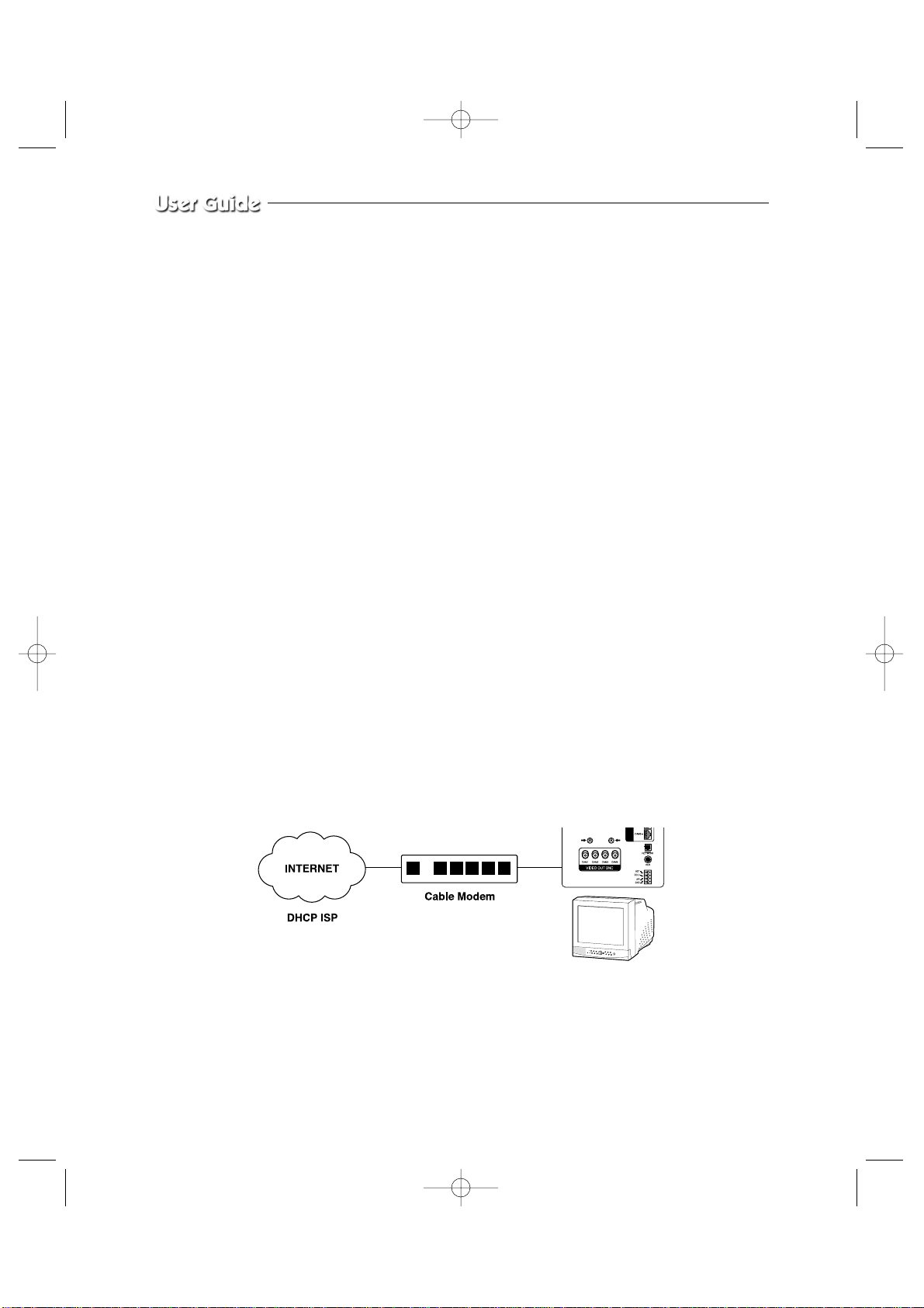
1) Connect as the figure below and turn on the power of each equipment in the
following order.
Eng-32
SSC21WEB-2 2004.8.25 6:30 PM Page 32
Page 33
Eng-33
2) Move to ‘DHCP...’ by using œœENTER
√√
at NETWORK ACCESS, then press ENTER
SWITCH to set to DHCP.
3) DNS 1 and DNS 2 will be automatically set to DNS as shown below.
Use œœENTER
√√
switch to change it.
4) After setting, move to the main screen by using the MENU BOTTOM.
5) Set values will be stored as shown below. It takes 2 or 4 seconds.
On completion of setting to DHCP setup, the screen, [D] is displayed.
If the network connection is cancelled or cut, [D] starts blinking.
6) You can view the video source of the SSC21WEB from a remote location PC.
7) Make sure the remote PC meets the minimum specification requirements described in
chapters 1 and 2, and make sure that the PC is internet capable and set up to be able to
browse the internet.
06/01/03 13:14:00
DHCP ACCESS
DNS 1 168.126.63.001
DNS 2 168.126.63.002
06/01/03 13:14:00
NETWORK SETTING
[D] 13:14:00
CAM1
SSC21WEB-2 2004.8.25 6:30 PM Page 33
Page 34
Eng-34
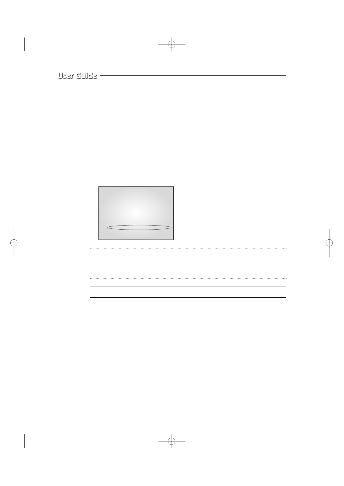
8) Open your Internet Explorer web browser, type in the following in the URL window and
press Enter.
http://sff0000.websamsung.net
Where ff0000 is the MAC address of your SSC21WEB in this example.
If your SSC21WEB’s MAC address is ff0001, then type in ff0001 instead of ff0000
* Note :
MAC Address.
Locate the MAC Address of the SSC21WEB (each SSC21WEB has its own
unique MAC address)
It can be checked in ‘7.NETWORK SETUP” of SETUP MENU’.
It is the last 6 digits as shown below.
CAUTION
If you change the HTTP port number 80 to 82 then must type like below in address bar.
http://sff0000.websamsung.net:82
06/01/03 13:14:00
NETWORK ACCESS OFF
NETWORK STATUS
IP ADDR 192.168.1.200
GATEWAY 192.168.1.65
SUBNETMASK 255.255.255.0
DNS 1 168.126.63.001
DNS 2 168.126.63.002
MAC ADDR 00:30:6f:ff:00:00
CURRENT MODE STATIC
At this time, you should add “s” in front of “mac address”.
SSC21WEB-2 2004.8.25 6:30 PM Page 34
Page 35
Eng-35
ADSL User (PPPoE)
- Constituted by IP on PPPoE (ADSL)
SSC21WEB products can be used on the network using IP through PPPoE (ADSL).
In case of a user (EX : ADSL user) who needs ID and password of the communications that he subscribes for in case of internet connection, the configurations using
PPPoE would be available.
In case of a configuration using PPPoE, SSC21WEB connection is made through
the domain names (EX : http://sff0000.websamsung.net) that are automatically registered in our DDNS server, you do not need to enter IP address, Subnet Mask and
Gateway in the network tab of Admin Mode.
The proper domain manes of SSC21WEB are automatically registered to DDNS
server installed in our company in case of ADSL modem connection.
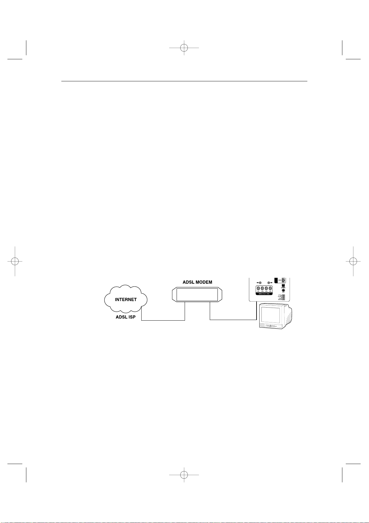
1) Connect as the figure below and turn on the power of each equipment in the following
order.
2) MOVE TO EACH item by using œœENTER
√√
switch, and change the set value.
3) Move to ‘PPPoE...’ by using at NETWORK ACCESS.
Press ENTER SWITCH to set to PPPoE.
SSC21WEB-2 2004.8.25 6:30 PM Page 35
Page 36
Eng-36
4) When the PPPoE (ADSL) type in the User Name and Password (and Confirm Password)
given to you by the ADSL Service Provider.
CAUTION
In case of using ADSL (ISP-internet service provider, you must type correct User Name
and Password by ISP to connect to SSC21WEB. If you type incorrect User Name or
Password, you can not see the image transferred from SSC21WEB.
5) USER ID and PWS can be 40 digits maximum. Only the Arabic numerals,@ and small
characters can be used.
Please that capital letters are not supported when you get USER ID AND PWS from
ADSL Service Provider.
6) DNS 1 and DNS 2 will be automatically set to DNS as shown below.
7) Use œœENTER
√√
switch to change it.
8) After setting, move to the main screen by using the MENU BOTTOM.
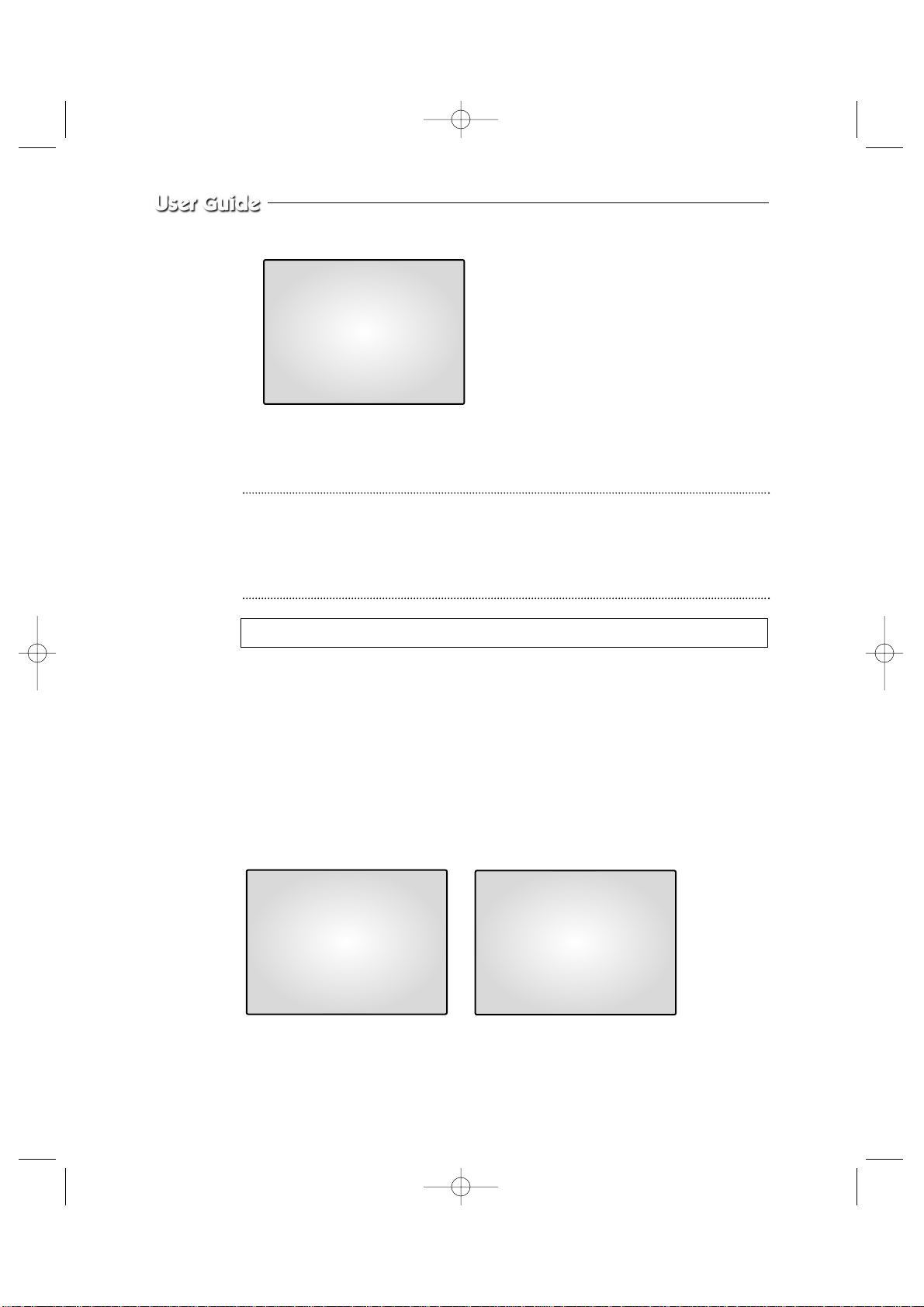
9) Set values will be stored as shown below. It takes 2 or 3 seconds.
On completion of setting to PPPoE(ADSL)setup, the screen, [P] is displayed.
If the network connection is cancelled or cut, [P] starts blinking.
06/01/03 13:14:00
PPPoE
...
ACCESS
DNS 1 168.126.63.001
DNS 2 168.126.63.002
USER ID
********
USER PWD
********
06/01/03 13:14:00
NETWORK SETTING
IP and PASSWORD can be inputted to 40 characters in the maximum.
[P] 13:14:00
CAM1
SSC21WEB-2 2004.8.25 6:30 PM Page 36
Page 37

Eng-37
10) You can view the video source of the SSC21WEB from a remote location PC.
11) Make sure the remote PC meets the minimum specification requirements described in
chapters 1 and 2, and make sure that the PC is internet capable and set up to able to
browse the internet.
12) Open your Internet Explorer web browser, type in the following in the URL window and
press ENTER.
http://sff0000.websamsung.net (Indicate all by URL picture)
Where ff0000 is the MAC address of your SSC21WEB in this example.
If your SSC21WEB’s MAC address is ff0001, then type in ff0001 instead of ff0000.
* Note : MAC Address.
Locate the MAC Address of the SSC21WEB (each SSC21WEB has its own
unique MAC address)
It can be checked in ‘7.NETWORK SETUP” of SETUP MENU’.
It is the last 6 digits as shown below.
CAUTION
If you change the HTTP port number 80 to 82 then must type like below in address bar.
http://sff0000.websamsung.net:82
CAUTION
In cases where DNS server address of PC is not set and the connection using domain
name is not available, Please consult with the network administrator and be sure to set
DNS server address.
06/01/03 13:14:00
NETWORK ACCESS
NETWORK STATUS
IP ADDR 192.168.1.200
GATEWAY 192.168.1.65
SUBNETMASK 255.255.255.0
DNS 1 168.126.63.001
DNS 2 168.126.63.002
MAC ADDR 00:30:6f:ff00:00
At this time, you should add “s” in front of “mac address”.
SSC21WEB-2 2004.8.25 6:30 PM Page 37
Page 38
Eng-38
CAUTION
The connection to SSC21WEB is unavailable for about 2~5 minutes after ADSL
Modem’s power ON.
Since the connection would not be available, as IP is not received from ADSL communications, please reboot by turning off the power of ADSL Modem and SSC21WEB for
more than 5 seconds and then try to connect again.
3-8) SSC21WEB basic setting
1) Open your Internet Explorer web browser, type in the following in the URL window and
press ENTER. -Refer 3-7) Network Installation
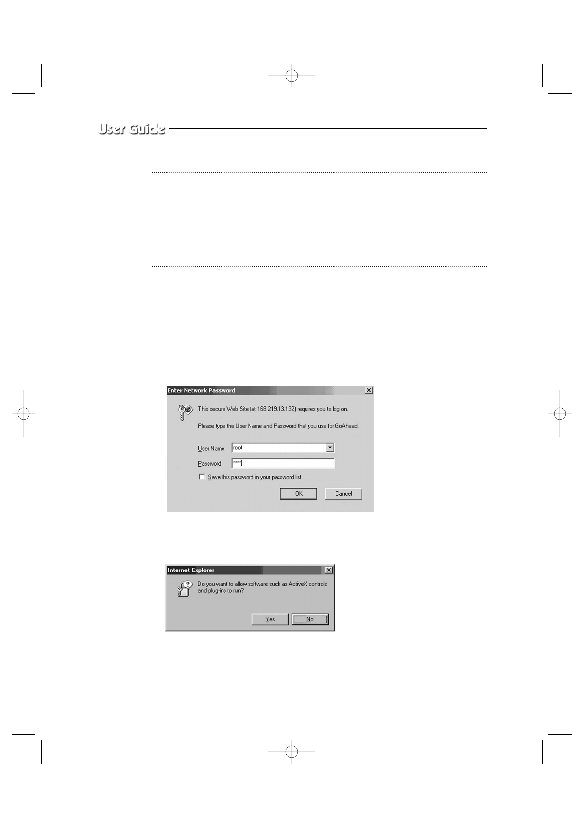
2) When you choose the Admin menu, it asks you the Admin ID and password.
3) Type in root / root. On delivery, they are “root” (administrator’s ID) / “root” (administra-
tor’s Password). The password can be changed on Admin Menu.
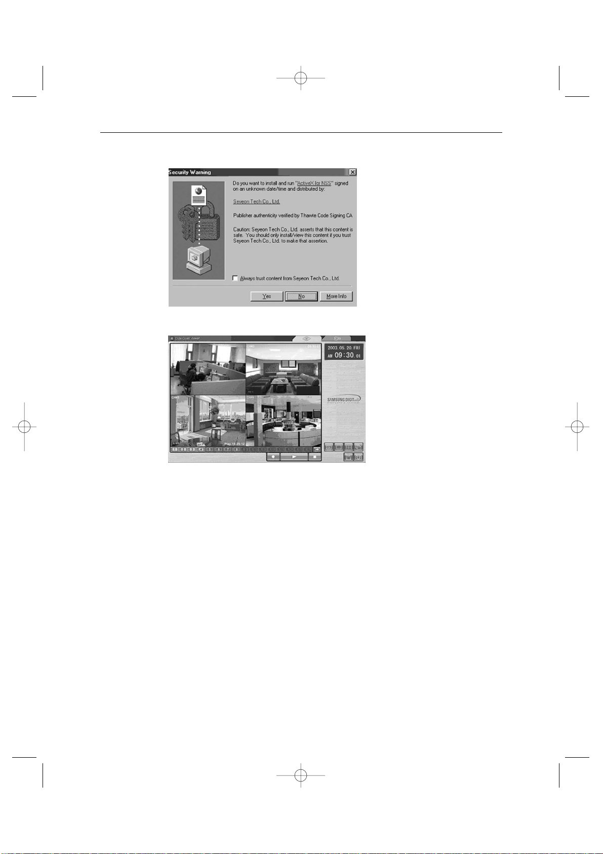
4) If this is the first time you run this procedure on this PC, then you will see the following
“Active X controls and plug-ins to run” screen.
5) Click “YES”. This will automatically download the necessary Active X Controls to oper-
ate the Remote Viewer.
It takes about 20 seconds at the first connection.
SSC21WEB-2 2004.8.25 6:30 PM Page 38
Page 39
Eng-39
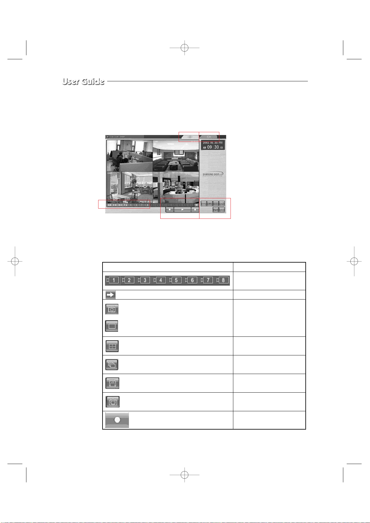
6) When you enter properly, a window appears as shown below.
SSC21WEB-2 2004.8.25 6:30 PM Page 39
Page 40
Eng-40
3-8-1) “LIVE” MENU
- CAMERA SELECT
Initial display mode of monitor if QUAD A.
- Remote Viewer Function Buttons
KEY Type Function
Choose a camera by channel
Ch 1 ~ Ch 8
CHANNEL NEXT
SINGLE MODE
(1ch Default selected)
320 X 240 Size
720 X 480
QUAD MODE
(QUAD Default selected)
SEQUENCE MODE
SAVE
CAPTURE
REC
SSC21WEB-2 2004.8.25 6:30 PM Page 40
Page 41
Eng-41
PLAY
STOP
LIVE MODE change
ADMIN MODE change
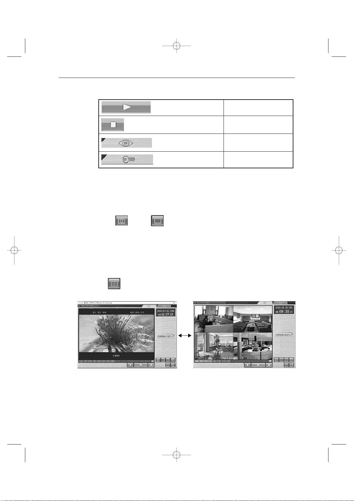
- SINGLE SCREEN DISPLAY
In case users want to see the camera image at full mode,
Select a target camera by turning camera select key.
After that it’ selected camera image will be displayed at full screen.
* AT SINGLE DISPLAY
- QUAD MODE DISPLAY
User can switch SINGLE DISPLAY and SEQUENTIAL DISPLAY MODE or QUAD
DISPLAY MODE or QUAD A (QUAD B) TO QUAD B (QUAD A) Press the
Sequence KEY
• AT QUAD MODE DISPLAY
QUAD A: QUAD DISPLAY MODE From Camera1 to Camera4
QUAD B : QUAD DISPLAY MODE From Camera5 to Camera8
Original Size Large Size
SSC21WEB-2 2004.8.25 6:30 PM Page 41
Page 42
Eng-42
- Auto SEQUENCY DISPLAY MODE
Pressing on the SEQUENCE KEY on the front allow to automatically switch to SINGLE MODE Full screen or QUAD MODE.
If the DWELL TIME SETTING of SETUP MENU is set to 3 seconds and the
SEUQENCY KEY is pressed at this time, the operation will be carried out as follows.
(NO signal channel will be skipped while single screen is auto-switching)
* SINGLE MODE SEQUENCE DISPLAY
->
Press SQUENCE KEY When SINGLE MODE (camera select key) is
displayed at full screen.
* QUAD MODE SEQUENCE DISPLAY
->
Press SQUENCE KEY When QUAD A (QUAD B) MODE is displayed.
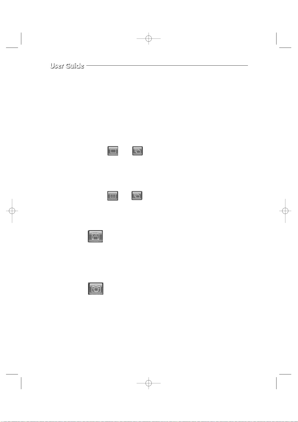
- SAVE MODE
Pressing on the SAVE KEY on the front, you can change the name of the
DIRECTORY
.
- CAPTURE MODE
Pressing on the CAPTURE KEY on the front, you can store each picture in the form of
M-JPEG.
- Motion Picture Recording and Playback
SSC21WEB-2 2004.8.25 6:30 PM Page 42
Page 43
Eng-43
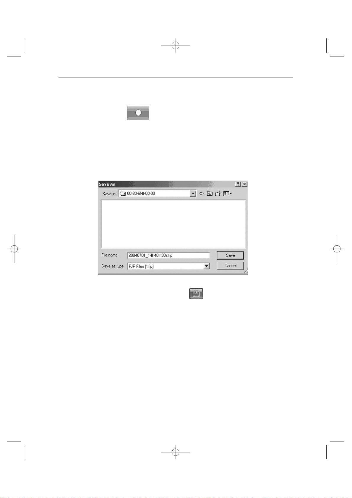
1. Recording
When you make a recording from the Viewer, the file is automatically saved onto a
directory preset by the Viewer by default.
This directory is usually “C:\Program Files\Samsung \SSC21WEB\00-30-6F-FF-00”
00-30-6F-FF-00 is the MAC ADDRESS of the product.
(user can change this in the SAVE KEY .Record Folder setting),
where “Server Name” is the name of your SSC21WEB you have given during setup of
the SSC21WEB.
If you have connected to and recorded from more than one SSC21WEB on the same PC,
there will be more than one “Server Name” directory.
You can always locate the file by choosing the Server Name directory.
Within the Server Name directory, files are automatically saved with filenames in time
stamped format.
SSC21WEB-2 2004.8.25 6:30 PM Page 43
Page 44
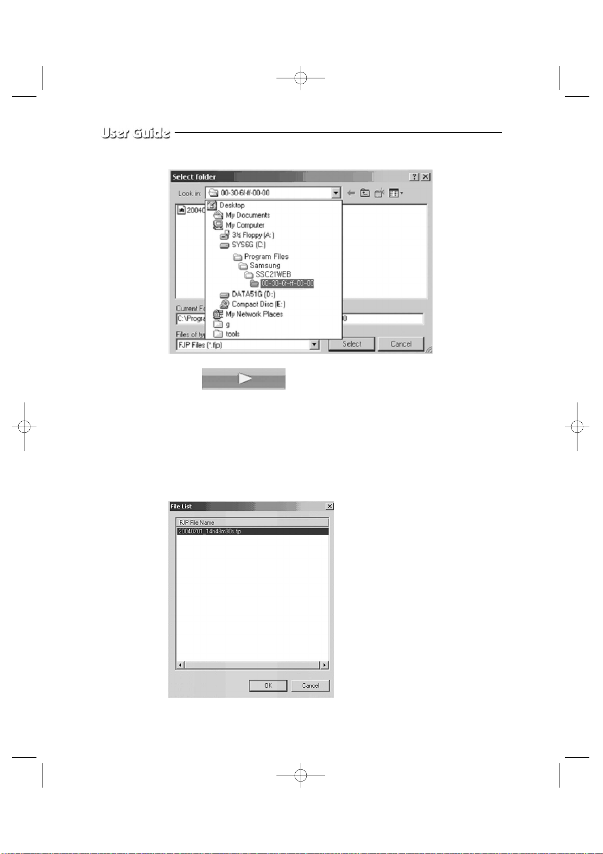
2. PLAY
When you select on a play key and press the Open button or double click the file, that
file will play back on the Remote Viewer as a motion clip. When the file has finished
playing or when you press the Stop button, the Remote Viewer will go back to Live
screen. You can select several files simultaneously at once (up to 10)
and the files will be played back in the order of the file name (by date and time).
Eng-44
SSC21WEB-2 2004.8.25 6:31 PM Page 44
Page 45
Eng-45
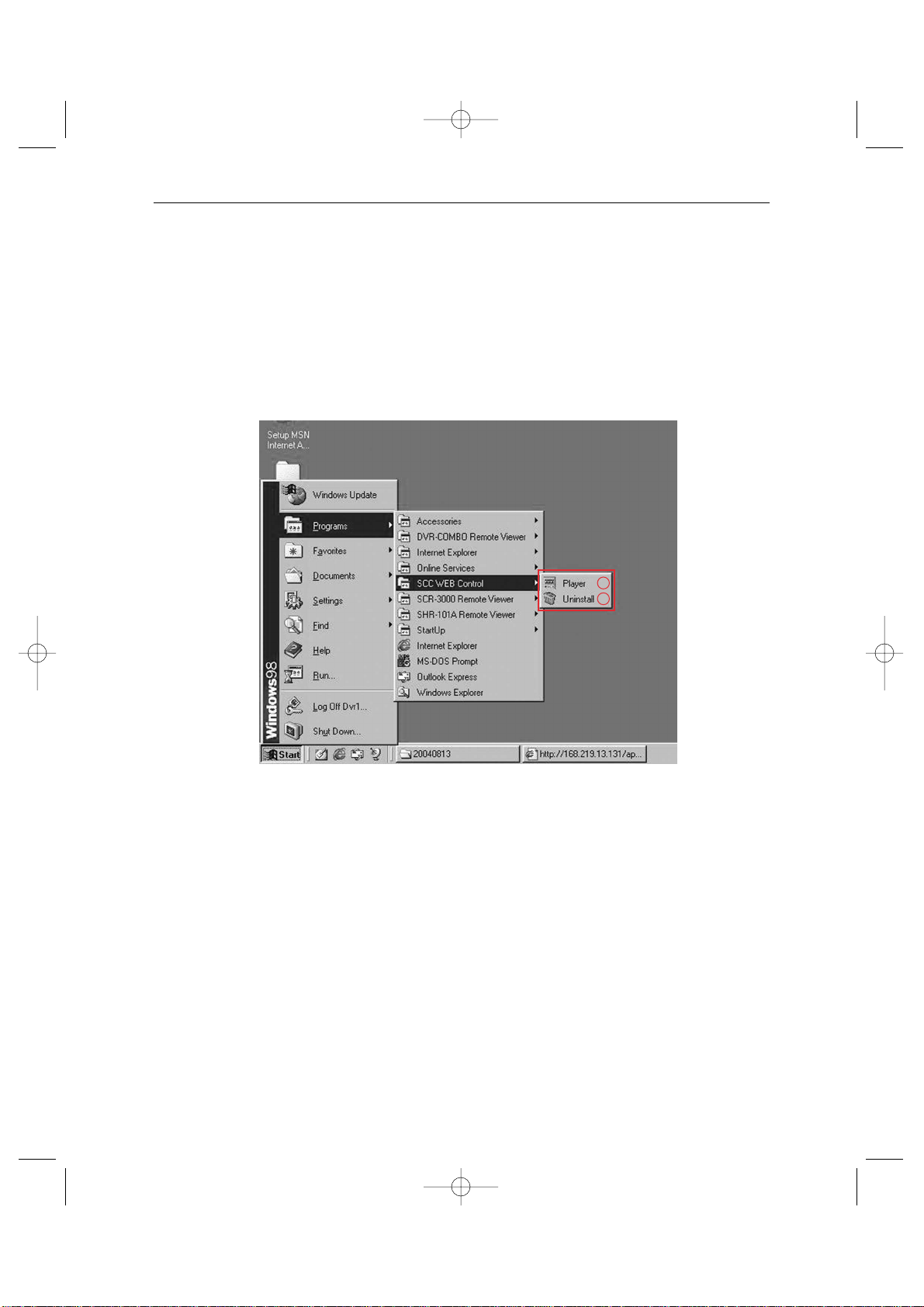
3. PLAYER
- Player installation/execution/deletion
- Installation
Player will be installed together when it is connected to SSC21WEB.
- Execution (Follow the instruction to execute it separately.)
Click Start Program —> SSC WEB Control —> Player. (Fig. 3-!)
FIG.3
- Deletion
Click Start —> Program —> SSC WEB Control —> Uninstall. (Fig. 3-@)
1
2
SSC21WEB-2 2004.8.25 6:31 PM Page 45
Page 46
Eng-46
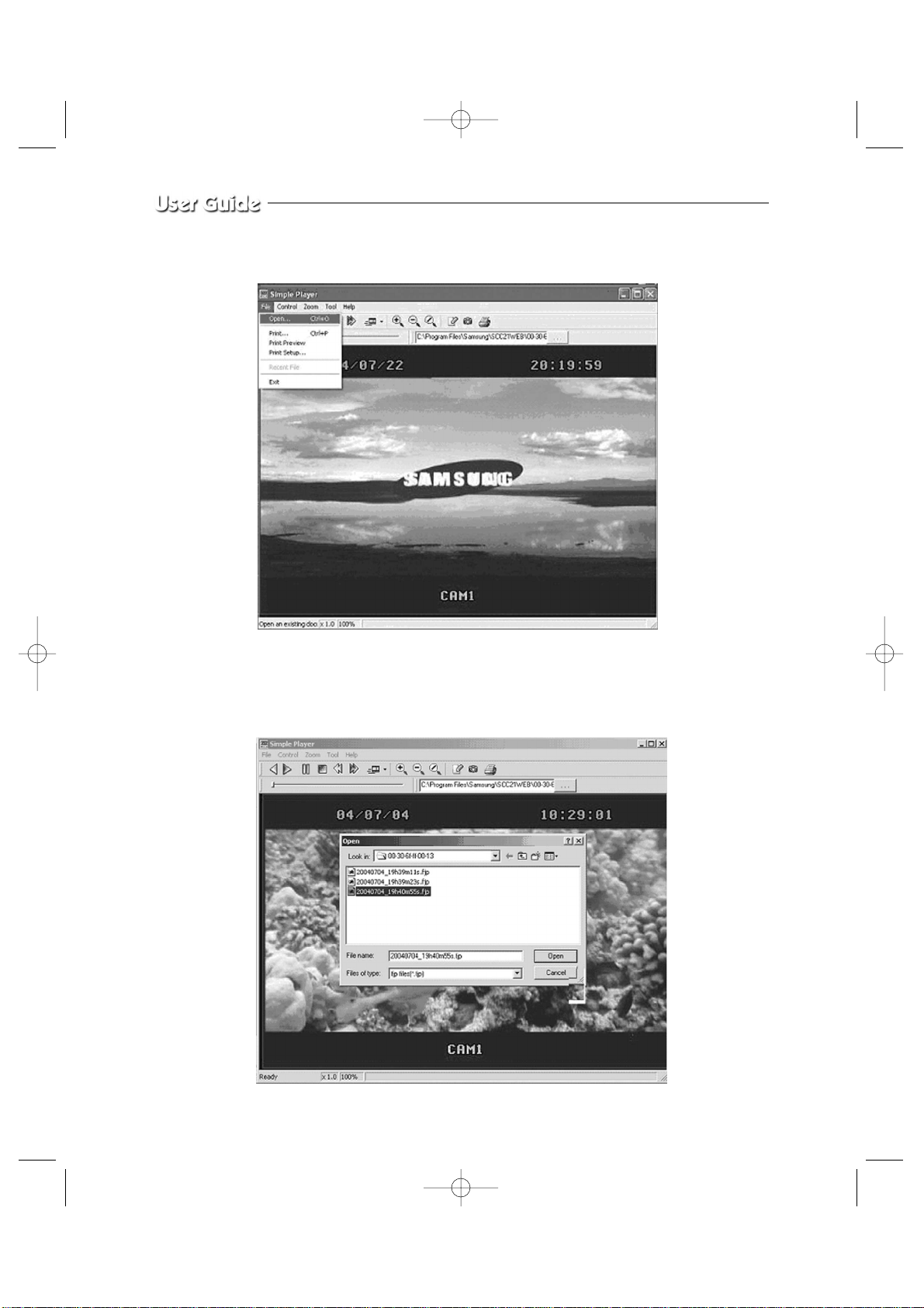
- Program screen configuration
- How to play
1. Play - back
File - Open... Selecting this, you can choose one between fjp and jpg on a window
as shown below.
SSC21WEB-2 2004.8.25 6:31 PM Page 46
Page 47
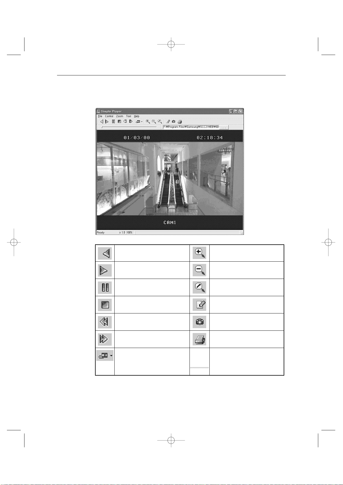
Eng-47
Having chosen and opened a file, you will see a picture as shown below.
Reverse playback Enlarge
Playback Reduce
Pause Original size
Stop Partial storing(AVI support)
To the back frame Save the present frame as a
JPEG image
To the front frame Print
Speed control Display the playback speed,
magnification, and information
on the storage.
Status
bar
SSC21WEB-2 2004.8.25 6:31 PM Page 47
Page 48
Additional function (Tool)
- Partial recording
- Snap shot
- Print
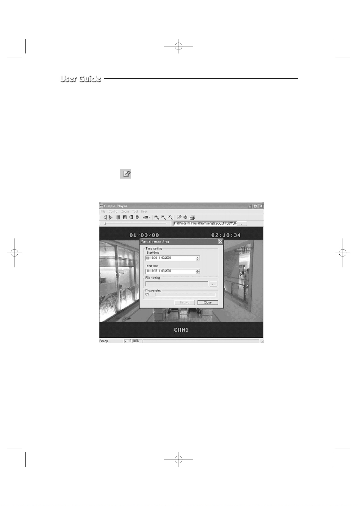
- Partial Recording
Partial recording is to separate a section from the file selected and played and save it as
a form of AVI.
Select in the toolbar and a window will appear as shown below. Start time and
End time of the file will be displayed and the user can decide the section.
You need to type in the correct time to execute the partial recording function.
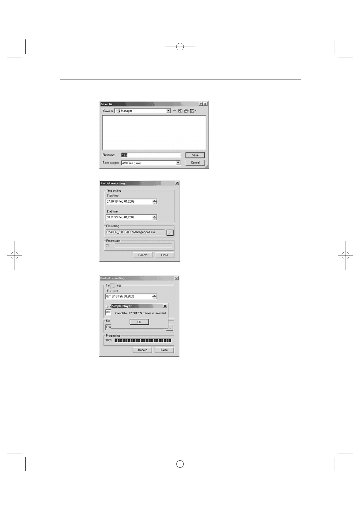
Go to File setting and type in the file name you want to make. Awindow will appear as
shown below.
Eng-48
SSC21WEB-2 2004.8.25 6:31 PM Page 48
Page 49
Eng-49
And press ‘Save’.
Then press ‘Record’ button and the picture below shows that it was completed.
* Note :
“AVI file frame speed setting” Frame control function of Dialogue box is to con-
trol the number of frames of AVI files. Although the original file has been recorded
at a speed of 10 frames per second, 30 frames or 3-second frames of the original
file will be stored and become a “second in an AVI file if you set the number of
AVI file frames to 30 frames. In this case, the AVI file will be played more rapidly
than the speed of the original when it is played on a media player. Please regulate
the “AVI file frame speed setting” properly depending on the speed of the original.
SSC21WEB-2 2004.8.25 6:31 PM Page 49
Page 50
- Snap shot
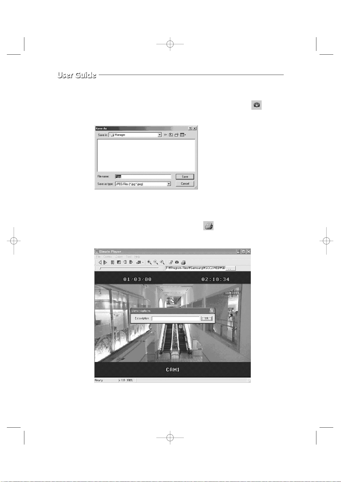
It is a function to save the present image as a form of a jpeg file. Select in the
toolbar. The result will be as follows.
Type in the file name and press ‘Save’to store it as a jpeg file.
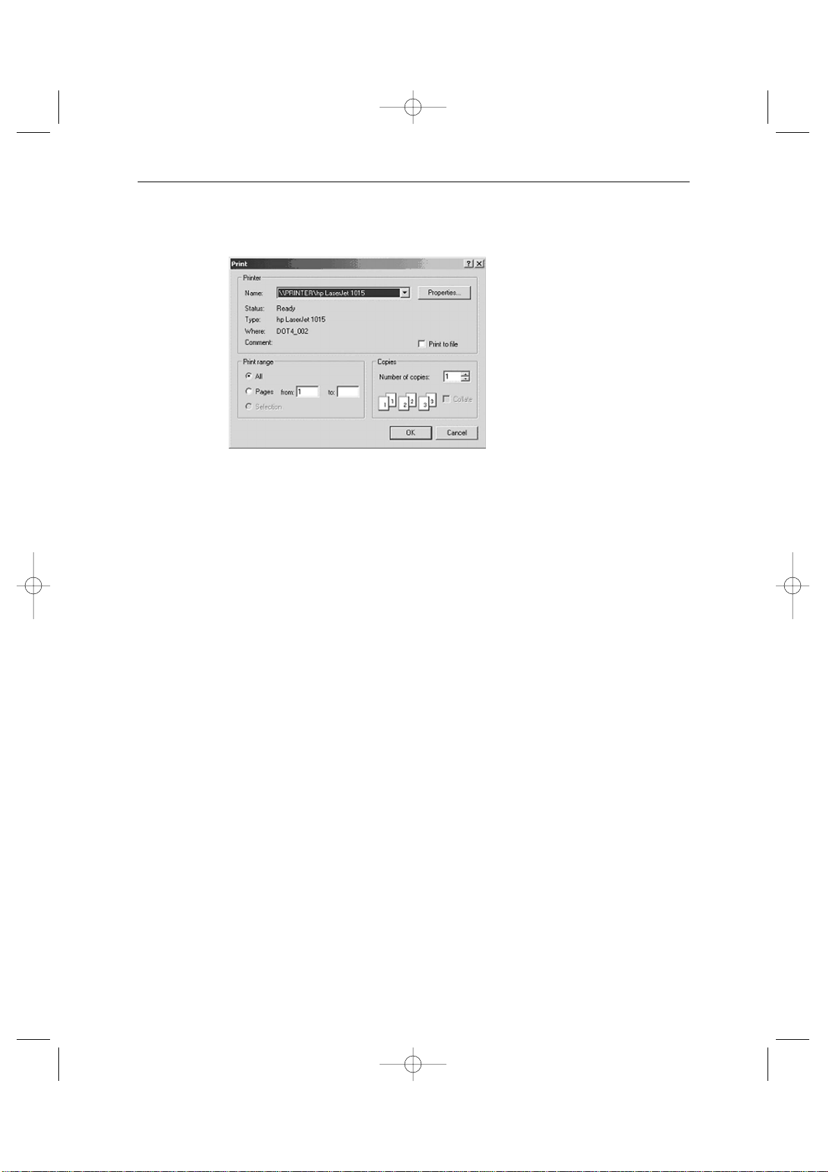
It is a function to print the present image. Select in the toolbar. The result will
be as follows.
Eng-50
SSC21WEB-2 2004.8.25 6:31 PM Page 50
Page 51
Eng-51
Type in the phrase you added in ‘Description’. Then press the ‘OK’ button.
Select Print and press ‘OK’.
SSC21WEB-2 2004.8.25 6:31 PM Page 51
Page 52
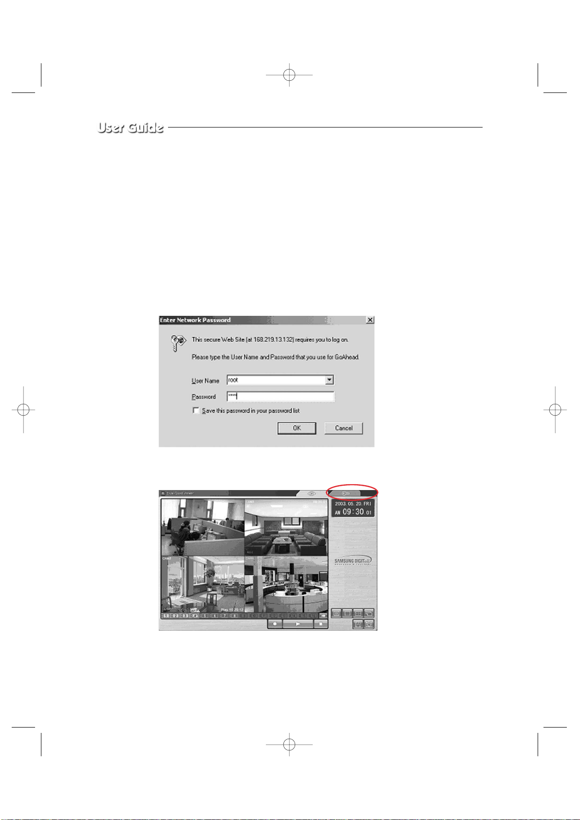
Admin Menu
It is an administrator’s menu to set the general items on SSC21WEB Server. To use this
menu, you need the administrator’s ID and Password.
On delivery, they are “root” (administrator’s ID) / “root” (administrator’s Password). The
password can be changed on Admin Menu.
Admin Menu Entering
1) Click the Admin menu and a login window will appear.
2) When you connect to the SSC21WEB Server through Web browser, the initial screen will
be as follows.
Eng-52
SSC21WEB-2 2004.8.25 6:31 PM Page 52
Page 53
Eng-53
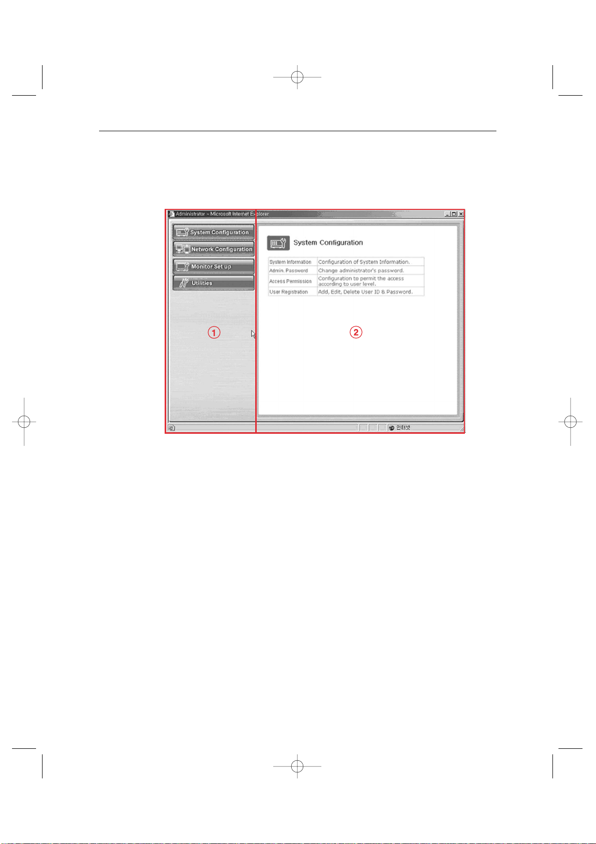
3) Type in the administrator and password in the user’s name and password columns and
press Enter key to execute the Admin Menu as shown below.
4) Screen configuration
! : General menus of Admin Menu. The menus related to SSC21WEB Server are
divided into System, Network, Monitor Setup, and Utilities in the main. Each of
them has several sub menus.
@ : When you click one of the main menus (System Configuration, Network
Configuration, Monitor Setup, Utilities), its sub menus and simplified explanation
on them will appear.
SSC21WEB-2 2004.8.25 6:31 PM Page 53
Page 54

• Admin Menu Structure
Eng-54
Category Main Menu
System Configuration System Information
Admin. Password
Access Limitation
User Registration
Video
Alarm Notification
Network Configuration Network Configuration
PPPoE (ADSL)
Network Ports
View Network Status
Network Status Notification
DDNS Configuration
Monitor Setup Date & Time
View Event Log
Display
Dwell Time
Title
Alarm
Utilities Save Configuration
Reboot
System Update
SSC21WEB-2 2004.8.25 6:31 PM Page 54
Page 55
Eng-55
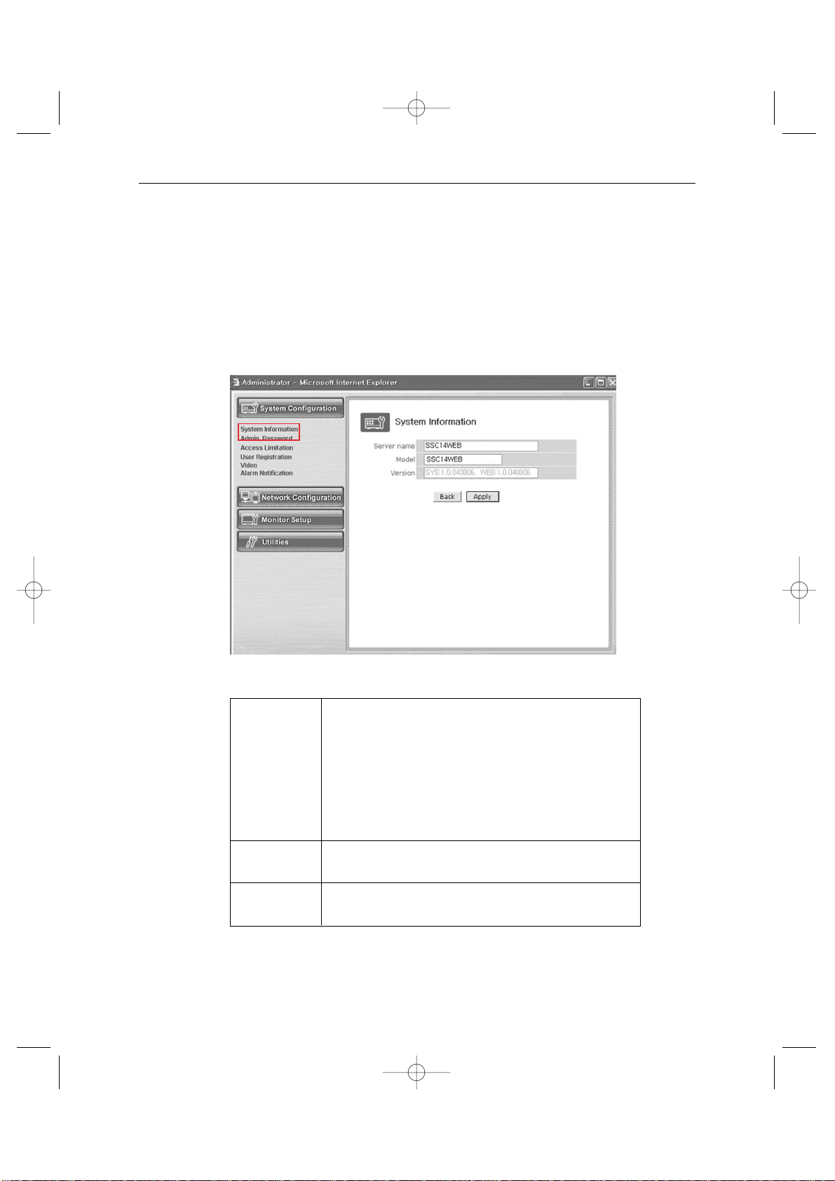
3-8-2) System Configuration Menu.
1. System Information
In this menu, you can check the information on the system including the name of the
SSC21WEB Server, its model name and the version of the model and change the name of
the SSC21WEB Server.
- Menu Configuration
After completing setting, click Apply button.
If you click the back button, initial values are typed in all fields.
Server Name Type in the name of the SSC21WEB Server.
* Server’s name should be composed of 19 or less numerals
or English alphabets.
It cannot start with a numeral and should start with an
English alphabet.
White characters including a space, tab, and a special letter
cannot be used.
Model SSC21WEB Server product model name SSC21WEB
* This part is only for reading, cannot be changed.
Version SSC21WEB Server product’s version
* This part is only for reading, cannot be changed.
SSC21WEB-2 2004.8.25 6:31 PM Page 55
Page 56
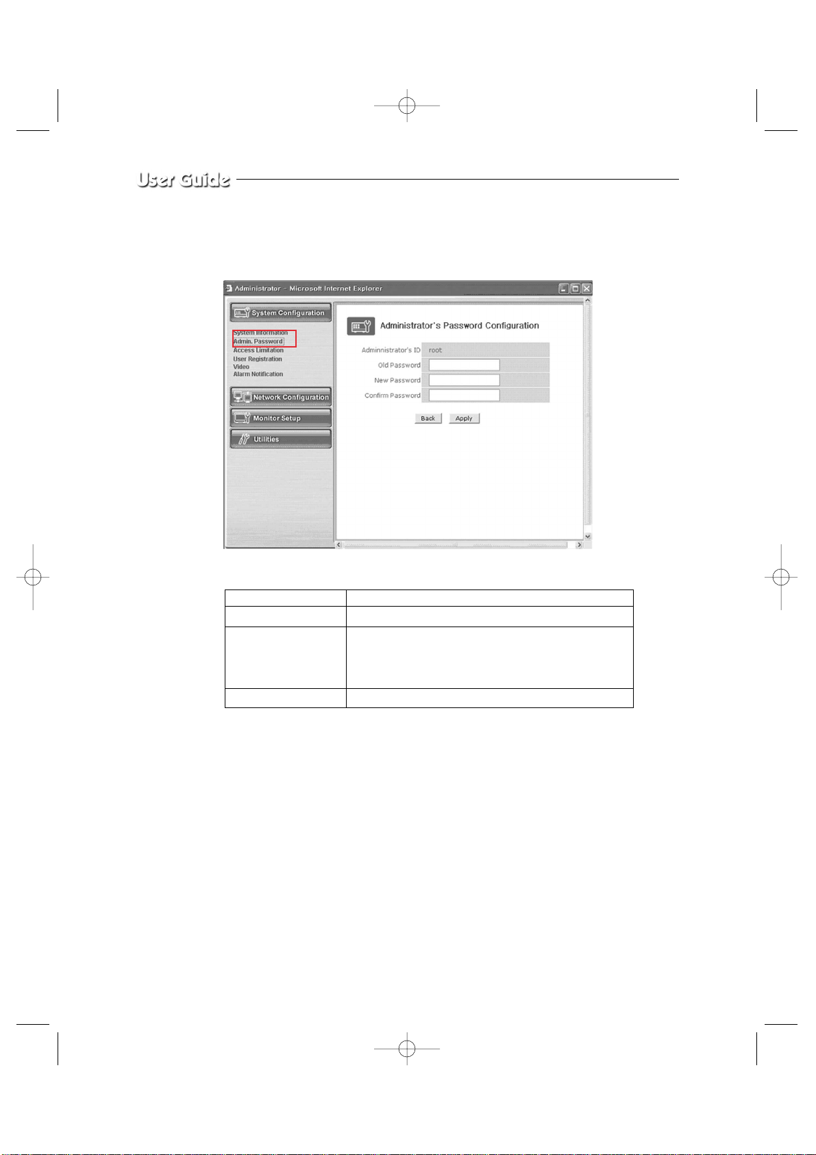
2. Admin Password
In this menu, the password of the administrator (root) can be changed.
- Menu Configuration
After completing setting, click Apply button.
If you click the back button, initial values are typed in all fields..
After clicking the apply button, the new password will be applied.
Then the connection of SSC21WEB Server, which was connected by using the existing
password, to the Web Page will be cut off because the new password is now applied.
The user needs to log in again by using the new password.
Administrator’s ID Administrator’s ID is always “root”.
Old Password The initial password is “root”.
New Password Type the password you want to change into.
* The password should be composed of 4-8 digit
numerals or alphabets.
Confirm Password Type again the password you want to change into.
Eng-56
SSC21WEB-2 2004.8.25 6:32 PM Page 56
Page 57
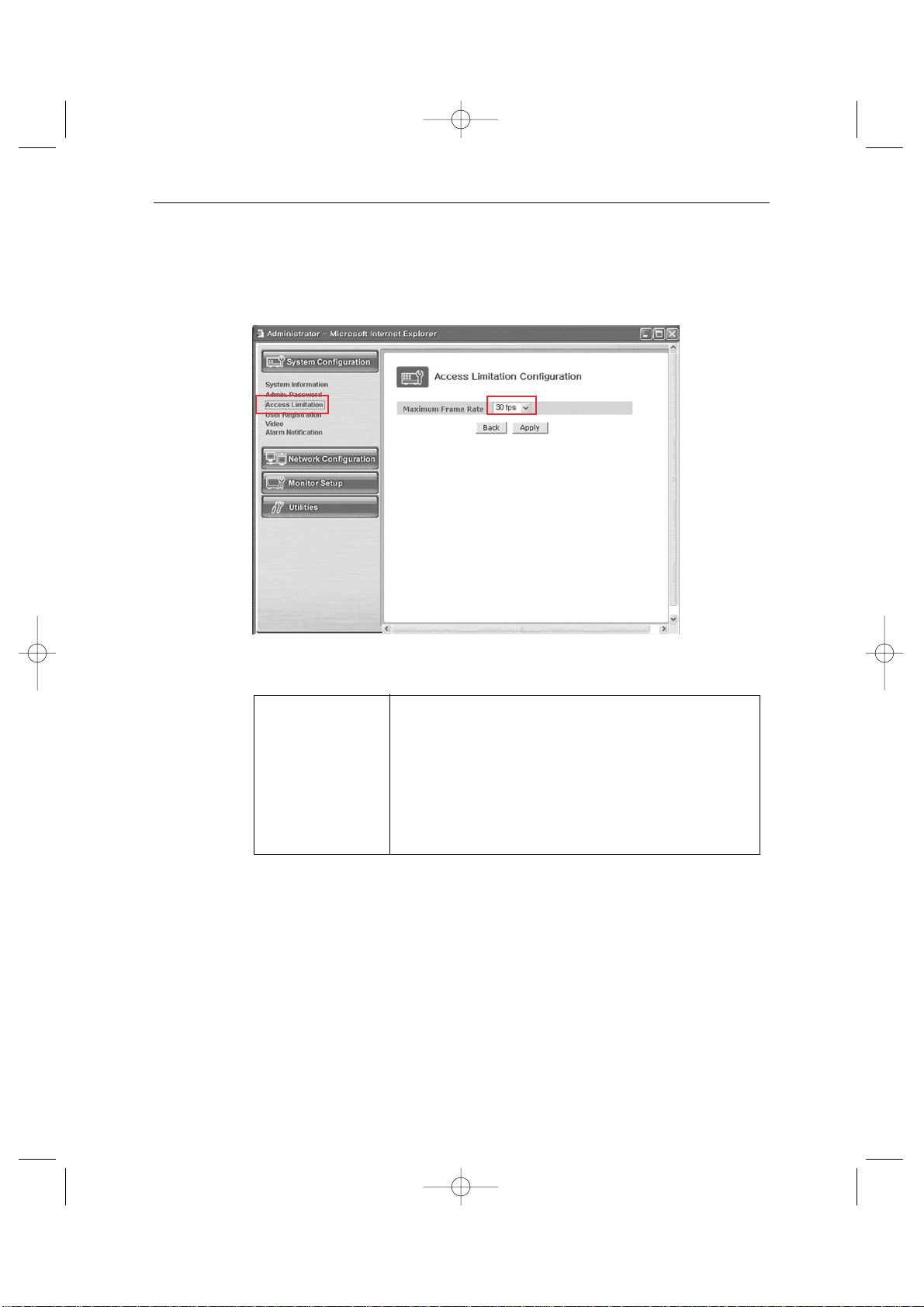
Eng-57
3. Access Configuration
This menu is to set the targets the SSC21WEB Server can have an access to.
- Menu Configuration
After completing setting, click Apply button.
If you click the back button, initial values are typed in all fields.
Access Limitation This is to limit the maximum frame speed when the
Configuration users, who are registered in the system, join and see the
images.
The users, who join in the system after this setting, will be connected at the limited speed.
The access speed can be limited on the Local Network depending on the forwarding state of the network. (30/15/10/5/2/1 ips)
SSC21WEB-2 2004.8.25 6:32 PM Page 57
Page 58
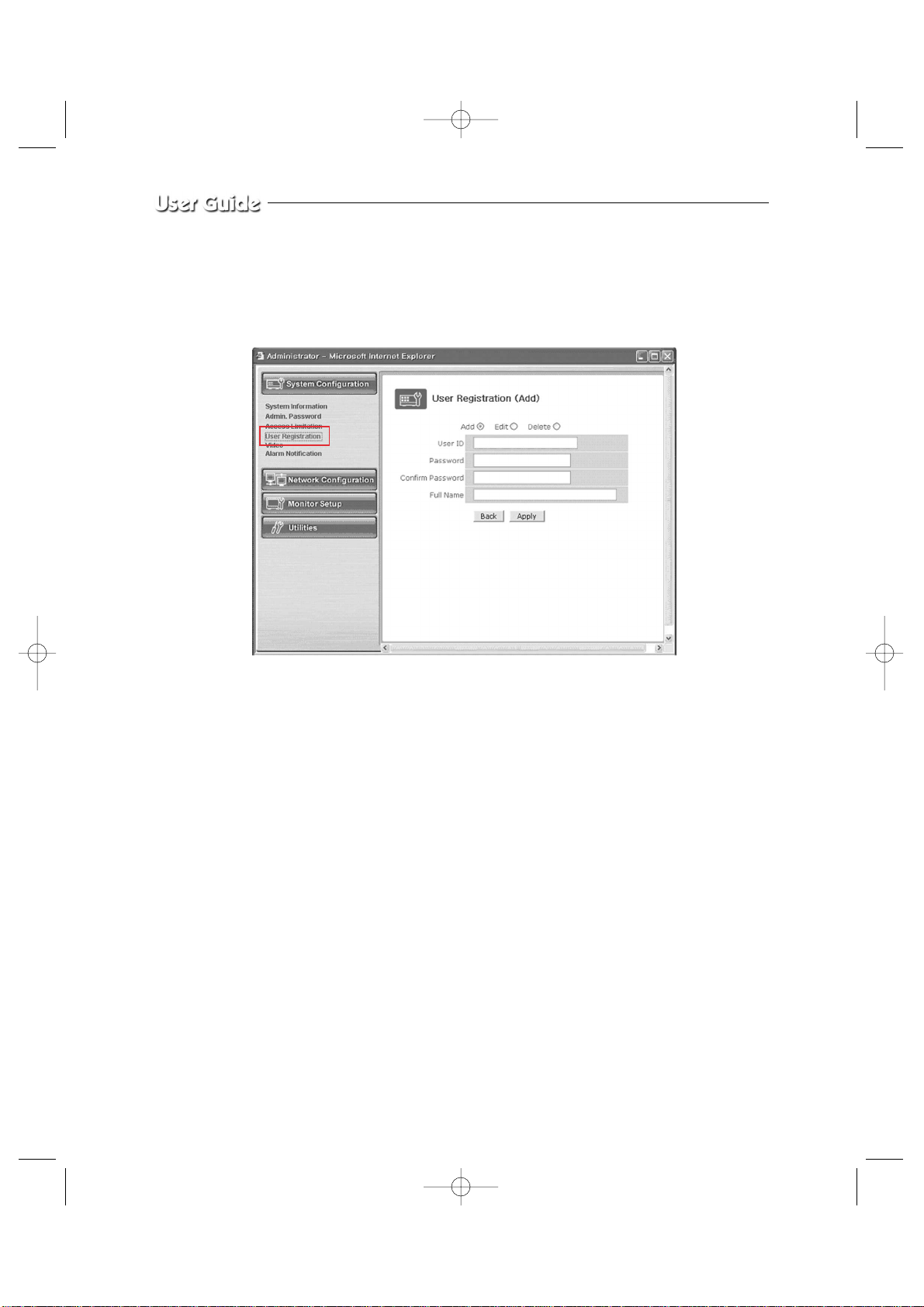
Eng-58
4. User Registration
This is a user control menu to register, change, or delete the users who can use the
SSC21WEB Server.
SSC21WEB-2 2004.8.25 6:32 PM Page 58
Page 59

Eng-59
- Menu Configuration
User ID Decide the ID of the person you want to register.
Password Decide the password of the person you want to register.
Confirm Type again the password of the person you want to register.
Password
Full Name Type in the name of the person you want to register.
Add This is a menu to register a user. It is to fix the user’s ID, Password,
name, and the authority of the user how far he/she can use the system.
- Type in the user’s ID in the User ID column.
- Type in a password in the Password and Confirm
columns. The user’s ID and the password should be composed of 31 or less numerals or letters.
- Type in the name of the user in Full Name column.
Edit On this menu, you can change the existing password, name, and
access right of the user.
The user’s ID cannot be changed. The configuration of the menu is
same as Add, however you should select the user’s ID on this menu.
- Choose Edit menu.
- Click “Select User ID” in User ID and click the user’s
ID you want to edit.
- Modify the password, name, and access right of the user
and click Apply button to apply the modified items.
Delete This menu is to delete the registered user.
- Choose Delete menu.
- Choose the user’s ID you want to delete in the box.
- Click Delete button to delete the ID.
- Click Save button to complete registration.
After completing setting, click Apply button.
If you click the back button, initial values are typed in all fields.
SSC21WEB-2 2004.8.25 6:32 PM Page 59
Page 60
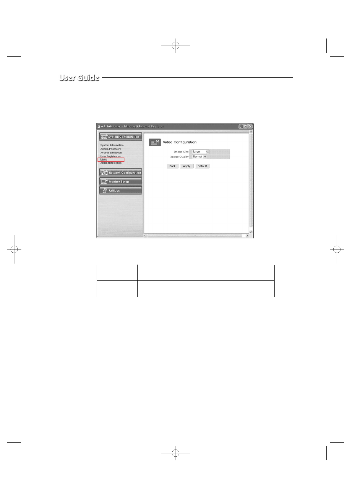
Eng-60
5. Video Configuration
This is to set the data to be added in the video data and set an environment for each channel.
- Menu Configuration
After completing setting, click Apply button.
If you click the default button, initial values are typed in all fields.
Image Size This is to choose the size of the image of video data.
You can choose between 2 kinds of size (Small / large).
Image Quality This is to choose the quality of the image.
You can choose between 3 levels (High, Normal, Low).
SSC21WEB-3 2004.8.25 6:41 PM Page 60
Page 61
Eng-61
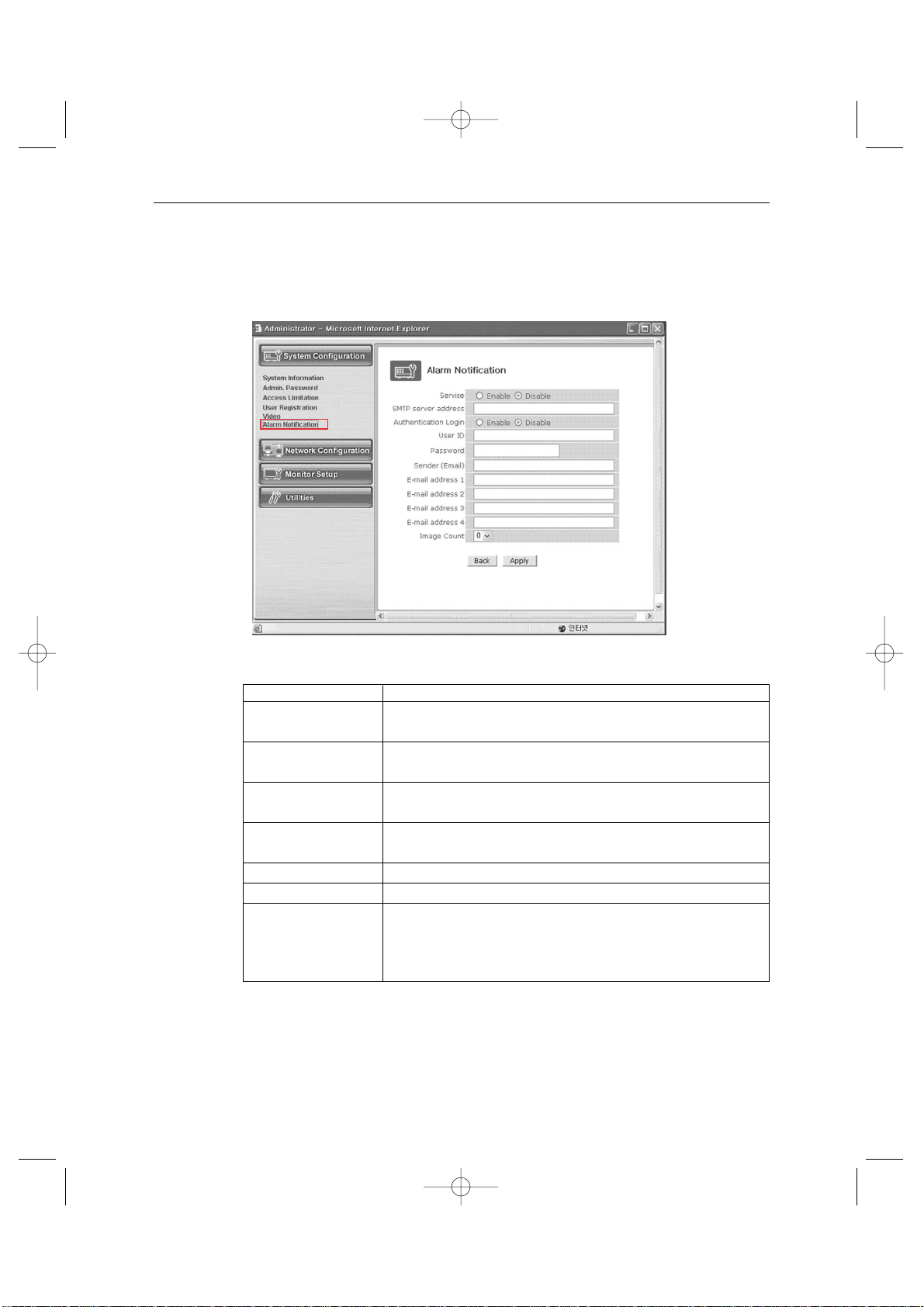
6. Alarm Notification
This notifies the registered users of an alarm arising situation through e-mails.
At this time, maximum 5 M-JPEG pictures, which were stored, can be sent together.
- Menu Configuration
Service Choose if you want to send the ALARM notifying E-MAIL.
SMTP server SMTP server of the ISP that provides SSC21WEB with
address services. ISP’s confirmation required.
Authentication Choose if you want to log in the SMTP of the ISP providing
Login SSC21WEB with services.
User ID ID for the SMTP server of the ISP that provides SSC21WEB
with services.
Password Password for the SMTP server of the ISP that provides
SSC21WEB with services.
Sender (E-mail) Register the E-mail of ADMINISTRATION of SSC21WEB
E-mail address 1 ~4 E-mail addresses you want to send the alarm notification to.
Image count M-JPEG images to send.
Up to 5 pictures can be sent at 0.5-second intervals.
* Some SMTP servers may not support M-JPEG forwarding.
Set this function after checking the SMTP server.
After completing setting, click Apply button.
If you click the back button, initial values are typed in all fields.
On this menu, you can fix the general environment related to the network of the
SSC21WEB Server and check the present status of it.
SSC21WEB-3 2004.8.25 6:41 PM Page 61
Page 62
Eng-62
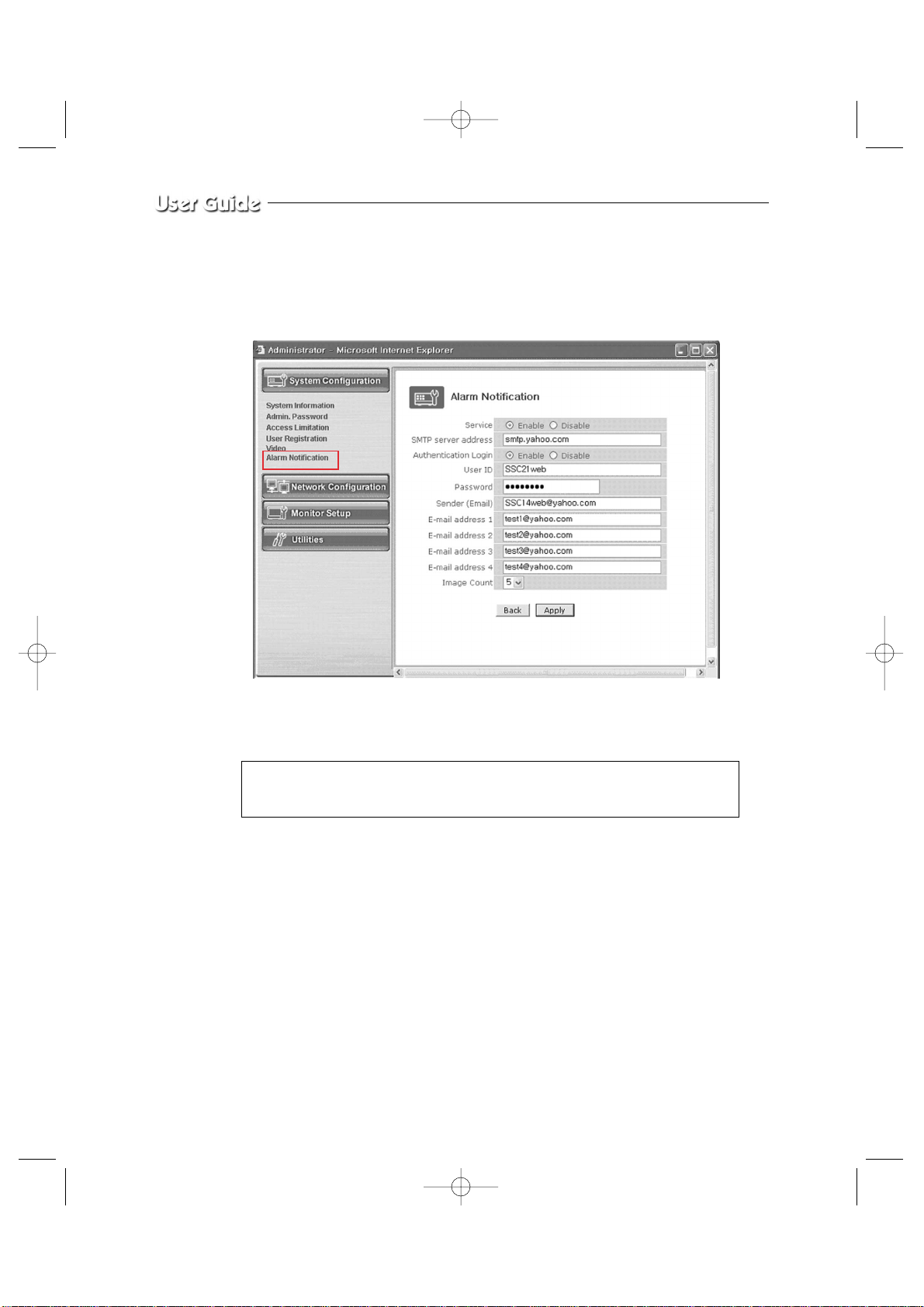
EX) When user who has an e-mail address ([email protected]) and
password(123456) in YAHOO sets “Alarm Notification” in order to send a mail to
[email protected]...
After completing setting, click Apply button.
If you click the back button, initial values are typed in all fields.
In the event of Alarm, please use PLAYER to catch normal JPEG images.
Otherwise, the image size will be reduced to a half JPEG size.
Refer to Eng-46 “How to play” for the detailed usage of PLAYER.
The image transfer is not supported in all SMTP servers. Check the J-PEG
image transfer in your mail account.
SSC21WEB-3 2004.8.25 6:41 PM Page 62
Page 63
Eng-63
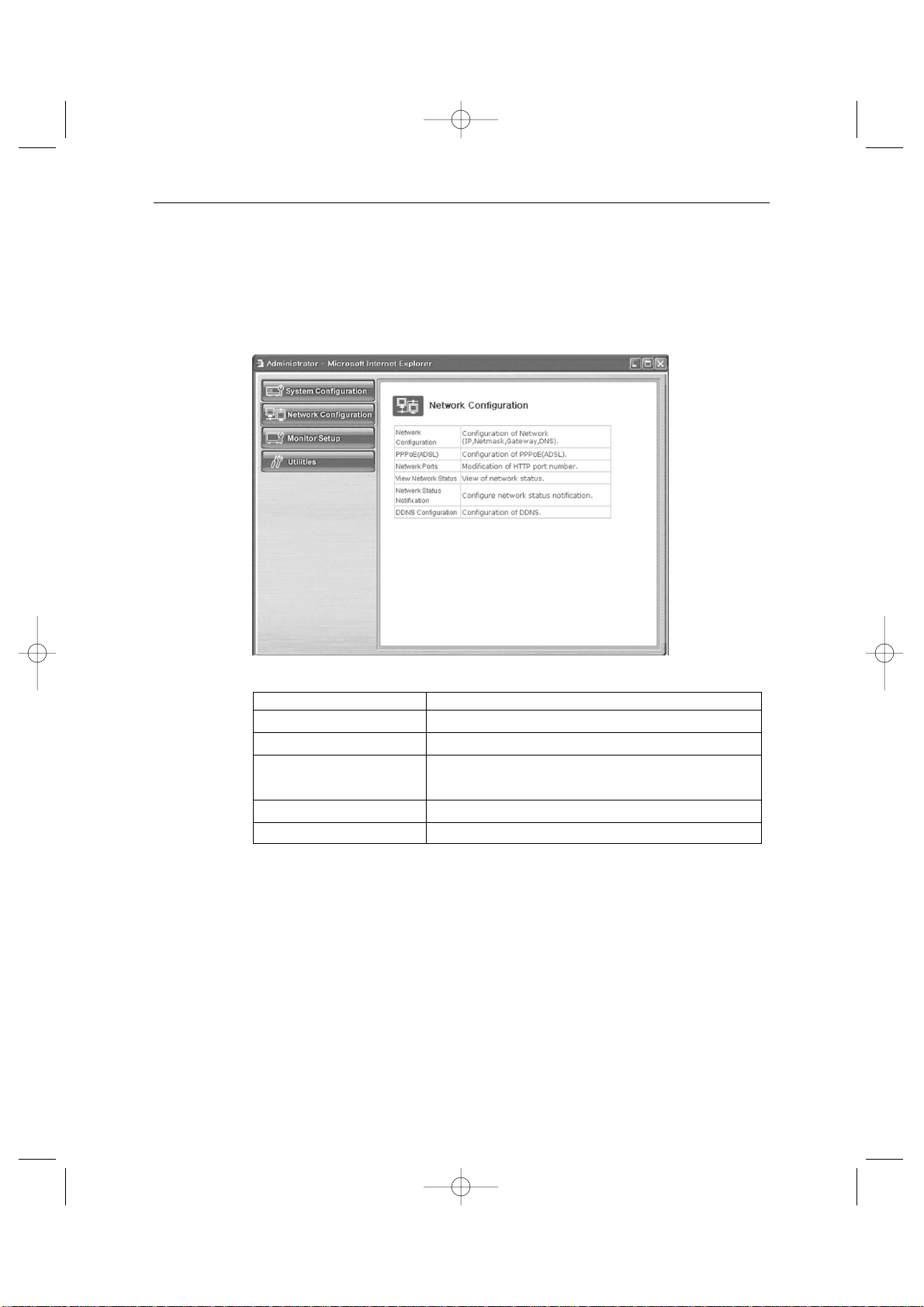
3-8-3) Network Configuration Menu.
1. Network Configuration
On this menu, you can fix the general environment related to the network of the SSC21WEB
Server and check the present status of it.
- Menu Configuration
1) Fix the IP address of the SSC21WEB Server, NetMask, GateWay, DNS1, DNS2, etc.
2) NetMask : This is a column of letters of only 0 or 1 to leave the address of the host
computer alone among the IP Addresses. (Example : “255.255.255.0” is used
for a C-Class serve net capable of maximum 255 host computers. In this line,
“.0” clarify the address of a certain host computer.)
3) GateWay : This is a network point that plays a role as an entrance to other networks.
4) DNS (Domain Name Service) : Aservice to convert a Domain Name (ex.
www.yahoo.com) into an IPaddress (ex. 216.109.127.28).
The SSC21WEB Server uses this service to join the FTP
server or other webs by the Domain Name.
Network Configuration Set “Static IP” or “DHCP”.
PPPoE(ADSL) Set PPPoE (ADSL).
Network Ports Set “Network Port”.
View Network Status Modification of HTTP and other application network
port numbers.
Network Status Notify View of network status.
DDNS Configuration DDNS Configure
SSC21WEB-3 2004.8.25 6:41 PM Page 63
Page 64
Eng-64
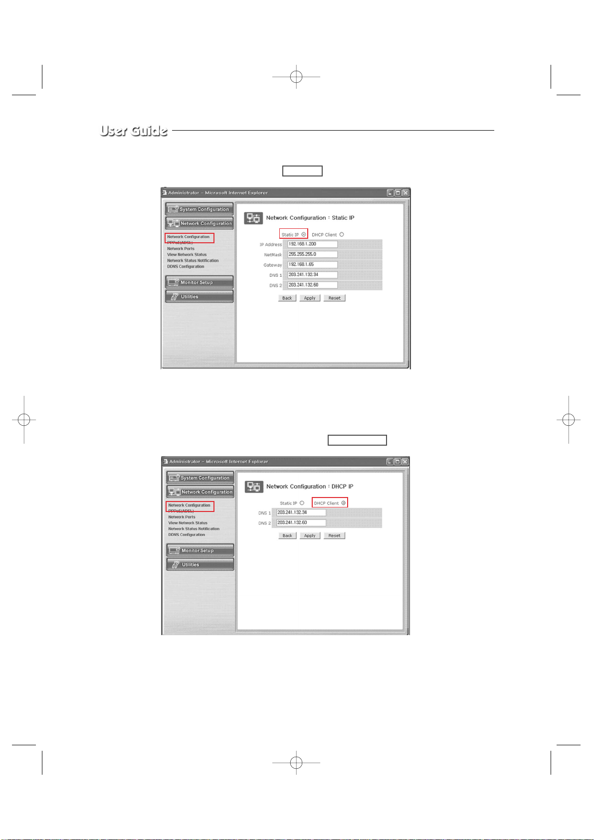
1-1. Network Configuration : Static IP / DHCP Client
1) If the of the SSC21WEB Server is Static : Choose “Static IP”.
2) Type in the IP Address you want to assign to the SSC21WEB Server, NetMask, GateWay,
DNS1, and DNS2 addresses.
1-2. Network Configuration : Static IP / DHCP Client
1) If the IP of the SSC21WEB Server is DHCP : Choose “DHCP Client”.
2) Type in the addresses of DNS 1 and DNS 2.
SSC21WEB-3 2004.8.25 6:42 PM Page 64
Page 65

Eng-65
3) Click Apply button to apply the settings.
If you click Reset button, the latest setting will be applied again.
Click Back button if you don’t want to apply the setting.
4) Open your Internet Explorer web browser, type in the following in the URL window and
press ENTER.
http://sff0000.websamsung.net
Where ff0000 is the MAC address of your SSC21WEB in this example.
If your SSC21WEB’s MAC address is ff0001, then type in ff0001 instead of f0000.
* Note : MAC Address.
Locate the MAC Address of the SSC21WEB (each SSC21WEB has its own
unique MAC address). It can be checked in “7.NETWORK SETUP” of SETUP
MENU.
MENU / SETUP MENU / 7.NETWORK SETUP
It is the last 6 digits as shown below.
At this time, you should add “s” in front of “mac address”.
06/01/03 13:14:00
NETWORK ACCESS
NETWORK STATUS
IP ADDR 192.168.1.200
GATEWAY 192.168.1.65
SUBNETMASK 255.255.255.0
DNS 1 168.126.63.001
DNS 2 168.126.63.002
MAC ADDR 00:30:6f:ff00:00
SSC21WEB-3 2004.8.25 6:42 PM Page 65
Page 66
Eng-66
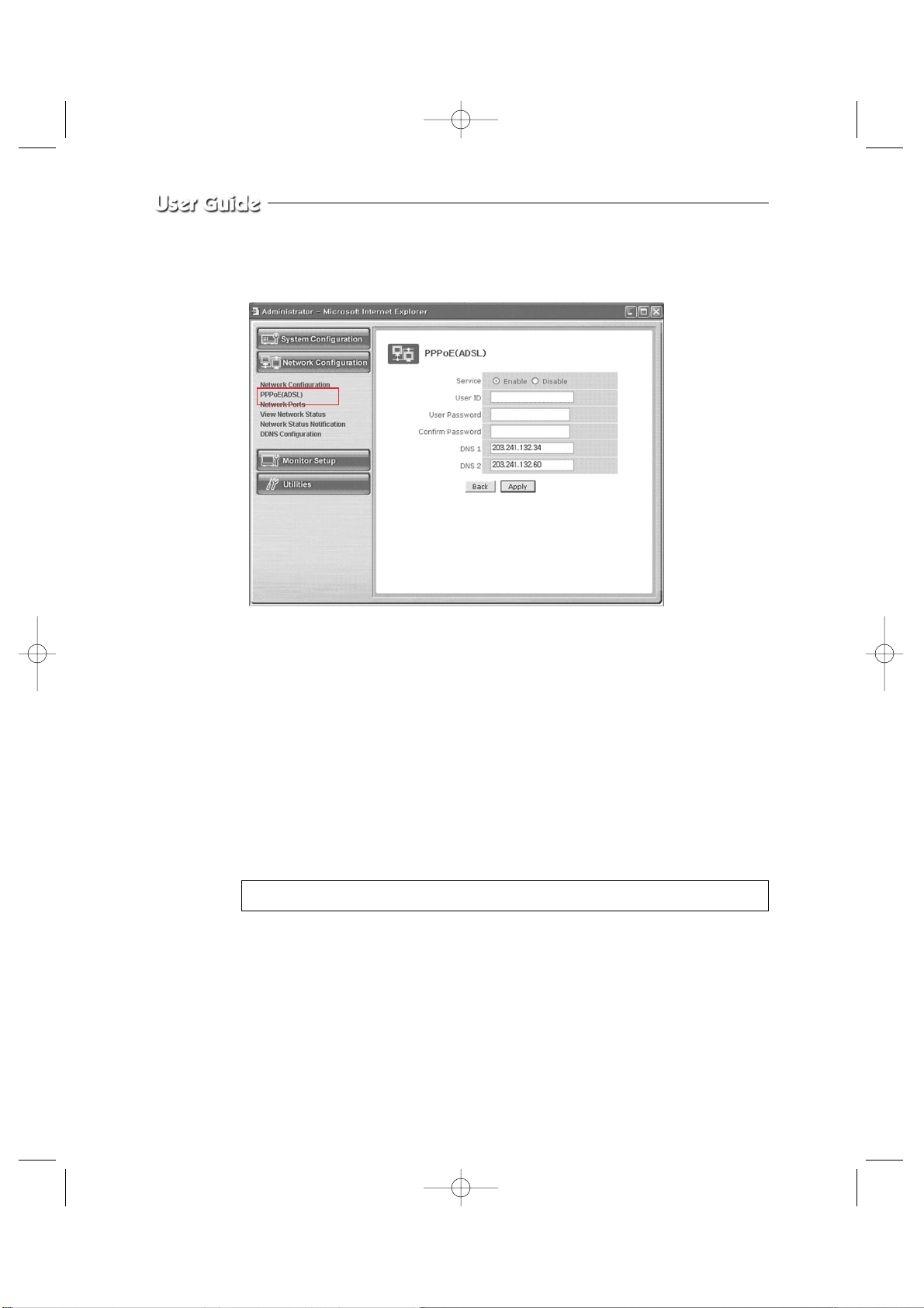
2. PPPoE (ADSL) for Eth0
1) Service : Decide if you want to try PPPoE Connection or not.
2) User ID : User’s ID that is registered in th ISP.
3) User Password : User’s password that is registered in the ISP.
4) Confirm Password : Confirm the password.
5) DNS (Domain Name Service) : Service to convert a Domain Name (ex. www.yahoo.com)
into an IP address (ex. 216.109.127.28).
The SSC21WEB Server uses this service to join the FTP
server or other webs by the Domain Name.
ADSL service supports only PPPoE (Point to Point over
the Ethernet).
* Note : When connecting ADSL, ID & PASSWORD shall be limited within 40 characters.
DNS is a default value, so it does not need to change except a special case.
SSC21WEB-3 2004.8.25 6:42 PM Page 66
Page 67
Eng-67
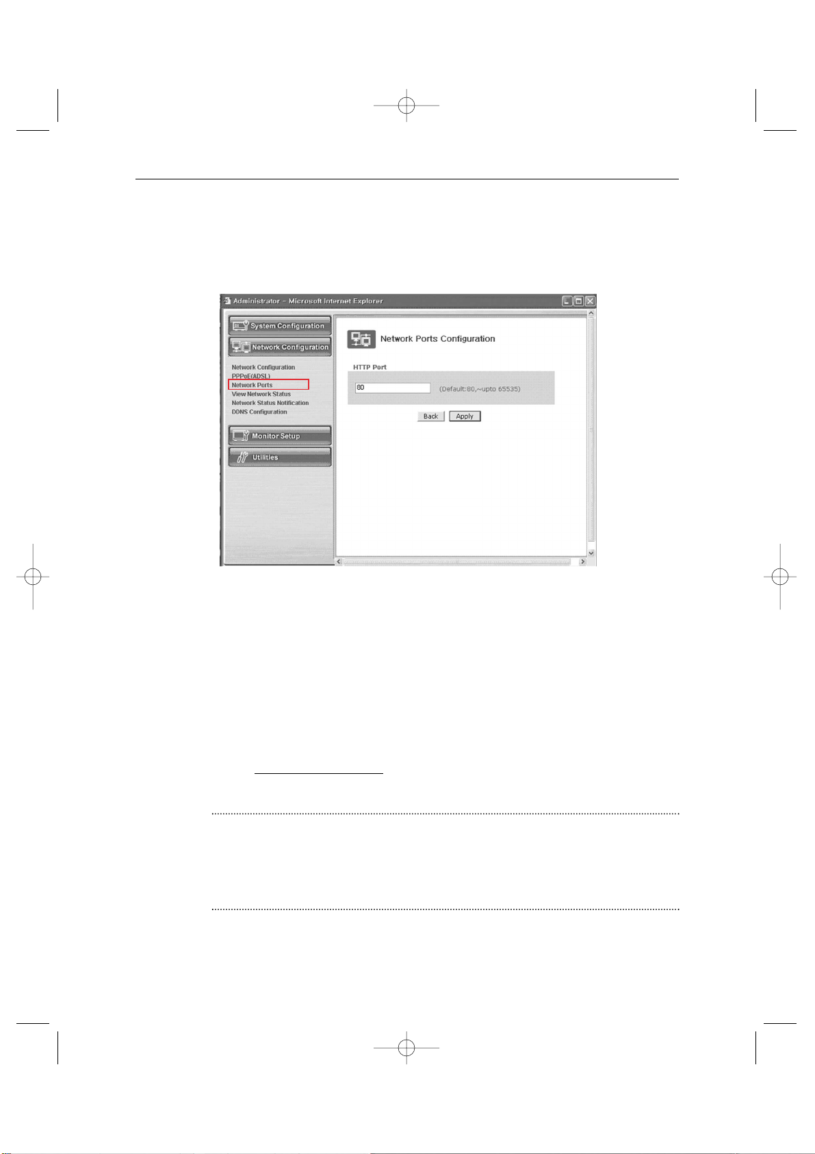
3. Network Ports Configuration
It sets the HTTP Port number to use when the SSC21WEB Server communicates with a
Client PC.
The present SSC21WEB Server uses HTTP Port (80).
- HTTP Port
1) This is the port the Client PC uses to connect to the web page of the SSC21WEB Server.
Depending on the environment of the network, its value can be varied.
2) The fault values is 80 and it can be assigned up to 65535 maximum.
* If you change the value of the HTTP Port, you should type in the new one with the address
of the SSC21WEB Server in the address window of the web browser.
(Ex. If the IP address of the SSC21WEB Server is 192.168.1.100 and the HTTP Port :
8080, http://192.168.1.100:8080
.)
3) Click Apply button to apply the present setting.
CAUTION
Set the port be used when connecting to SSC21WEB in internet Explorer.
The port setting is used for various network configuration when avoiding the network
where firewall constitutes or a particular port Etc.
SSC21WEB-3 2004.8.25 6:43 PM Page 67
Page 68
Eng-68
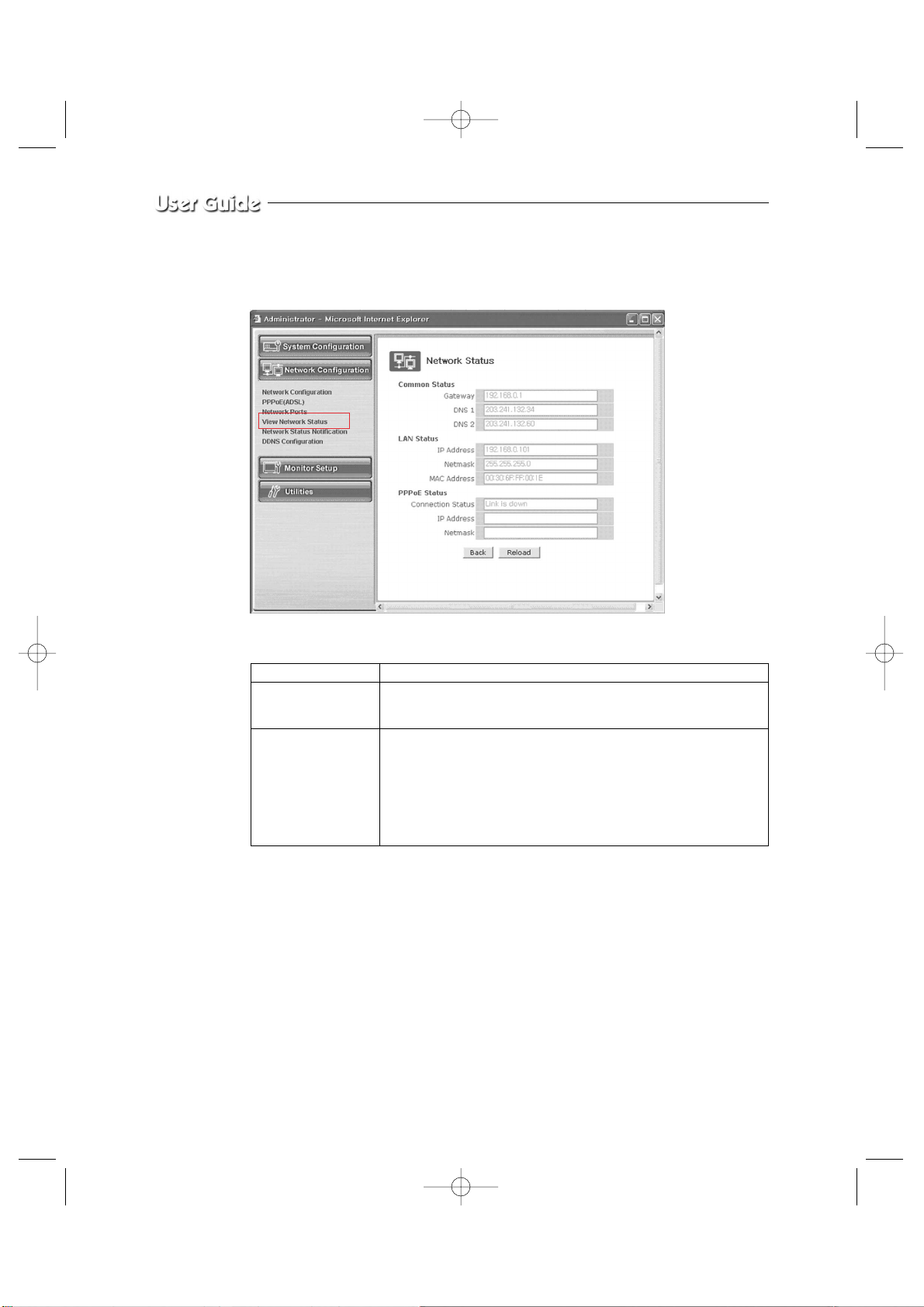
4. View Network Status
This is a menu to see the general status of the network setting of the SSC21WEB Server.
- Menu Configuration
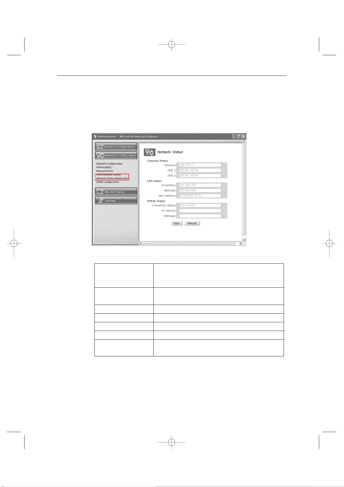
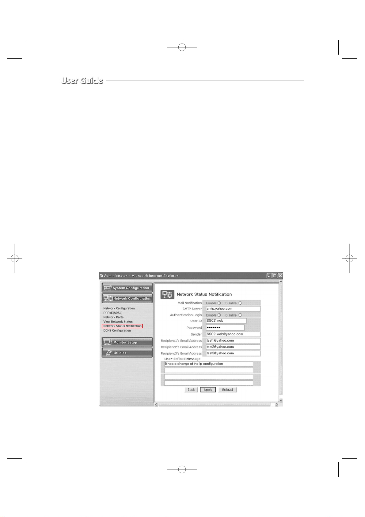
5. Network Status Notification
When there is a change in the setting status of the SSC21WEB Server, it sends e-mails to the
people who want it. Set Mail Notification to “Enable” to send the network setting status of
the SSC21WEB Server to the specified e-mail addresses in the cases as follows.
There are some conditions required for this setting.
Common Status It is to check the status of the Gateway, DNS 1, and DNS 2.
LAN Status It is to check the status of the STATIC IP Address, Netmask, and
MAC Address.
PPPoE Status If the PPPoE service is in the connection status, “Link is up”.
At this time, the service IP and NETMASK can be also checked.
If the PPPoE service is not in the connection status, “Link is
down”.
The existing setting will be recalled if you press Reload button.
SSC21WEB-3 2004.8.25 6:43 PM Page 68
Page 69
Eng-69
1) DHCP Client has been set in “Network Configuration” menu and an IP has been assigned
from the actual DHCP Server to make communication possible.
2) PPP Client has been set in “PPPoE” menu and communication has become possible
through the connection with ISP or PPP Server.
- Menu Configuration
Network Status Notify Configuration
click “Network Status Notify” in the Network Configuration group.
Mail Notification E-mail forwarding or not.
Enable : Forward E-mails.
Disable : Doesn’t forward E-mails.
SMTP Server Type in the address of the server that provides e-mail relay
function.
Authentication Login Shows if the ISP has an authentication for the use of SMTP.
User ID ID for Authentication Login
Password Password for Authentication Login
Sender(Email Address) Type in the addresses of the sender.
Recipient1’s Type in the addresses of the recipients.
Email Address (3 addresses maximum.)
SSC21WEB-3 2004.8.25 6:44 PM Page 69
Page 70
Eng-70
Choose to use the Mail Notification function or not. Choose “Enable” if you want to
notify the network status of the SSC21WEB Server to the people who want through
e-mails.
Type the address of the SMTPServer.
* SMTP Server plays a part as a relay that receives the mail of the user and
delivers it to the receiver.
Set “Authentication Login” to Enable and type in the ID and password assigned from
the SMTP server.
Type the e-mail address of the person who receives the E-mail. Maximum 3 people can
receive the mail.
Type the message you want to add in “User Defined Message”.
After completing setting, click Apply button.
If you click the reset button, it will return to the latest setting.
EX) When user who has an e-mail address ([email protected]) and
password(123456) in YAHOO sets “Alarm Notification” in order to send a mail to
[email protected]...
SSC21WEB-3 2004.8.25 6:44 PM Page 70
Page 71
Eng-71
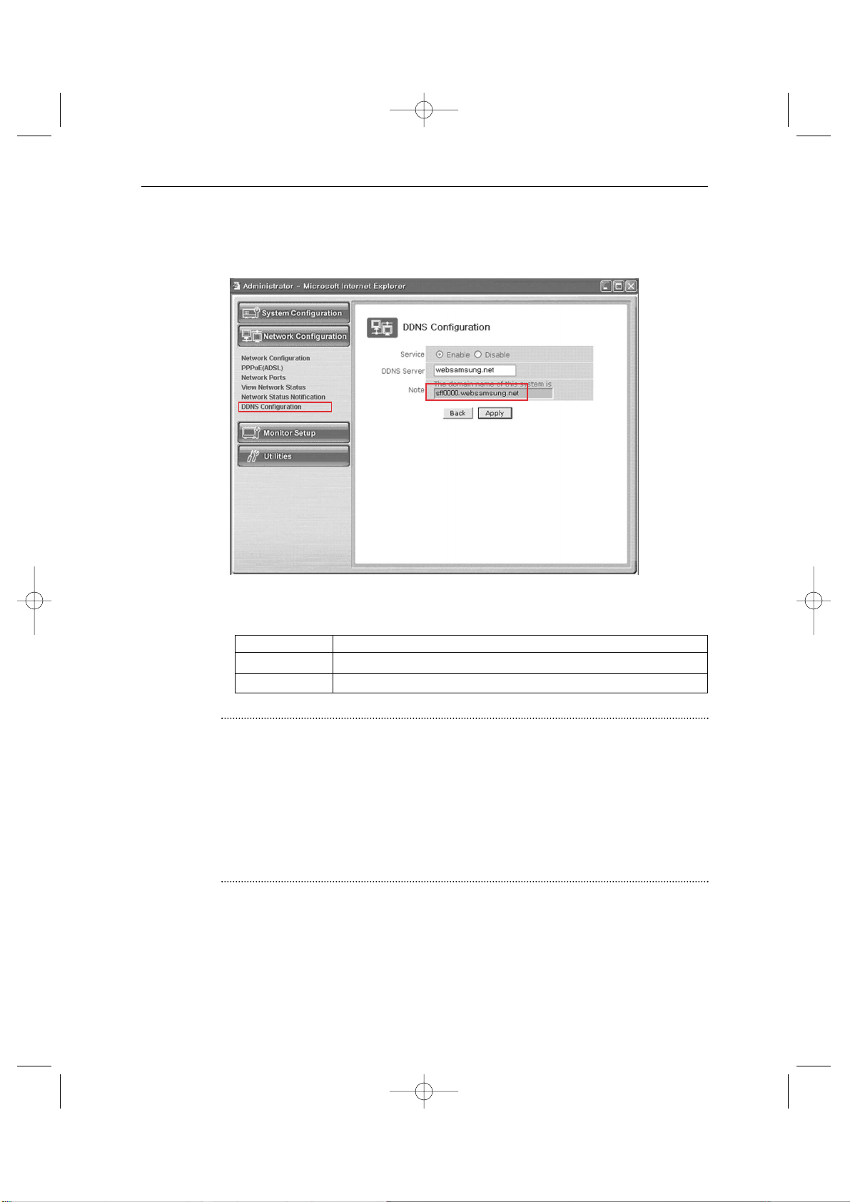
6. DDNS CONFIGURATION
- Menu Configuration
CAUTION
In case of a configuration using DHCP, as the connection to SSC21WEB is made using
domain names (EX : http://sff0000.websamsung.net) that are automatically registered in our
DDNS server, IP address, Subnet Mask and Gateway that are in the network tab of Admin
Mode are not necessarily to be inputted.
The proper domain names of SSC21WEB are automatically registered to DDNS server
installed in our company in case of DHCP cable modem connection.
Server Select Enable or Disable
DDNS Server Websamsung.net
Note The domain name of this system is sff0000.websamsung.net
SSC21WEB-3 2004.8.25 6:44 PM Page 71
Page 72
Eng-72
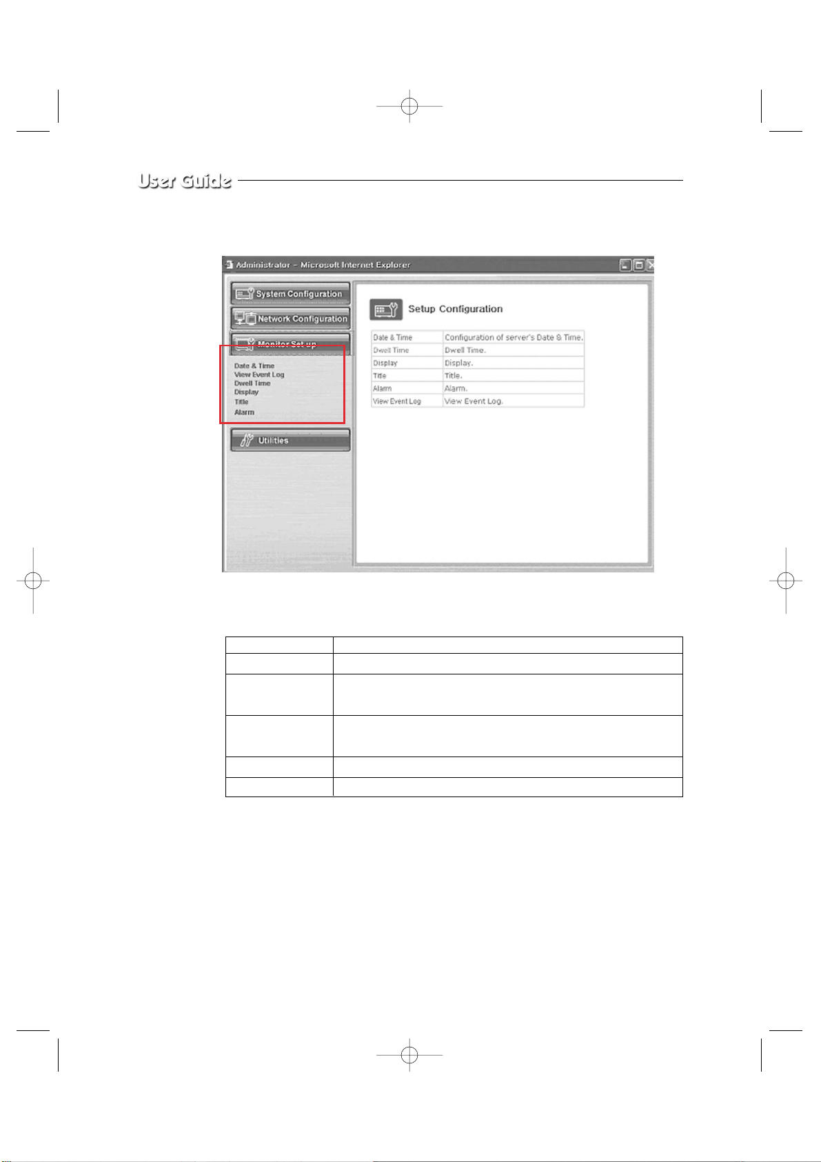
3-8-4) Monitor Set up
- Menu Configuration
Please refer to the CHAPTER3 of the user’s manual.
Date & Time Set the display data format and current time.
View Event Log Display the time and data of camera event and type of event
Dwell Time Displays each picture for pre-set time and automatically Switches
it to the next picture at SEQUENTIAL DISPLAY MODE.
Display Allows users to select the color and ON/OFF of borderline at
QUAD DISPLAY
Title Set the title of each camera at your discretion
Alarm Allows users to set the ALARM MODE for each camera
SSC21WEB-3 2004.8.25 6:44 PM Page 72
Page 73
Eng-73
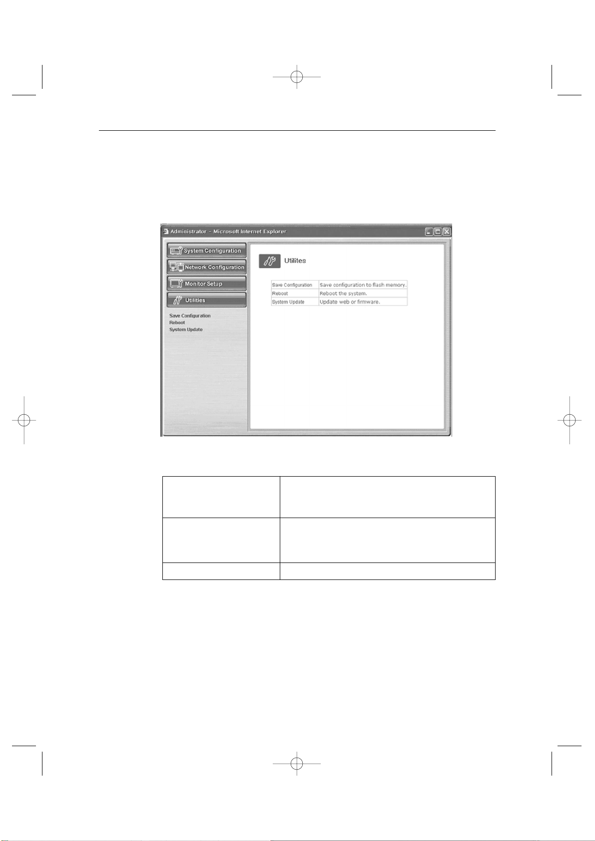
3-8-5) Utilities
This menu is for the flash memory’s update, rebooting, restoring to the basics, and system
upgrade.
- Menu Configuration
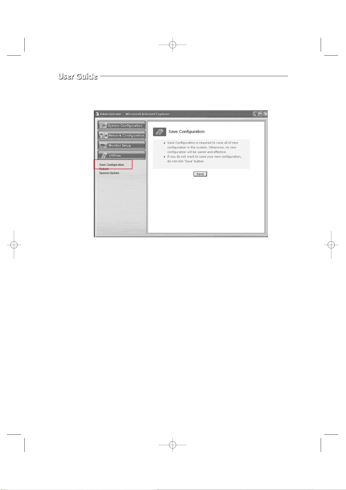
Save Configuration Save Configuration is required to save all of new config-
uration in the system. Otherwise, no new configuration
will be saved effective.
Reboot System reboot is highly and strongly recommended to
applied all new configurations properly to the
SSC21WEB system
System Update System Update
SSC21WEB-3 2004.8.25 6:45 PM Page 73
Page 74
Eng-74
1. Save Configuration
This menu is to save all of the present setting in the Flash Memory.
If you changed any of the setting for the SSC21WEB, it is recommended that you save it in
the Flash Memory in this menu.
SSC21WEB-3 2004.8.25 6:45 PM Page 74
Page 75
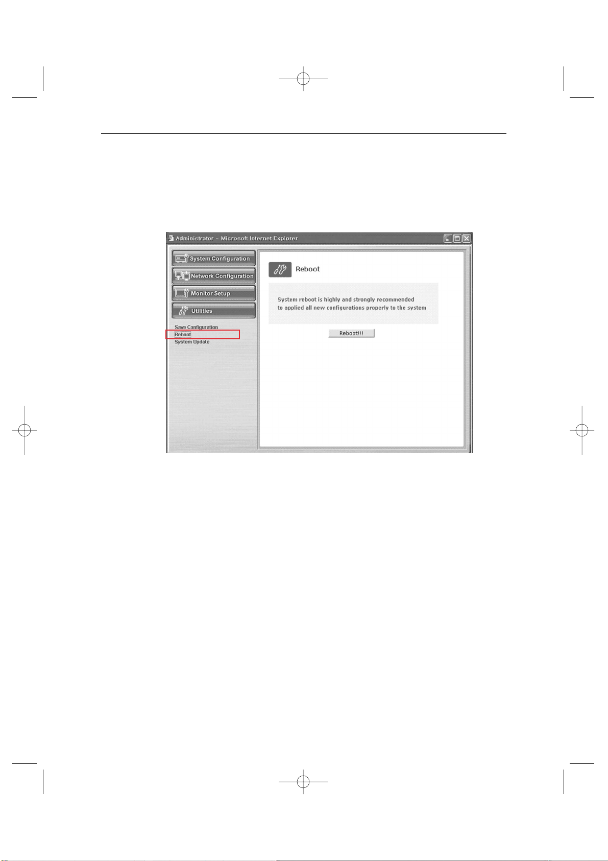
Eng-75
2. Reboot
This menu is for the rebooting of the system. It is better to reboot the system if you change
the setting and update the flash.
1. Click “Reboot” in the utilities group.
2. Click “Reboot!!!”.
SSC21WEB-3 2004.8.25 6:45 PM Page 75
Page 76
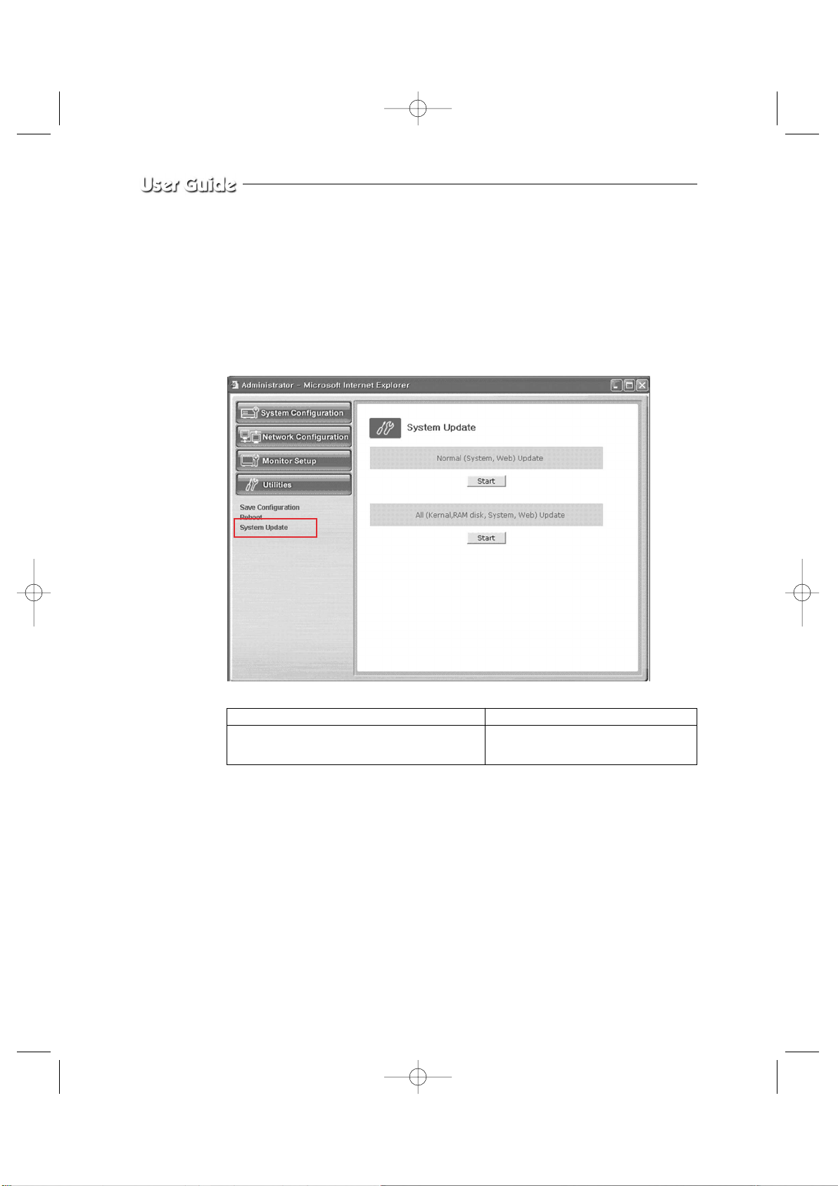
Eng-76
4. System Update
This menu is to update the inner programs and data of the SSC21WEB Server. They are
recorded in the Flash Memory and composed of 4 parts called Kernel Image, Ram disk
Image, System Image, and Web Image respectively.
Each image file should be stored in the user’s PC for update.
Depending on the range you want to update, press the start button properly.
4-1. Normal (System and Web) Update
When you click the start button located in the right side of “Normal (System and Web)
Update”, a window will appear to ask if you want to update.
Click “Cancel” to stop updating. Click “OK” to proceed updating.
Other processes are same as the process of “All Update”. (Excluding the update of Kernel
and RAM disk)
After completing the update, click the reboot button to reboot the system.
Normal (System and Web) Update Update only the System Web.
All (Kernel, RAM disk, System, Web) Update Update all 4 images of Kernel, RAM
Disk, System, and Web.
SSC21WEB-3 2004.8.25 6:46 PM Page 76
Page 77
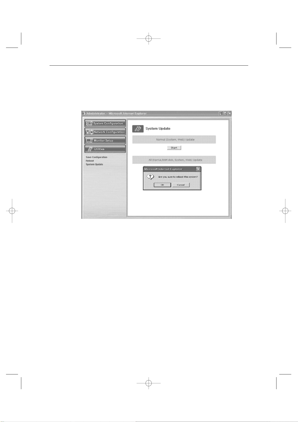
Eng-77
4-2. All (kernel, RAM disk, System, Web) Update
When you click the start button located in the right side of “All (Kernel, RAM disk, System,
Web) Update”, a window will appear to ask if you want to update.
Click “Cancel” to stop updating.
1. “OK” to proceed updating.
2. Apop-up window will appear. Choose “Zimage” in the browse.
SSC21WEB-3 2004.8.25 6:46 PM Page 77
Page 78
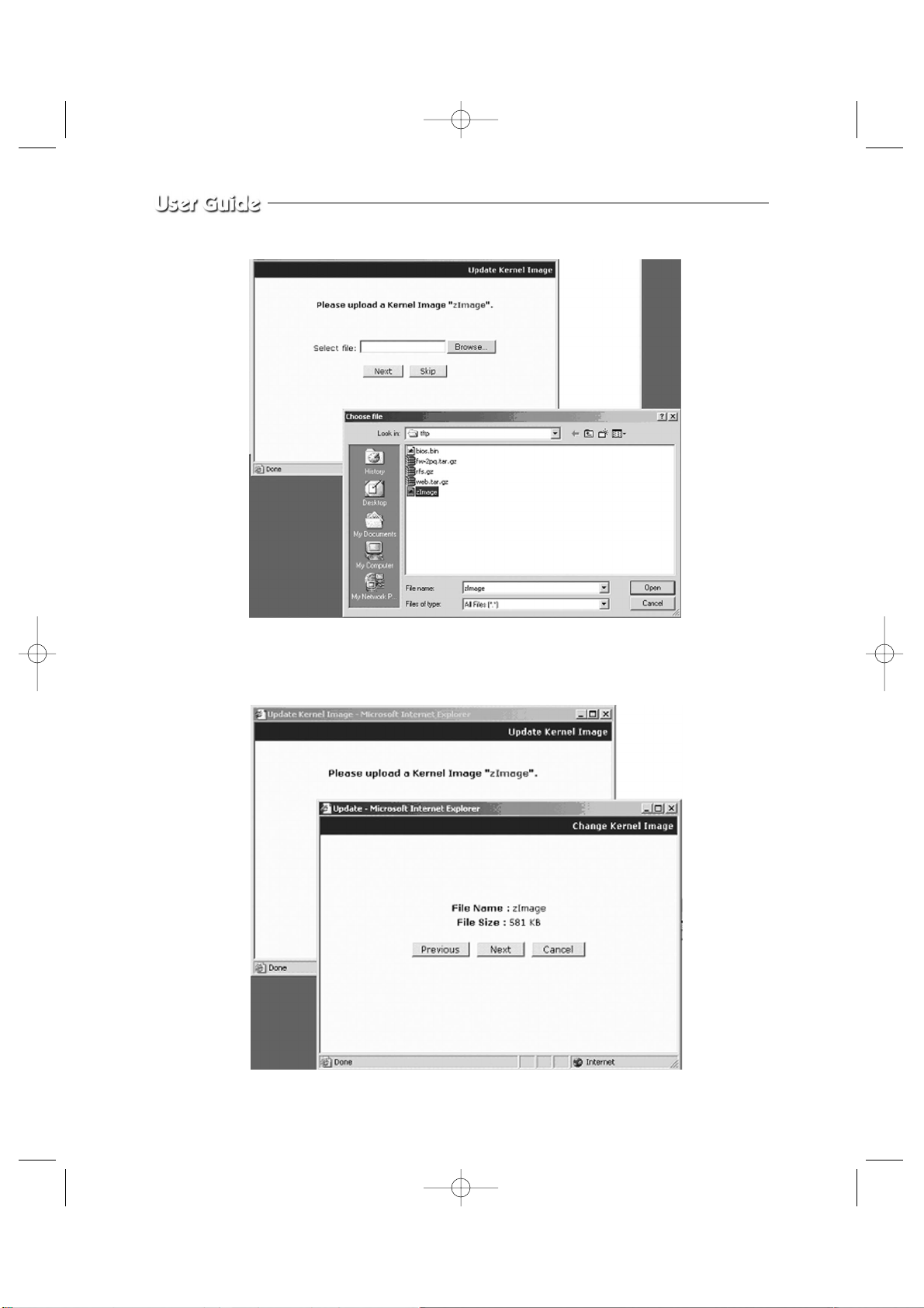
Eng-78
3. Click “Next” button to move to the next stage.
Click “Skip” button to move to the next stage without Kernel Image’s update.
Click “Next” button and a window will appear to check the name and size of the file.
SSC21WEB-3 2004.8.25 6:46 PM Page 78
Page 79
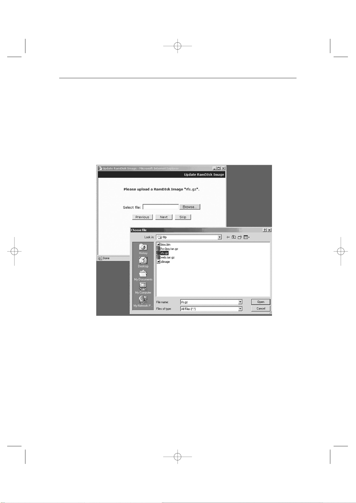
Eng-79
Click “Previous button to go back to the previous stage.
Click the next button to execute update of the program and move to the next stage.
Click the cancel button to stop the update process.
4. In the next stage, a pop-up window will appear for the file searching for the RAM
Disk Update.
Choose “rfs.gz” in the browse.
SSC21WEB-3 2004.8.25 6:47 PM Page 79
Page 80
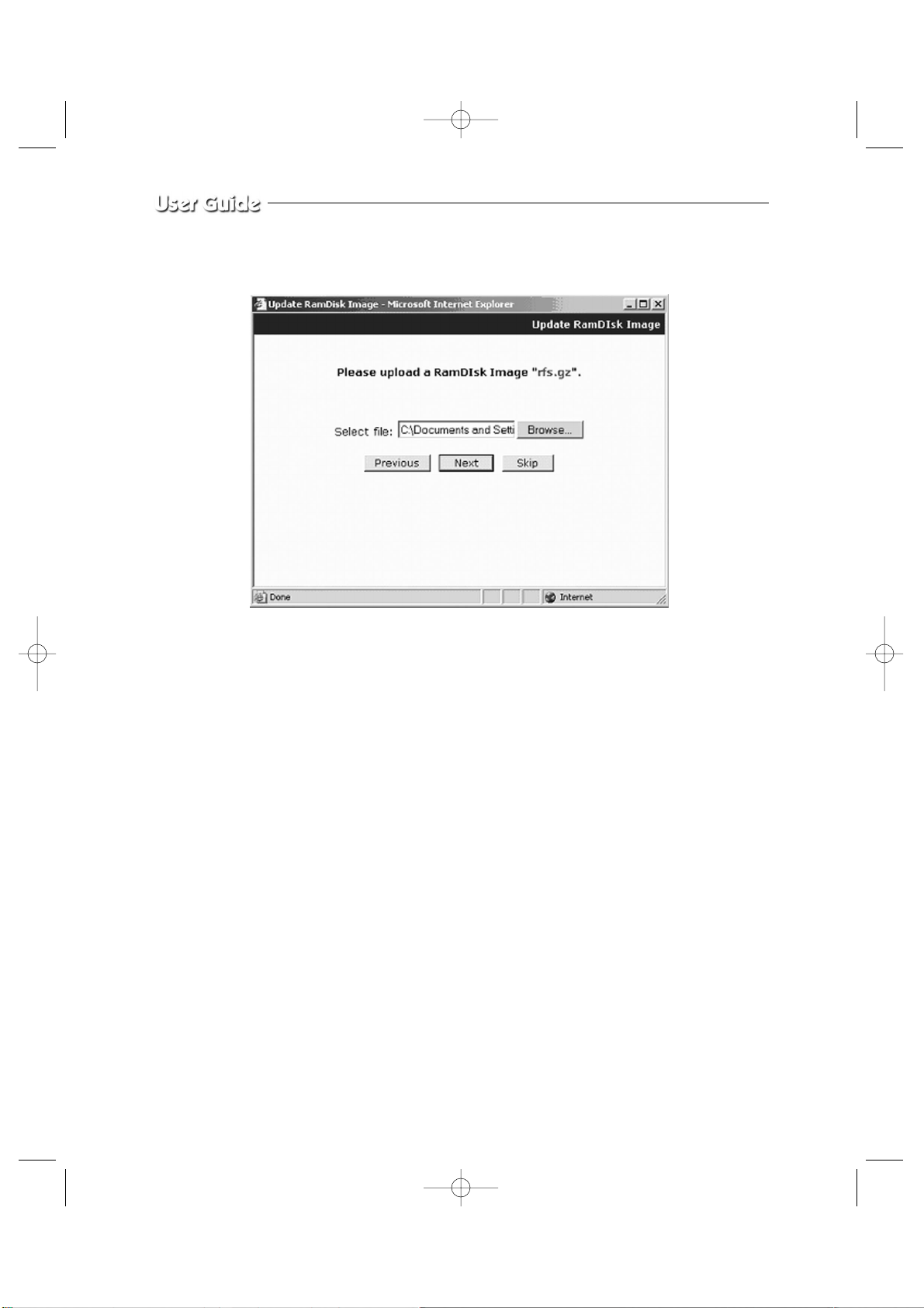
Eng-80
5. Click “Next” button to move to the next stage.
Click “Skip” button to move to the next stage without Kernel Image’s update.
Click “Next” button and a window will appear to check the name and size of the file.
Click “Previous” button to go back to the previous stage.
Click the next button to execute update of the program and move to the next stage.
Click the cancel button to stop the update process.
SSC21WEB-3 2004.8.25 6:47 PM Page 80
Page 81
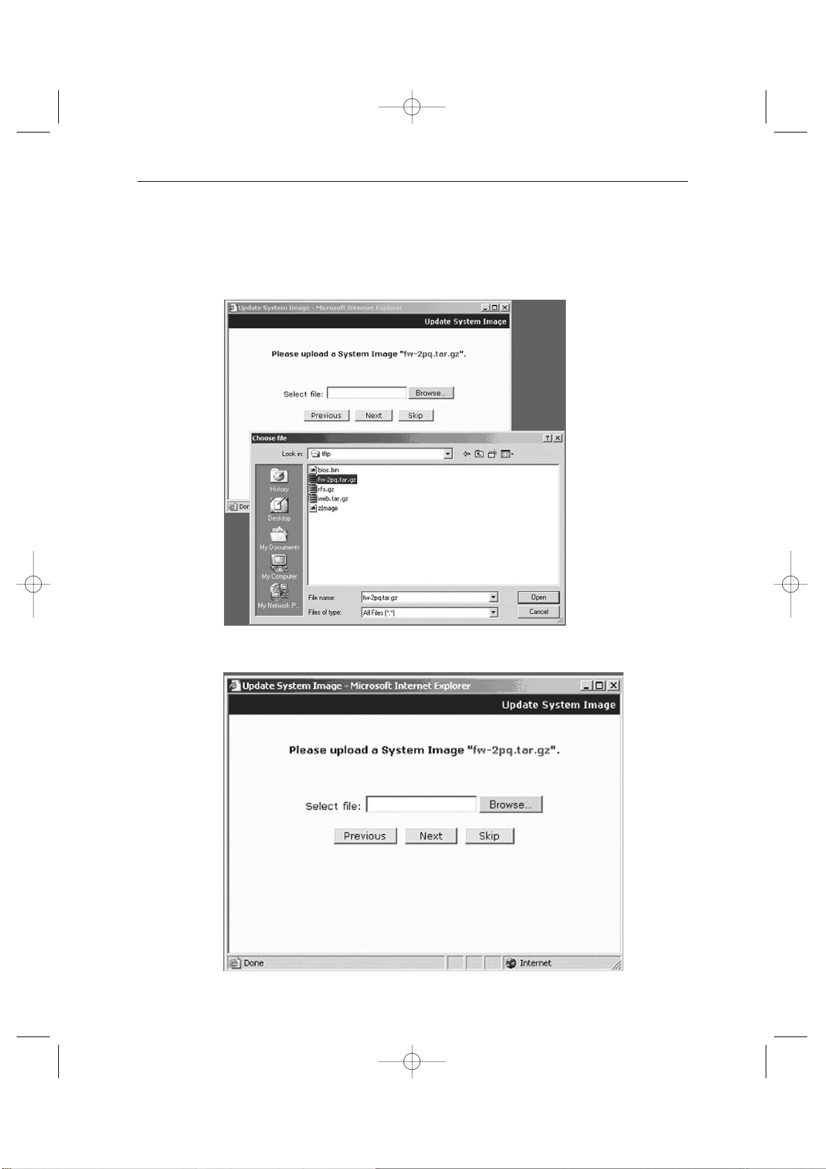
Eng-81
6. In the next stage, a pop-up window will appear for the file searching process for the
System Image Update.
Choose “Fw_2pq.tar.gz” in the browse.
7. Click “Next” button to move to the next stage.
SSC21WEB-3 2004.8.25 6:47 PM Page 81
Page 82
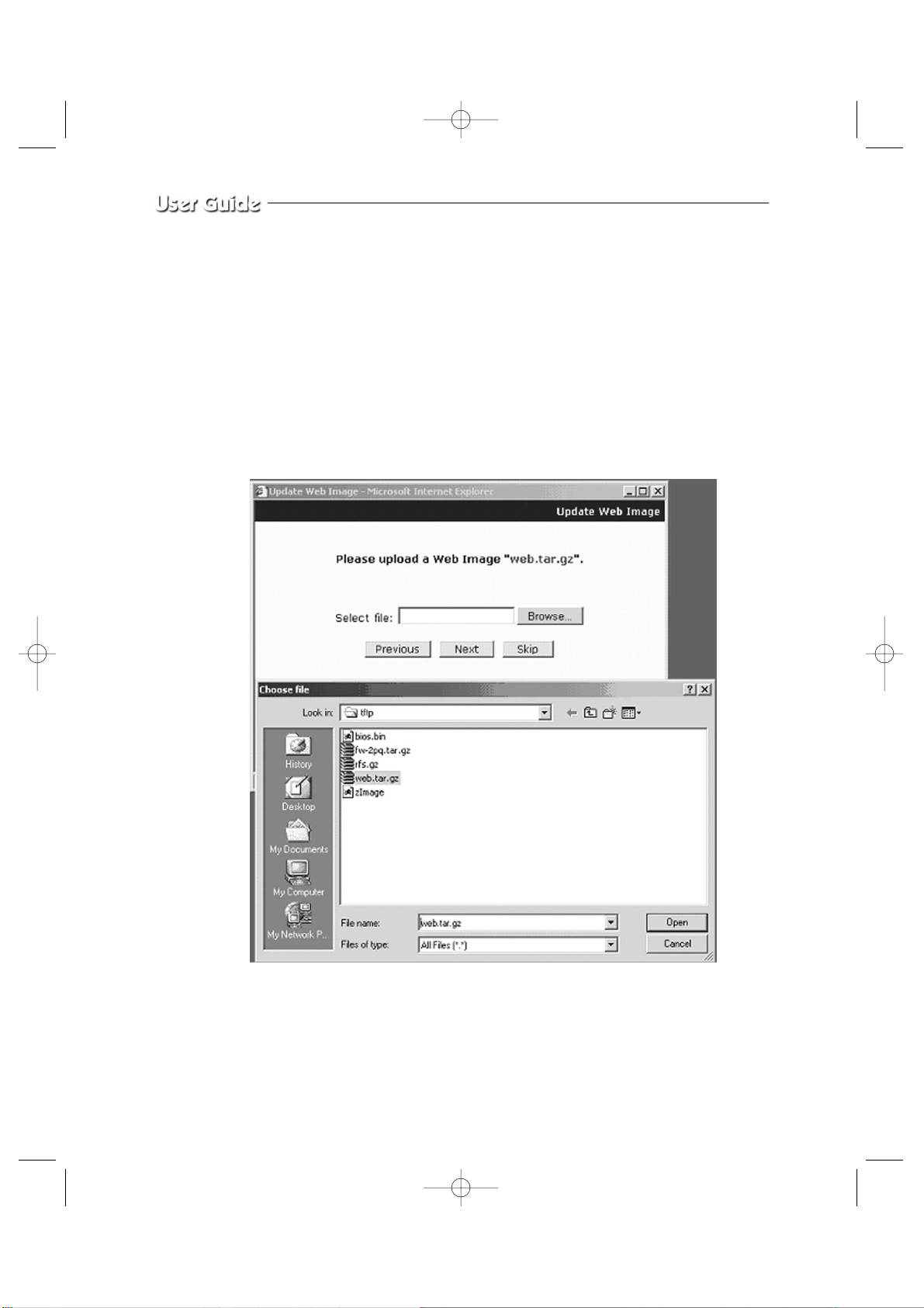
Eng-82
Click “Skip” button to move to the next stage without kernel Image’s update.
Click “Next” button and a window will appear to check the name and size of the file.
Click “Previous” button to go back to the previous stage.
Click the next button to execute update of the program and move to the next stage.
Click the cancel button to stop the update process.
8. In the next stage, a pop-up window will appear for the file searching process for the
System Image Update. Choose “web.tar.gz” in the browse.
SSC21WEB-3 2004.8.25 6:47 PM Page 82
Page 83
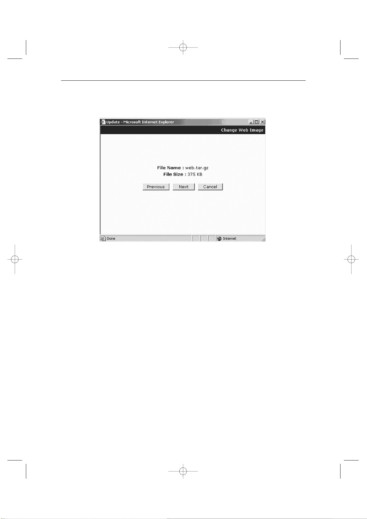
Eng-83
9. Click “Next” button to move to the next stage.
Click “Skip button to move to the next stage without Kernel Image’s update.
Click “Next” button and a window will appear to check the name and size of the file.
Click “Previous” button to go back to the previous stage.
Click the next button to execute update of the program and move to the next stage.
Click the cancel button to stop the update process.
SSC21WEB-3 2004.8.25 6:48 PM Page 83
Page 84
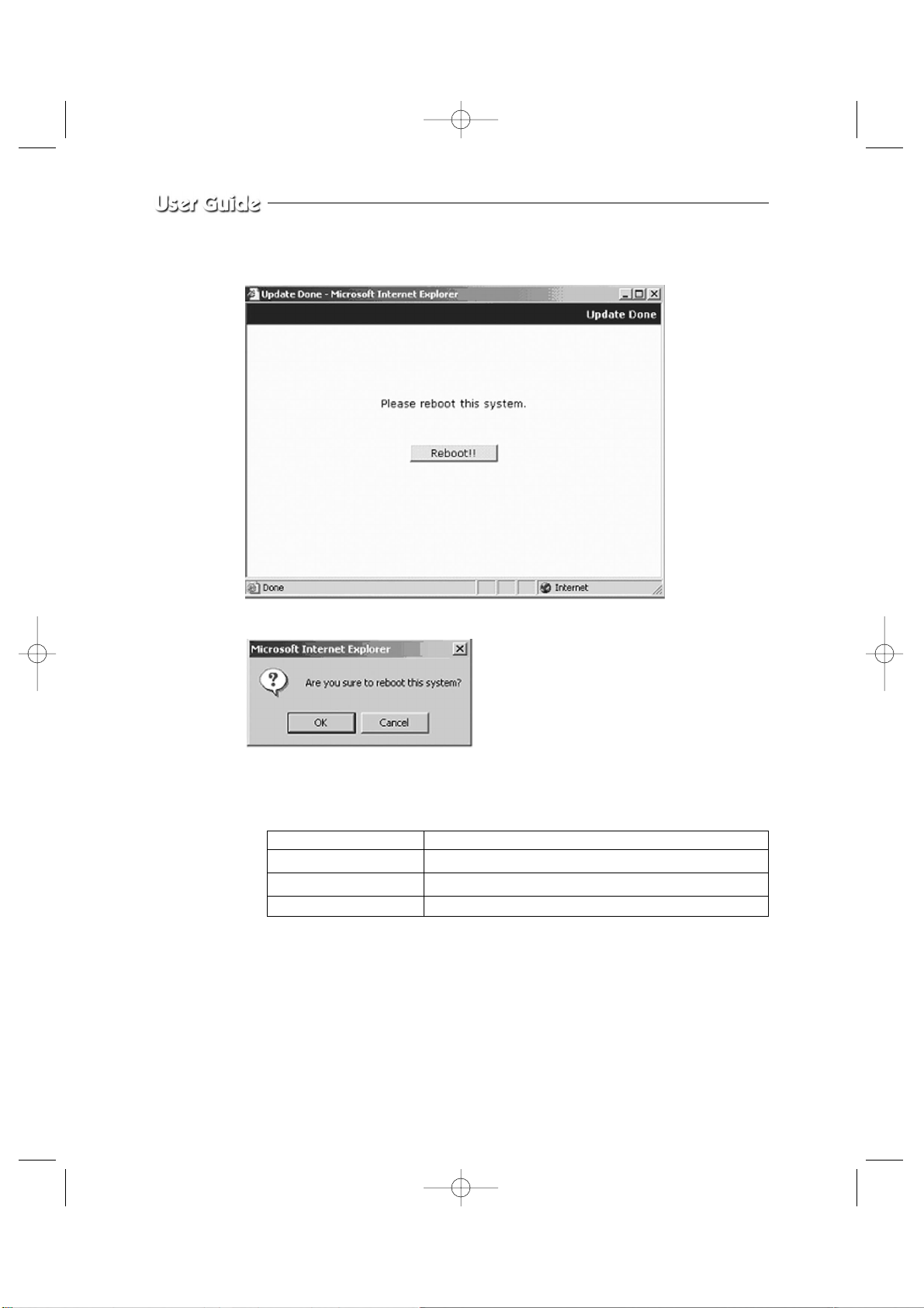
Eng-84
10. Awindow will appear for rebooting after completing all the update processes.
Click the reboot button and press the confirmation button to reboot the system.
11. Close your web browser and wait for about a minute before you log in again
Files relate to the update of SSC21WEB
The window shown as above may not appear if there is a pop-up breaker installed in the
user’s PC. If you update system on a web page, you should stop the pop-up breaker to
proceed.
* Note : Download a picture at http://www.securitysamsung.com
Refer to Appendix A (page 96).
Kernel Image zimage
RAM Disk Image rfs.gz
System Image Fw_2pq.tar.gz
Web page Image web.tar.gz
SSC21WEB-3 2004.8.25 6:48 PM Page 84
Page 85
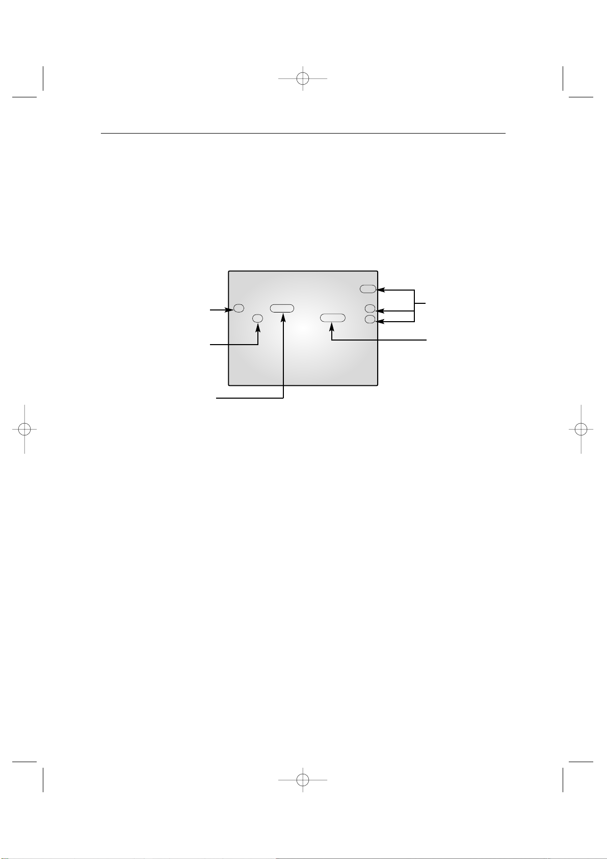
Eng-85
06/01/03 13:14:00
NO CH MM/DD/YY HH:MM:SS EVT
01 07 02/10/03 10:00:30 A
02 01 02/11/03 11:22:00 L
03 01 06/01/03 12:33:01 04 02 06/01/03 13:01:03 05 01 --/--/-- --:--:-- 06 01 --/--/-- --:--:-- 07 01 --/--/-- --:--:-- 08 01 --/--/-- --:--:-- -
3-9) VIEW EVENT LOG MENU function and setting method
• Function: Displays the time and date of camera event and type of event.
• Setting method:Move to #7. VIEW EVENT LOG MENU by using œœENTER
√√
SWITCH at SETUP MENU, then press the ENTER SWITCH to display the OSD as
shown in the figure below. (The figure shows the initial setting status.)
An event which occurred most recently is recorded with first priority, then users can move to
the next page by using œœENTER√√SWITCH. ATotal of 64 events can be listed.
* Note : IF you press the FREEZE key and the SEQUENCE key at the same time, all event
lists will be erased.
Type of event happening
L : LOSS
A : ALARM
Sequence of
event happening
Time of event happening
Camera No.
that event
happened.
Date of event
happening
SSC21WEB-3 2004.8.25 6:48 PM Page 85
Page 86
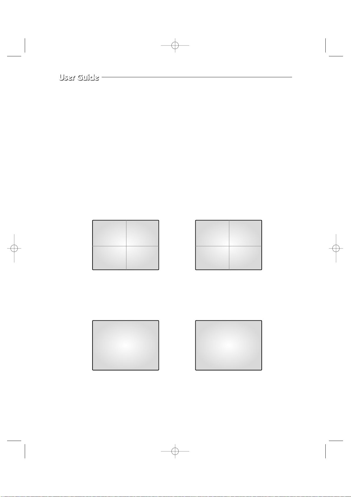
Eng-86
Chapter 4: DISPLAY MODE setting method
4-1) SINGLE SCREEN DISPLAY
Initial display mode of monitor is QUAD A. In case users want to see the camera image at
full mode, select a target camera by turning œœENTER√√SWITCH left and right. After that,
press the ENTER SWITCH and selected camera image will be displayed at full screen. If
users turn the œœENTER
√√
SWITCH left / right at SINGLE DISPLAY MODE at this time,
they can see another camera image at full screen. For example, when users want to see CH1
at FULL MODE after SINGLE -displaying CH2 at QUAD A, please follow the instructions
below.
06/01/03 13:14:00
CH1 CH2
CH3 CH4
QUAD A
INITIAL DISPLAY STATUS
QUAD A
➯
➯
CH1
➯
Select CH2 by turning œœENTER
√√
SWITCH
FULL SCREEN DISPLAY of CH2FULL SCREEN DISPLAY of CH1
Press œœENTER
√√
SWITCH after
selecting CH2
Display CH1
by turning
œœ
ENTER
√√
SWITCH
06/01/03 13:14:00
06/01/03 13:14:0006/01/03 13:14:00
CH1 CH2
CH1 CH2
CH2
SSC21WEB-3 2004.8.25 6:48 PM Page 86
Page 87
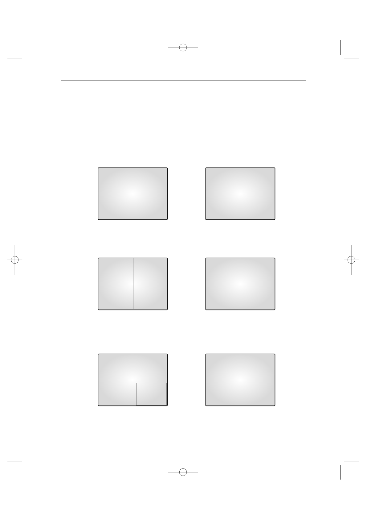
Eng-87
4-2) QUAD MODE DISPLAY
Users can switch SINGLE DISPLA YMODE and SEQUENTIAL DISPLAYMODE to QUAD
DISPLAY MODE, or QUAD A (QUAD B) to QUAD B (QUAD A), or PIPMODE to QUAD
MODE, press the QUAD/PAGE KEY.
* At QUAD MODE display from SINGLE MODE or SEQUENCE MODE,
CH3
CH3 DISPLAY QUAD MODE DISPLAY
of QUAD A
06/01/03 13:14:00
QUAD A
➯
QUAD A QUAD B
➯
CH 3 CH 1
PIP MODE DISPLAY
QUAD A
➯
Press
QUAD/Page
KEY
QUAD MODE DISPLAY
of QUAD A
QUAD MODE DISPLAY of
QUAD B
QUAD MODE DISPLAY of
QUAD A
Press
QUAD/Page
KEY
Press
QUAD/Page
KEY
* At QUAD B(QUAD A) display from QUAD A(QUAD B),
* At QUAD B(QUAD A) display from PIP MODE,
06/01/03 13:14:00
06/01/03 13:14:00
06/01/03 13:14:00
CH1 CH2
CH3 CH4
CH5 CH6
CH7 CH8
06/01/03 13:14:00
06/01/03 13:14:00
CH5 CH6
CH7 CH8
CH1 CH2
CH3 CH4
SSC21WEB-3 2004.8.25 6:48 PM Page 87
Page 88
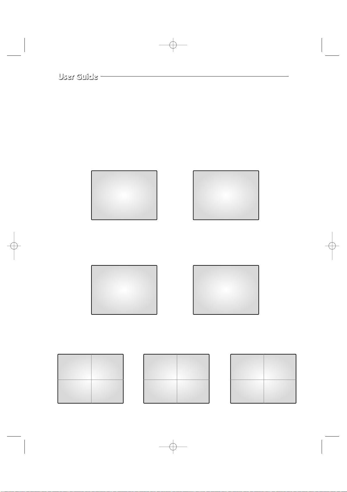
Eng-88
4-3) AUTO SEQUENTIAL DISPLAY MODE
Pressing on the SEQUENCE KEY on the front allows screen to automatically switch to
SINGLE MODE full screen or QUAD MODE. (‘no-signal’ channels will be skipped while
single screen is auto-switching.)
If the DWELL TIME SETTING of SETUP MENU is set to 3 seconds and the SEQUENCE
KEY is pressed at this time, the operation will be carried out as follows.
CH 2 CH 3
➯
➯
CH 1 CH 4
➯
Press SEQUENCE KEY
when CH2 is displayed
at full screen
Automatic sequential switching to CH3
Automatic sequential switching to CH4Automatic sequential switching to CH1
In 3 seconds
In 3 seconds
In 3 seconds
06/01/03 13:14:00
06/01/03 13:14:00
06/01/03 13:14:00
06/01/03 13:14:00
* QUAD MODE SEQUENCE DISPLAY
* SINGLE MODE SEQUENCE DISPLAY
QUAD A QUAD B
➯➯
06/01/03 13:14:00
06/01/03 13:14:00
CH5 CH6
CH7 CH8
CH1 CH2
CH3 CH4
QUAD A
06/01/03 13:14:00
CH1 CH2
CH3 CH4
SSC21WEB-3 2004.8.25 6:48 PM Page 88
Page 89
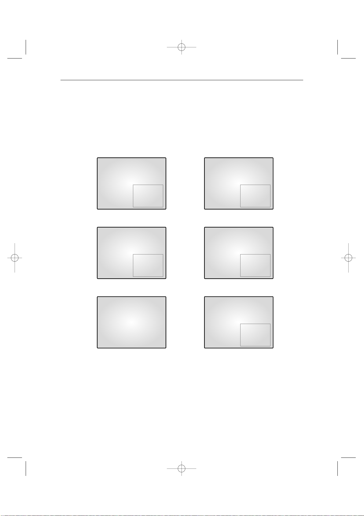
Eng-89
4-4) PIP MODE DISPLAY
Can be used to see PIP screen in Single screen mode.
If you press the œœENTER
√√
on PIP screen ,the main screen will change. If you press the
œœ
ENTER
√√
to the left and right,the main screen can be transferred to another channel.
Sub-screen location can be selected on DISPLAY MENU in SETUP MENU.
CH1 CH3
➯
CH3 CH1
CH1 CH3
➯
CH2 CH3
CH1
➯
CH2 CH3
Under PIP DISPLAY
Main and Sub screen is switched
Under PIP DISPLAY
Main screen is switched
Under single screen display
Main and Sub screen is displayed
as set at the DISPLAY MENU of
SETUP MENU
Press
œœ
ENTER
√√
KEY
Turn
œœ
ENTER
√√
SWITCH right
Press PIP KEY
06/01/03 13:14:00 06/01/03 13:14:00
06/01/03 13:14:00 06/01/03 13:14:00
06/01/03 13:14:00 06/01/03 13:14:00
SSC21WEB-3 2004.8.25 6:48 PM Page 89
Page 90
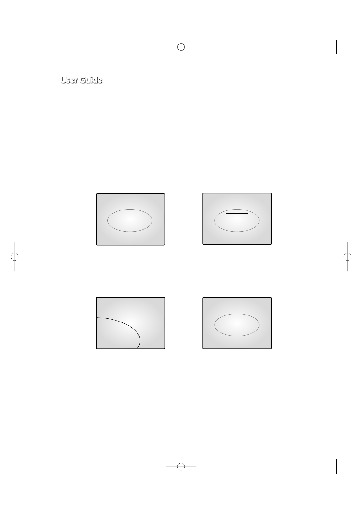
Eng-90
4-5) ZOOM MODE DISPLAY
When users want to see zoomed image of a specific area of the display, press the ZOOM
KEY in the front to display zoom selection area. Select zoom target area by turning
œœ
ENTER√√SWITCH left and right, and press the ENTER SWITCH, then, the selected area
will be displayed at full single mode with zoomed area doubled. At zoom function operation
at SINGLE DISPLAY MODE (CH2), the operation will be carried out as shown in figure
below. (Zoom selection areas at SINGLE DISPLAY MODE are nine.)
CH2
CH2
➯
➯
➯
CH2
CH2 SINGLE DISPLAY
ZOOM area is activated.
Press ZOOM
KEY
The selected area will be doubled
and at FULL DISPLAY.
Turn
œœ
ENTER
√√
SWITCH and
move to desired location
Press
œœ
ENTER
√√
SWITCH
06/01/03 13:14:00 06/01/03 13:14:00
06/01/03 13:14:00 06/01/03 13:14:00
SSC21WEB-3 2004.8.25 6:48 PM Page 90
Page 91

Eng-91
Chapter 5: Each product feature
SOD14C : Standard Camera
Model Name
Broadcasting System
Imaging Device
Effective Pixels S
Synchronization
Resolution
Signal Output
S/N Ratio
Minimum Scene Illumination
Gamma Correction
Lens
Auto Exposure
Audio
I/O Connectors
Operating Temperature
Power Source
Power Consumption
Dimensions
Weight
SOD14C
NTSC STANDARD
1/4 ”SUPER HAD IT CCD
510(H) x 492(V)
Internal
H :330 TV Lines, V: 350 TV Lines
VBS 1.0Vp-p(75ohms composite)
≤ 48 dB
2lux(F2.0, 50 IRE)
0.45
Focal Length (f) : 3.8mm, Aperture Ratio (F) : 2.0
Electronic Shutter lris
-40dB Condenser Microphone Inclusion
Modular jack
-10 ~ +50 °CC
DC 12V
Approx. 2W
57(W) x 47.2(H) x 100.5(L)
150g
SSC21WEB-3 2004.8.25 6:48 PM Page 91
Page 92

Eng-92
Video Input
Video Output
Audio Input
Audio Output
Alarm/Motion Features:
Connected to Alarm
Box/Camera
Sequence
Event List
Display mode
Horizontal Resolution
Operation Temperature
CRT
Dimension (W x D x H (mm))
Weight
Power consumption
Video system
High Voltage (KV)
Operation Humidity Range
AC Input Ranges
Audio Output[watt]
• CAMERA8 Input: 1.0Vp-p(CVBS), 75Ω (vertical)
• VCR 1 Input (to Video Out of VCR) : 1.0Vp-p, 75Ω (vertical)
• BNC 4 Output: 1.0 Vp-p, 75Ω (vertical), S-Jack Type, CVBS
• VCR 1 Output: 1.0 Vp-p, 75Ω (vertical), S-Jack Type, CVBS
• CAMERA8 Input:
• VCR 1 Input (to Audio Out of VCR) : S-Jack Type
• CAMERA8 Input:
• VCR 1 Output: S-Jack Type
A/O (HOT, COLD) : Relay Active
A/R (Alarm Reset) : Open Collector “L” Level,
Pulse Width =150ms or above
Alarm Hold Time : Select 5 sec, 15 sec, 30 sec, 1 min, 3 min,
5 min, 10 min, 20 min, 30 min..
Select between 01 sec to 30 sec.
(max) 64 case
Single mode, Quad Amode, Quad B mode, PIP, Sequence
Freeze, Zoom(X2)
350 TV Lines or more (Live Mode Full Screen)
0 °C ~ 40 °C
21” FLAT CRT
(MONITOR)520 x 509 x 486, (PACKING)655 x 640 x 771
(MONITOR) 28.0Kg, (PACKING) 39.5Kg
110W
NTSC VIDEO SYSTEM
28 ±2.0
0~90%
AC 120V, 60Hz
1.5W
OBSERVATION MONITOR (SSC21WEB)
SSC21WEB-3 2004.8.25 6:48 PM Page 92
Page 93

Eng-93
SSC21WEB NETWORK
•
32bit Embedded Processor
•
Flash Memory : 8Mbytes
•
SDRAM : 32Mbytes
•
HTTP, TCP/IP, FTP, Telnet, ARP, PPP,
DHCP, PPPoE
•
Compression Algorithm : Real-time M-JPEG
•
Rate : 30 fps for each channel
•
Quality : 3 levels
•
NTSC
•
NTSC, 352x240, 704x240
•
Max 30 Frame Per Second (NTSC)
•
Configuration by serial port or web browser
•
Remote Flash memory update
•
10/100 BaseT Fast Ethernet
•
Password protected server access
•
CPU_Pentium IV 1GHz higher
•
RAM_256MB or higher
•
Video Memory_32MB or higher
•
Resolution_1024x768 or higher
•
OS_Windows 98/ME/2000/XP Service Pack
•
installation recommended
•
Web Brower_Internet Explorer 5.5 or later
Hardware
Network Protocols
Image Compression & Quality
Video Format
Video Resolution
Performance
Management
LAN Interface
Security Function
PC Specification
SSC21WEB-3 2004.8.25 6:48 PM Page 93
Page 94
Eng-94
The system performance may decrease if the computer has lower specification than the recommecdations, is not installed with the latest service pack, or has an illegally installed operation
system(OS).
A unique MAC address is registered to this device.
If the administrator setting and monitoring may not be available due to conflicting unregistered
MAC addresses, please contact a local service center or head office.
SSC21WEB enables users to see up to four viewers on one computer.
The system may malfunction if over five viewers with low performance computers are connected to the device.
After reboot, if you reconnect Network Cable or Internet explorer, then the transmission of the
Motion Images could be delayed with showing “Waiting” message or disconnected under the
environment of WINDOWS 98 and Windows ME.
SSC21WEB-3 2004.8.25 6:48 PM Page 94
Page 95
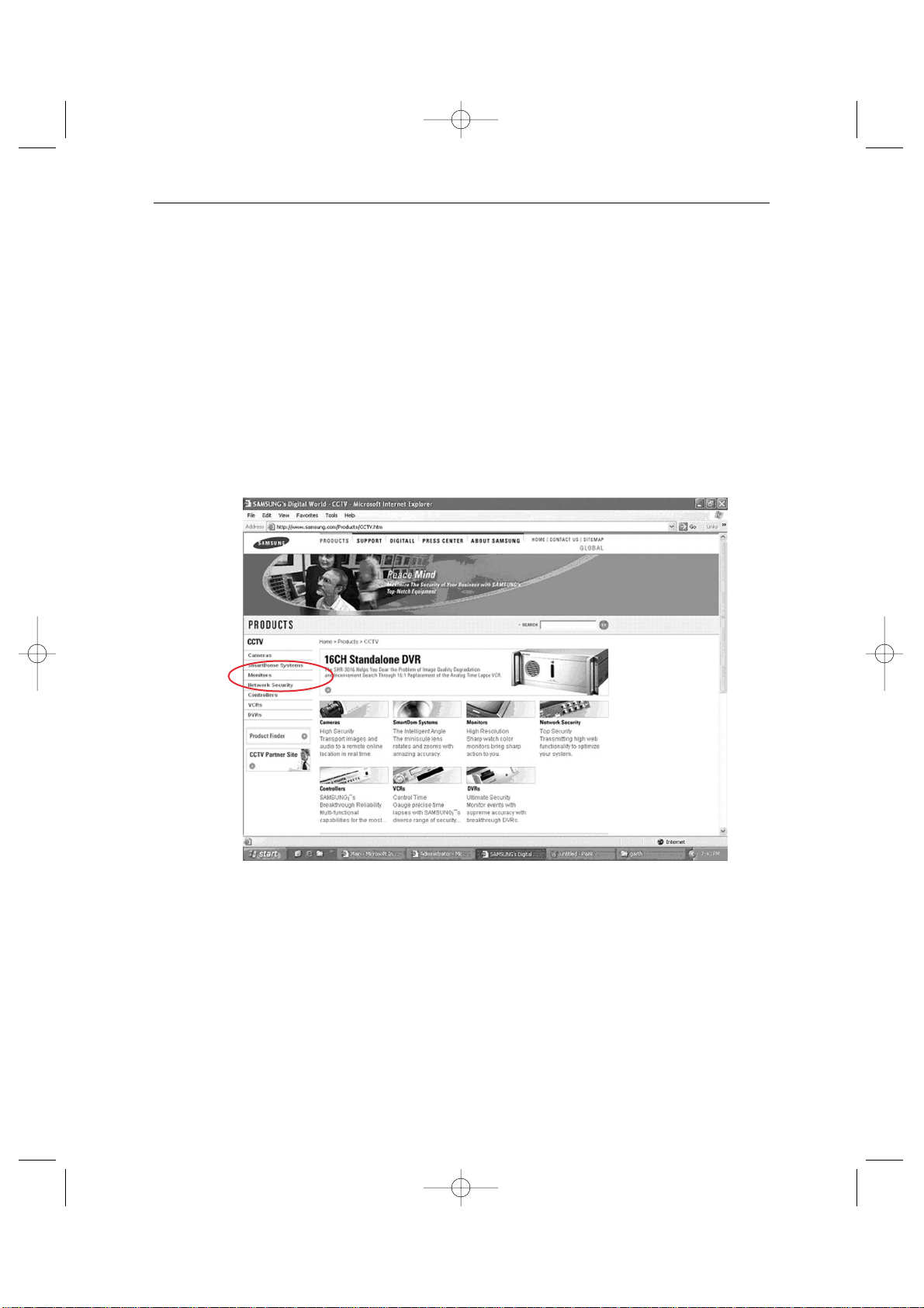
Eng-95
Appendix A) Software up data
The initial screen of Samsung Electronics’ web site is as follows.
1. http://www.securitysamsung.com
http://www.samsung.com/Products/CCTV.htm
2. Network Security in Homepage
3. Download the following items from SSC21WEB.
! Owner’s manual - SSC21WEB Owner’s manual
@ UP-GRADE S/W - kernel, RAM disk, System, Web
SSC21WEB-3 2004.8.25 6:48 PM Page 95
Page 96

Eng-96
Appendix B) IP Router Setup Guide
List of Routers compatible with SSC21WEB.
Refer to Router User’s Manual for the detailed router setup.
1. Total System Configuration
2. Local System Configuration
3. Step-by-Step Examples :
Linksys (Model : WRT54G)
Netgear (Model : WGR614v4)
D-Link (Model : DI-624+)
SMC (Model : 7004VBR)
CAUTION
Other routers may be incompatible with SSC21WEB.
SSC21WEB-3 2004.8.25 6:48 PM Page 96
Page 97
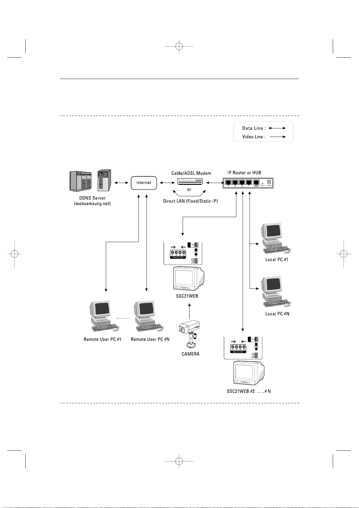
Eng-97
Total System Configuration
SSC21WEB-3 2004.8.25 6:48 PM Page 97
Page 98
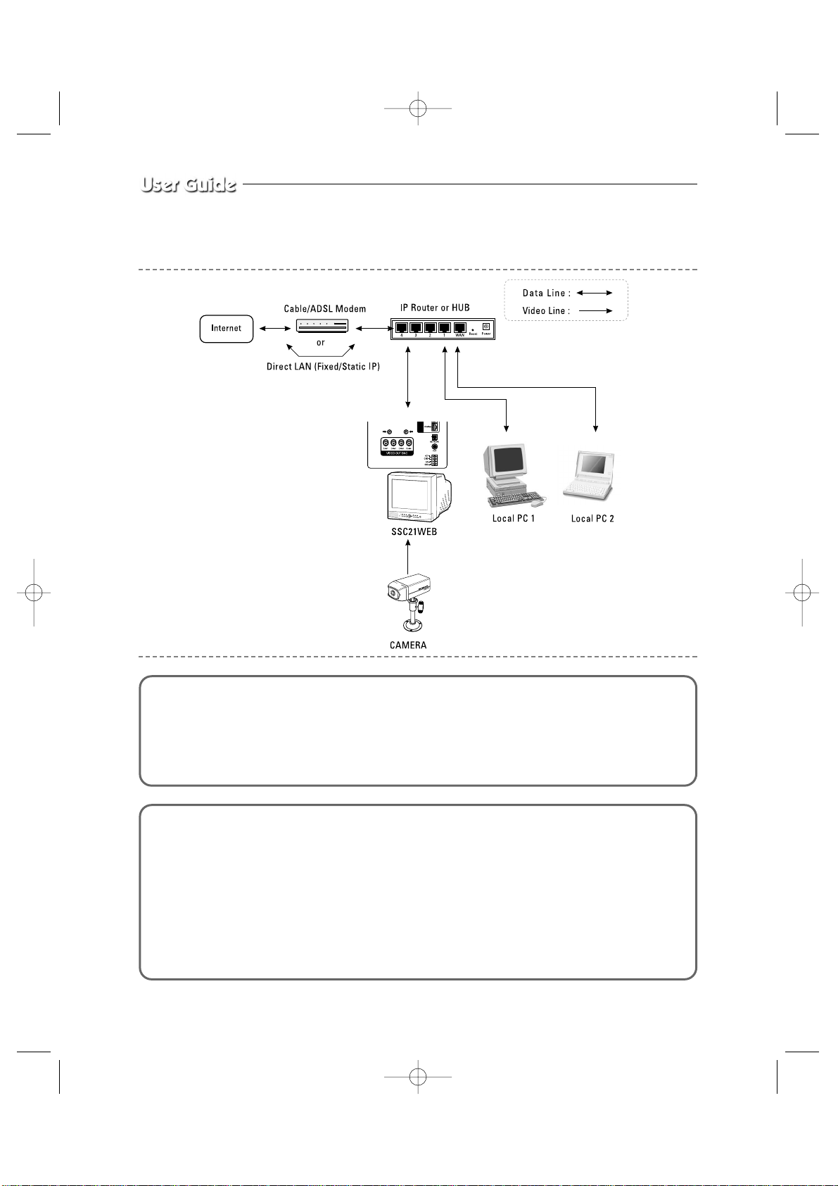
Eng-98
Local System Configuration
1.
Connect LAN cable of Cable/ADSL modem or Direct Fixed/Static IP LAN Line to WAN port of IP Router.
2. Connect LAN ports of IP Router(1~4 or 1~8) to Ethernet port SSC21WEB to be set up and to Ethernet port of
Local PC to use during setup.
3. Connect Video cable of Camera to SSC21WEB.
4. Turn on the SSC21WEB power.
Notice
If you have a Static (Fixed) IP line or Dynamic IP line (Cable Modem or ADSL Modem) with one IP address (whether its
dynamic or fixed), but have more than one internet device to use (such as a PC and a SSC21WEB or several SSC21WEB);
you must use an IP Router (different from a simple Network Hub); you must set up the Router to work with the SSC21WEB;
and you must use a network capable PC within the local Router network to do the setup.
If you are using an existing Router which is already set up, you may not need to redo the basic setup of the Router agian, but
it is highly recommended that you at least read all the instructions below and go through the steps.Whether you are using an
existing Router or a new Router, you must go through the Port Forwarding portion of the setup.
SSC21WEB-3 2004.8.25 6:48 PM Page 98
Page 99
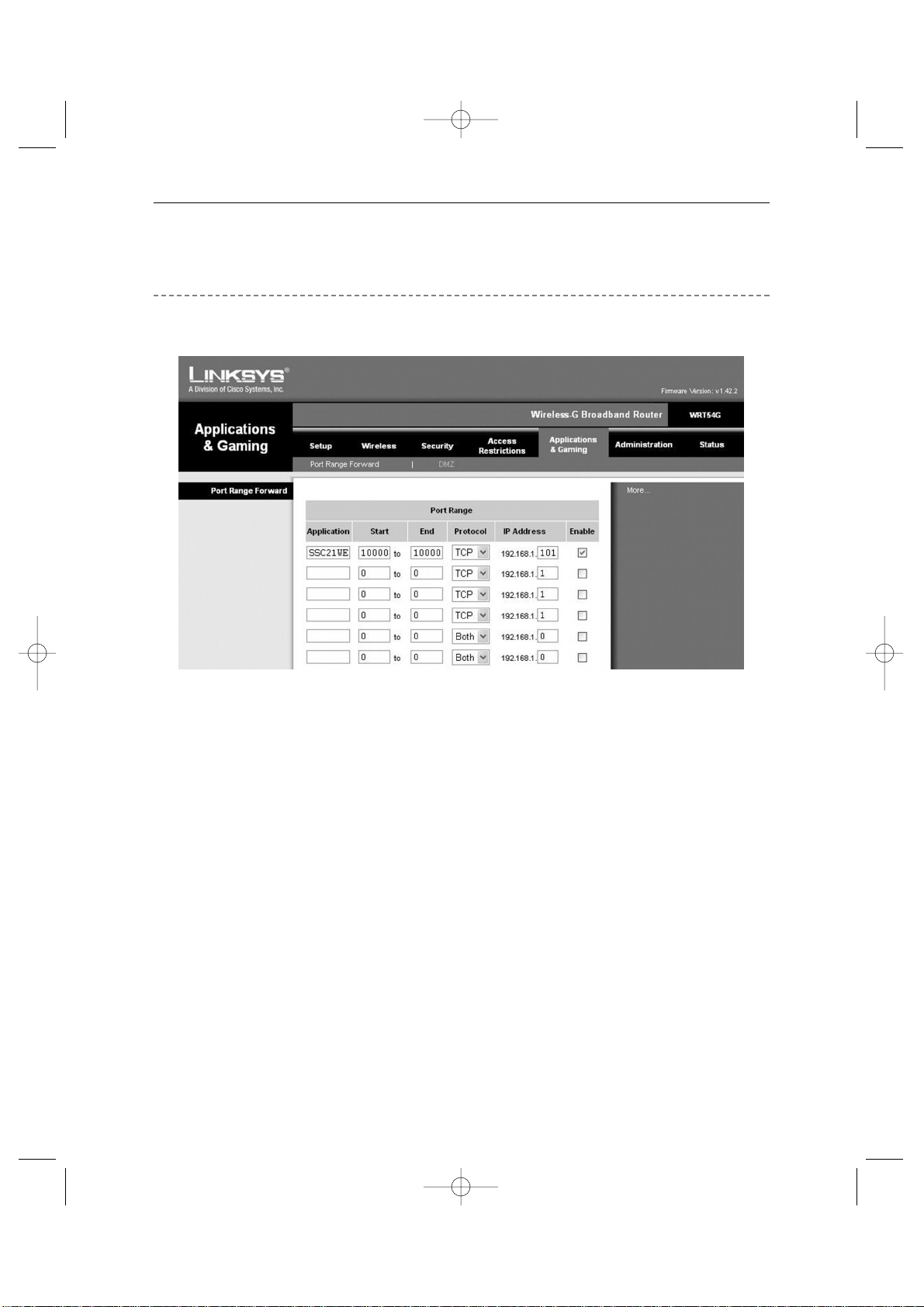
Eng-99
Step-by-Step Setup Example of IP Router
Linksys model WRT54G
1. Click the “Application and Gaming” tab.
2. Click “Port Range Forward”.
3. Port forwarding
Row #1 :
! Application : Set this to “HTTP”
@ Start and End : Set both to “From 10000 to 65535”
# Protocol : Select “TCP”
$ IP Address : SETUP MENU -> 7. NETWORK SETUP -> Check IP from network
status to apply it identically to Private IP after DHCP setup.
(Eng-32 Setup)
*
It is not in use by any other device connected to the IP Router including the Local PC.
% Enable : Leave this “checked”
4. Click “Save Settings”
5. Close browser window.
SSC21WEB-3 2004.8.25 6:48 PM Page 99
Page 100
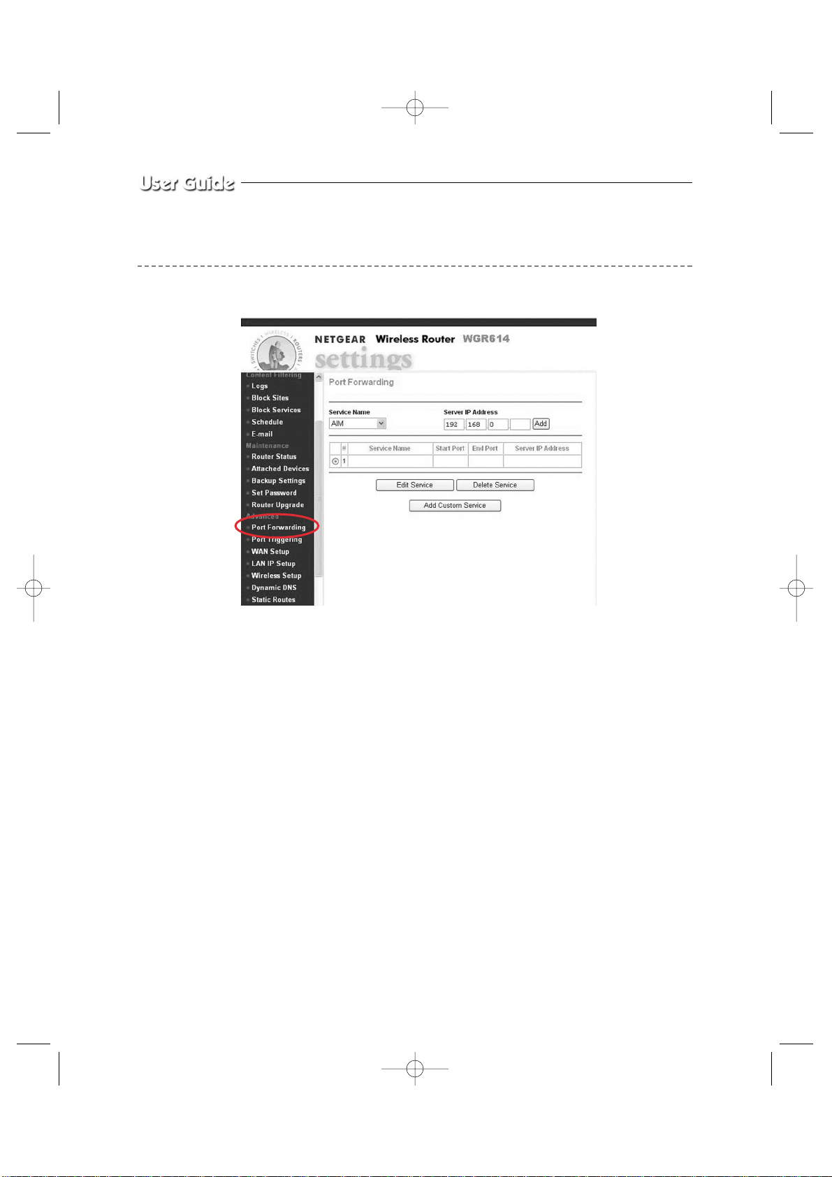
Eng-100
1. Click the “Router Status”
2. Click the WAN and LAN Port information.
Write down the WAN Port IP Subnet Mask number and the LAN Port IP Address number.
You will need it later when setting up the SSC21WEB.
3. Click “Advanced” and “Port Forwarding”
4. Port forwarding (HTTP)
! Click “Add Custom Service”
@ Service Name : Set this to “HTTP”
# Start Port and End Port : Set both to “From 10000 to 65535”
$ Server IP Address : SETUP MENU -> 7. NETWORK SETUP -> Check IP from
network status to apply it identically to Private IP after DHCP
setup. (Eng-32 Setup)
*
It is not in use by any other device connected to the IP Router including the Local PC.
% Make sure “Enable” is checked.
^ Click “Add”
5. Close browser window.
Step-by-Step Setup Example of IP Router
Netgear model WGR614v4
SSC21WEB 10000 10000 192.168.0.101
SSC21WEB-3 2004.8.26 10:1 AM Page 100
 Loading...