

Samsung SSA-P400, SSA-P401T, SSA-P401, SSA-P400T User Manual

SSA-P400
SSA-P400T
SSA-P401
SSA-P401T
Access Control Panel
user manual
imagine the possibilities
Thank you for purchasing this Samsung product.
To receive more complete service,
please visit our website.
www.samsungsecurity.com
safety information
CAUTION
RISK OF ELECTRIC SHOCK.
DO NOT OPEN
CAUTION: TO REDUCE THE RISK OF ELECTRIC SHOCK, DO NOT REMOVE COVER (OR BACK) NO USER SERVICEABLE
PARTS INSIDE. REFER SERVICING TO QUALIFIED SERVICE PERSONNEL.
This symbol indicates that dangerous voltage consisting a risk of electric shock is
present within this unit.
This exclamation point symbol is intended to alert the user to the presence of
important operating and maintenance (servicing) instructions in the literature
accompanying the appliance.
WARNING
To reduce the risk of fi re or electric shock, do not expose this appliance to rain or moisture.
•
WARNING
1.
Be sure to use only the standard adapter that is specifi ed in the specifi cation sheet.
Using any other adapter could cause fi re, electrical shock, or damage to the product.
2.
Incorrectly connecting the power supply or replacing battery may cause explosion, fi re, electric shock, or damage to
the product.
3.
Do not connect multiple controllers to a single adapter. Exceeding the capacity may cause abnormal heat generation or fi re.
4.
Securely plug the power cord into the power receptacle. Insecure connection may cause fi re.
5.
When installing the controller, fasten it securely and fi rmly. The fall of controller may cause personal injury.
6.
Do not place conductive objects (e.g. screwdrivers, coins, metal parts, etc.) or containers fi lled with water on top of the
controller. Doing so may cause personal injury due to fi re, electric shock, or falling objects.
7.
Do not install the unit in humid, dusty, or sooty locations. Doing so may cause fi re or electric shock.
8.
If any unusual smells or smoke come from the unit, stop using the product. In such case, immediately disconnect the
power source and contact the service center. Continued use in such a condition may cause fi re or electric shock.
9.
If this product fails to operate normally, contact the nearest service center. Never disassemble or modify this product in
any way. (SAMSUNG is not liable for problems caused by unauthorized modifi cations or attempted repair.)
10.
. When cleaning, do not spray water directly onto parts of the product. Doing so may cause fi re or electric shock.
CAUTION
1.
Do not drop objects on the product or apply strong blows to it. Keep away from a location subject to excessive
vibration or magnetic interference.
2.
Do not install in a location subject to high temperature (over 50°C), low temperature (below 0°C), or high humidity.
Doing so may cause fi re or electric shock.
3.
If you want to relocate the already installed product, be sure to turn off the power and then move or reinstall it.
4.
Remove the power plug from the outlet when there is a lighting storm. Neglecting to do so may cause fi re or damage
to the product.
2_ safety information

5.
Keep out of direct sunlight and heat radiation sources. It may cause fi re.
6.
Install it in a place with good ventilation.
7.
Avoid aiming the controller directly towards extremely bright objects such as sun.
8.
Apparatus shall not be exposed to dripping or splashing and no objects fi lled with liquids, such as vases, shall be
placed on the apparatus.
9.
The Mains plug is used as a disconnect device and shall stay readily operable at any time.
FCC Statement
This device complies with part 15 of the FCC Rules. Operation is subject to the following two conditions :
1)
This device may not cause harmful interference, and
2)
This device must accept any interference received including interference that may cause undesired operation.
SAFETY INFORMATION
Caution
This equipment has been tested and found to comply with the limits for a Class A digital device, pursuant to part
15 of FCC Rules. These limits are designed to provide reasonable protection against harmful interference when
the equipment is operated in a commercial environment.
This equipment generates, uses, and can radiate radio frequency energy and, if not installed and used in accordance with the instruction manual, may cause harmful interference to radio communications. Operation of this
equipment in a residential area is likely to cause harmful interference in which case the user will be required to
correct the interference at his own expense.
IMPORTANT SAFETY INSTRUCTIONS
Read these instructions.
1.
Keep these instructions.
2.
Heed all warnings.
3.
Follow all instructions.
4.
Do not use this apparatus near water.
5.
Clean only with dry cloth.
6.
Do not block any ventilation openings. Install in accordance with the manufacturer’s instructions.
7.
Do not install near any heat sources such as radiators, heat registers, or other apparatus (including amplifi ers) that
8.
produce heat.
Do not defeat the safety purpose of the polarized or grounding-type plug. A polarized plug has two blades with one
9.
wider than the other. A grounding type plug has two blades and a third grounding prong. The wide blade or the third
prong is provided for your safety. If the provided plug does not fi t into your outlet, consult an electrician for
replacement of the obsolete outlet.
Protect the power cord from being walked on or pinched particularly at plugs, convenience receptacles, and the
10.
point where they exit from the apparatus.
Only use attachments/accessories specifi ed by the manufacturer.
11.
Use only with cart, stand, tripod, bracket, or table specifi ed by the manufacturer, or sold with
12.
the apparatus.
Unplug this apparatus when a card is used. Use caution when moving the cart/ apparatus
13.
combination to avoid injury from tip-over.
Refer all servicing to qualifi ed service personnel. Servicing is required when the apparatus has been damaged in any
14.
way, such as powersupply cord or plug is damaged, liquid has been spilled or objects have fallen into the apparatus,
the apparatus has been exposed to rain or moisture, does not operate normally, or has been dropped.
English3

contents
PRODUCT INTRODUCTION
5
INSTALLATION AND EXTERNAL
CONNECTION
13
INITIALIZATION
22
TROUBLESHOOTING
24
5 Features
7 What’s included
12 Cable Selection
13 Connecting the termination resistor and
diode
14 Earth-grounding the communication cables
15 Power, Reader, and I/O Connection
18 Communication Line Connection
22 System Initialization
23 Board ID Setting
24 Troubleshooting
4_ contents
PRODUCT SPECIFICATIONS
26
26 Product Specifi cations

product introduction
FEATURES
State-of-the-art Access Controller
SSA-P400(T)/SSA-P401(T) is a state-of-the-art door access controller device that provides a high level security
system in an affordable price, meeting the needs in the security industry.
SSA-P400(T)/SSA-P401(T) can control access of 2-4 doors with simple manipulation and high level stability as well
as its affordable cost.
You can specify up to 1000 ~ 20,000(30,000/ 40,000/50,000) instances of card registration to your preference,
which you can delete or change as necessary. The built-in event memory can save up to 20,000 ~ 29,500(14,000/
8,000/3,000) instances of entires and alerts according to the number of registered cards.
You can connect a wide range of readers via the 4 reader ports, and operate the reader in either RF Card or RF
Card + PW mode.
15 independent input ports can be used to connect to various devices such as Exit Button, Door Contact Sensors,
PIR Sensors, and Window Breakage Sensors to reinforce security.
You can use the keypad (optional) to confi gure your settings with easy.
You can establish the independent or network connection via RS-232 or RS-422 communications. SSA-P400(T)/
SSA-P401(T) is equipped with a built-in TCP/IP module, which enables you to establish LAN communications. All
settings including card registration information, I/O settings, Real Time Clock, Time Schedules and all Event
Transaction Reports can be downloaded /uploaded from/to the host computer with software supporting a variety
of reporting formats.
Installed and managed inside the security zone for preventing the risk of damage, SSA-P400 (P401) can implement
a high level security access control system with multiple control options, best fi t for access control and time &
attendance management.
Standalone Operation
By connecting to 4 card readers, you can use this product to control the access of the maximum of 4 doors. This
controller determines to allow access by reading data from the card reader, and controls the open/close of the
door relay and enables you to change other output settings. Upon receipt of an incoming external input signal
(sensor or Exit button), it launches an output device such as the relay. This controller has an independent control
system, assuring a normal operation regardless of problems on any other systems and, not affecting them in the
reverse situation.
Anti-Pass Back
A door has two card readers installed: one for the entrance, and the other for the exit, so anyone who enters
should recognize his/her card on the reader at the entrance time before he can exit normally. If a person does not
go under the card recognition process and just follows another person’s way inside the door, the person is not
allowed to exit when he/she recognizes the access card on exit card reader, and the anti-pass-back error (APB
error) occurs which will be saved into the internal memory. And you can confi gure to output a certain signal through
a specifi c port if such an error occurs. (Make your setting using the Application program (controlled access, time
and attendance management, etc) – I/O Setup – APB Error) You can use Anti-Pass Back for controlling two doors
independently or in synchronization with each other.
PRODUCT INTRODUCTION
Computer-based Management
All records of authorized or unauthorized accesses and any external signal will be saved in the internal memory.
You can download such data onto your computer according to the specifi ed communications protocol. With the
downloaded data, you can store, process, and create a report based on your query (access and alert details, etc)
on the central computer.
Door Count Setup (2/3/4 doors)
As it is equipped with 4 card readers, you can use this product to control the access on a maximum of 4 doors.
For controlling 2 doors, install reader 1 and reader 2 on door 1 while installing reader 3 and reader 4 on door 2. For
controlling 3 doors, install reader 1 and reader 2 on door 1 while installing reader 3 on door 2, and reader 4 on
door 3. For controlling 4 doors, install one reader on each door, totalling 4.
English5

product introduction
Input Port Format Setup
15 input ports are provided by default. For these ports, you can specify if the format of the incoming signal is
blocked (NO) or connected (NC) in normal operation. This setting will make all ports operate same regardless of the
output status of the input device.
Time Scheduling
You can specify a time range during which a specifi c operation is performed. You can specify a specifi c time range
for a schedule code, which will be transferred to the applicable device. You can specify up to 5 different time
intervals for a day, ranging from Monday to Sunday including holidays. Each time schedule code can produce a
single different (or same) holiday code.
Door Open Alarm and Forced Door Open Alarm
The Door Open Alarm function notifi es the administrator that the door is still open if a door stays open after the
normal door open time and the standby time. (The output signal can be transferred via the output port, data on any
abnormal state will be stored in memory, which will be transferred upon request from the PC software. The Forced
Door Open Alarm function produces an alert when the door is forced to open and makes an alert again if the door
is still open after the timeout.
I/O Settings
This product is equipped with 15 input ports, 12 relay output ports, and 3 TTL output ports. You can use the
input ports to receive signals from the Exit button and the fi re sensor, and utilize this product to meet various
situations such as attaching the door lock to any of the 12 relays. You can also set the output time for these
output ports.
Holiday Setup
You can specify a holiday (legal holiday or bi-weekly holiday) excluding Sunday. You can specify up to 100 holidays
for a single holiday code. (Access can be permitted only for an allowable time range according to your time
schedule setting) A holiday code can be assigned to the time schedule code.
ARM/DISARM
In the condition where the ARM/DISARM code is specifi ed, if you enter the ARM/DISARM code and present the
card of the administrator (with master permissions) to the reader, the device triggers the alarm mode where you
can control the output signal in sync with the security system. In this mode, all connected readers will not take the
card input any further.
Duress Mode
This is used in a situation where you should open the door inevitably by a robber insisting to do so. Open the door
by entering the two-digit duress alarm password and pressing the
(or recognizing the card number), in the meantime this forcibly duress situation will be notifi ed to the PC application.
Two Men Operation Mode
This will allow access by visitors only under the control of the visitor guide.
Access will be permitted only if two cards are presented within a specifi ed time (10 seconds).
Dual Door Time Control
This allows you to specify two different settings for the entrance door control time according to the passers-by.
However, this can not be enabled with the ARM/DISARM function at the same time.
Data Maintenance
In the event of power failure, the controller retains all card information and the access/alert history (event data) until
it is damaged on the memory.
button before presenting the registered card
You can use the application program (SAMS Basic) to confi gure all theses settings to your preference.
J
6_ product introduction
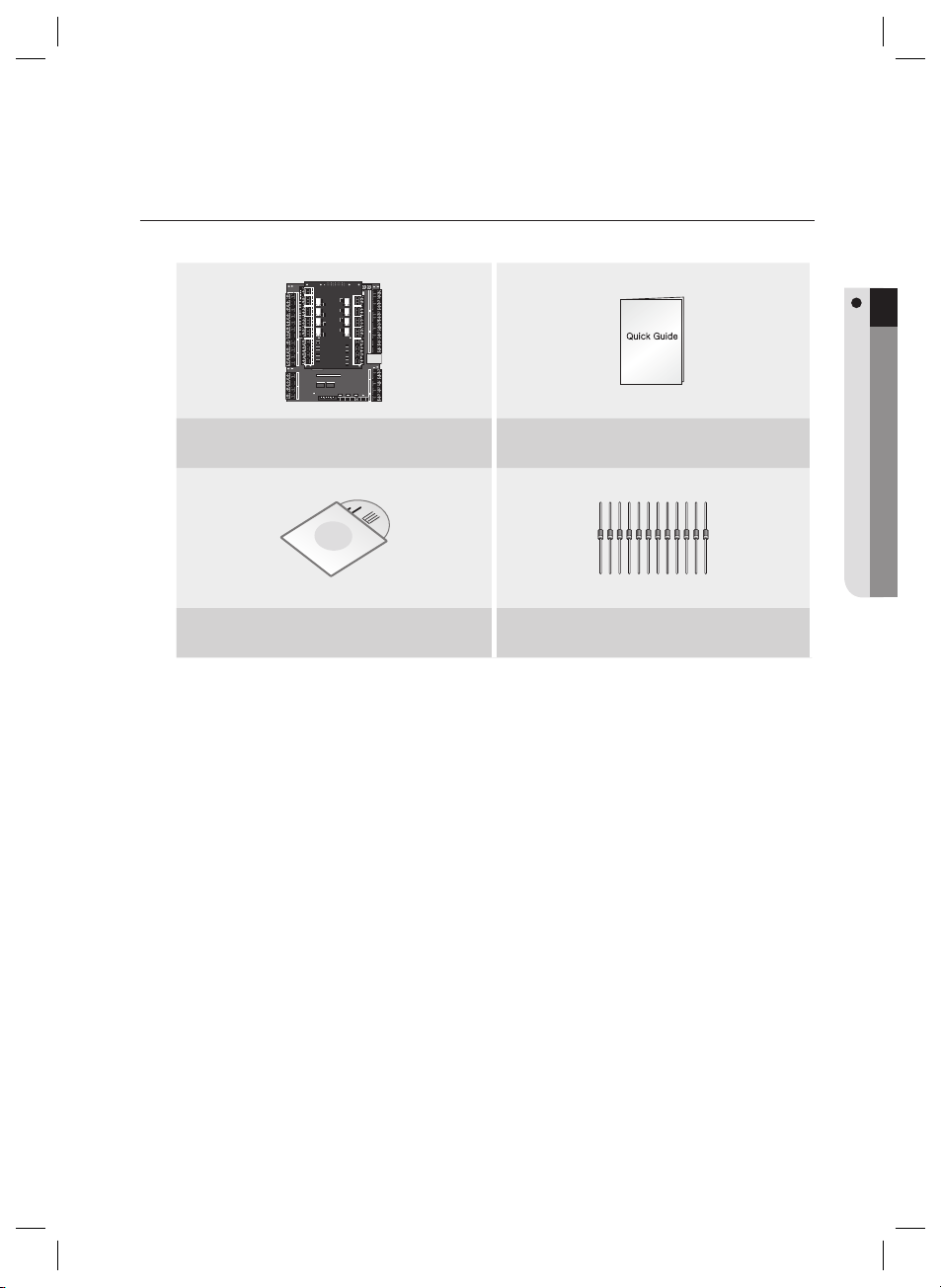
WHAT’S INCLUDED
Check if the following items are included in the product package.
Main Unit Quick Guide
PRODUCT INTRODUCTION
xGn
CD Manual
Diode (x12)
(UF4004, 1N4001~4007)
English7
product introduction
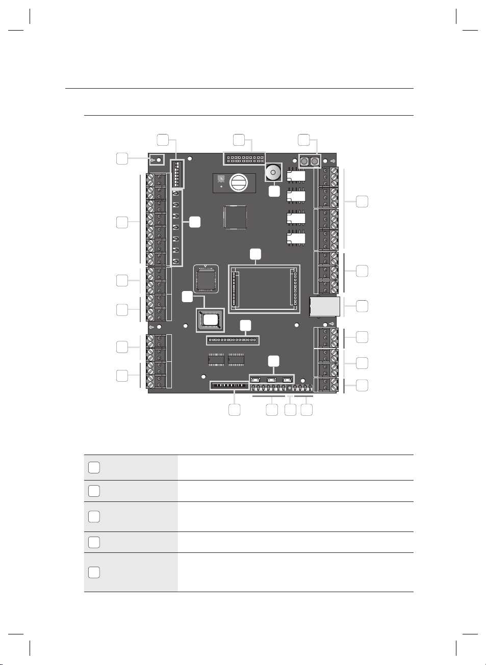
Main Board
1 2 3
24
25
4
23
21
20
19
18
Board ID Setup
1
Switch
I/O Board Connection
2
Port
System Initialization
3
Switch
Output (Relay #1 ~
4
Relay #4) Ports
Output (TTL #1 ~
TTL #3) Ports
5
Address Setup
Switch
22
16
5
17
6
15
7
10
8
9
11121314
The address number specifi ed by the address setup switch should match that of the
host computer as it is used for communications with the host computer.
Communication ports to connect to the I/O board, which include Input #8 through Input
#15 and Output #8 through Output #15.
Pressing both of the switches at the same time for about 2 seconds will sound
initialization ready beep. Releasing both switches will stop the beep, and restarts the
system after the initialization.
4 relay outputs (FORM-C(COM, NO, NC)) are provided. (DC12~18V, Max Current 2A)
3 TTL output ports are provided.
The voltage depends on the output occurrence, DC 0V for no output occurrence, and DC
5V for any output occurrence.
8_ product introduction
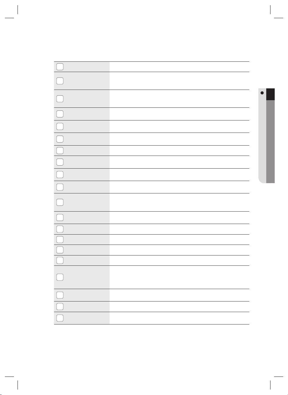
RJ-45
6
RS-232
Communication
7
Port
RS-422
Communication
8
Port
Power Connection
9
Port
LED Extension Port
10
TCP/IP Module LED
11
Indicator
Power LED Indicator
12
Output LED
13
Indicator
Keypad Connection
14
Port
LCD Connection
15
Port
TCP/IP Module
16
Connection Port
Firmware ROM
17
Reader #1 Port
18
Reader #2 Port
19
Reader #3 Port
20
Reader #4 Port
21
Input LED Indicator
22
Input Ports
23
(Input #1 ~ #7)
Fixing Hole
24
Buzzer
25
Connect the LAN cable for TCP/IP communications.
One RS-232 communication port is provided. Used to exclusively connect to a PC in a
local area.
One RS-422 communication port is provided.
You can establish up to 32 multi-drop communications.
DC +12V is used for the power source.
Port used to extend the power and communication indicators so that they can display
in an external device.
For TCP/IP module communications, the status of the TCP/IP module will be provided
additionally.
Power connection status indicator. It always stays ON while the power is applied.
Output status indicator for the output port. A fl ashing indicator denotes the occurrence
of any output.
Optional item.
Optional item.
The TCP/IP module is optional so it is not provided by default. Communication can be
established using the built-in TCP/IP module. Communication with the PC can be
established using the built-in TCP/IP module.
This must be replaced before the fi rmware update; you can check the current fi rmware
version.
The fi rst reader connection port.
The second reader connection port.
The third reader connection port.
The fourth reader connection port.
Indicates the status of the incoming signal to the input port. A fl ashing indicator denotes
the occurrence of any signal to the input port (NC-type input device). In the NO-type
connection, the LED indicator turns on if no sensor signal occurs while it turns off if any
signal occurs.
Input ports #1 ~ #7.
Fixing hole used to install the product through the bezel, using screws.
It will sound beeps on system initialization to the confi gured output depending on the
buzzer control settings.
PRODUCT INTRODUCTION
English9
 Loading...