

Samsung SS37 User Manual

SmartServer 370
User’s Guide

© Copyright SAMSUNG Electronics co., LTD . . All rights reserved.

Contents
Safety ............................v
Chapter 1. Introducing the SAMSUNG SmartServer 370 .........1
Related publications .......................2
Notices and statements used in this book ...............3
Features and specifications.....................4
What your server offers ......................5
Reliability, availability, and serviceability features .............7
Active Memory .........................8
Memory scrubbing and Memory ProteXion ..............8
Memory mirroring .......................8
IBM Director ..........................8
The UpdateXpress program ....................9
Server controls, LEDs, and power ..................10
Front view .........................10
Rear view..........................12
Server power features ......................14
Turning on the server .....................14
Turning off the server .....................15
Chapter 2. Configuring the server .................17
Using the Configuration/Setup Utility program .............18
Starting the Configuration/Setup Utility program ............18
Configuration/Setup Utility menu choices ..............18
Remote console redirection ...................23
Passwords .........................24
Using the ServerGuide Setup and Installation CD ............25
ServerGuide features .....................25
Setup and configuration overview .................26
System Partition .......................27
Typical operating-system installation ................27
Setting up or updating multiple servers ...............28
Installing your operating system without ServerGuide..........29
Configuring the Gigabit Ethernet controller...............29
Using the Extensible Firmware Interface boot manager ..........29
Using the integrated system management firmware update utility program . . . 30
Using the LSI Logic Configuration Utility program ............31
Starting the LSI Logic Configuration Utility program ..........31
Formatting a SCSI hard disk drive.................31
Creating a mirrored pair of SCSI hard disk drives ...........32
Setting up the Remote Supervisor Adapter...............32
Remote Supervisor Adapter features ................32
Setup requirements ......................32
Using the documentation ....................33
Cabling and configuring the Remote Supervisor Adapter.........33
Using the ASM interconnect network ................43
Using the PXE boot agent utility program ...............50
Starting the PXE boot agent utility program .............50
PXE boot agent utility menu choices ................50
Using ServeRAID Manager ....................51
Configuring the controller ....................51
Viewing the configuration ....................56
Getting assistance ......................57
© Copyright SAMSUNG Electronics co., LTD. All rights reserved. iii

Configuring scalable partitions ...................58
Creating a scalable partition ...................59
Deleting a scalable partition ...................60
iv User’s Guide
Safety
Before installing this product, read the Safety Information.
Antes de instalar este produto, leia as Informações de Segurança.
Pred instalací tohoto produktu si prectete prírucku bezpecnostních instrukcí.
Læs sikkerhedsforskrifterne, før du installerer dette produkt.
Lees voordat u dit product installeert eerst de veiligheidsvoorschriften.
Ennen kuin asennat tämän tuotteen, lue turvaohjeet kohdasta Safety Information.
Avant d’installer ce produit, lisez les consignes de sécurité.
Vor der Installation dieses Produkts die Sicherheitshinweise lesen.
Prima di installare questo prodotto, leggere le Informazioni sulla Sicurezza.
Les sikkerhetsinformasjonen (Safety Information) før du installerer dette produktet.
Antes de instalar este produto, leia as Informações sobre Segurança.
v
Antes de instalar este producto, lea la información de seguridad.
Läs säkerhetsinformationen innan du installerar den här produkten.
Statement 1:
DANGER
Electrical current from power, telephone, and communication cables is
hazardous.
To avoid a shock hazard:
v Do not connect or disconnect any cables or perform installation,
maintenance, or reconfiguration of this product during an electrical
storm.
v Connect all power cords to a properly wired and grounded electrical
outlet.
v Connect to properly wired outlets any equipment that will be attached to
this product.
v When possible, use one hand only to connect or disconnect signal
cables.
v Never turn on any equipment when there is evidence of fire, water, or
structural damage.
v Disconnect the attached power cords, telecommunications systems,
networks, and modems before you open the device covers, unless
instructed otherwise in the installation and configuration procedures.
v Connect and disconnect cables as described in the following table when
installing, moving, or opening covers on this product or attached
devices.
vi User’s Guide
To Connect: To Disconnect:
1. Turn everything OFF.
2. First, attach all cables to devices.
3. Attach signal cables to connectors.
4. Attach power cords to outlet.
5. Turn device ON.
1. Turn everything OFF.
2. First, remove power cords from outlet.
3. Remove signal cables from connectors.
4. Remove all cables from devices.
Statement 2:
CAUTION:
When replacing the lithium battery, use an equivalent type battery recommended
by the manufacturer. If your system hasa module containing a lithium battery,
replace it only with the same module type made by the same manufacturer.
The battery contains lithium and can explode if not properly used, handled,
or disposed of.
Do not:
v Throw or immerse into water
v Heat to more than 100°C (212°F)
v Repair or disassemble
Dispose of the battery as required by local ordinances or regulations.
Statement 3:
CAUTION:
When laser products (such as CD-ROMs, DVD drives, fiber optic devices, or
transmitters) are installed, note the following:
v Do not remove the covers. Removing the covers of the laser product could
result in exposure to hazardous laser radiation. There are no serviceable
parts inside the device.
v Use of controls or adjustments or performance of procedures other than
those specified herein might result in hazardous radiation exposure.
DANGER
Some laser products contain an embedded Class 3A or Class 3B laser
diode. Note the following.
Laser radiation when open. Do not stare into the beam, do not view directly
with optical instruments, and avoid direct exposure to the beam.
Safety vii
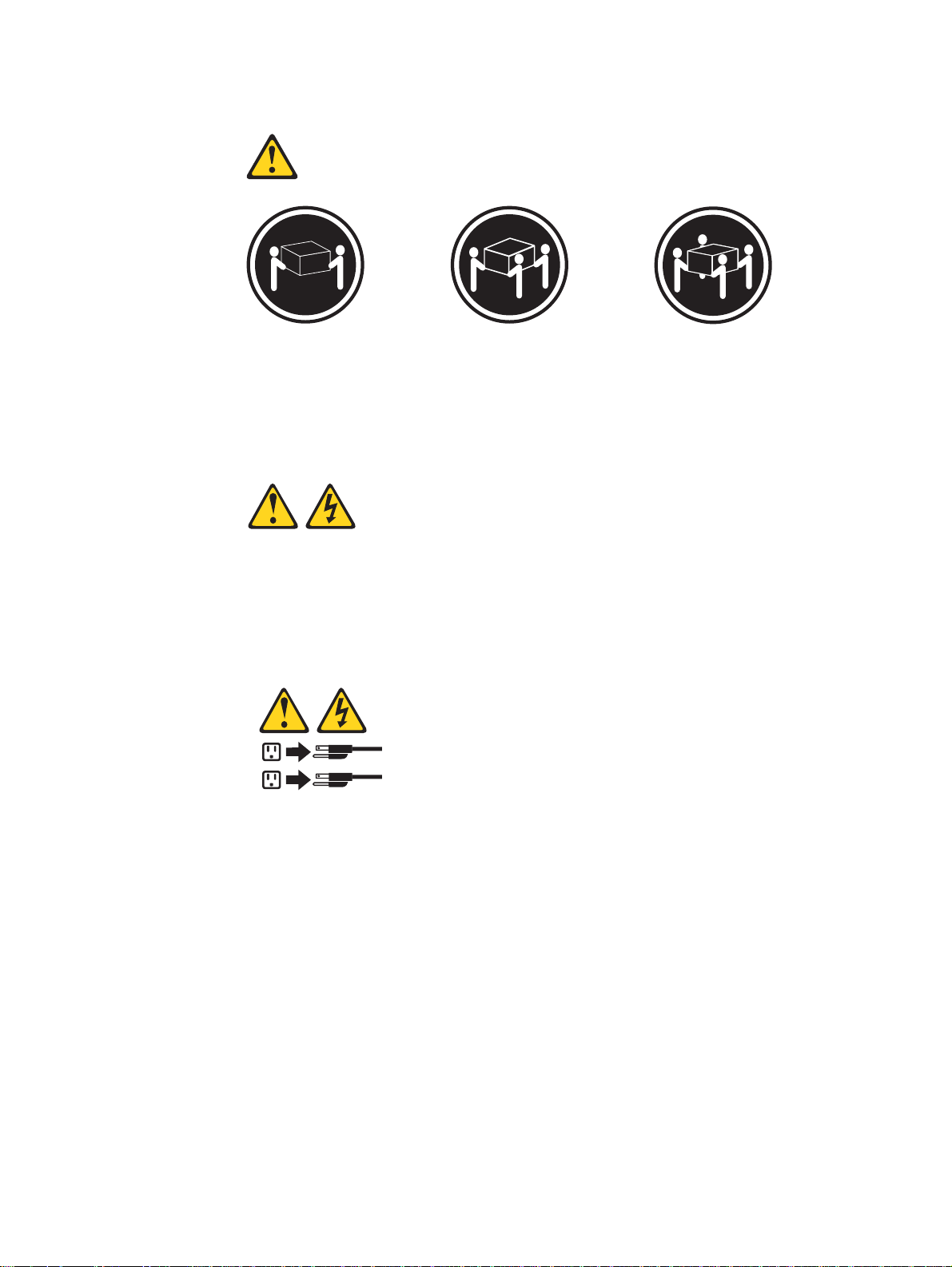
Statement 4:
≥ 18 kg (39.7 lb) ≥ 32 kg (70.5 lb) ≥ 55 kg (121.2 lb)
CAUTION:
Use safe practices when lifting.
Statement 5:
CAUTION:
The power control button on the device and the power switch on the power
supply do not turn off the electrical current supplied to the device. The device
also might have more than one power cord. To remove all electrical current
from the device, ensure that all power cords are disconnected from the power
source.
viii User’s Guide
2
1
Statement 8:
CAUTION:
Never remove the cover on a power supply or any part that has the following
label attached.
Hazardous voltage, current, and energy levels are present inside any
component that has this label attached. There are no serviceable parts inside
these components. If you suspect a problem with one of these parts, contact
a service technician.
Statement 10:
CAUTION:
Do not place any object weighing more than 82 kg (180 lb) on top of
rack-mounted devices.
>82 kg (180 lb)
Statement 13:
DANGER
Overloading a branch circuit is potentially a fire hazard and a shock hazard
under certain conditions. To avoid these hazards, ensure that your system
electrical requirements do not exceed branch circuit protection
requirements. Refer to the information that is provided with your device for
electrical specifications.
Safety ix

WARNING: Handling the cord on this product or cords associated with accessories
sold with this product, will expose you to lead, a chemical known to the State of
California to cause cancer, and birth defects or other reproductive harm. Wash
hands after handling.
ADVERTENCIA: El contacto con el cable de este producto o con cables de
accesorios que se venden junto con este producto, pueden exponerle al plomo, un
elemento químico que en el estado de California de los Estados Unidos está
considerado como un causante de cancer y de defectos congénitos, además de
otros riesgos reproductivos. Lávese las manos después de usar el producto.
x User’s Guide

Chapter 1. Introducing the SAMSUNG SmartServer 370
Your SAMSUNG SmartServer 370 server is a 4-U-high 1rack model server for
high-volume network transaction processing. This high-performance server, based
on Enterprise X-Architecture
environments that require superior microprocessor performance, efficient memory
management, flexibility, and reliable data storage.
The SmartServer 370 comes with a limited warranty. You can obtain up-to-date
information about your SmartServer 370 model and other SAMSUNG server
products at http://www.sec.co.kr/server.
Your SmartServer 370 contains several Enterprise X-Architecture technologies,
that help increase performance and reliability. The Enterprise X-Architecture
technologies provided in your server model include the most recent advancements
in X-Architecture features. For more information see “What your server offers"
on page 5 and “Reliability, availability, and serviceability features” on page 7.
The machine type and serial number are located on the ID label located on the left
side of the bezel just above the hard disk drives. You will need these numbers
when you register your server with SAMSUNG.
™
technologies, is ideally suited for networking
1. Racks are marked in vertical increments of 1.75 inches each. Each increment is referred to as a unit, or ″U.″ A 1-U-high device is
1.75 inches tall.
1

Related publications
This User’s Guide provides general information about your server, including
information about features, how to configure the server, and how to get help. In
addition to this User’s Guide, the following documentation comes with your server:
v Installation Guide
This printed publication contains instructions for setting up your server and basic
instructions for installing some options.
v Option Installation Guide
This publication is in PDF on the Documentation CD. It contains
detailed instructions for installing, removing, and connecting optional devices that
your server supports.
v Safety Information
This publication is in PDF on the Documentation CD. It contains
translated caution and danger statements. Each caution and danger statement
that appears in the documentation has a number that you can use to locate the
corresponding statement in your language in the Safety Information book.
v Rack Installation Instructions
This printed publication contains instructions for installing your server in a rack
cabinet.
v Hardware Maintenance Manual and Troubleshooting Guide
This publication is in PDF on the Documentation CD. It contains
information to help you solve problems yourself, and it contains information for
service technicians.
Depending on your server model, additional publications might be included on the
Documentation CD.
Your server might have features that are not described in the documentation that
you received with the server. The documentation might be updated occasionally to
include information about those features, or technical updates might be available to
provide additional information that is not included in your server documentation.
These updates are available from the SAMSUNG Web site. Complete the following
steps to check for updated documentation and technical updates:
1. Go to http://www.sec.co.kr/server.
2. In the Family field, select SmartServer 370.
3. Click Display documents.
2 User’s Guide

Notices and statements used in this book
The caution and danger statements used in this book also appear in the multilingual
Safety Information book provided on the Documentation CD. Each
caution and danger statement is numbered for easy reference to the corresponding
statement in the safety book.
The notice and statement definitions are as follows:
v Note: These notices provide important tips, guidance, or advice.
v Important: These notices provide information or advice that might help you avoid
inconvenient or problem situations.
v Attention: These notices indicate possible damage to programs, devices, or
data. An attention notice is placed just before the instruction or situation in which
damage could occur.
v Caution: These statements indicate situations that can be potentially hazardous
to you. A caution statement is placed just before the description of a potentially
hazardous procedure step or situation.
v Danger: These statements indicate situations that can be potentially lethal or
extremely hazardous to you. A danger statement is placed just before the
description of a potentially lethal or extremely hazardous procedure step or
situation.
Chapter 1. Introducing the SmartServer 370 3

Features and specifications
The following information is a summary of the features and specifications of your
server.
Microprocessor:
v Supports the following microprocessors:
– Up to 8 Intel Xeon MP microprocessors (16
in a 16-way configuration)
– Up to 4 Intel Xeon DP microprocessors
Note: Use the Information in BIOS to
determine the type and speed of the
microprocessors installed in your server.
v IBM XA-32
I/O, system cache, and remote I/O controllers
Memory:
v Minimum: 2 GB
v Maximum: 64 GB
v Type: 2-way interleaved PC1600, DDR
SDRAM, registered DIMMs only
v Supports 512 MB, 1GB and 2 GB dual inline
memory modules (DIMMs)
v XceL4
MB per SMP Expansion Module)
Drives:
v Diskette: 1.44 MB
v DVD-ROM
v Supports up to two internal Ultra320 SCSI
hard disk drives
Active
Six 64-bit Active PCI-X expansion slots:
v Two 66 MHz PCI-X slots
v Two 100 MHZ PCI-X slots
v Two 133 MHZ PCI-X slots
v Additional PCI-X slots available in an optional
remote I/O expansion enclosure
Cooling:
Four hot-swap fans:
v Two 150 mm x 51 mm redundant fans
v Two 150 mm x 38 mm fans
™
chip set with integrated memory,
™
Server Accelerator Cache (up to 64
™
PCI-X expansion slots:
Power supply:
Two hot-swap power supplies (550 watts at 110
V ac or 1050 watts at 220 V ac)
Video:
v ATI Rage XL video on system board
v PCI bus interface
v Compatible with SVGA
v 8 MB SDRAM video memory at 125 MHz
Size (4 U):
v Height: 17.8 cm (7 inches, 4 U)
v Depth: 69.85 cm (27.5 inches)
v Width: 48.3 cm (19 inches)
v Maximum weight: 50 kg (110 lb) depending
on your configuration
Integrated functions:
v Broadcom 5704 Dual Gigabit 10/100/1000
Ethernet controller
v Light Path Diagnostics
v LSI Logic 1030 Dual Ultra320 SCSI
controller
v Remote Supervisor Adapter (service
processor)
– ASM interconnect (peer-to-peer) port
– Ethernet port
– Management port
v IDE controller
v RXE Management Port
v Three USB connectors
v Keyboard connector
v SCSI connector
v Mouse connector
v Symmetrical multiprocessing (SMP)
Expansion Ports (up to six ports depending
on your configuration)
v Two remote I/O expansion enclosure (RXE)
Expansion Ports
Acoustical noise emissions:
v Sound power, idling: 6.5 bel maximum
v Sound power, operating: 6.5 bel maximum
™
feature
Environment:
v Air temperature:
– Server on: 10° to 35°C (50.0° to 95.0°F).
Altitude: 0 to 914 m (2998.7 ft).
– Server on: 10° to 32° C (50.0° to 89.6° F).
Altitude: 914 m (2998.7 ft) to 2133 m
(6998.0 ft).
– Server off: -40° to 60° C
(-104° to 140° F). Maximum altitude: 2133 m
(6998.0 ft).
v Humidity:
– Server on: 8% to 80%
– Server off: 5% to 100%
Heat output:
Approximate heat output in British thermal units
(Btu) per hour:
v Minimum configuration: 855 Btu (250 watts)
v Maximum configuration: 2726 Btu (800 watts)
Electrical input:
v Sine-wave input (50 or 60 Hz) required
v Input voltage low range:
– Minimum: 100 V ac
– Maximum: 127 V ac
v Input voltage high range:
– Minimum: 200 V ac
– Maximum: 240 V ac
v Input kilovolt-amperes (kVA) approximately:
– Minimum: 0.250 kVA
– Maximum: 0.800 kVA
Notes:
1. Power consumption and heat output vary
depending on the number and type of optional
features installed and the power-management
optional features in use.
2. These levels were measured in controlled
acoustical environments according to the
procedures specified by the American National
Standards Institute (ANSI) S12.10 and ISO
7779 and are reported in accordance with ISO
9296. Actual sound-pressure levels in a given
location might exceed the average values
stated because of room reflections and other
nearby noise sources. The declared
sound-power levels indicate an upper limit,
below which a large number of computers will
operate.
4 User’s Guide

What your server offers
Your server uses the following features and technologies:
v Accelerated Graphics Port (AGP) adapter
Your server comes with an integrated AGP graphics adapter. This
high-performance adapter supports high resolutions and includes many
performance-enhancing features for your operating-system environment.
v IBM Director
IBM Director is a workgroup-hardware-management tool that you can use
to centrally manage SmartServer.. For more information about IBM Director,
see the IBM Director User’s Guide on the IBM Director CD.
v Enterprise X-Architecture technology
X-Architecture technology combines proven, innovative IBM designs to
make your Intel-processor-based server powerful, scalable, and reliable.
For more information, go to http://www.sec.co.kr/server.
– Active
The Active Memory feature improves the reliability of memory through memory
mirroring, memory scrubbing, and the Memory ProteXion
information, see “Active Memory” on page 8.
– Large system-memory capacity
The memory bus supports up to 64 GB of system memory. The memory
controller supports error correcting code (ECC) for up to 32 industry-standard
PC1600, 133 megahertz (MHz), 3.3 V, 168-pin, registered, double-data-rate
(DDR), synchronous dynamic random access memory (SDRAM) dual inline
memory modules (DIMMs).
– Memory ProteXion
The Memory ProteXion feature provides the equivalent of a hot-spare drive in
a RAID array. It is based in the memory controller, and it enables the server to
sense when a chip on a DIMM has failed and to route the data around the
failed chip.
– XceL4
The XceL4 Server Accelerator Cache provides up to 64MB of external Level-4
cache per SMP Expansion Module, which increases memory bandwidth and
reduces access time through PCI-X, Ethernet, SCSI, and Fibre Channel
interfaces.
v ServerGuide
The ServerGuide Setup and Installation CD that comes with your server provides
programs to help you set up your server and install the operating system. The
ServerGuide program detects installed hardware options and provides the correct
configuration programs and device drivers. For more information about the
ServerGuide Setup and Installation CD, see “Using the ServerGuide Setup and
Installation CD” on page 25.
™
Memory
™
Server Accelerator Cache
™
Setup and Installation CD
™
feature. For more
Note: If your server model came with an operating system, such as Microsoft
Windows®2000 Datacenter Server or VMware ESX server, see the
software documentation provided with your software for configuration
information.
Chapter 1. Introducing the SmartServer 370 5
®

v Integrated network support
Your server comes with an integrated Broadcom 5704 Dual Gigabit Ethernet
controller, which supports connection to a 10-Mbps, 100-Mbps, or 1000-Mbps
network. For more information, see “Configuring the Gigabit Ethernet controller”
on page 29.
v Large data-storage capacity and hot-swap capability
Your server supports up to two 25.4-mm (1-inch) slim-high, 3.5-inch hot-swap
hard disk drives in the hot-swap bays. With the hot-swap feature, you can add,
remove, or replace hard disk drives without turning off the server.
v Light Path Diagnostics feature
The Light Path Diagnostics feature provides LEDs to help you diagnose
problems. For more information, see the section about the Light Path Diagnostics
feature in the Installation Guide.
v Redundant connection
The intergrated dual Giagabit Ethernet ports provide a failover capability. If a
problem occurs with the primary Ethernet connection, all Ethernet traffic
associated with the primary connection is automatically switched to the
secondary connection. If the appropriate device drivers are installed, this
switching occurs without data loss and without user intervention.
v Redundant cooling and power capabilities
The redundant cooling of the fans in your server enable continued operation if
one of the fans fails. Your server comes with two 550-watt hot-swap power
supplies, which provide redundant power for many server configurations. If the
average load on your server is less than 550 watts and a problem occurs with
one of the power supplies, the other power supply can meet the power
requirements.
v Scalable partitions
Your server is scalable and can be connected to another server so that you can
share resources between servers.
™
v ServeRAID
support
Your server supports ServeRAID adapters to create redundant array of
independent disks (RAID) configurations.
v Symmetric multiprocessing (SMP)
Your server supports up to eight Intel Xeon microprocessors (sixteen in a 16-way
configuration). The server comes with two microprocessor. You can install
additional microprocessors to enhance performance.
v Systems-management capabilities
The server comes with a Remote Supervisor Adapter installed. The adapter and
the systems-management software that comes with your server enable you to
manage the functions of the server locally and remotely. The Remote Supervisor
Adapter also provides system monitoring, event recording, and dial-out alert
capability.
6 User’s Guide

Reliability, availability, and serviceability features
Three important computer design features are reliability, availability, and
serviceability (RAS). The RAS features help to ensure the integrity of the data that
is stored in your server, the availability of the computer when you need it, and the
ease with which you can diagnose and repair problems.
Your server has the following RAS features:
v Active Memory
v Active PCI-X (hot-plug) adapter slots
v Advanced Configuration and Power Interface (ACPI)
v Advanced Desktop Management Interface (DMI) features
v Advanced memory ECC, including Memory ProteXion, and multiple Chipkill
capability
v Automatic error retry or recovery
v Auto-restart initial program load (IPL) power supply
v Automatic server restart
v Built-in, menu-driven Configuration/Setup Utility and diagnostic programs
v Built-in monitoring for fan, power, temperature, voltage, and power-supply
redundancy
v Customer-upgradable basic input/output system (BIOS) code
v Diagnostic support of Ethernet controllers
v Error codes and messages
v Error correcting code (ECC) protection on the L3 and XceL4 cache
v Failover Ethernet support
v Front-side buses (FSBs) parity protected
v Hot-add memory
v Hot-replace memory
v Hot-swap cooling with fan speed-sensing capability
v Hot-swap hard disk drives
v Light Path Diagnostics
v Memory mirroring
v Microsoft Windows Server family failover support
v Monitoring support for temperature, voltage, and fan speed
v Parity checking on the SCSI buses
v Power-on self-test (POST)
v Processor serial number access
v Read-only memory (ROM) checksums
v Redundant hot-swap
– Cooling fans with speed-sensing capability
– Power supplies
v Remote Supervisor Adapter to enable remote server management
v SDRAM with serial presence detect (SPD) and vital product data (VPD)
v Standard cable presence detection
v Standby voltage for systems-management features and monitoring
v System error logging
v Vital product data (VPD) (includes information stored in nonvolatile memory for
easier remote viewing)
v Wake on LAN
®
capability
™
Chapter 1. Introducing the SmartServer 370 7

Active Memory
Active™ Memory is an feature that improves the reliability of memory through
memory mirroring, memory scrubbing, and the Memory ProteXion™ feature.
Memory scrubbing and Memory ProteXion
Memory scrubbing tests the memory at regular intervals to detect and report
potential memory errors before they can cause server outages.
If a detected error is recoverable, the Memory ProteXion feature corrects the error
and rewrites the data to another memory location on the same DIMM. The error is
logged in the error log so that you can determine whether preventive maintenance
is necessary.
If there are not sufficient undamaged memory locations that the data can be
rewritten to, the error is unrecoverable. Other conditions can also cause
unrecoverable errors. If a detected error is unrecoverable, LEDs on the Light Path
Diagnostics panel are lit to indicate the failing DIMM.
You do not have to enable memory mirroring to use memory scrubbing and the
Memory ProteXion feature.
Memory mirroring
Memory mirroring stores data in memory port 1 and memory port 2 simultaneously.
To support memory mirroring, you must install identical dual inline memory modules
(DIMMs) in memory port 1 and memory port 2. For more information, see the
section about installing memory modules in the Option Installation Guide on the
Documentation CD.
IBM Director
To enable memory mirroring through the Configuration/Setup Utility program, select
Advanced Setup from the main menu, and select Memory Settings. For more
information about using the Configuration/Setup Utility program, see Chapter 2,
“Configuring the server”, on page 17.
Note: To use the hot-add memory feature memory mirroring must be disabled in
the BIOS code.
With IBM Director, a network administrator can:
v View the hardware configuration of remote systems, in detail
v Monitor the usage and performance of critical components, such as
microprocessors, disks, and memory
v Centrally manage individual or large groups of SAMSUNG and non-SAMSUNG
Intel-based servers, desktop computers, workstations, and mobile computers on
a variety of platforms
IBM Director provides a comprehensive entry-level workgroup hardware manager.
Key features include:
v Advanced self-management capabilities for maximum system availability
v Multiple operating-system platform support, including Windows 2000, Windows
XP Professional, Novell NetWare, Linux, and Caldera OpenUNIX
8 User’s Guide

v Support for SAMSUNG and non-SAMSUNG servers, desktop computers,
workstations, and mobile computers
v Support for systems-management industry standards
v Integration into leading workgroup and enterprise systems-management
environments
v Ease of use, training, and setup
IBM Director also provides an extensible platform that supports advanced server
tools that are designed to reduce the total cost of managing and supporting
networked systems. By deploying IBM Director, you can achieve reductions in
ownership costs through:
v Reduced downtime
v Increased productivity of IT personnel and users
v Reduced service and support costs
For more information about IBM Director, see the IBM Director CD that comes with
your server, the IBM Director publications on the CD.
Systems Management - IBM Director Package
http://www.sec.co.kr/server
This Web page includes links to software downloads and publications for
the latest release of IBM Director.
The UpdateXpress program
The UpdateXpress program is available for most SmartServer and server options.
It detects supported and installed device drivers and firmware in your server and
installs available updates. You can download the UpdateXpress program from
the Web at no additional cost, or you can purchase it on a CD. To download
the program or purchase the CD, go to http://www.sec.co.kr/server/.
Chapter 1. Introducing the SmartServer 370 9
Server controls, LEDs, and power
The following section identifies the controls and indicators on the front and rear of
your server.
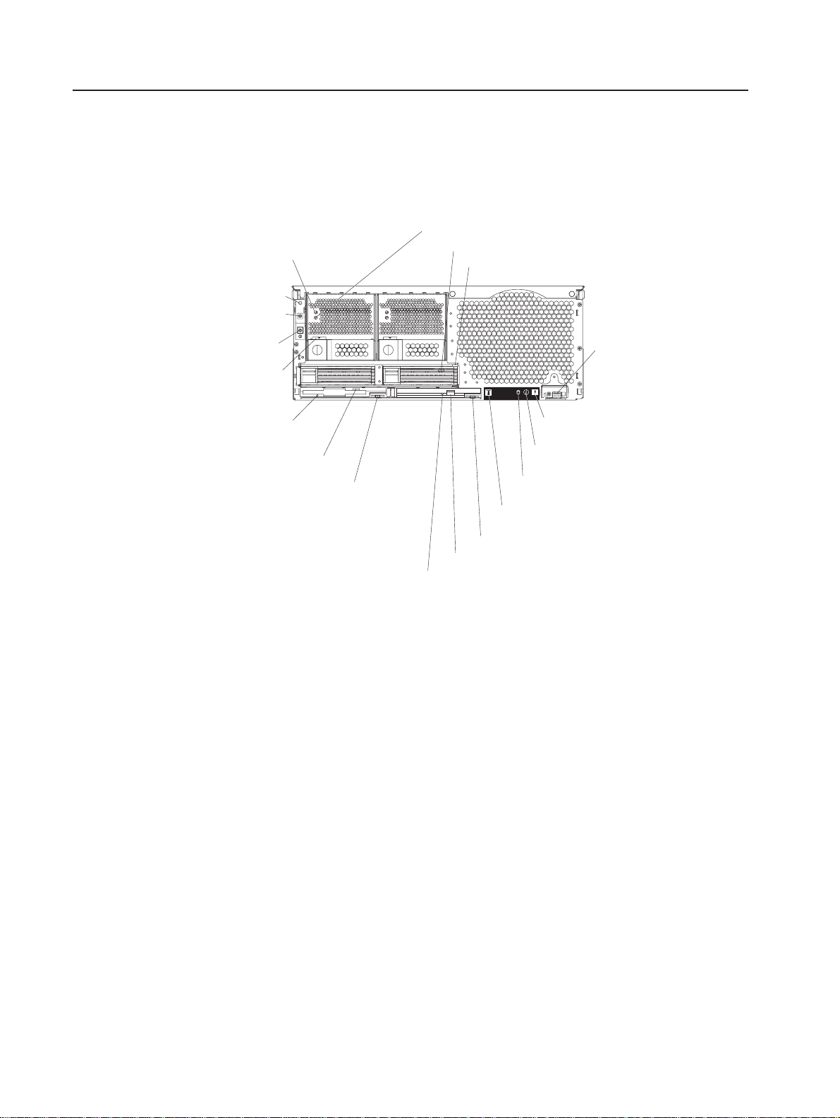
Front view
AC power LED
Power-on LED
Power-control
button
Reset button
Power supply
latch
DC power LED
Hard disk drive activity LED
Hard disk drive status LED
USB port
Diskette drive
activity LED
Diskette eject
button
Diskette drive
eject button
DVD-ROM drive eject button
DVD eject button
DVD-ROM drive activity LED
System-error LED
(amber)
Information LED
(amber)
SCSI activity LED
(green)
Locator LED
(blue)
Figure 1. Front view of SmartServer 370
AC and DC power LED: Each hot-swap power supply has an ac power LED and a
dc power LED. During typical operation, both the ac and dc power LEDs are lit. For
any other combination of LEDs, see the Hardware Maintenance Manual and
Troubleshooting Guide on the Documentation CD.
Hard disk drive activity LED: When this green LED is on, it indicates that the hard
disk drive is in use.
Hard disk drive status LED: When the drive is connected to the integrated SCSI
controller with RAID capabilities, a flashing status LED indicates that the drive is a
secondary drive in a mirrored pair and the drive is being synchronized. When the
drive is connected to an optional ServeRAID controller, a slowly flashing (one flash
per second) status LED indicates that the drive is being rebuilt. When the LED is
flashing rapidly (three flashes per second), it indicates that the controller is
identifying the drive.
10 User’s Guide
USB port: This is an automatically configured port that you can use to connect one
or more USB devices to the front of the server, using Plug and Play technology.
System-error LED: When this amber LED is on, it indicates a system error has
occurred.
Information LED: When this amber LED is on, it indicates information about a
system error has been placed in the System Error log.

SCSI activity LED: When this green LED is on, it indicates that there is activity on
the SCSI bus.
Locator LED: The locator LED is on the left front of the Light Path Diagnostic
drawer. This blue LED indicates the primary and secondary servers. This LED
blinks on the primary server. If the LED remains solid, it indicates that server is the
secondary server.
DVD-ROM drive eject button: Press this button to release a DVD-ROM drive from
the server.
DVD eject button: Press this button to release a DVD from the DVD-ROM drive.
DVD-ROM drive activity LED: When this LED is on, it indicates that the DVD-ROM
drive is in use.
Diskette drive eject button: Press this button to release a diskette drive from the
server.
Diskette eject button: Press this button to release a diskette from the diskette
drive.
Diskette drive activity LED: When this LED is on, it indicates that the diskette
drive is in use.
Power-supply latch: This latch is used to secure the power supply in place.
Reset button: Press this button to reset the server and run the power-on self-test
(POST). You might have to use a pen or the end of a straightened paper clip to
press the button.
Power-control button: Press this button to turn the server on and off manually. A
power-control-button shield comes with your server. You can install this disk-shaped
shield to prevent the server from being turned off accidentally.
Power-control button: Press this button to turn the server on and off manually. A
power-control-button shield comes with your server. You can install this disk-shaped
shield to prevent the server from being turned off accidentally.
Chapter 1. Introducing the SmartServer 370 11
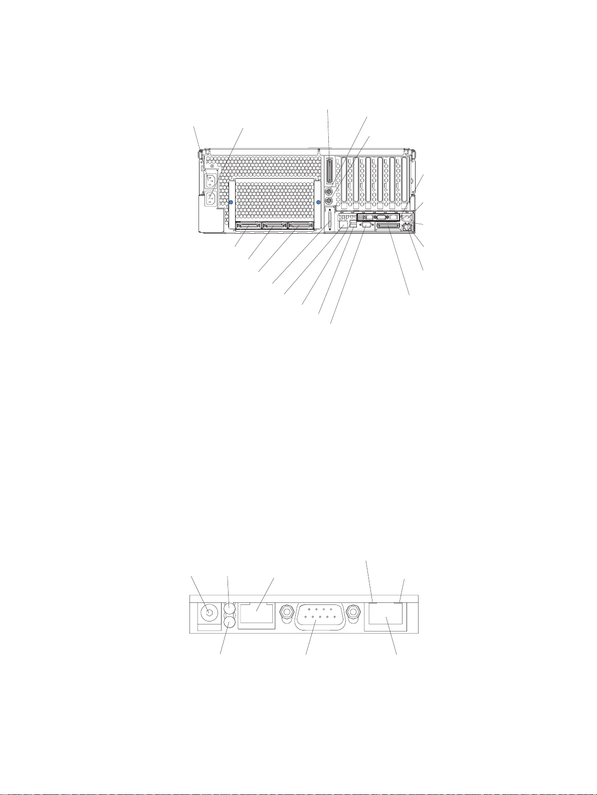
Rear view
System power
connector 1
SMP Expansion Port 1
SMP Expansion Port 2
SMP Expansion Port 3
SCSI connector
RXE Management Port
System power
connector 2
USB 1
Video connector
RXE Expansion Port B
Mouse connector
Keyboard connector
Remote
Supervisor
Adapter
connectors
and LEDs
Gigabit Ethernet
connector
Upper Ethernet
status LED
Lower Ethernet
status LED
Gigabit Ethernet
connector
RXE Expansion
Port (A)
USB 2
Figure 2. Rear view of SmartServer 370
System power connectors (1 and 2): The system power cords are connected to
these two connectors to provide power to the system.
RXE Expansion Port B: Use this port to connect the server to a remote I/O
enclosure when two SMP Expansion Modules are installed.
®
Mouse connector: Connect a mouse or other PS/2
device to this connector.
Keyboard port: Signal cables for a keyboard are connected to the keyboard port.
Remote Supervisor Adapter connectors and LEDs: This group of connectors
and LEDs located on the back of the server are used for system management
information and control.
Ethernet activity LED
External power
connector
Error LED
(amber)
Power LED
(green)
ASM interconnect
port
Figure 3. Remote Supervisor Adapter
Management port
(green)
Ethernet link LED
(green)
10/100
Ethernet port
12 User’s Guide
v External power connector - This connector is not supported on this server.
 Loading...