

Page 1
REFRIGERATOR
Contents
1. Product Specification 2
2. Safety Warning & Caution 3
3. Specification of Electric Components 5
4. Circuit Diagram 7
5. Dimension & Part Name of Refrigerator 9
6. Freezing Cycle & Cold Air Circulation
Course in Refrigerator 15
7. Function & Operating Instruction of Refrigerator 17
8. Operating Principle of Circuit 26
9. Trouble Checkup & Repair Method 34
10. Operation Principle & Repair Method of ICE-MAKER 50
11. Reference 55
12. Disassembly Method of Freezer & Refrigerator 60
13. Method of Hinge up Assembly & Disassembly 63
14. Refrigerator Exploded view & List 64
15. Machine Room Assembly Specification 89
16. Disassembly & Assembly Method of Internal Part of
Electric Field Box 90
17. Installation Method of Water Supply Tube 91
18. Installation of the Water Dispenser Line 92
19. PCB Circuit Diagram and Service Components List 93
20. Specification of Principal Part of Circuit 94
Model :
SR-S2026C(D)SR-S2226C(D
)
SR-S2027C(D)SR-S2227C(D
)
SR-S2028C(D)SR-S2228C(D
)
SR-S2029C(D)SR-S2229C(D
)
SR-S2025C(D)
SR-S20NTC(D) SR-S22NTC(D)
SR-S20BTC(D) SR-S22BTC(D)
SR-S20DTC(D) SR-S22DTC(D)
SR-S20FTC(D) SR-S22FTC(D)
SR-S20YTC(D)
Page 2
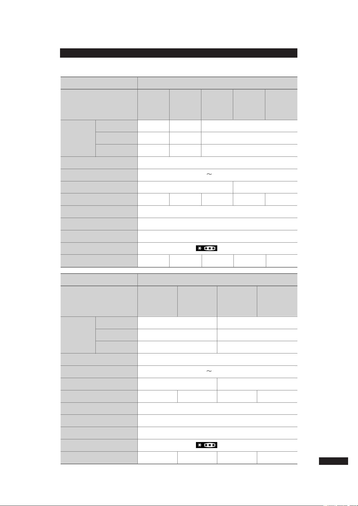
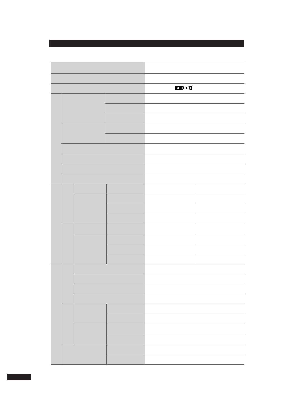
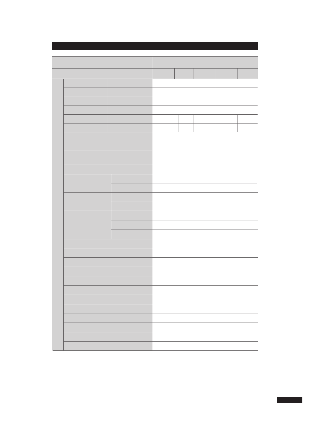
1. Product Specifications
2
562l
349l
213l
547l
336l
211l
540l
349l
191l
155W 160W
400W 410W 412W 412W 422W
111Kg 111Kg 117Kg 117Kg
Indirect Cooling Method Refrigerator
HFC-134a
190gr
(4-STAR)
908mm ✕719(724)mm ✕1760mm
230 240V/50Hz
SR-S2026C(D)
SR-S20NTC(D)
Basic
SR-S2025C(D)
SR-S20YTC(D)
Water Dispenser
SR-S2027C(D)
SR-S20BTC(D)
Basic
&
H/B
SR-S2028C(D)
SR-S20DTC(D)
Dispenser
SR-S2029C(D)
SR-S20FTC(D)
Dispenser & H/B
NNeett ddiimmeennssiioonn((WW××HH××DD))
Rated Frequency and Frequency
Motor Rated Consumption Power
Electric Heater Rated Consumption Power
Kind of Refrigerator
Refrigerant
Refrigerant Input Amount
Freezer Performance
Product Weight
Item
Specification
NNeett CCaappaacciittyy
TToottaall
RReeffrriiggeerraattoorr
FFrreeeezzeerr
MMooddeell
599l
227l
372l
569l
197l
372l
155W 160W
400W 410W 412W 422W
121Kg 121Kg 127Kg 127Kg
Indirect Cooling Method Refrigerator
HFC-134a
190gr
(4-STAR)
908mm ✕754(759)mm ✕1760mm
230 240V/50Hz
SR-S2226C(D)
SR-S22NTC(D)
Basic
SR-S2227C(D)
SR-S22BTC(D)
Basic
&
H/B
SR-S2228C(D)
SR-S22DTC(D)
Dispenser
SR-S2229C(D)
SR-S22FTC(D)
Dispenser & H/B
Outer Size (width ✕ depth ✕ height)
Rated Frequency and Frequency
Motor Rated Consumption Power
Electric Heater Rated Consumption Power
Kind of Refrigerator
Refrigerant
Refrigerant Input Amount
Freezer Performance
Product Weight
Item
Specification
Net Inside
Capacity
Total Inside Capacity
Freezer
Refrigerator
Model Name
Page 3
Read all instructions before using this product and keep to the instructions
in order to prevent danger or property damage.
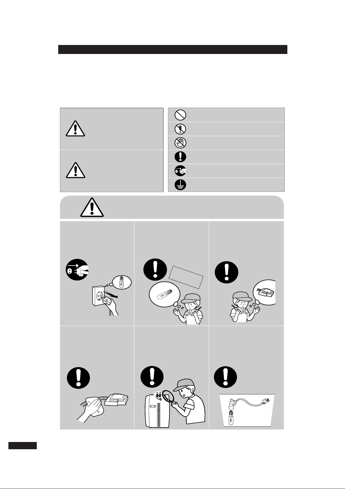
2. SAFETY WARNINGS
CAUTION/WARNING SYMBOLS DISPLAYED
SYMBOLS
Indicates that a
danger of death
or serious injury
exists.
Indicates that a risk
of personal injury
or material damage
exists.
means “Prohibition”.
means “Do not disassemble”.
means “No contact”.
means ”The things to
be followed”.
means “Earth to prevent Electric
shock”.
means “Power cord should be
unplugged from the consent”
Pull the power plug out to
exchange the interior lamp
of the refrigerator.
●●
It may cause electric shock.
Use the rated components
on the replacement.
●●
Check the correct model,rated
voltage,rated current,operating
temperature and so on.
On repair,make sure that the
wires such as harness are
bundled tightly.
●●
Bundle tightly wires in order not to
be detached by the external force and
then not to be wetted.
On repair,remove completely
dust or other things of
housing parts,harness parts,
and check parts.
●●
Cleaning may prevent the possible
fire by tracking or short.
After repair,check the
assembled state of
components.
●
It must be in the same assembled
state when compared with the state
before disassembly.
Check if there is any trace
indicating the permeation
of water.
●●
If there is that kind of trace,change
the related components or do the
necessary treatment such
as taping using the
insulating tape.
Warning
Warning & Caution
Caution
Unplug
3
Rated
components
Page 4
4
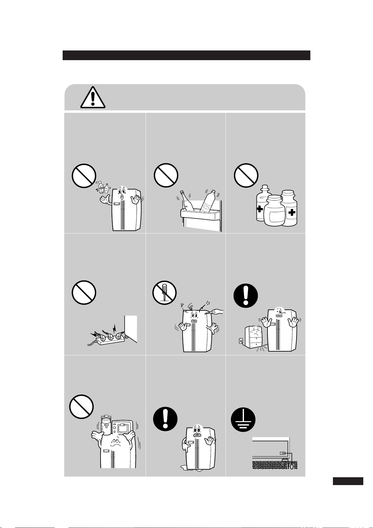
Do not allow users to put
bottles or kinds of glass in
the freezer.
●●
Freezing of the contents may inflict a
wound.
❈
Place let users know in detail.
Do not allow users to store
narrow and lengthy bottles
or foods in a small multipurpose room.
●●
It may hurt users when refrigerator
door is opened and closed resulting in
falling stuff down.
Do not allow users to store
pharmaceutical products,
scientific materials,
etc., in the refrigerator.
●●
The products which temperature
control should not be stored in the
refrigerator.
Do not allow users to insert
the power plugs for many
products at the same time.
●●
May cause abnormal generation of
heat or fire.
Do not allow users to
disassemble, repair or alter.
●●
It may cause fire or abnormal
operation which leads to injury.
Do not allow users to bend
the power cord with
excessive force or do not
have the power cord pressed
by heavy article.
●●
May cause fire.
Make sure of the earth.
●●
If earthing is not done, it will cause
breakdown and electric shock.
Do not allow users to install
the refrigerator in the wet
place or the place which
water splashes.
●●
Deterioration of insulation of
electric parts may cause electric
shock or fire.
Do not allow users to store
articles on the product.
●●
Opening or closing the door may
cause things to fall down, with may
inflict a wound.
Warning & Caution
Prohibition
Prohibition
Prohibition
Prohibition
Prohibition
Do not
disassemble
Earth
Page 5
THERMISTOR
(R-SENSOR)
502A T
Models
Freezing Capacity
Condenser
Dryer
Capillary tube
Refrigerant
SR-S20..∼SR-S22..
(4 STAR)
FREOL α- 15 (ESTER)
SPLIT FIN TYPE
SPLIT FIN TYPE
Forced and natural convection type
Molecular sieve XH-9
0.82×3000, 5.5 Kg/cm
2
HFC-134a
ON(℃) OFF(℃)
-25.0 -27.0
-19.0 -21.0
-13.0 -15.0
ON(℃) OFF(℃)
0.0 -2.0
4.0 2.0
8.0 6.0
4 hr ± 10 min
12 ~ 24 hr (vary according to the conditions used)
6 ~ 12 hr (vary according to the conditions used)
10 ± 2 min
THERMISTOR (502AT)
5.0㏀ at 25℃
THERMISTOR (502AT)
5.0㏀ at 25℃
AC 250V 10A
77 ± 4℃
Items Specification
Components for Freezer
Room Temperature Sensor Components
Freezer
Model
Temperature Selection
-26℃
-20℃
-14℃
THERMISTOR
(F-SENSOR)
502A T
Model
Temperature Selection
-1℃
3℃
7℃
Refrigerator
Defrost Cycle
Defrost Sensor
F Defrost-
Sensor
R Defrost-
Sensor
Thermal-Fuse
First Defrost Cycle (Concurrent defrost of F and R)
Defrost Cycle(FRE)
Defrost Cycle(REF)
Pause time
Model
SPEC
Model
SPEC
Rated
Operating temperature
Defrost Related Components
Compressor
Model
Starting type
Oil Charge
Evaporator
Freezer
Refrigerator
DK182Q-L2U
R.S.C.R
3. Specifications of Electric Components
5
Page 6
Electric Components
230 W
110 W
41 W
25 W
-
-
-
10W
5W
-
5W
10W
230 W
110 W
41 W
25 W
SR-S2029, S2229
SR-S20FTC,S22FTC
SR-S2028, S2228
SR-S20DTC,S22DTC
AC 250V 10A 72±4℃
Specifications
Items
Model
Conducting at F Defrosting
Conducting at R Defrosting
Conducting at F Defrosting
Conducting at R Defrosting
Interlock with F-FAN
Interlock with COMP
Defrost-Heater(FRE)
Defrost-Heater(REF)
DRAIN Heater(FRE)
DRAIN Heater(REF)
DISPENSER Heater
HOME-BAR Heater
Condenser for
COMP
(Package type)
Running
Starting
Model
Operation
Model
Temp. ON
Temp. OFF
Starting-Relay
Over-load Relay
MOTOR-BLDC(FRE)
MOTOR-BLDC(REF)
MOTOR-BLDC (Circuit)
Lamp(FRE)
Lamp(REF)
Door Switch
Door Switch (HOME-BAR)
Dispenser Switch
Power cord
Earth Screw
Thermal-Fuse for preventing
overheating of Freezer Defrost-Heater
DK182Q-L2U
350VAC-5μF
-
J531Q35E330M385-2
33Ω±20%
4TM265RFBYY-53
130 ±5℃
69 ±9℃
230V/50,60Hz
240V/50Hz UDQMOO2H4ASS
240V/50Hz UDQMOO2H4ASS
240V/50Hz UDQMOO2H4ASS
AC240V/25W
AC240V/25W×2
AC250V 0.5A×2
AC250V 0.5A
DECO 250VAC 6A
AC250V 12A
BSBN (BRASS SCREW)
Thermal-Fuse for preventing
overheating of Refrigerator Defrost-Heater
Compressor
Rated Voltage
6
SR-S2027, S2227
SR-S20BTC,S22BTC
SR-S2026, S2226
SR-S20NTC,S22NTC
SR-S20YTC,
SR-S2025
Page 7
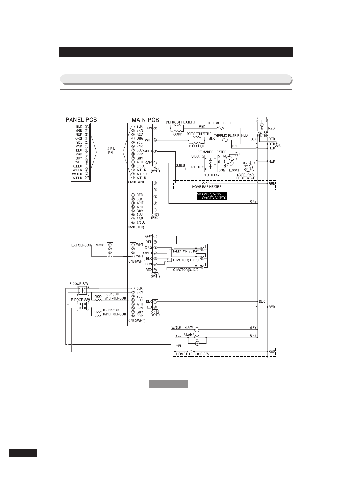
4. Circuit Diagram
7
For Basic &&With Home Bar Models
(SR-S2025, S20YTC, S2026, S2027, S2226, S2227/S20NTC,S20BTC,S22NTC,S22BTC)
RED-RED
BLU-BLUE
ORG-ORANGE
P/BLU-PINK/BLUE
BRN-BROWN
PNK-PINK
GRY-GRAY
W/BLU-WHITE/BLUE
WHT-WHITE
YEL-YELLOW
BLK-BLACK
PRP-PURPLE
W/BLK-WHITE/BLACK
S/BLU-SKY/BLUE
E-EARTH
W/RED-WHITE/RED
Reference
Page 8
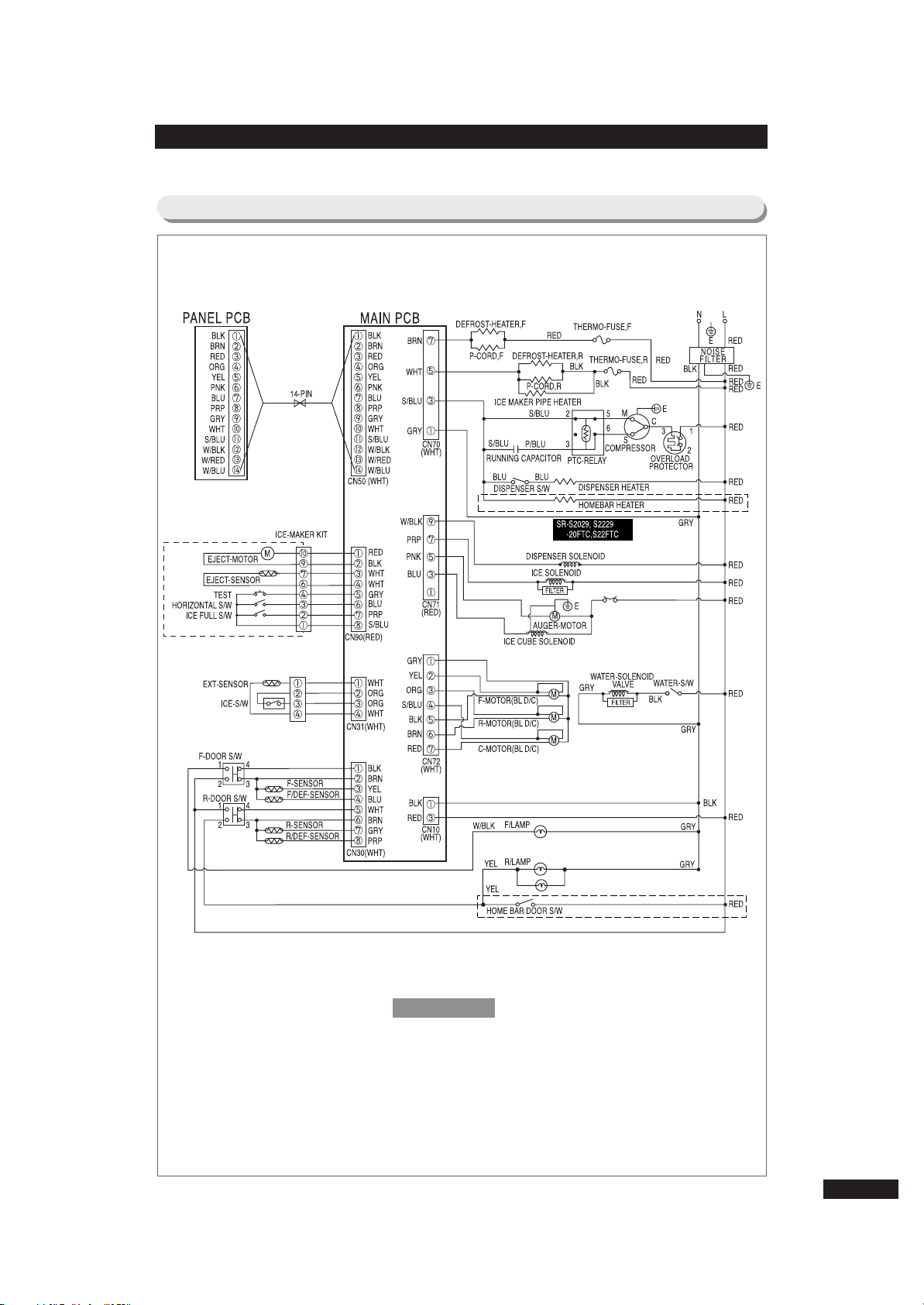
For Dispenser &&With Home Bar Models
(SR-S2028, S2029 S2228, S2229/S20DTC, S20FTC,S22DTC,S22FTC)
8
RED-RED
BLU-BLUE
ORG-ORANGE
P/BLU-PINK/BLUE
BRN-BROWN
PNK-PINK
GRY-GRAY
W/BLU-WHITE/BLUE
WHT-WHITE
YEL-YELLOW
BLK-BLACK
PRP-PURPLE
W/BLK-WHITE/BLACK
S/BLU-SKY/BLUE
E-EARTH
W/RED-WHITE/RED
Reference
Page 9
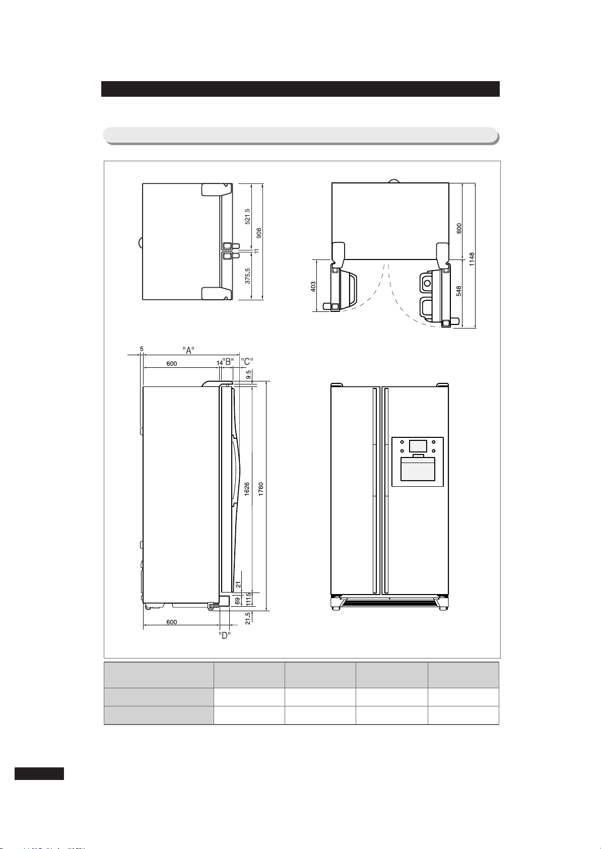
5-1) Product Dimension
(SR-S2025, S2-YTC)
(SR-S2025, S20YTC
MODEL
SR-S2025C, S20YTC
SR-S2025D, S20YTC
“A” “B” “C” “D”
719
714
50
50
55
50
54
54
5. Dimension &&part name of refrigerator
9
Page 10
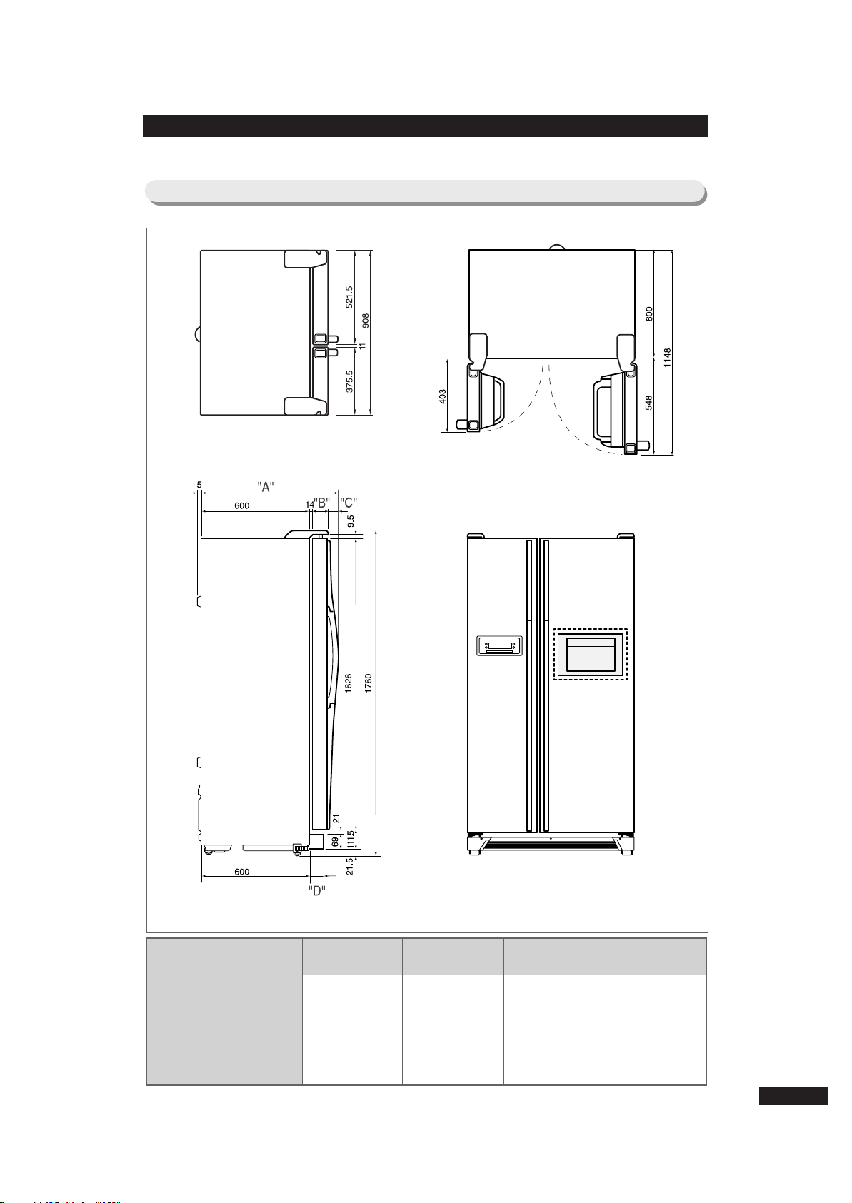
5-2) Product Dimension
(SR-S2026, S2027, S2226, S2227/S20NTC,S20BTC,S22NTC,S22BTC)
(SR-S2027, S2227)
-S20BTC,S22BTC
MODEL
SR-S2026C, S2027C/S20NTC,S20BTC(D)
SR-S2026D, S2027D/S20NTC(D),S20BTC(D)
SR-S2226C, S2227C/S22NTC,S22BTC(D)
SR-S2226D, S2227D/S22NTC(D),S22BTC(D)
“A” “B” “C” “D”
719
714
754
749
50
50
85
85
55
50
55
50
54
54
89
89
10
Page 11
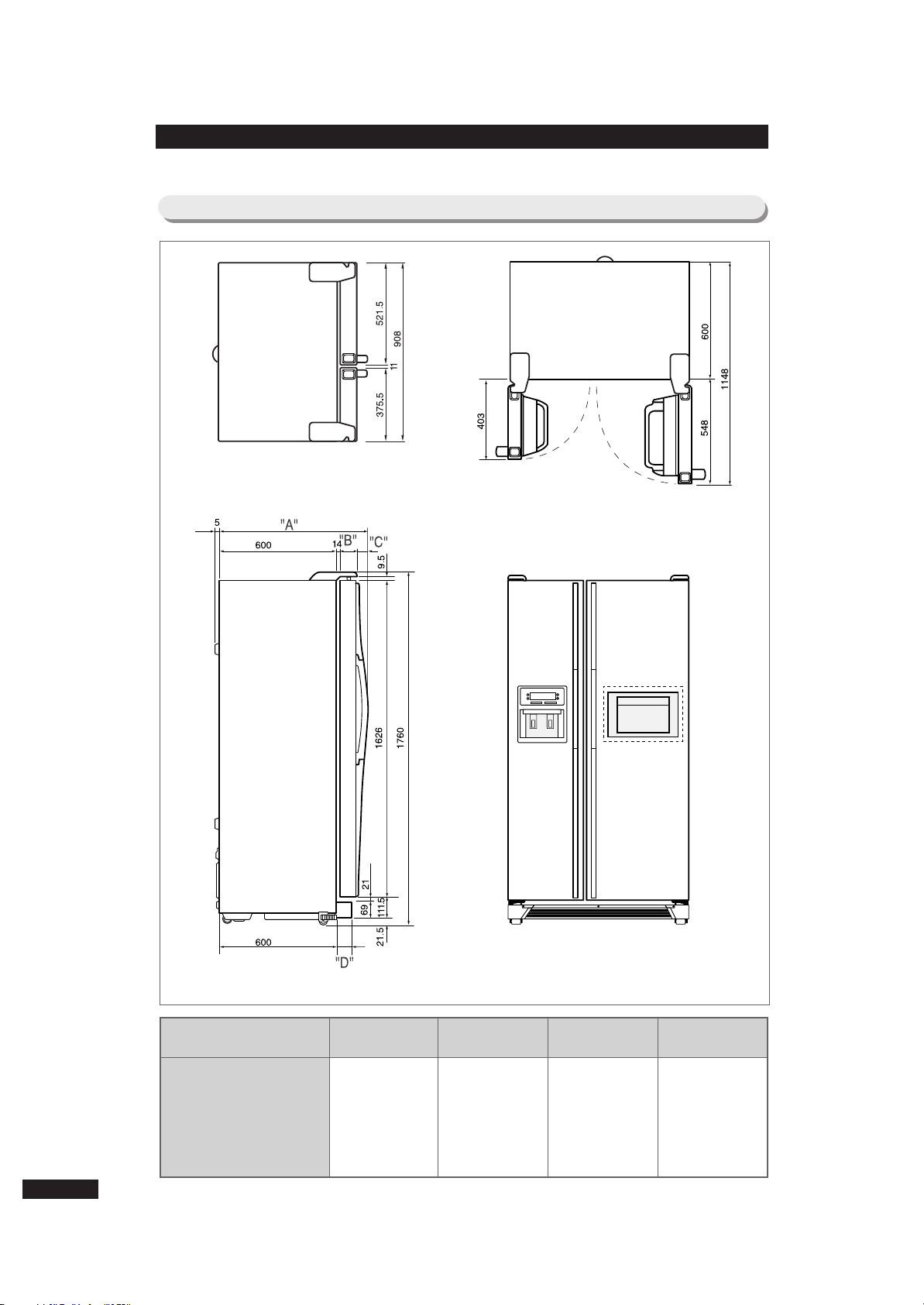
5-3) Product Dimension
(SR-S2028, S2029, S2228, S2229/S20DTC,S20FTC,S22DTC,S22FTC)
(SR-S2029, S2229)
-S20FTC,S22FTC
MODEL
SR-S2028C, S2029C/S20DTC,S20FTC(D)
SR-S2028D, S2029D/S20DTC(D),S20FTC(D)
SR-S2228C, S2229C/S22DTC,S22FTC(D)
SR-S2228D, S2229D/S22DTC(D),S22FTC(D)
“A” “B” “C” “D”
719
714
754
749
50
50
85
85
55
50
55
50
54
54
89
89
11
Page 12
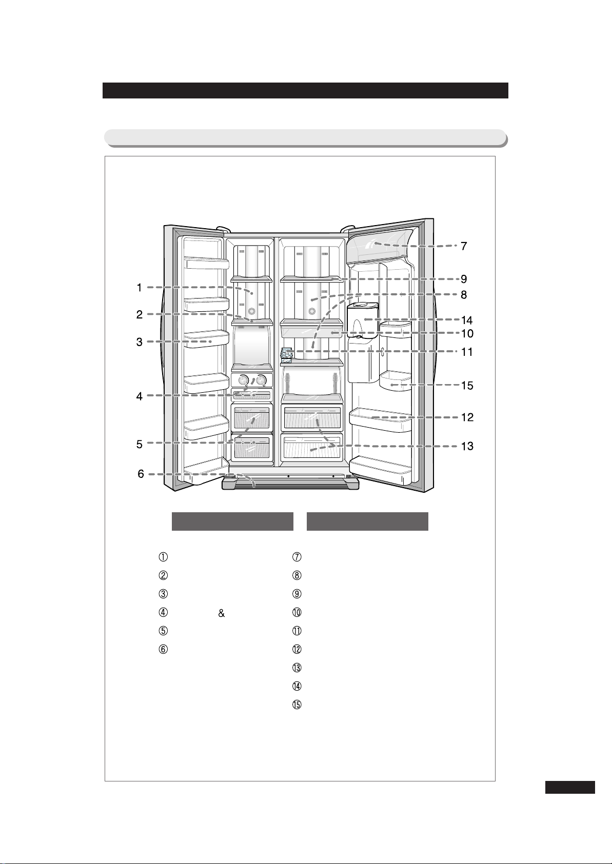
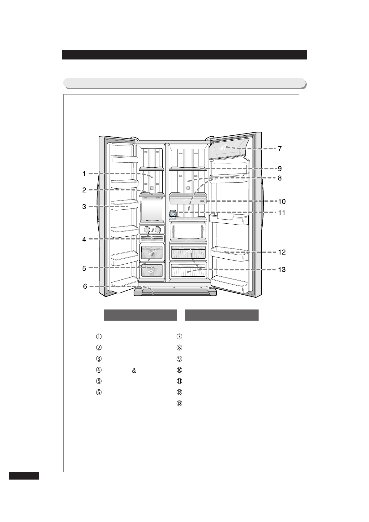
FFRREEEEZZEERR
LAMP-INCANDESCENT
SHELF
GUARD
TRAY-ICE ICE
CASE-BASKET
COVER-LEG, FRONT
RREEFFRRIIGGEERRAATTOORR
COVER-GUARD
LAMP-INCANDESCENT
SHELF
TRAY-CHILLED ROOM
TRAY-EGG
GUARD
CASE-VEGETABLE
TANK-WATER ASS’Y
GUARD-VARIETY
5-4) Part Name (SR-S2025 / SR-S20YTC)
12
Page 13
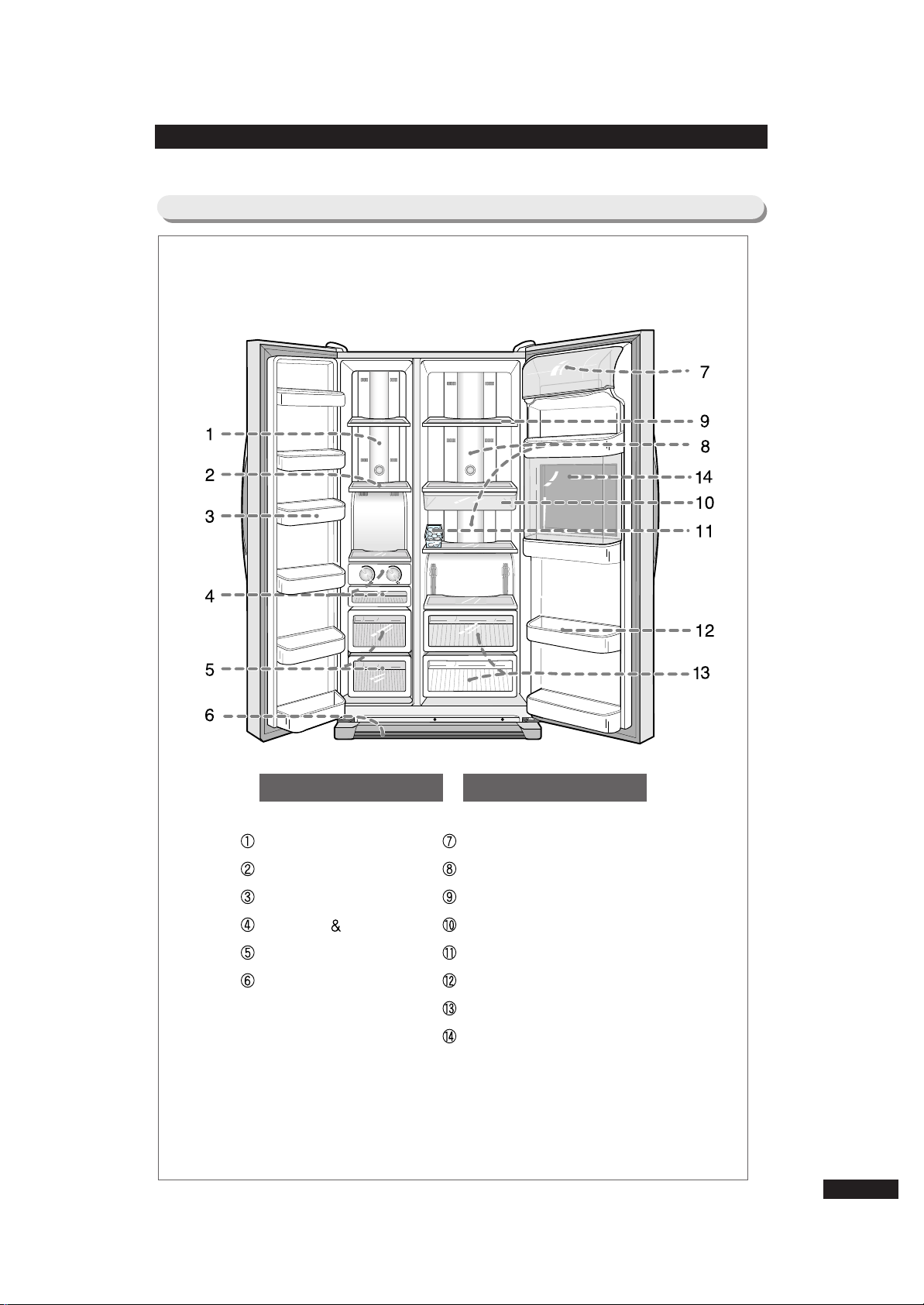
FFRREEEEZZEERR
LAMP-INCANDESCENT
SHELF
GUARD
TRAY-ICE ICE
CASE-BASKET
COVER-LEG, FRONT
RREEFFRRIIGGEERRAATTOORR
COVER-GUARD
LAMP-INCANDESCENT
SHELF
TRAY-CHILLED ROOM
TRAY-EGG
GUARD
CASE-VEGETABLE
5-5) Part Name (SR-S2026, S2226/S20NTC,S22NTC)
13
Page 14
FFRREEEEZZEERR
LAMP-INCANDESCENT
SHELF
GUARD
TRAY-ICE ICE
CASE-BASKET
COVER-LEG, FRONT
RREEFFRRIIGGEERRAATTOORR
COVER-GUARD
LAMP-INCANDESCENT
SHELF
TRAY-CHILLED ROOM
TRAY-EGG
GUARD
CASE-VEGETABLE
HOME-BAR
5-6) Part Name (SR-S2027, S2227/S20BTC,S22BTC)
14
Page 15
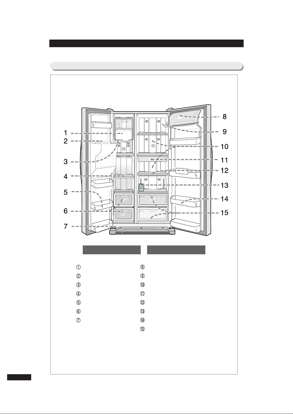
FFRREEEEZZEERR
ICE-MAKER
ICE-CHUTE
LAMP-INCANDESCENT
SHELF
GUARD
CASE-BASKET
COVER-LEG, FRONT
RREEFFRRIIGGEERRAATTOORR
COVER-GUARD
SHELF-WINE
LAMP-INCANDESCENT
TRAY-CHILLED ROOM
SHELF
TRAY-EGG
GUARD
CASE-VEGETABLE
5-7) Part Name (SR-S2028, S2228/S20DTC,S22DTC)
15
Page 16
16
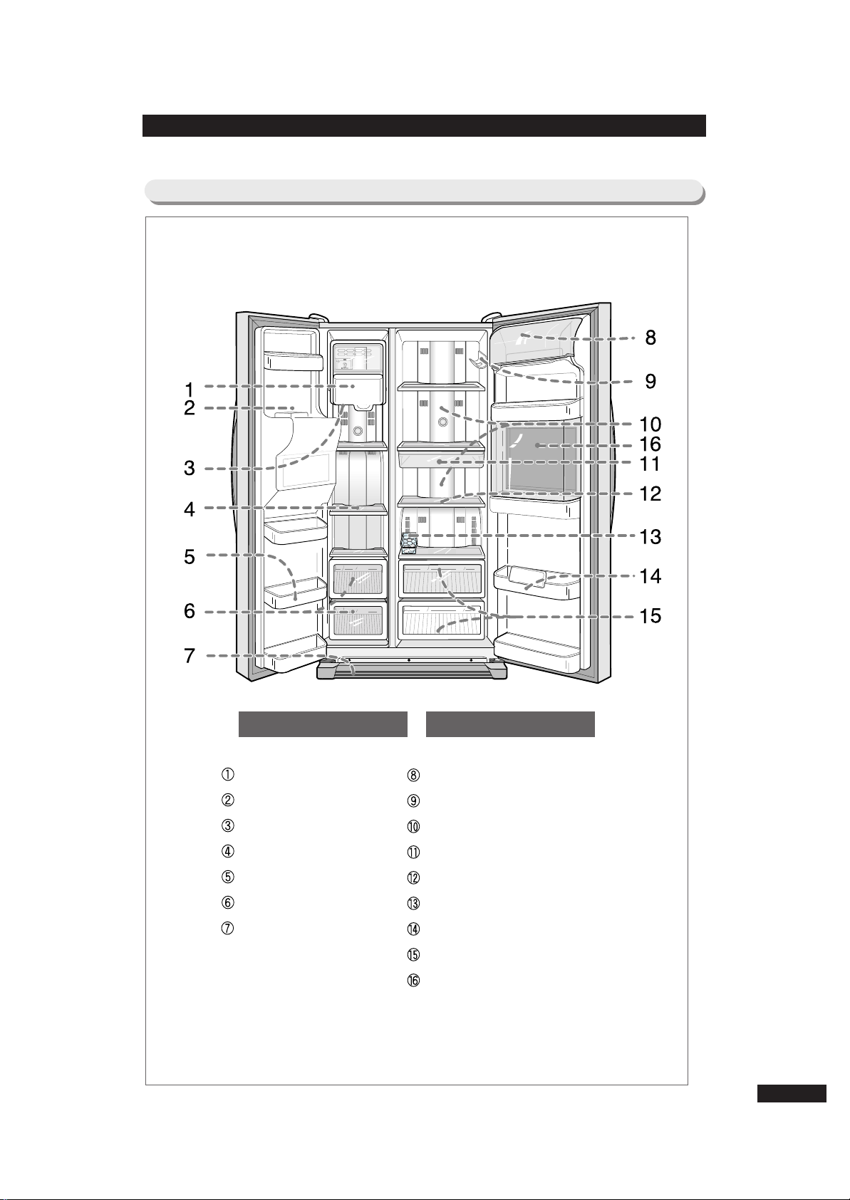
FFRREEEEZZEERR
ICE-MAKER
ICE-CHUTE
LAMP-INCANDESCENT
SHELF
GUARD
CASE-BASKET
COVER-LEG, FRONT
RREEFFRRIIGGEERRAATTOORR
COVER-GUARD
SHELF-WINE
LAMP-INCANDESCENT
TRAY-CHILLED ROOM
SHELF
TRAY-EGG
GUARD
CASE-VEGETABLE
HOME-BAR
5-8) Part Name (SR-S2029, S2229/S20FTC,S22FTC)
Page 17
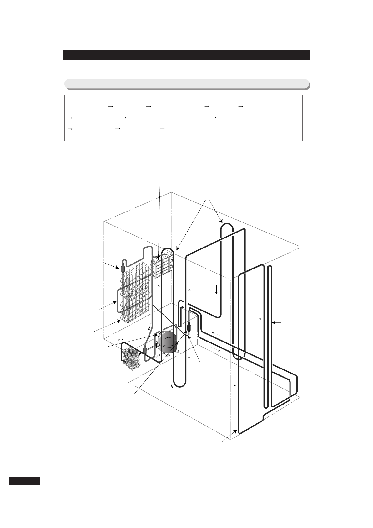
6. Freezing Cycle & Cold Air Circulation Course in Refrigerator
COMPRESSOR WIRE-COND SIDE CLUSTER PIPE HOT PIPE DRYER
CAPILLARY TUBE REFRIGERATOR EVAPORATOR FREEZER EVAPORATOR
ACCUMULA TOR SUCTION PIPE COMPRESSOR
6-1) Freezing Cycle
REFRIGERATOR EVAPORATOR
CAPILLARY TUBE
ACCUMULATOR
FREEZER
EVAPORATOR
SUCTION PIPE
DRYER
WIRE-CONDENSER
HOT-PIPE
HOT-PIPE
COMPRESSOR
SIDE CLUSTER PIPE
17
Page 18
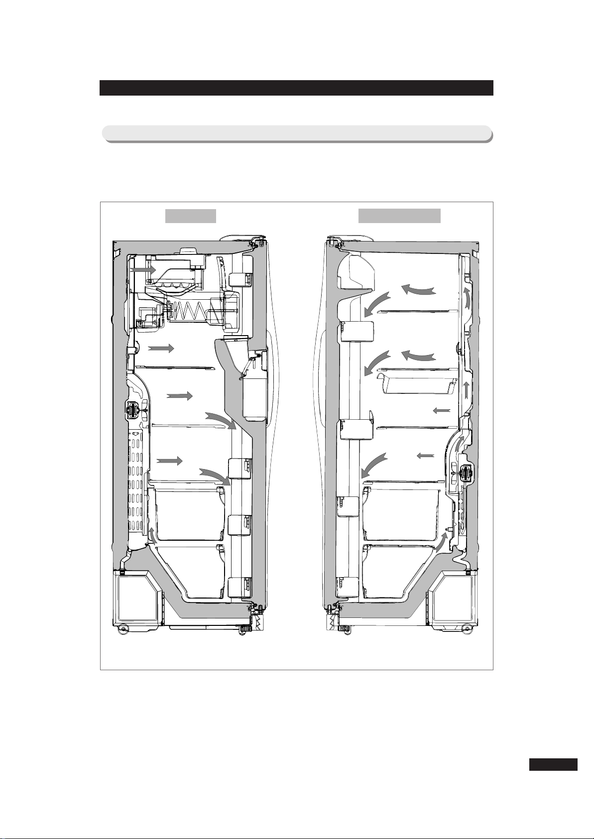
6-2) Cold Air Circulation Course in Refrigerator (Cold Air Passage Circulation Course)
FFRREEEEZZEERR
RREEFFRRIIGGEERRAATTOORR
18
Page 19
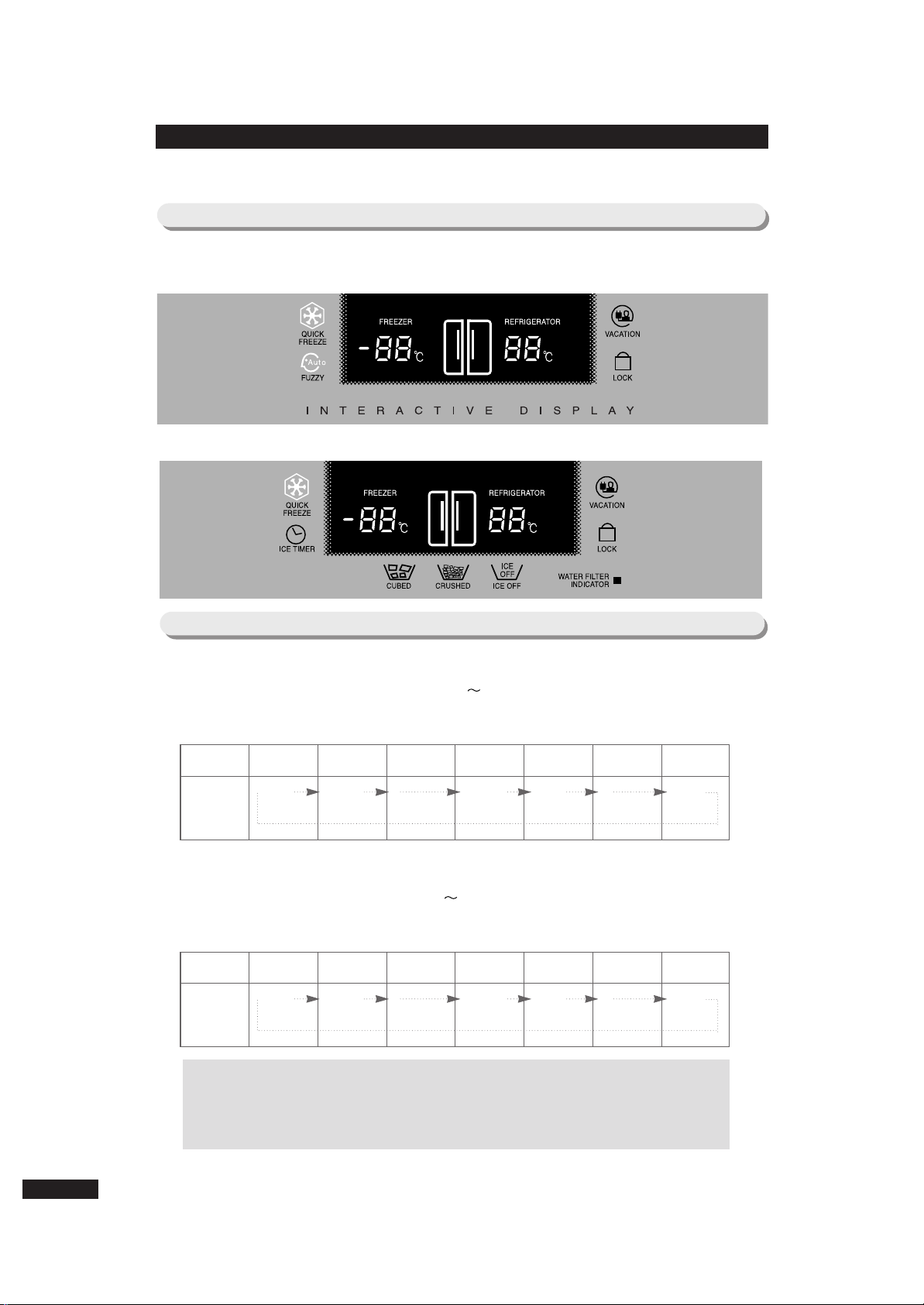
7. Function & Operating Instruction of Refrigerator
7-1) Temperature Control Function
11)) BBaassiicc aanndd wwiitthh HHoommee BBaarr MMooddeellss
22)) DDiissppeennsseerr aanndd wwiitthh HHoommee BBaarr MMooddeellss
7-2) Temperature Control Function
① Temperature selecting function of freezer
1) At initial Power On, -20˚C is selected automatically.
2) Select one button for 13 levels of -14˚C -26˚C.
3) 1˚C drops per each pressing of temperature selection button of freezer.
➁ Temperature selecting function of Refrigerator
1) At initial Power On, 3˚C is selected automatically.
2) Select one button for 9 levels of 7˚C -1˚C.
3) 1˚C drops per each pressing of temperature selection button of Refrigerator.
Division
At Initial Power On
One Time Press
● ● ●
6 Times Press
7 TimesPress
● ● ●
12 TimesPress
Display
Change
Division
At Initial Power On
One Time Press
● ● ●
4 Times Press
5 TimesPress
● ● ●
8 TimesPress
Display
Change
4
˚C
❋ Reference (terms explanation)
1)F Room: freezer 2) R Room: Refrigerator 3) F-FAN: fan motor in
freezer 4) R-FAN: fan motor in Refrigerator 5) COMP: compressor
19
7
˚C
-1
˚C
2
˚C
3
˚C
-19
˚C
-14
˚C
-26
˚C
-21
˚C
-20
˚C
Page 20

● Select extra Quick Freeze & Vacation button.
● Whenever Quick Freeze & Vacation button is pressed, selection/ cancellation
(corresponding lamp On/Off) is repeated.
● When Quick Freeze & Vacation is selected, temperature setup of freezer and
Refrigerator does not change.
● At state of selecting Quick Freeze & Vacation, change of temperature setup of freezer
and Refrigerator is possible.
① Quick Freeze Function
1) When Quick Freeze function is selected, COMP and F-FAN operates
continuously for 2 and half hours.
2) While Quick Freeze function is working, Refrigerator operates under
present setup condition.
3) When Quick Freeze function is completed (after continuous operation of
COMP, F-FAN for 2 and half hours), Quick Freeze lamp lights out
automatically and operates according to setup temperature of freezer.
➁ Vacation Function
1) When Vacation is selected, Refrigerator fan is turned off.
2) Though Vacation function is selected, Refrigerator fan does not turned off
but turned on for initial 5 minutes.
3) When Vacation function is selected and Ice Timer is set, Vacation function
completes automatically when Ice Maker works by Ice Timer function.
Then Refrigerator fan operates according to temperature setup of
Refrigerator. (explained in detail at Ice Timer function)
4) Vacation function is selected/ canceled by Vacation button. It can be
canceled by temperature control button of Refrigerator while Vacation function
is selected.
5) While Vacation function is working, Vacation lamp is ON, and temperature
display of Refrigerator is OFF.
7-3) Function of Quick Freeze & Vacation
20
Reference
Temperature of table on previous page is temperature of center part of
1/3 height of Refrigerator/Freezer compartments. It is temperature data at
unload state. When actually used, temperature may differ according to
surrounding condition and use frequency. The table displays general
characteristic of temperature.
❋ Reference
If Quick Freeze function is selected when freezer temperature is over -10˚C
and Refrigerator temperature is over +10˚C like the condition of initial
Power ON, Refrigerator Fan becomes OFF until freezer temperature
drops under certain temperature. When freezer temperature becomes
under certain temperature, Refrigerator Fan operates.
Page 21

7-4) Alarm Function
① Button Touch Sound (“Ding-Dong” Sound)
1) Input confirmation sound of “Ding-Dong” sounds when each button of
Control Panel is pressed.
2) “Ding-Dong” doesn’t sound if more than two keys are pressed at the
same time or buttons are wrongly operated.
➁ Door-Open Alarm Sound (“Ding-Dong” Sound)
1) If door of freezer or Refrigerator remains open over 2 minutes, alarm
sounds ten times.
2) If door remains open continually afterward, alarm repeats ten times per one minute
cycle.
3) Alarm stops immediately when door of freezer or Refrigerator is closed.
➂ Forced Operation & Forced Defrost Alarm Sound (“Beep” Sound)
1) If forced operation or forced defrost is selected, “Beep” sound occurs.
2) If forced operation is selected, alarm sound occurs until automatic
cancellation (after 24 hour’s forced operation) or cancellation function is
selected.
3) Also in case of forced defrost, alarm sound occurs until defrost is
completed (including pause) or cancellation function is selected.
7-5) Defrost Function
① At time of initial Power On, defrost function works for both freezer and Refrigerator at
the same time, when integrating time of Comp On is over 4 hours.
➁ Afterward defrost cycle is changeable according to use condition or surrounding
environment from 6 hrs. to 38 hrs..
➂ After completing the initial defrost, PRE-COOL function works for 20 min. to minimize
temperature increase by defrost work. However, PRE-COOL function is determined
according to temperature in Refrigerator at the point of defrost time.
➃ If F-room temperature is over -21˚C, PRE-COOL function works for F-room. If F room
temperature is below -21˚C, PRE-COOL function does not work.
21
Page 22

7-6) Test Function
● Test function is for test, process inspection and SVC of PCB and product.
● After selecting test S/W and confirming function of product, turn on power switch
again to operate self-inspection function.
● If you press Quick Freezer Key on Display Panel and temperature control Key in
R-room for more than 8 seconds, all Displays will be turned off and continue
operating in Test Mode. At this moment, if any key is pressed among freezer
temperature control key, Refrigerator temperature control key, quick freeze key or
vacation key, it operates as the test button.
❈ F-room : Freezer, R room : Refrigerator
① Forced Operating Function
1) In the state where display panel was converted into test mode, if test button
is selected once, COMP will operate immediately without 5 minute
delay function. Therefore, forced operation is conducted at the very moment
of COMP OFF, over load may be caused. Please be careful.
2) If forced operation is selected, freezer and Refrigerator is set to automatic,
and the temperature of freezer is set to “-26˚C”and Refrigerator is set to
“1˚C”, Comp and F-fan operates continuously, and R-fan in Refrigerator is
controlled by “1˚C”setup.
3) Forced operation is valid for 24hrs. That is, if 24hours. pass after
selecting forced operation, simultaneous defrost in both Refrigerator and
freezer is automatically carried out. And normal operation is carried out
by present setup of Refrigerator and freezer.
4) Cancellation of forced operation in the middle of working is possible by
turning on Power after turning it off (resetting), or by selecting test cancel
mode shown in the item 3 below.
5) When forced operation works, alarm sound will continue until forced
operation is completed. There is no alarm cancel function.
➁ Forced Defrost Function
1) In the state of forced operation, if display panel is converted into test mode and
press the test button once more, forced operation is cancelled immediately,
and evaporator defrost function of Refrigerator operates.
2) At this time, beep alarm sounds for 3sec. at the point of defrost, and
0.75sec. ON/0.25sec. off sound occurs during forced defrost function
of Refrigerator works.
3) If above defrost function of Refrigerator is maintained, it operates normally
after defrost is completed.
4) While forced defrost function of Refrigerator operates, pressing the test
button once more enables simultaneous defrost for both freezer and
Refrigerator.
5) At this time, beep alarm also sounds for 3sec. at the point of defrost, and
0.75sec. ON/ 0.25sec. off sound occurs continually until simultaneous
defrost of F and R is completed.
➂ Test Cancel Mode
1) In the state of simultaneous defrost of freezer and Refrigerator, if display panel
is converted into test mode, and test button is pressed once more, defrost
of both freezer and Refrigeration is cancelled immediately and resumes
normal operation .
22
❈ Reference
It works step by step in test function. It does not change from 1 step
(forced operation) to 4 step (test cancel mode) directly. It operates
corresponding function only after it goes through the previous step. While
test function works, it is most desirable to turn off main power and then turn it on.
Page 23
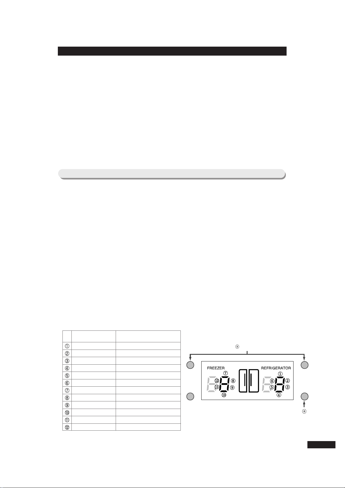
7-7) Self-diagnosis Function
① Self-diagnosis Function at the time of initial power is on.
1) When the initial power is applied to Refrigerator, all lamps light and conduct
self-diagnosis function internally.
2) If result shows no fault, display will go into the initial normal lighting state.
3) If result shows any fault, corresponding led is turned on and off and alarm
sounds.
4) Error sign of self-diagnosis continues until all defects of parts are repaired
or self-checkup function is cancelled.
5) If all corresponding parts are repaired completely, display will go into the
normal mode state.
6) After repairing Refrigerator, turn on switch again after turning it off to
make it sure if Refrigerator is properly repaired.
7) Therefore, in case open & short related problem of sensor needs to be
confirmed during A/S, turn off the power of Refrigerator and turned it on
again to operate self-Diagnosis function. Then sensor function can be
checked.
8) When any defect occurs, corresponding display signs are shown as in the
following chart.
NO Items Corresponding LED Defect Content Remark
01
02
03
04
05
06
07
08
09
10
ICE-MAKER
SENSOR
Defect of wire connecting system due to
badness of Open/Short related aspect of
Sensor which is equipped at the
beneath of ice-making bowl
When temperature sensing of Rsensor is more than +50℃ and less
than -50℃.
Refrigerator
R-sensor
Missing sensor housing of R-room,
contact defects, disconnection of wires,
defect of short-circuit sensor itself, etc.
Defect is indicated when temperature
sensing of R-sensor is more than +50
℃ and less than -50℃.
Defect is indicated when temperature
sensing of R-sensor is more than +50℃
and less than -50℃.
Refrigerator
defrost sensor
Missing sensor housing of R-room,
contact defects, disconnection of wires,
defect of short-circuit sensor itself, etc.
When normal operation is not done until iceisolating motion is attempted 3 times (only
ice-making function model corresponds).
R-fan motor
Error
F-fan motor
Error
C-fan motor
Error
Interference of Fan due to frost, etc.,
un-insertion of connector,
disconnection, etc.
Occurrence of the case where Fan Motor of
inner refrigerator room becomes to operate
under about 600rpm at the normal operation
condition or stops driving.
Interference of Fan due to frost, etc.,
un-insertion of connector,
disconnection, etc.
Un-insertion of connector,
disconnection, etc.
Defect of micro S/W in Gear box,
motor, gear and other defect in wire
system
Badness is indicated when temperature sensing
of Outside Air Sensor is more than +50℃ and
less than -50℃.
ICE-MAKER
KIT
Outside Air
Sensor
Freezer
F-sensor
Freezer
defrost-sensor
Missing of outside air sensor housing inside of PCB
base of top part of Refrigerator, contact defect,
disconnection of wires, defect of short-circuit sensor
itself, etc.
Missing sensor housing in F-room,
contact defects, disconnection of wires,
defect of short-circuit sensor itself, etc.
Missing defrost-sensor housing in evaporator of
F- room, contact defects, disconnection of wires,
defect of short-circuit sensor itself, etc
Defect is indicated when temperature
sensing of F-sensor is more than +50℃
and less than -50℃.
Defect is indicated when temperature
sensing of F-sensor is more than +50℃
and less than -50℃.
Occurrence of the case where Fan Motor of inner freezer
room becomes to operate under about 600rpm at the
normal operation condition or stops driving.
Occurrence of the case where Comp Cooling Fan
Motor becomes to operate under about 600rpm at
the normal operation condition or stops driving.
Note) This self-Diagnosis works only when the open/short related aspect of sensor is bad. Minute
feature change of sensor is not judged as defect if it does not get rid of the extent of temperature
sensor described in Remark so that it is indicated as normal.
23
Page 24
➁ Self-Diagnosis Function in Normal Operation
1) Under normal operation of Refrigerator, if you press “Quick freeze”and
“Vacation”button at the same time for 6sec., temperature setup display
will proceed On/Off blink of all for 2sec. at 0.5sec. interval.
If you press “Quick freeze”and “Vacation”button continuously at the
same time for about 8sec. including 2sec. of repetition of LED’s On/Off,
self-Diagnosis function is selected.
2) At this moment, it goes into self-Diagnosis function with“Ding-dong”
buzzer sound.
3) When Error occurs, it is restored to normal state regardless of defect
repairing after signal lasts for 30sec. (“Ding-dong”buzzer sound).
4) While it is operating self-Diagnosis function, it does not accept input of
button.
7-8) Load Condition Indicating Function
① In normal operation, if you press “Quick freeze”and “Vacation”button
at the same time for 6 sec., all setup display of freezer and Refrigerator
are turned on. If you hand off from the button at this moment, temperature
setup display of freezer and Refrigerator will proceed On/Off blink of all for
2sec. at 0.5sec. interval. While On/Off blink is processing, if you press the
temperature setup button, it goes into load condition indicating function
(with ding-dong buzzer sound).
➁ Load condition indicating mode shows from which load Micom signal
outputs at present. However, it only shows that micom signal is outputted
and does not confirm whether load is actually operating or not. That is,
even if load is displayed as it is operating, load may not operate because
of actual defect of load or defect of relay on PCB. During A/S, you can
use this function by applying the main function.
➂ Time required to indicate is 30 sec.. After 30sec., it is automatically
restored to the setup state before its function.
➃ Corresponding display indication about load condition is shown as in the
following table.
NO Display Content Operation Content
R-fan high
R-fan low
R-Def-Heater
Start Mode
Overload Mode
Low-temperature Mode
Comp
F-fan high
F-fan low
F-Def-Heater
C-fan high
C-fan low
R-fan high speed operation indication
R-fan low speed operation indication
R room defrost-heater operation indication
indication operation stage (Not important)
when ambient temperature is more than 34℃
when ambient temperature is less than 17℃
Comp operation indication
F-fan high-speed operation indication
F-fan low-speed operation indication
F room defrost-heater operation indication
C-fan high-speed rotation operation indication
C-fan low-speed rotation operation indication
Load Mode Check List
Press both buttons 6 sec, simultaneously, all LED lights are
turned on and off twice.
At this time press button .
For load under operation, corresponding LED lights on.
24
Page 25

● This function only applies to a model equipped with ice-maker.
● This function is limited to a model from which ice and water can be taken out
from outside without opening door.
① Cube Ice / Crushed Ice/ Stop (Off) Function
1) At the time of intial power on, when inside temperature of freezer is more than 5℃,
Cube Ice LED light on display is lit on, and Crushed Ice LED light keeps light-off
state. But when power is turned on, if inside temperature of freezer is less than 5℃,
Micom recalls form of ice which was set up before power off so that it displays the
memorized ice form.
2) “Cube”→“ Crushed”→“ Ice Off”is selected in turn by ice selecting Key.
3) In case of selecting “Crushed”mode, it operates Gear Motor to eject crushed ice
to outside when ice lever operates as ice is made in the bowl of ice machine.
4) In case of selecting “Cube”mode, Gear Motor and ice solenoid operate to eject
cube ice to the outside when ice lever operates as ice is made in the vessel of
ice machine.
5) If “Ice Off”is selected, it stops only ice-making function of ice-maker so
that ice is not made.
◆ At the moment of selecting “Ice Off”, ice-making function stops. But, if it is in
the process of ice-isolating, returning to horizontal state and supplying
water, it maintains stoppage state after water supply is completed.
◆ Even when “Ice-Off”function is operating, ice eject lever operates normally.
This is not a defect. Therefore, remained ice in the ice container can be used
normally.
② Ice Timer Function
1) If you press ice timer button, it is automatically set to Ice-Off mode regardless of
present setup condition of ice mode (Cube / Crushed / Ice Off), and ice lamp is
turned on. And time is set to 3 days on temperature control display of freezer at first.
And each time you press the ice button, the number increases one by one. And if it
reaches 30 days, it resumes from 3 days.
2) Among ice timer functions, if you press ice selecting key, ice timer function
is cancelled.
3) If reservation is made by ice timer button, setup temperature of freezer returns to
temperature display of freezer after 5sec.. At this moment, if ice timer button is
pressed again, it displays the previous reserved date again.1-2 days before the
reserved date is completed, ice maker starts operating. And when the reserved date
is completed, more than half of ice bucket is filled.
4) If ice timer is reserved and vacation function operates, vacation function
ends at the same time when ice timer function ends.
7-9) Function of Ice/Water Dispenser when they are equipped.
25
Page 26

5) The following are examples for use.
◆In case of selecting vacation function only
If you press “vacation”button, Refrigerator will not operate and freezer will operate
only. In case you select this function, take out all foods in the Refrigerator. And “Ice
Off”is automatically selected among ice modes, so ice bucket should be empty and
water supply valve should be turned off.
◆In case of selecting ice timer function only
In case you press “Ice Timer”button to select date as explained above, and not
selecting “Vacation”function so that Refrigerator continues to operate, ice mode is
selected as “Ice Off”and ice is stored in the bucket when you return. Therefore, do
not lock the water supply valve.
◆In case of selecting both vacation and ice timer function
In case you press “Ice Timer”button and “Ice Timer”button to select date to select
date as explained above, or if you press “Ice Timer”button to select date and press
“Vacation”button afterward, Refrigerator does not operate but freezer operates only,
and ice mode is automatically selected as “Ice Off”. So you must take out all foods in
Refrigerator, empty ice in the ice bucket, check water leakage on valves, other hoses
and connection parts without locking water supply valve. When “Vacation”function is
cancelled, Refrigerator resumes its operation.
③ Ice Dispenser Function (Cover Ice Route Solenoid Valve)
1) After 8sec. from initial power on, solenoid of ice exit operates once. This is the
function to prevent interruption of electric service when ice exit is open. So this is not
a defect.
2) With turning the dispenser S/W from on to off and ice ejecting is
completed, 5sec. after turning off S/W, ice exit is closed because cover ice
route solenoid of ice dispenser operates.
④ Water Dispenser Function
1) This function is a system of direct connection with water supply. When water lever is
pressed, water solenoid valve which is equipped at the right side of machine room
opens so as to operate to eject water. However, it has no function to control on
Micom PCB. Therefore, if there happens any defect at water eject function, check
and repair solenoid itself, wire connecting connector, connecting tube and state of
water supply.
⑤ Water Filter Indicator Function
1) After the initial power on, indication lamp is displayed in green light. After 5 months
passed, it is displayed in orange light, and 1 month after this, it is displayed in red
light. This is memorized by EEPROM in Micom PCB, so it counts the passed time
continually though the power is turned on again after it was turned off.
2) If you press ice selecting button and ice-making stop button at the same time for
25sec. continuously, indication lamp lights in green color. And it becomes orange
after 5 months from this moment. And it displays red after 1 month from the
moment.
3) If you press ice selecting button and ice-making stop button at the same time for 5
sec., indication lamp is turned off and water filter indicator function stops. At this
moment, passed time is not counted.
4) At the state where the function is stopped, if you press ice selecting button and icemaking stop button at the same time for 25sec. continuously, “Green”light is turned
on and water filter indicator function will resume. And it becomes orange light after 5
months from this moment. And it displays red light after 1 month from the moment.
26
Page 27

27
1) In case power is applied to prevent customer from nonsense call about
initialization of freezer and Refrigerator at -20℃ and 3℃ respectively when
a momentary power stoppage (not a long-term power stoppage) occurs
while Refrigerator is operating, it operates in two ways. The first one is
initialization by judging the temperature of inside of freezer, and the second
one is restoration of operation state.
2) At the initial power on, in case temperature of the inside of freezer is
judged as about less than +5℃, it is regarded as momentary power
stoppage during operation. Therefore, functions related with panel display
such as Quick Freeze, Vacation, Freezer setup, Refrigerator setup, Ice
timer, Form of ice, etc. are restored.
3) At the initial power on, in case temperature of the inside of freezer is about
more than +5℃, it is regarded as long-term power stoppage. In this case,
panel display is initialized (Quick off, Vacation off, Freezer is set to -20℃,
Refrigerator is set to 3℃, Ice timer off, Cube selecting).
4) Ice timer function and water filter indication function are not initialized in
case of power stoppage. But during power stoppage, time count does not
progress because Micom in PCB does not operate because power source is
not supplied.
7-10) Restoring Function of Operation State in case of Power Stoppage
Page 28
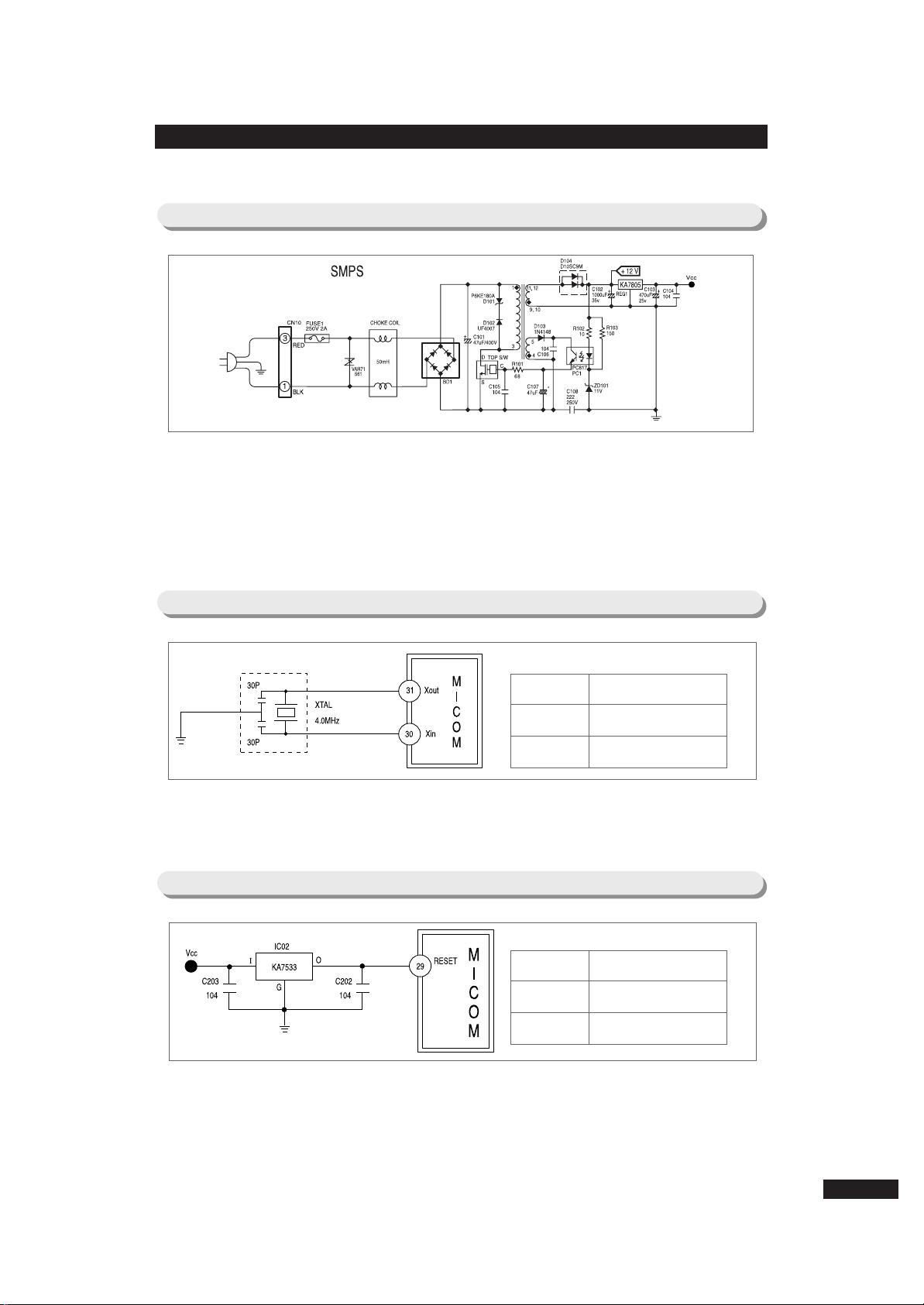
8. Operation Principle of Circuit
Terminal Oscillation Frequency
Xin(#30)
Xout(#31)
4MHz
4MHz
8-1) Power Source Part
When power is supplied, electric wave is rectified through BD1 to generate voltage of
about DC 300V.Top S/W is automatically switched to the optimum condition according to
load condition of the second part.
When electricity flows between D and S of the top S/W, electricity is generated inside
the trans, and when the power between D and S is turned off, electricity which is
deserted at trans is transmitted to the second part.
This process is repeated to maintain the fixed voltage of 12V by C102 of the second
part. This power supplies electricity to power source of 5V, relay and display, and it
allows operation of main PCB possible.
8-2) Oscillation Circuit Part
It is oscillation circuit for synchronism clock generation and time calculation on
information sending/receiving of internal elements. It does not carry out its normal
function because timing system of MICOM alters in case the specification of resonator
changes.
8-3) Reset Circuit Part
Reset circuit is a circuit which allows the whole program operate on an initial
position by initializing several parts such as RAM inside of MICOM when power is
applied to MICOM. When power is supplied, the reset terminal voltage becomes
several tens ㎲“LOW”state compared with Vcc voltage (DC 5V) of MICOM, and it
maintains “HIGH”(Vcc voltage) state in normal operation condition.
Terminal Voltage
Vcc
RESET
DC 5V
DC 5V
28
Page 29
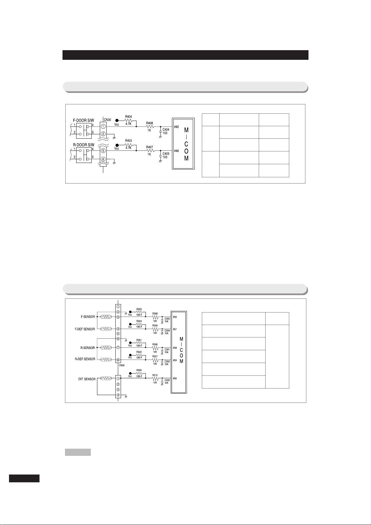
8-4) Door S/W Sensing Circuit
For door open sensing of F room, ② of CN30 is connected to the ground. For ①, Vcc(DC
5V) is supplied through resistance R404(4.7㏀), and “LOW”(0V)/”HIGH(5V) is applied to
MICOM by open/close of the F room door so that it can sense open/close of the F room
door. For door open sensing of R room, ⑥ of CN30 is connected to the ground. For ⑤,
Vcc(DC 5V) is supplied through resistance R403(4.7㏀), and “LOW”(0V)/”HIGH(5V) is
applied to MICOM by open/close of the R room door so that it can sense open/close of
the R room door. At this time, if there is any defect at the door S/W, the corresponding
fan inside the Refrigerator does not work or alarming function works. Therefore, the door
S/W must be checked in case of A/S. That is, if door opens, the corresponding fan inside
the Refrigerator stops without fail. When connection point of S/W has defect, MICOM
judges that door is open so that it stops the fan though the door is closed.
8-5) Temperature Sensing Circuit Part
Terminal
Voltage
MICOM
F-Room
DOOR CLOSE
DOOR OPEN
5V (HIGH)
0V (LOW)
R-Room
DOOR CLOSE
DOOR OPEN
0V (LOW)
5V (HIGH)
MICOM terminal Voltage
PIN #56 (F-SENSOR)
PIN #57 (F-DEF-SENSOR)
PIN #58 (R-SENSOR)
PIN #59 (R-DEF-SENSOR)
PIN #60 (EXT-SENSOR)
MICOM
terminal
voltage
changes in
accordance
with
temperature.
29
Sensor uses thermistor which has temperature coefficient of negative resistance. When
temperature rises, resistance value gets smaller, and when temperature falls, resistance
value gets larger. R306~R310, C301~C305 are parts for noise prevention, which are not
related to temperature sensing characteristic. In case of F-SENSOR, if setup voltage
inputted to MICOM Referred to as Vf, Vf= (Rth*Vcc)/(R303+Rth). Here, Rth is
resistance value of thermistor corresponding to temperature. See conversion table of
“Refer 6”of this manual on resistance and voltage of sensor about temperature for
Reference. As terminal voltage of MICOM corresponding to temperature is also
designated, Refer to it at A/S time.
Page 30
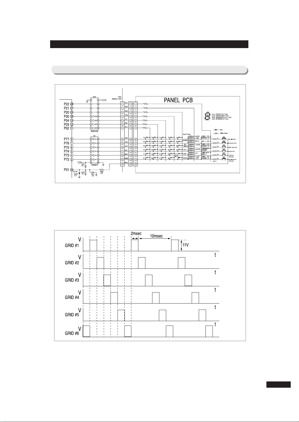
8-6) Key Scan & Display Circuit Part
① Key Scan and Display Operation
As is seen on each wave form of the following, send “HIGH”output in an
order of MICOM PIN NO #3→#4→#5→#6→#7→#8 for 2msec in a cycle
of 12msec using six terminals of MICOM NO #3, 4, 5, 6, 7, 8. This signal
appears onto output terminal through input terminal of IC05(UDN2981 or
KID65783AP). At this time, peak-to-peak voltage of the spherical wave is
about 11V(DC RMS1.5), and form of output wave form is like the drawing 1.
② Key Scan
When the wave form of GRID#2 is outputted, this signal is provided to SW6 button
through the resistance of 10㏀. When SW6 is pressed at this time, signal gets smaller
by R501(12㏀), and about 4.5V of peak-to-peak voltage is applied to MICOM.
MICOM judges that the wave form of GRID#1 is inputted, and changes function
corresponding to SW6 KEY. In this way, each wave form of GRID is recognized.
30
Page 31

8-7) Load Operation Circuit Part
When “HIGH”signal is applied to INPUT terminal of IC03(KID65003AP) from MICOM
PIN NO #16(P07), IC is turned on. At this time, V12(DC12V) which is applied to the one
terminal of coil of COMP relay flows to ground through output of IC03. Then core
generates magnetic field to turn on the connection point, and it applies voltage of 230V
to COMP load to turn on COMP. When MICOM PIN NO #16 changes to “LOW”state,
electricity cannot flow to COMP relay coil because IC is turned off. So relay connection
point becomes to OFF state and stops COMP.
① COMP & F,R Defrost Heater Inter-operation Explanation
Like the above block diagram, operation of F, R defrost heater is determined according
to the operation of relay for COMP. When COMP relay is connected to NO terminal,
COMP operates. However, in case of F, R defrost heater, electricity does not pass
through the heater though relay works. But, if COMP relay is connected to MC terminal,
COMP does not operate and heater gets electricity according to operation of F, R
defrost relay.
※ Purpose of application of above circuit: It aims to interrupt electricity passage through
F, R defrost heater even though F, R defrost relay is bad while COMP is operating.
31
Page 32

8-8) BLDC Motor Operation Circuit Part
■ In case Fan Motor is locked, therefore, when Fan Motor is constrained to less than
about 600rpm in order to prevent over-current to the power source group, PIN #39,
#38 and #37 sense it so that they can stop Fan Motor operation.
If Fan Motor operation is stopped by this function, it becomes to re-operate every 10
second. If Motor Connector is separated under the state where the power source is
applied during service, Micom recognizes it as Fan Motor is constrained so that
Micom can stop Motor. Then Motor resumes to operate after 10 seconds.
However, there are a part of products which re-operate every about 5 minute among
the products which were manufactured in February and March.
Therefore, when the product is completely repaired, confirm the repaired state with
power-ON again after power-OFF if possible.
32
Page 33

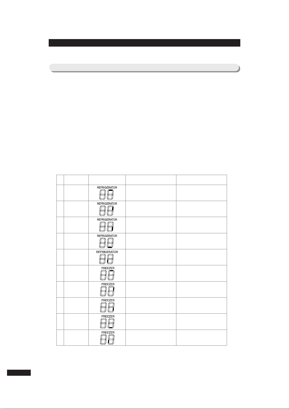
8-9) Various Option Function
■When pressing the temperature control s/w of freezer and vacation s/w for 12 sec.
continuously at the same time, display is converted into option setup mode.
■When display is converted into option setup mode, every display except for
temperature display of freezer and Refrigerator turns off like the following.
■On display like the above, temperature display of Refrigerator indicates items of
option, and temperature display of freezer indicates setup value for each
item.For the temperature display of Refrigerator, when temperature control s/w is
pressed, option items increase, and when vacation s/w is pressed, option items
decrease. For the temperature display of freezer, when temperature control s/w
is pressed, option setup value increases, and when vacation s/w is pressed,
option setup value decreases. If waiting for 20sec. after changing option by
controlling s/w, option setup value is saved to EEPROM, and option setup mode
is canceled automatically and restored normal display. For example, if you want
to shift temperature of Refrigerator by -3℃ by controlling option, follow the
processes of below.
1) Press temperature control s/w and vacation s/w of freezer for more than
12 sec. simultaneously : all displays become off except temperature
display of freezer and Refrigerator.
2) Pressing temperature control s/w of Refrigerator for one time, “1”is
indicated on Refrigerator display : If indication “1”is displayed on
Refrigerator display, it shows temperature setup of Refrigerator, and
current temperature setup value of Refrigerator is indicated on
temperature display of freezer.
3) If temperature display of freezer indicates “9”this time, check value
which is set at present from the table in the next page. In this case,
you can see that temperature is changed to +1.0℃ compared to the
standard temperature according to the table : Here, in order to change
by -3.0℃, (+1.0℃) + (-3℃) = -2.0℃ is calculated.
4) Now Refer to the table on the next page to change temperature to
-2℃. Press temperature s/w and quick freeze s/w of freezer for
temperature control display to indicate “4”: Waiting for 20sec. after
setup, MICOM saves setup value to EEPROM and returns to the
normal display and cancel option setup mode.
33
Caution
When product is delivered, option function is set to EEPROM from the plant,
therefore, Refrain from intentional change except for special case. Option
function setup is completed only after it is returned to the normal display after
20sec.. So do not turn power off before display returns to the normal state.
Page 34

■
Freezer Temperature Change Table
●Example
- When set to -2.5℃, compared with the standard
temperature of freezer
Temperature change Temperature change
Set item Refrigerator display
“0”
Freezer temperature
change mode
0
- 0.5℃
- 1.0℃
- 1.5℃
- 2.0℃
- 2.5℃
- 3.0℃
- 3.5℃
+ 0.5℃
+ 1.0℃
+ 1.5℃
+ 2.0℃
+ 2.5℃
+ 3.0℃
+ 3.5℃
+ 4.0℃
“0”
“1”
“2”
“3”
“4”
“5”
“6”
“7”
“8”
“9”
“10”
“11”
“12”
“13”
“14”
“15”
Freezer display Freezer display
Temperature change Temperature change
0
- 0.5℃
- 1.0℃
- 1.5℃
- 2.0℃
- 2.5℃
- 3.0℃
- 3.5℃
+ 0.5℃
+ 1.0℃
+ 1.5℃
+ 2.0℃
+ 2.5℃
+ 3.0℃
+ 3.5℃
+ 4.0℃
“0”
“1”
“2”
“3”
“4”
“5”
“6”
“7”
“8”
“9”
“10”
“11”
“12”
“13”
“14”
“15”
Freezer display Freezer display
Set item Refrigerator display
“1”
Refrigerator temperature
change mode
■ Refrigerator Temperature Change Table(●: corresponding lamp is on,
●: corresponding lamp is off)
8-10) Option Related to Temperature
34
●Example
- When set to +2.5℃, compared with the
standard temperature of Refrigerator
Page 35

8-11) Option Related with Ice Maker
■
Following options are applied only for models which are equipped with ice maker.
■
It is water supply time option that operates
when the flow sensor for time control
function of water-supply for ice maker is out
of order (identical with DIP s/w of existent
ZIPEL).
■
When Refrigerator temperature display indicates “2”,
the data indicated on the freezer temperature display is
the function which is not used in this model so that
additional adjustment is not necessary.
■
If Refrigerator temperature display is not selected
more than “2”during option function is setting among
models which are equipped with dispenser and icemaker, replace the main PCB assembly.
■
It is the temperature of ice making sensor
which checks whether the ice of ice-maker of
temperature change of ice making sensor
freezes completely.
Set item
Ice maker water supply time
Water supply time
“ 3 ”
5sec
4sec
3sec
6sec
7sec
8sec
9sec
10sec
12sec
13sec
15sec
17sec
19sec
21sec
23sec
25sec
“ 0 ”
“ 1 ”
“ 2 ”
“ 3 ”
“ 4 ”
“ 5 ”
“ 6 ”
“ 7 ”
“ 8 ”
“ 9 ”
“ 10 ”
“ 11 ”
“ 12 ”
“ 13 ”
“ 14 ”
“ 15 ”
Refrigerator display
Freezer display
Set item
Ice making temperature
Temperature change
“ 4 ”
- 7℃
- 6℃
- 8℃
- 9℃
- 10℃
- 11℃
- 12℃
- 13℃
“ 0 ”
“ 1 ”
“ 2 ”
“ 3 ”
“ 4 ”
“ 5 ”
“ 6 ”
“ 7 ”
Refrigerator display
Freezer display
35
●Example
- When ice making sensor is set to -10℃
●Example
- When water supply time is set to 9sec.
Note: If Refrigerator temperature control s/w and vacation s/w are used, several other options except the
above functions are set. However, those points are omitted because they are not necessary part at the
A/S time as they are items related with Refrigerator control function (Do not set options other than the
above A/S manual contents).
Page 36

9. Trouble Diagnosis & Repair Method
1. Check whether power cord is normally connected before repairs.
2. Practice checkup on the basis of Reference in the next page.
230V AC FUSE
Disconnection?
Start
Replace FUSE
power cord terminal connection
As high pressure current more
than DC300Vgenerates on the
power part of main PCB, take
great care in case of checkup
and measurement.
※
Caution
Is power 230V
applied to both terminals
of CM10?
Check cord assembly
connection.
Is voltage about
DC 320V applied to both
BD1+terminals ?
Replace PCB pattern
and BD1.
Is voltage DC5.8V
applied between top s/w
223Y ‘C-S’?
Replace PCB
assembly.
Is voltage 12V
applied to both terminals
of C102?
Replace D104(D105)
(S3L20U)(D10SC9M)
Is voltage 5V
applied to both terminals
of C103?
Replace REG1 (7805).
※
lead wire cable, door (connect
at HINGE-UP part)
Does panel PCB
operate normally?
① Check cord assembly
and repair
② Replace panel PCB
Does load of relay
and so forth operate
normally?
① Replace the
corresponding relay
② Check connection of
lead wire
Normal
Y
N
N
Y
N
Y
N
Y
N
Y
N
Y
N
Y
N
Y
Pre-checkup
9-1) When power is not supplied
36
Page 37

1. When power is applied initially, COMP works after 3~6 sec.. However, when COMP turns off during
its operation, COMP doesn’t work for 5min..
2. COMP doesn’t work during defrost
3. If freezer sensor is not connected, it is sensed as low temperature and COMP doesn’t work.
Reference 4
9-2) When COMP doesn
’’
t work
Passed 5min. after COMP off?
Start
Check after 5 min.
Reference 7
(Does alarm sound due to forced operation?)
Replace MICOM and PCB
Replace IC03 and repair
Does COMP
drive at forced
operation?
Is MICOM #1601
HIGH applied?(5V)
Repair open and
connection state
Repair sensing part
and replace PCB
Is IC03 #14 LOW
applied?(0V)
Control cord and repair
connection state
Replace COMP relay
and repair
Replace COMP RELAY
Reference 2
Is contact state of
Connector CN70, CN71
is normal?
Complete insertion of
Connector
Is COMP assembly normal?
Replace COMP ASS’Y
and repair
Cord Assembly and Connection State
N
Y
Y
N
N
Y
N
Y
Y
Y
N
Y
N
Y
N
Y
Is freezer sensor
normal?
Is temperature
sensor of main PCB is
normal?
Pre-checkup
37
Page 38

9-3) Defrost function does not work
1. At the initial power on, cooling operation is normally carried out. However, after a certain time
passes (when defrost time comes), badness occurs on Refrigerating and freezing work. It is
a case where there is defect on defrost part. Checkout whether there is defect on defrost
system by Referring this trouble diagnosis.
Judgment Condition
1. If each EVA-SENSOR of F room and R room has open or short-related defect, electricity
does not flow to defrost heater and it returns to normal operation after pause time passes.
Therefore, if the period when defrost heater does not work accumulates, Refrigerating and
freezing badness results.
2. If temperature fuse which is a safety device is turned off, or defrost heater has wire
disconnection, or relay on PCB is bad, defrost is done by natural temperature rise. In this
case, period of COMP off according to defrost becomes very long so that badness on
Refrigerating and freezing function results.
Reference
Is F, R defrost
sensor normal by
self-diagnosis?
Start
Replace and repair the
corresponding sensor
Refer to load defect checkup on
this manual Ref 3.
Refer to 7-7 self-diagnosis
function of main function.
Judge in accordance with Ref 4
and Ref 8 on this manual.
Refer to 7-6) test function of the
main function.
Is F, R defrost
heater normal by
self-diagnosis?
Check temperature fuse, heater
itself, cord disconnection, cord
contact state
Is temperature
of corresponding defrost sensor
below -5℃?
Forced operation for certain
time
Perform forced defrost for F and R
simultaneously.
Is power applied
to each defrost heater?
A
B
N
N
Y
Y
N
Y
N
Y
38
Page 39

Does it return to
cold operation after heating for
certain time?
When temperature of F, R
defrost sensor reach more than +5℃
and +15℃ by heating, terminate
heating and convert into cooling
operation after pause.
Normal
Repair connection terminal
Refer to load operation circuit
part and checkup method on
relay defect on Ref 2
N
Y
A
Recheck troubles of corresponding
sensor that does not return.
Is connection terminal
of MAIN-PCB part normal?
Check troubles on corresponding
defrost heater relay, badness of PCB,
and defect on normal/close terminal
connection of COMP RELAY.
Replace and repair bad relay or
replace PCB ASS’Y
N
Y
B
39
Page 40

9-4) Self-diagnosis Abnormality Occurs
① When abnormality on outer temperature sensor occurs
Is insertion of
main PCB connecter(CN31)
normal?
Start
Repair badness on
connector contact or
omission
Is outer temperature
sensor forging normal?
Replace temperature
sensor
Is voltage input of
MICOM PIN #60 normal?
Check main-PCB cold
lead or short
No defect on PCB and temperature
sensor. Recheck connector contact
badness
N
N
Y
Y
N
Y
② When abnormality of temperature sensor of Refrigerator occurs
Is outer temperature
sensor forging normal?
Start
Replace temperature
sensor.
Is insertion of
MAIN-PCB connector(CN30)
normal?
Badness on connector
contact. Re-insert.
Is connection cord
between main-PCB connector
(CN30) sensors?
Disconnection of wire
between connector and
sensor.
No defect on PCB and temperature
sensor. Recheck connector contact
badness
N
N
Y
Y
N
Check cold lead, short,
lead touch.
N
Y
Is input voltage of
MICOM PIN #58 normal?
Y
Reference 4
Reference 4
40
Page 41

③ When abnormality on defrost sensor of Refrigerator occurs.
Is insertion of
MAIN-PCB connector(CN30)
normal?
Start
Repair contact badness on
connector(CN30) and un-
inserted part
Replace temperature sensor
Repair the un-inserted
Connecter or contact badness.
Is defrost sensor
forging normal?
Is connection
between defrost sensor and
connector normal?
No defect on PCB and temperature
sensor. Recheck connector contact
badness
N
N
Y
Y
N
Y
Check cold lead, short and
lead touch
Is voltage input of
MICOM PIN#59 normal?
N
Y
④ When abnormality on temperature sensor of freezer occurs
Is insertion of main-PCB
connector(CN30) normal?
Start
Repair contact badness on
connector(CN30) and un-
inserted part.
Is defrost sensor
forging normal?
Replace temperature sensor
Is connection
between defrost sensor and
connector normal?
Repair the un-inserted
Connecter or contact badness.
No defect on PCB and temperature
sensor. Recheck connector contact
badness
N
N
Y
Y
N
Check cold lead, short and
lead touch
N
Y
Is voltage input of
MICOM PIN#56 normal?
Y
41
Reference 4
Reference 4
Page 42

⑤ When abnormality on defrost sensor of freezer occurs
Is insertion of
MAIN-PCB connector(CN30)
normal?
Start
Repair contact badness on
connector(CN30) and un-
inserted part.
Is defrost sensor
forging normal?
Replace temperature sensor
Is connection
between defrost sensor and
connector normal?
Repair the un-inserted
Connecter or contact badness.
No defect on PCB and temperature sensor.
Recheck connector contact badness
N
N
Y
Y
N
Check cold lead, short and
lead touch
N
Y
Is voltage input of
MICOM PIN#57 normal?
Y
Reference 4
9-5) When alarm is continuously ringing
·Alarm for freezer/Refrigerator door open continues for 10sec. at the initial door open. After 2 min. of
initial opening, it alarms for 10sec. by the 1min.
cycle when door remains open (10 times of Ding-Dong sound).
Reference
① When Ding-Dong sound continuously occurs
Is there any
penetration of moisture to
door s/w?
Start
Replace DOOR S/W
Do input voltages
of MICOM PIN #45, #46
change?
Repair cord disconnection and
badness DOOR S/W
Is insertion of
MAIN-PCB connector(CN30)
normal?
Repair the un-inserted
Connecter or contact badness.
MAIN-PCB and DOOR S/W are
normal
N
N
(DOOR OPEN/CLOSE)
Y
Y
N
Replace DOOR S/W
N
Y
Is DOOR S/W itself normal?
Y
42
Page 43

② When “Beep-Beep”sound continuously occurs
Isn’t forced
operation or defrost
selected?
Start
Cancel forced operation or
defrost.
Does buzzer
sound occurs if power
is reset?
MAIN-PCB is normal
Check dirt insertion and short on test
jumper part inside of the MAIN-PCB
N
N
Y
Y
Sound of “Beep-Beep”does not occur except abnormalities due to forced operation, defrost or
self-diagnosis abnormality.
In case of self-diagnosis abnormality, it is easy to check because it is indicated on panel-display.
If “Beep-Beep”sound continues to ring though panel display is normal, it is considered that
forced operation or defrost is selected.
Reference
③ In case PANEL-DISPLAY is not lit
Is connector
insertion of HINGE-UP cover
normal?
Start
Re-insert connector, repair
badness on contact
Is insertion of MAIN-PCB
connector(CN50) normal?
Re-insert connector inside
of the MAIN-PCB.
Is connector
insertion of the panel dispenser
part normal?
Re-insert connector, repair
badness on contact.
Replace PANEL-DISPLAY
N
N
Y
Y
N
Y
43
Page 44

④ When key selection of PANEL-DISPLAY is not available
Is connector insertion
of HINGE-UP 14PIN of freezer
normal?
Start
Re-insert connector.
Repair contact badness
Repair on the basis of
connection diagram of electric
wire assembly cabinet-door of
Reference 1.
Is connector(CN50)
insertion on the MAIN-PCB
normal?
Re-insert CN50 connector,
correct and repair.
Is connector insertion
of the PANEL-PCB part
normal?
Re-insert connector,
correct and repair.
Is there any case
that more than one key are pressed
in a series?
Reassemble PCB base,
resolve pressed part.
Continuous operation is
impossible
Is it badness of
ZD501 or short-related defect on the
MAIN-PCB
Replace and repair
ZD501.
Is GRID signal
inputted to MICOM PORT
#34?
Replace and repair the
MAIN-PCB ASS’Y
Check if corresponding GRID
signal is inputted when PANEL-PCB
S/W button is pressed.
Repair corresponding button of
PANEL-PCB, or replace PANEL ASS’
Y PCB
N
N
Y
Y
N
Y
N
Y
Y
N
N
Y
44
Page 45

Check sensing circuit on PCB related
with F-DOOR S/W. Replace and repair.
Judge on the basis of
abnormality of DOOR S/W in
“check item”of this manual Ref 5.
Check only at the condition where
Refrigerator door is closed.
Refer to checkup method of relay
badness on Ref 2.
9-6) When FAN does not work
“Check cooling fan only at the condition of selecting forced operation necessarily.”
1. When COMP is turned off, cooling fan of freezer(F-FAN), cooling fan of Refrigerator(R-FAN),
COMP, and cooling fan of COMP mostly retains “off”state. However, in case of R-FAN, it can
operate for some period of time by natural defrost function if COMP is turned off.(It operates
depending on temperature condition of Refrigerator)
2. Evenat forced operation condition, R-FAN is not always turned on (including normal operation),
and retains “off”state if temperature of Refrigerator room is reached the set temperature.
3. When the door of freezer and Refrigerator is closed after opening, each fan has its delay time. That
is, fan stops immediately when door is opened during its operation, and operates again after
delay of about 10sec. or 1min. (when outer temperature is over 35℃) when the door is closed.
Reference
① When FAN of freezer(F-FAN) does not work (when COMP operates normally by temperature).
Is COMP in “off”state?
Start
Allow forced operation.
Open freezer door
Is F-FAN turned off?
Replace and repair MAIN-PCB ASS’Y.
Y
N
N
F-FAN is normal.
Y
Y
When pressing
F-DOOR S/W, does FAN operate after
delay time?
N
Badness of fan itself. Replace
and repair
Y
Is voltage of
DC7~11V applied to both terminals
of fan?
N
Re-insert connector and
repair.
N
Is contact of CN72 on
PCB normal?
Y
45
Page 46

Check sensing circuit on PCB
related with R-DOOR S/W. Replace
and repair.
Judge on the basis of
abnormality of DOOR S/W in
“check item”of this manual Ref 5.
Is COMP in “off”state?
Start
Let forced operation.
Open refrigerator door to raise
temperature inside of refrigerator
Is R-FAN turned off?
Replace and repair the MAIN-PCB
ASS’Y
Y
N
N
R-FAN is normal
Y
Y
With pressing
R-DOOR S/W, does fan operate after
delay time?
N
Badness on fan itself. Replace
and repair.
Y
Is voltage of
DC7~11V applied to the both terminals
of FAN?
N
Re-insert connector and repair.
N
Is contact
of CN72 on the PCB
normal?
Y
② When Refrigerator fan (R-FAN) does not work (when temperature sensing function in
Refrigerator room is normal).
46
Page 47

9-7) When lamp inside of Refrigerator is not lit.
There exists the risk of electric shock when replacing the lamp inside of
Refrigerator. Replace and repair at only “power off”state.
Is connector contact
inside of Refrigerator
normal?
Start
Re-insert connector and
repair.
Is filament of LAMP broken?
Replace LAMP in the
Refrigerator.
Is there any
abnormality on connection point of
R-DOOR S/W?
Check if voltage of 230V is applied
to socket of R-LAMP and repair.
N
Y
Y
N
N
Y
Inside of cover of Refrigerator LAMP
※
Check on the basis of
abnormality checking method for
DOOR S/W of Ref 5.
Check and repair R-DOOR S/W.
Caution
47
Page 48

9-8) When lamp inside of freezer is not lit.
There exists the risk of electric shock when replacing the lamp inside of freezer room. Replace and repair
at only “power off” state.
Caution
Is connector
contact inside of freezer
normal?
Start
Re-insert connector and
repair.
Is filament of LAMP broken?
Replace LAMP in the
freezer.
Is there any
abnormality on connection point of
F-DOOR S/W?
Check if voltage of 230V is applied
to socket of F-LAMP and repair.
N
Y
Y
N
N
Y
※
Inside of cover of FREEZER-LAMP
※
Check on the basis of abnormality
checking method for DOOR S/W of Ref 5.
Check and repair F-DOOR S/W.
48
Page 49

9-9) Abnormality diagnosis method for ICE-MAKER
Is DC electricity
(5V, 12V) normally outputted?
Is ICE-MAKER
dish horizontal?
Badness of power
resource terminal
Replace the
MAIN-PCB
Power Resource
Terminal Check
Disconnect
connector like
Ref. 8
Kit Check (CN90
Terminal WIRE
HARNESS)
Sensor Check
(Ref. 4)
Motion Check
Is resistance between
both ends (between ① and ②) of ice-eject motor within
range of 18~22Ω?
N
N
N
Y
Y
Y
Badness on
motor
Is TEST S/W(both ends
of ⑤ and ⑧) open?
N
Y
Badness on
TEST S/W
Is horizontal S/W(both
ends of ⑥ and ⑧) open?
N
Y
Badness on
MICRO S/W
Is ice-check S/W (both ends
of ⑦ and ⑧) open?
N
Y
Badness on
MICRO S/W
Is ice-eject sensor
(both ends of ③ and ④) within range written on
table of Ref. 8?
N
N
Y
Y
Badness on ice-
eject sensor
Pressing test s/w for more than
1.5sec., does it normally perform ice-eject and horizontal
restoration and generate sound of “Ding-Dong”
for one time?
Badness on kit
ASS’Y
Replace kit
ASS’Y
Normal
49
Page 50

① When cube ice does not come out when cold cube ice is selected.
When cube ice is
selected, does cube ice
come out?
Start
Isn’t freezer door open? Close
the door if it is open.
When ice lever is
operating, does cube ice
come out?
Normal
N
Y
Y
Replace and repair MAIN-PCB
ASS’Y
N
N
Is micro port #20 on
MAIN-PCB “HIGH”?
Y
Replace and repair relay RY76.
N
Is relay K76 turned on?
Y
Check lead wire and repair
defected part
N
Re-check the water supply
point.
N
Does drill motor
solenoid inside of freezer operate
normally?
Is tap water normally supplied?
Y
Y
When motion system is normal, however, if there is no ice in the ice container, ice does not come
out. Please ensure whether there is ice in the ice container.
Reference
9-10) When cube and crushed ice are not normally operated.
50
Page 51

Does S/V operate for
0.3 sec. when 8 sec. are passed after initial
power on?
Start
Check and repair
devices such as
stopper lever &
support, etc
No defect on S/V control PCB ASS’Y
and wire system
When ice lever is
pressed, does it maintain
open state?
Replace MAIN-
PCB ASS’Y
Badness of IC03.
Exchange
Utilize checkup
method for SSR
defection of Ref. 2
At door-closed state,
does ice conveying motor operate if ICE S/W is
turned on?
Is cover closed
after about 5sec. by S/V
operation?
No defect on cover ice-route control
system
N
Y
N
N
N
N
Y
N
Y
Y
Y
N
Y
MICOM control port is normal
After 8sec. from the point
of initial power on, does IC03 #12 indicate “LOW”
state for 0.3sec.?
Check ICE S/W.
Check and repair
wire connection
system
With the initial power on,
does MICOM #18 on PCB indicate “HIGH”
state for 0.3sec.?
9-11) When solenoid which is cover ice-route delay device does not work
1. Check whether solenoid automatically operates for 0.3sec. regardless of open/close of cover
ice-route 8 sec. after initial power on.
2. Check whether Hinge-up connector contact is normal.
Pre-checkup
51
Exchange defected parts
after checking SSR71 or
replace PCB ASS’Y.
S/V is abbreviation of Solenoid Valve
Reference
Page 52

Performance of motion to retain horizontal level
of ice-making dish for initial power apply or for
restoration from stoppage of electric current.
Performance of ice-separation regardless of
water supply to ice-making dish by waiting for 1
cycle.
After ice-making is finished, motion of iceseparation from ice on dish into storage
container. Ice-separation is performed by
checking the horizontal s/w, and the signal
change of ice-inspection s/w and the changed
time. They should be checked together in parallel.
After ice-making is finished, motion to supply icemaking water to ice-tray using water valve.
Is it horizontal?
Start
ice-eject motor
stop
Wait for 1 cycle
(under -7℃)
Ice-eject step
Water supply
step
This step means the period from when water
supply is finished to when it is judged that water
turned into ice completely. This is judged by
parallel checkup of temperature and time.
Ice-making step
Function for cases which are needed for forced
operation for the purpose of operation test, A/S,
and cleaning.Ice-separation motion and water
supply motion are conducted continually and this
step should have priority than any other
operations.
Test step
Y
N
Reverse-
rotation of ice-
eject motor
10. Operation Principle & Repair Method of ICE-MAKER
10-1) Operation Principle of ICE-MAKER
52
Page 53

10-2) Ice-maker Test Function
5. Test Function
●It is function for the case which needs forced motion for the purpose of cleaning and
so on at the time of operation test and A/S. This function is performed when the test
s/w which is equipped with the body of automatic ice-maker itself, is pressed for
more than 1.5 sec..
1) Test button does not go into test function during ice-eject, levelling for horizontal
position and water supply. It operates in the horizontal state. It does not operate at
the state where ice is fully filled. Only after ice full mode is cancelled and ice-check
s/w is off, test function operates.
2) When test button is pressed in the horizontal state for more than 1.5sec., ice-eject
motion starts immediately regardless of conditions of ice-making
container. Therefore, if test function operates in the state where water does not
freeze yet, water may be poured. So, care should be taken. After ice-eject motion,
1cycle of water supply is carried out in horizontal levelling movement. Therefore, the
problems of ice-eject movement, horizontal levelling movement, and water supply
can be checked by the test button. At this time, when the test function operates
normally, buzzer sound “Ding-Dong” occurs and starts water supply function. Hence,
if buzzer sound “Ding-Dong” doesn’t occur, it may be considered that there is some
abnormality so that check and repair are indispensable.
3)When water supply is finished, it operates in normal cycle of ice-making→
ice-eject→ horizontal restoration→ water supply in order.
<Case Where Test Function does not Work>
6. Function according to F-Room Door Open
●This is function to minimize noise occurrence by stopping operation basically
when door F-room opens.
1) If F-room door opens while ice-eject or horizontal levelling is working, the function
stops immediately at this point of time. When the door is closed, function operates
normally.
2) In case water is being supplied, normal function is performed regardless of door
open of F-room.
3) Accordingly, when F-room door is opened to check, if tray leans or its angle deviates
from horizontal position, it is considered that it stops during ice-eject or horizontal
levelling movement. It doesn’t matter to judge it as a defect if it is not in horizontal
position after more than 30sec. passes when F-room door is closed to keep
horizontal state after water supply. In case it stops by F-room door open while it is
operating, Test function doesn’t work because it is actually working. So, after
finishing water supply, test function operates.
NO
Item Measures to Operate Remark
under operation
Ice is full
After finishing ice-eject, horizontal levelling and completion of water supply
After removal of ice in ice container
Turn ice-check lever On → Off.
01
02
53
Page 54

10-3) ICE-MAKER Circuit Part (Limited to equipped model)
Above ice-maker circuit is one about a kit which is equipped at the freezer. Water
supply to ice-making container is performed by operating AC solenoid which is
located in the machine room through relay so that water is supplied by open/close
time of valve. This circuit is H/W for embodiment of functions such as eject of icemaking container, horizontal levelling, ice-making temperature sensing and full-ice
sensing. Temperature sensing part is identical to that of the main H/W, and
horizontal(Hor/Inv) S/W, Ice-check(Lever) S/W and sensing circuit are identical to
those of the main H/W. So, explanation about this is omitted here, and only ice-eject
motor driving circuit part is explained.
When rotating motor in the counter-clockwise direction(CCW), if signal of
Micom Port No #10 is outputted to High. When pressure of IC05 is applied,
the voltage is applied of +12V by output of IC05 17, and the current is supplied to
IC04 of ⑪ through motor. At this time, ⑥ terminal of IC04 is connected with CCW
Port together so that output port of the corresponding IC04 ⑪ is turned on.
Therefore, current flows to the ground and motor rotates inversely.
When it moves to clockwise direction(CW), CW Port #9 is outputted by “HIGH”. The
functions of ice-eject and horizontal levelling are performed by the operation of IC
Port through right direction rotation movement.
For the points related with operation of above circuit, refer to the explanation of icemaker function of our SVC Manual.
54
Page 55

10-5) Operation of Ice-Maker
1. Connect the water-supply line to the supplying valve of the refrigerator to
supply water.(See the water tube connection procedure)
2. Push bucket to the end so that guide-ice of ice-maker is not in contact with the
end of bucket.(If the end of bucket is in contact with the guide-ice of the ice-maker,
the ice-maker will determine that there is enough ice and does not make ice
thereafter.)
3. With a newly installed refrigerator, allow about 6 hours for the refrigerator to
make ice normally and discard the made ice several times to remove impurities.
4. To get enough ice stored in the storage bin, use the ice dispenser normally after
operating the ice-maker for about 24 hours.
10-4) Designation of major components of Ice-Maker
(TRAY-ICE)
(EJECT-SENSOR)
COVER-SENSOR
SCREW
SUPT-RUBBER
FIXER-SENSOR
ICE-MAKER, KIT
(EJECT-MOTOR)
HOR-SWITCH
TEST-SWITCH
GUIDE-ICE
KNOB-TOUCH
Push the bucket to the end so that the
GUIDE-ICE of the ICE-MAKER is not in
contact with the end of bucket.
LEVER-SWITCH
55
Page 56

10-7) Assembly of Ice-Maker
1. Fit the rear rising of the ICE-MAKER KIT to the front slot of the TRAY ICE.
2. Lift FIXER-CASE at the front of the SUPT-ICE MAKER up. (① direction)
3. Place the top rising of the ICE-MAKER KIT to the slot of SUPT-ICE MAKER for
insertion.
4. Push the front of the ICE-MAKER KIT while maintaining the position.
(Be careful. If you overpush the ICE-MAKER KIT, the fixed rising of the SUPTICE MAKER may be damaged.)
5. When the front of the ICE-MAKER KIT is sagging, it means the assembly is not right.
At that case, perform the assembly again.
10-6) Disassembly of Ice Maker
1. Pull out the bucket from the freezer.
2. Disassemble the SUPT-ICE MAKER, which fixes the ice-maker, and the wire housing
in the rear of the maker.
3. Disassemble by lifting the SUPT-ICE and FIXER-CASE in the front of the maker up
(① direction) and pulling the ICE-MAKER KIT out to the front (② direction).(Do not
disassemble each component of the ICE-MAKER KIT. Otherwise, the setting value
may be changed.)
REAR RISING
FIXER-CASE
FRONT SLOT
ICE MAKER KIT TOP RISING
Wire housing
FIXED RISING
56
Page 57

1 1. Reference
Contact Point
Division
Coil and Trigger Two Terminal Voltage
Two Terminal Contact Point
3 Contact
Point
Relay
DC about 12V
(Movement Condition)
DC About 0V
(Stop Condition)
Between C and NO
Between C and NC
0Ω(SHORT)Normal
∞Ω(OPEN)Normal
∞Ω(OPEN)Normal
0Ω(SHORT)Normal
0Ω(SHORT)Normal
∞Ω(OPEN)Normal
About4㏀∼5㏀(SHORT)Normal
∞Ω(OPEN)Normal
Between C and NO
Between C and NC
Contact Points Between Two terminals
Contact Points Between Two terminals
Contact Points Between Two terminals
Contact Points Between Two terminals
2 Contact Point
Relay
SSR
DC About 12V(Load Movement condition)
DC About 12V(Load Stop Condition)
DC About 12V(Load Movement condition)
DC About 12V(Load Stop Condition)
Reference No. 1) Electric Wire Assembly Cabinet-door Connection Drawing
Reference No. 2) Test Method of Relay Defect
First, separate housing which is connected to load
connection part(Main PCB CN70~CN71). Check the
following items (Judge by voltage and resistance value).
1. Judge whether relay moves or not by measuring
voltage of both coil terminals.
2. Judge whether SSR moves or not by measuring
voltage of two trigger terminals.
3. Load contact point of two terminals are measured by
resistance value. Whether there is fault or not is
judged by comparing with voltage conditions of coil
and trigger.
Note) NC→Normal Close(C Terminal and Common ON Terminal)
NO→Normal Open(C Terminal and Common OPEN Terminal)
C →Common Terminal
Note) SSR: Solid State Relay (No Contact Point Electric Type Relay)
57
Page 58

Reference No. 4) Fault Check Method of Various Sensors
After separating connector from the MAIN-PCB,
measure resistance of sensor forging, and judge
fault existence.
1. Freezer Sensor CN 30, measure resistance value between
and
2. Refrigerator Sensor CN30, measure resistance value between
and
3. F-Defrost Sensor CN30, measure resistance value between
and
4. R-Defrost Sensor CN30, measure resistance value between
and
5. Outside Air Sensor CN31, measure resistance value between
and
6. Compare above measurement value with temperature of
location of each sensor. Also compare with sensor resistance
and voltage conversion table about temperature of Ref. 8 of
this manual. And judge whether there is any defect.
※At this time, when measuring ∞Ωor 0Ω, check wire assembly
condition.
Load
Measure Terminal
Fault Item Remark
Cube Solenoid
(F-Room Inside)
Cover Solenoid
(F-Door)
AUGER
MOTOR
HOME-BAR
HEATER
Ice Solenoid
(Machine Room)
R-Defrost
Heater
F-Defrost
Heater
Between CN70 ⑦
and CN10③
Between CN71⑤
and CN10③
I/M Application Model
I/M Application Model
I/M Application Model
I/M Application Model
H/B Application Model(check
connectionterminal only after separation)
Between CN71 ⑦
and CN10③
Between CN71 ⑦
and CN10③
Between CN71 ⑨
and CN10③
Between CN71 ⑤
and CN10③
Check resistance of the red and
sky blue line of R-door side
0Ω
∞Ω
0Ω
∞Ω
0Ω
∞Ω
0Ω
∞Ω
0Ω
∞Ω
0Ω
∞Ω
0Ω
∞Ω
Badness of temperature, fuse, heater, electric wire short-circuit
Badness of temperature, fuse, heater, and electric wire disconnection
Badness of motor coil and wire short-circuit
Badness of motor coil and wire short-circuit
Badness of coil and wire short-circuit
Badness of coil and wire short-circuit
Badness of coil and wire short-circuit
Badness of coil and wire short-circuit
Badness of coil and wire short-circuit
Badness of coil and wire short-circuit
Badness of coil and wire short-circuit
Badness of coil and wire short-circuit
Badness of heater wire short-circuit
Badness of heater wire short-circuit
Reference No. 3) Load Defect Checkup
After separating power cord from power
source plug socket, separate connectors
CN10, 70, and 71 of the main PCB, and
check the following items.
1. Measure load terminal and resistance value
between terminals like the following to check
whether there may exist defects of load and
electric wire connection.
Note) COMP parts can be changed by Capacitor, PTC, and Over Load Protector. Therefore, they
are checked by existence of movement.
58
Page 59

59
Reference No. 5) Check Door S/W Fault & Ice Lever S/W Check Method
Check in state that power is applied.
Door S/W is 2 contact-point circuit;
one contact-point senses door
open/close with DC 5V on PCB, and
the other contact-point lets refrigerator
inside lamp fluorescent On/Off.
(R-Room Lamp Part)
1. When refrigerator door is opened, check whether lamp is lit up or not. If it is normal,
check whether lamp lights out or not when pressing DOOR S/W in the state that RDOOR is open. If any faults are found, check DOOR S/W of R-ROOM door.
(MAIN-PCB Sensing Part for R-ROOM Door Open )
1.Check voltage by applying “+” terminal to CN30 and “-” terminal to .
2. When R-ROOM door is opened, if about DC 5V is measured, it is normal.
3. When R-ROOM door is closed, if about DC 0V is measured, it is normal. If any faults
are found, check DOOR S/W and wire connection system.
(F-Room Lamp Part)
1. When freezer door is opened, check whether lamp is lit up or not. If it is normal, check
whether lamp lights out or not when pressing door S/W in the state that F-DOOR is
open. If any faults are found, check door S/W of F-ROOM door.
(MAIN-PCB Sensing Part for F-ROOM Door Open )
1.Check voltage by applying “+” terminal to CN30 and “-” terminal to .
2. When F-ROOM door is opened, if about DC 5V is measured, it is normal.
3. When F-ROOM door is closed, if about DC 0V is measured, it is normal. If any faults
are found, check DOOR S/W and wire connection system.
(Ice Eject Lever)
1. In case ice is not ejected though ice eject lever which is installed at the front part of
freezer, check like the following.
2. First, check fault existence of F-ROOM DOOR S/W. If no defect is found, separate
CN31 connector on the MAIN-PCB. Apply “+” terminal to and “-” terminal to, and check
resistance. Check it becomes 0Ω when ICE LEVER S/W was pressed. When it is
always ∞ regardless of ON/Off of S/W, check wire system and connection system.
Page 60

-35
-34
-33
-32
-31
-30
-29
-28
-27
-26
-25
-24
-23
-22
-21
-20
-19
-18
-17
-16
-15
-14
-13
68.648
65.011
61.595
58.384
55.366
52.526
49.854
47.337
44.967
42.733
40.626
38.640
36.765
34.995
33.323
31.743
30.250
28.838
27.502
26.237
25.040
23.906
22.832
4.364
4.333
4.301
4.268
4.235
4.2
4.164
4.127
4.09
4.051
4.012
3.972
3.93
3.888
3.845
3.802
3.757
3.712
3.666
3.62
3.573
3.525
3.477
Reference No. 6) Resistance of Sensor about Temp. & Voltage Conversion Table
Voltage inputted to Micom Port differs according to H/W structure. This
specification is standardized one by voltage which is applied at the time when
10㏀-F grade of partial pressure resistance is used.
Corresponding Micom Port Voltage Specifications when Sensor is Open : DC about
5V(Vcc Level)Corresponding MicomPort Voltage Specifications when Sensor Short :
DC about 0V(Ground Level)
-12
-11
-10
-09
-08
-07
-06
-05
-04
-03
-02
-01
00
01
02
03
04
05
06
07
08
09
10
21.814
20.848
19.932
19.062
18.237
17.453
16.709
16.001
15.328
14.688
14.080
14.501
12.949
12.424
11.924
11.447
10.993
10.559
10.146
9.752
9.375
9.016
8.673
3.428
3.397
3.329
3.279
3.229
3.178
3.127
3.076
3.025
2.974
2.923
2.872
2.821
2.77
2.719
2.668
2.618
2.567
2.518
2.468
2.419
2.37
2.322
11
12
13
14
15
16
17
18
19
20
21
22
23
24
25
26
27
28
29
30
31
32
33
8.345
8.032
7.732
7.446
7.172
6.910
6.659
6.420
6.190
5.970
5.759
5.557
5.363
5.178
5.000
4.829
4.665
4.508
4.357
4.212
4.072
3.938
3.810
2.274
2.227
2.180
2.134
2.088
2.043
1.998
1.954
1.911
1.869
1.827
1.786
1.745
1.705
1.666
1.628
1.590
1.553
1.517
1.481
1.446
1.412
1.379
60
Temperat
ure(℃)
Temperat
ure(℃)
Temperat
ure(℃)
Resistance (KΩ) Resistance (KΩ) Resistance (KΩ)
Voltage (V) Voltage (V) Voltage (V)
Page 61

61
Reference No. 7) Forced Operation and Defrost Input Method
(Forced Operation)
It is a function to operate COMP and F-fan immediately regardless of freezer temperature.
(Forced Defrost)
It is a function to make R defrost or R and F defrost at a time regardless of defrost time.
1. In state of forced driving, when pressing the S/W once, R room alone is defrosted. And, if pressing it once
more, simultaneous defrost of R and F is performed.: Buzzer sound occurs at forced defrost, too.
2. After making Power Off and let it be On again, cancellation is made.
1. When pressing Quick Freeze S/W and Cold room Temperature Control S/W on the Panel together more than
8sec., all displays become Off. And, four temperature corresponding S/W(Quick Freeze, Vacation, Freezer
Temperature Control, Refrigerator Temperature Control) operate by test button.
2. In the above state, when pressing any one among four control S/W once, forced operation starts.
1
2
3
4
5
6
7
8
9
10
DA41-00024A
DA41-00027A
DA41-00020A
DA41-00020B
DA32-10105H
DA32-10109Q
DA32-10109R
DA32-10109N
DA27-00002A
3301-000016
NNOO CCOODDEE--NNOO
Product Name
Specification
Quantity
Remark
Reference No. 8) Circuit Par Service Material List
Reference No. 9) Circuit Part Service Material List
F, R ROOM SENSOR
Outside Air Sensor
F-EVA. SENSOR
R-EVA. SENSOR
NOISE FILTER
FERRITE CORE
PANEL PCB ASS’Y
MAIN PCB ASS’Y
-
-
-
-
502AT(100mm)
502AT(2,615mm)
502AT(540mm)
502AT(370mm)
CAN TYPE
BNF-18
1
1
1
1
2
1
1
1
1
1
Basic Type
Ice &Water Disp Type
Basic Type
Ice &Water Disp Type
Common Use
Common Use
Common Use
Common Use
Common Use
Common Use
<Eject Motor Check>
Check Method for Motor when EJECT
MOTOR does not operate.
1. Disconnect CN90 from MAIN PCB.
2. Check the resistance value between ① and
② of CN90, connector, of Load Terminals.
3. If the resistance value is between 18 and
22Ω, it is normal.
4. If the value is 0Ω, it is SHORT fault. Check
the wire connection state and Motor.
5. If the value isΩ, it is OPEN type and
check the wire connection line.
<TEST Operation method>
This is for check whether the Motor operates
normally and whether water is normally
supplied.
1. When S/W in the KIT inside the Freezer is
pushed, TEST operation will starts. More
detailed instruction of Test operation, refer to
the section of the ICE-MAKER TEST functions.
MOTOR
Gear Box
PCB PANEL
TEST S/W
8 Pieces of Wire
Measuring
terminal
Measure
after
Disassembly
Page 62

12. Disassenbly Method of Freezer & Refrigerator
●
Deviate the jaw of interior lamp cover by pressing it in
the arrow direction of with (-) screwdriver or similar
tools.
●
Turn the interior lamp in the left direction and pull it
out.
●
After opening doors of freezer and refrigerator,
disassemble three screws on leg cover, and pull it
out.
●
When inserting
leg cover, set it to
three grooves and
assemble screws.
●
Pull vegetable and fruit box forward with
grabbing handle of it. Lift it up a little at the
point of jaw, and take it out.(①)
●
Pull forward and
take out the cover
of vegetable and
fruit box.(②)
Interior Lamp of Freezer (Basic)
COVER Leg front
●
After pulling the ice storage container forward,
take it out. Then, pull ice container forward and
take it out.
●
Unscrew the lamp with (+) driver and deviate
the projection jaw.
●
Replace the lamp in inner refrigerator room by
disassembling Lamp-Cover.
(SR-S2026,S2027,S2226,S2227)
Ice Storage Container & Ice Container
Interior Lamp of Freezer (Dispenser)
Vegetable and Fruit Box
●
Grab multi-purpose compartment with two hands
and lift up. Take it out.
Multi-purpose Compartment
●
Draw the shelf. Lift the shelf at the point where it is
caught, and pull it out.
Shelf
●
After deviating from the jaw of cover by pressing
it to the left, lift it upward and pull out.
Dry Room Cover
●
Press the jaw which is placed at the outside of
deodorizer cover and pull out.
Deodorizer Cover
●
After rotating cover “B”in the left direction and
pulling it out, release screw with a (+)screwdriver.
●
Dispenser(SR-S2028, S2029, S2228,
S2229)lift the front cover and take out.
Sensor Cover Dispenser
(SR-S2028, S2029, S2228, S2229)
12-1) Disassembly Method of Freezer & Refrigerator Accessories
62
Page 63

12-2) Disassembly of Cooler Part of Freezer Room
1. Using (-)screwdriver or similar tools,
disassemble the cover of inside lamp.
2. Separate cover-sensor B by turning to
the left, and disassemble screw of
cover-sensor A using (+) screwdriver.
3. After disassembling the housing of
temperature sensor and inside lamp,
remove the fixed screws (5 spots).
And, pull forward the lower part of
cover-multi with hands.
4. Grip the upper part of the front cover of
cooler. Pull it carefully in the arrow
direction. Deviate the jaw part of cover
and pull out.
5. Disassemble motor and heater housing
from the wire terminal which is
assembled at the inside of upper side.
12-3) Disassembly of Cooler Part of Refrigerator Room
1. Using (-)screwdriver or similar tools,
disassemble the cover of inside lamp.
2. Separate cover-sensor B by turning to
the left, and disassemble screw of
cover-sensor A using (+) screwdriver.
3. After disassembling the housing of
temperature sensor and inside lamp,
remove the fixed screws (5 spots).
And, pull forward the lower part of
cover-multi with hands.
4. Deviate the jaw part of deodorizer
cover (leftㆍright) and disassemble it.
5. Remove the fixed screws (4 spots) of
the front cover of cooler using (+)
screwdriver. Deviate the jaw part of
cover by pulling it carefully in the arrow
direction.
6. Disassemble motor and heater
housing from the wire terminal which
is assembled at the inside of upper
side.
63
Page 64

12-4) Temperature Control Part
●Disassemble the projection jaw using a screwdriver to the groove of lower part of
Control Front Cover.
●Disassemble wire housing connected to
PCB. Disassemble PCB plate at the
projection jaw.
●Assembly is done by reverse order of
disassembly.
SSRR--SS22002266,, SS22002277,, SS22222266,, SS22222277
BBaassiicc && wwiitthh HHoommee--BBaarr ttyyppee
SSRR--SS22002288,, SS22002299,, SS22222288,, SS22222299
DDiissppeennsseerr && wwiitthh HHoommee--BBaarr ttyyppee
64
Page 65

●Disassemble the projection jaw using a screwdriver to the groove of lower part of
Control Front Cover.
●Disassemble wire housing connected to
PCB. Disassemble PCB plate at the
projection jaw.
●Assembly is done by reverse order of
disassembly.
SSRR--SS22002288,, SS22002299,, SS22222288,, SS22222299
DDiissppeennsseerr && wwiitthh HHoommee--BBaarr ttyyppee
65
cooln'cool FREEZER & REFRIGERATOR
Page 66

13. Method of HINGE-UP Assembly & Disassembly
2. HINGE-UP ASS’Y Method
1)After inserting HINGE-UP ASS’Y to REINF-HINGE UP in the direction, combine it by rotating it in
the direction.
2)After inserting FIXER-HINGE UP to REINF-HINGE UP in the direction, assemble it by rotating it
in the direction.
3. HINGE-UP ASS’Y Disassembly Method
Disassemble it in reverse order of assembly method.
1. HINGE-UP ASS’Y Structure
66
Page 67

14. Refrigerator Exploded View & List
14-1) Freezer Room Exploded View
(SR-S2026, S2027, S2226, S2227/S20NTC,S20BTC,S22NTC,S22BTC)
SHELF, FRE UP, ASSY
SHELF, FRE LOW, ASSY
RAIL-LOW, L
RAIL-LOW ASSY
TRAY-ICE ASSY
TRAY-ICE
SPRING-ICE, MAKER
FIXER-TRAY, ICE
RAIL-LOW R, ASSY
RAIL-LOW R
RAIL-LOW, L
RAIL-LOW, L
ASSY
GROMMET-RAIL
KNCB-TRAY, ICE
CASE-ICE CUBE, ASSY
RAIL-LOW R, ASSY
RAIL-LOW R
CASE-BASKET UP, ASSY
CASE-BASKET LOW, ASSY
EVAP-FRE, ASSY
HEATER-DRAIN, FRE
COVER-EVAP, FRE
INS-COVER EVAP, FRE
SPRING-FAN
FAN-CIRCUIT
CASE-MOTOR
COVER-EVAP FRE, ASSY
CAP-SCREW
COVER-SENSOR, A
FIXER-SENSOR
THERMO-FUAE, ASSY
SENSOR-ASSY
CASE-MOTOR
MOTOR-FAN(BLDC)
COVER-MOTOR
SCREW-TAPPING
COVER-SENSOR, B
RAIL-LOW L, ASSY
LAMP-HOLDER
COVER-LAMP, FRE
LAMP-INCANDESCENT
SENSOR-ASSY
COVER-MULTI, FRE ASSY
INS-DUCT FRE, UP
SWITCH-DOOR
COVER-MULTI, FRE
67
Page 68

NO CODE-NO Product Name Specification Quantity Remark
■■
Accessory Parts of Freezer Room
(SR-S2026, S2027, S2226, S2227/S20NTC,S20BTC,S22NTC,S22BTC)
1
2
3
4
5
5-1
5-2
5-3
6
7
8
9
9-1
9-2
9-3
9-4
9-5
9-6
9-7
9-8
9-9
10
11
11-1
11-2
11-3
11-4
11-5
11-6
11-7
11-8
240V, 30W, 25×84mm
TH-1, M4×16, ZPC(YEL), MSWR10
125V/250V, 0.5A, PA6, WHT
230V, 41W
230V/230W
502AT, L540, YELLOW
250, 10A, 77℃
STS304, T0.5
PP
ABS
GPPS
PP
502AT, TEMP CAP TYPE
E-14 BASE, 240V
PP
RD-PVC, T1.2
AL, T0.5, FRE
FOAM-PS, FRE
“L”, HOMO-PE, T0.35
“R”, HOMO-PE, T0.35
OJC-3000, T.7
SILICON
PP, 230V
220V/50Hz, UDQM002H4ASS, 2650rpm
ABS, Ø95
STS27, ID.1.0, P17.8
PP
PP, BLDC
NBR, BLK
PP, BLDC
TH-1, M4
×16, ZPC(YEL), MSWR10
1
12
1
1
1
1
1
1
1
1
1
1
1
1
1
2
1
1
1
1
1
2
1
1
1
1
1
1
2
1
4
Fusible Type
(DEFROST SENSOR)
(FREEZER INSIDE SENSOR)
LAMP-INCANDESCENT
SCREW-TAPPING
SWITCH-DOOR
HEATER-DRAIN, FRE
EVAP-FRE, ASSY
SENSOR-ASSY
THERMO-FUSE, ASSY
FIXER-SENSOR
COVER-LAMP, FRE
COVER-SENSOR, B
COVER-SENSOR, A
COVER-MULTI FRE, ASSY
SENSOR-ASSY
LAMP-HOLDER
COVER-MULTI, FRE
PLATE-INS, DUCT
REINF-COVER, MULTI
INS-DUCT FRE, UP
SEAL-COVER MULTI, FRE
SEAL-COVER MULTI, FRE
SEAL-AIR FRE, UP
CAP-SCREW
COVER-EVAP FRE, ASSY
MOTOR-FAN(BLDC)
FAN-CIRCUIT
SPRING-FAN
COVER-EVAP, FRE
COVER-MOTOR
GROMMET-MOTOR
CASE-MOTOR
SCREW-TAPPING
4713-001123
6002-000215
DA34-10120A
DA97-00339B
DA96-00014B
DA32-10109R
DA47-10148J
DA71-00092A
DA63-00155A
DA63-00162A
DA63-00178A
DA63-00231C
DA32-10105H
DA47-40112W
DA63-00154A
DA70-00218A
DA71-00158A
DA72-00141A
DA72-00158D
DA72-00159C
DA72-00226C
DA67-30367B
DA97-00360B
DA31-00027A
DA31-00016A
DA61-20128A
DA63-00153B
DA63-00184A
DA63-00423A
DA67-00158A
6002-000215
Indicated part is for electrical safety components
68
Page 69

NO CODE-NO Product Name Specification Quantity Remark
11-9
11-10
11-11
12
12-1
12-2
13
13-1
13-2
14
14-1
14-2
14-3
15
15-1
15-2
15-3
16
16-1
16-2
17
17-1
17-2
18
18-1
18-2
18-3
18-4
19
19-1
19-2
DA72-00227A
DA72-00141A
6002-000471
DA61-60183B
DA61-60179A
DA63-40256B
DA61-60184B
DA61-60180A
DA63-40256B
DA67-00182C
DA63-00170C
DA63-00174C
DA67-00150A
DA67-00183C
DA63-00170C
DA63-00174C
DA67-00151A
DA67-00180A
DA64-00090A
DA67-00175A
DA67-00181A
DA64-00090A
DA67-00146A
DA66-00047A
DA61-20136A
DA64-00084A
DA66-00032A
DA71-00059A
DA67-00186A
DA63-00179A
DA67-00155A
SEAL-AIR EVAP, FRE
INS-COVER EVAP, FRE
SCREW-TAPPING
RAIL-LOW L, ASSY
RAIL-LOW, L
GROMMET-RAIL
RAIL-LOW R, ASSY
RAIL-LOW, R
GROMMET-RAIL
CASE-BASKET UP, ASSY
COVER-BASKET FRONT, A
COVER-BASKET FRONT, B
CASE-BASKET, UP
CASE-BASKET LOW, ASSY
COVER-BASKET FRONT, A
COVER-BASKET FRONT, B
CASE-BASKET, LOW
SHELF-FRE UP, ASSY
TRIM-SHELF
SHELF-FRE, UP
SHELF-FRE LOW, ASSY
TRIM-SHELF
SHELF-FRE, LOW
TRAY-ICE, ASSY
SPRING-ICE, MAKER
KNOB-TRAY, ICE
TRAY-ICE
FIXER-TRAY, ICE
CASE-ICE CUBE, ASSY
COVER-TRAY
CASE-TRAY, ICE
OJC-3000, BLK, T.5
FOAM-PS
TH-1,M4
×12, STS304
HIPS, SC-93437R
HIPS, SC-93437R
NY-66, SC-93437R
HIPS, SC-93437R
HIPS, SC-93437R
NY-66, SC-93437R
HIPS
GPPS
PP
HIPS
GPPS
PP
PE, T1.0
HIPS+GLASS
PE, T1.0
HIPS
STS304, ID1.0
HIPS
W9540
HIPS
HIPS
GPPS
1
1
1
2
2
4
2
2
4
1
1
1
1
1
1
1
1
1
4
2
1
2
1
1
2
2
2
1
1
1
1
69
Page 70

14-2) Refrigerator Room Exploded View(SR-S20.. ∼ S22..)
RAIL-LOW L, ASSY
TRAY-CHILLED, ROOM
RAIL-LOW L
GROMMET-RAIL
COVER SENSOR. A
GROMMET-RAIL
RAIL-LOW R
RAIL-LOW R, ASSY
COVER SENSOR. B
SHELF-REF, UPP
SHELF-REF, LOW
COVER-VEG, LOW
KNCB-MOIS, CONTROL
CASE-VEG UP, ASSY
COVER-PURIFER L,
ASSY
CATALYST-LTC
COVER-PURIFIER L
CASE-VEG LOW, ASSY
COVER-PURIFIER R
TANK-WATER, ASSY
COVER-EVAP, REF
CATALYST-LTC
CASE-VEG LOW, ASSY
INS-COVER EVAP PEF, A
INS-COVER EVAP REF, B
COVER-EVAP REF, ASSY
CASE-MOTOR
SPRING-FAN
FAN-CIRCUIT
MOTOR0FAN(BLDC)
COVER-MOTOR
SCREW-TAPPING
GROMMET-MOTOR
KNCB-MOIS, CONTROL
TRAY-UTILTY
HEATER-DRAIN, REF
SENSOR-ASSY
FIXER SENSOR
EVAP-REF, ASSY
LAMP-INCANDESCENT
LAMP-HOLDER
COVER-LAMP, REF
SENSOR-ASSY
SWITCH DOOR
THERMO-FUSE, ASSY
RENF-COVERMULTI, REF
SCREW-TAPPING
COVER-MULTI, REF
COVER-MULTI REF, ASSY
INS-COVER MULTI, REF
SHELF-WINE
SCREW-TAPPING
FIXER-GROMMET, DOOR
70
Page 71

NO CODE-NO Product Name Specification Quantity Remark
■■
Accessory Parts of Refrigerator Room(SR-S20..∼S22..)
1
2
3
4
4-1
4-2
4-3
5
6
6-1
6-2
6-3
6-4
6-5
6-6
6-7
6-8
7
8
9
10
10-1
10-2
10-3
10-4
10-5
10-6
10-7
10-8
10-9
6002-000215
DA34-10110B
DA47-00022B
DA96-00013B
DA32-10109N
DA47-10148J
DA61-00453A
4713-001123
DA63-00218A
DA32-10105H
DA47-40112Y
DA63-00158A
DA71-00149A
DA72-00144A
DA72-00154B
DA72-00156A
DA72-00156B
DA63-00160A
DA63-00162A
DA63-00178A
DA63-00218A
DA31-00027A
DA31-00016A
DA61-20128A
DA63-00159A
DA63-00184A
DA63-40119A
DA67-00158A
6002-000215
6002-000471
SCREW-TAPPING
SWITCH-DOOR
HEATER-DRAIN, REF
EVAP-REF, ASSY
SENSOR-ASSY
THERMO-FUSE, ASSY
FIXER-SENSOR
LAMP-INCANDESCENT
COVER-MULTI REF, ASSY
SENSOR-ASSY
LAMP-HOLDER
COVER-MULTI, REF
REINF-COVER MULTI, REF
INS-COVER MULTI, REF
SEAL-DUCT, REF
SEAL-CUTT, FOAM PE
SEAL-CUTT, FOAM PE
COVER-LAMP, REF
COVER-SENSOR, B
COVER-SENSOR, A
COVER-EVAP REF, ASSY
MOTOR-FAN(BLDC)
FAN-CIRCUIT
SPRING-FAN
COVER-EVAP REF
COVER-MOTOR
GROMMET-MOTOR
CASE-MOTOR
SCREW-TAPPING
SCREW-TAPPING
TH-1, M4×16, ZPC(YEL), MSWR1
125/1.5A.25
240V, 25W, 1210Ω
230V/50, 110W
502AT, L370, YELLOW
250V, 77℃
ABS, MOULDING
240V, 30W, TRP, 25×84mm
502AT, TEMP CAP TYPE
E-14 BASE, 240V
PP
AL, T0.5
FOAM-PS
OJC-3007, T5
FOAM-PE, T2
HOMO-PP, TO.35
PP
ABS
GPPS
PP, 220V
UDQM002H4ASS, 2650rpm
ABS, Ø95
STS27, ID1, PI7.8
PP
PP, BLDC
NBR, BLK
PP, BLDC
TH-1, M4×16, ZPC(YEL), MSWR1
TH-1, M4×12, STS304
10
1
1
1
1
1
1
2
1
1
1
1
2
1
1
1
1
1
1
1
1
1
1
1
1
1
2
1
4
1
(DEFROST SENSOR)
Fusible Type
(FREEZER INSIDE SENSOR)
Indicated part is for electrical safety components
71
Page 72

10-10
10-11
10-12
11
11-1
11-2
12
12-1
12-2
13
14
15
16
17
17-1
17-2
18
18-1
18-2
19
20
20-1
20-2
20-3
20-4
21
21-1
21-2
21-3
21-4
22
23
24
25
NO CODE-NO Product Name Specification Quantity Remark
DA72-00142A
DA72-00143A
DA72-00229A
DA63-00365B
DA02-90106J
DA63-00163A
DA63-00366B
DA02-90106J
DA63-00164A
DA67-40250F
DA67-00148A
DA67-00149A
DA66-00038A
DA61-60183B
DA61-60179A
DA63-40256B
DA61-60184B
DA61-60180A
DA63-40256B
DA63-10942A
DA67-00184A
DA63-00175A
DA63-00177A
DA64-00085A
DA67-00152A
DA67-00185A
DA63-00175A
DA63-00177A
DA64-00085A
DA67-00153A
DA67-4-250C
DA67-00145A
DA71-20252A
DA74-00056C
INS-COVER EVAP REF, A
INS-COVER EVAP REF, B
SEAL-AIR REF, UP
COVER-PURIFIER L, ASSY
CATALYST-LTC
COVER-PURIFIER, L
COVER-PURIFIER R, ASSY
CATALYST-LTC
COVER-PURIFIER, R
TRAY-UTILITY
SHELF-REF, LOW
SHELF-REF, UP
TRAY-CHILLLED, ROOM
RAIL-LOW L, ASSY
RAIL-LOW, L
GROMMET-RAIL
RAIL-LOW R, ASSY
RAIL-LOW, R
GROMMET-RAIL
COVER-VEG, LOW
CASE-VEG UP, ASSY
COVER-VEG FRONT, A
COVER-VEG FRONT, B
KNOB-MOIS, CONTROL
CASE-VEG, UP
CASE-VEG LOW, ASSY
COVER-VEG FRONT, A
COVER-VEG FRONT, B
KNOB-MOIS, CONTROL
CASE-VEG, LOW
TRAY-UTILITY
SHELF-WINE
FIXER-GROMMET, DOOR
TANK-WATER, ASS’Y
FOAM-PS
FOAM-PS
OJC-3000, BLK, T5
ABS, WHT
LTC, SS-400-15-2, T.15
ABS
ABS, WHT
LTC, SS-400-15-2, T.15
ABS
GPPS, NTR
PP+GLASS
PP+GLASS
GPPS
HIPS, SC-93437R
HIPS, SC-93437R
NY-66, SC-93437R
HIPS, SC-93437R
HIPS, SC-93437R
NY-66, SC-93437R
PP, T2.5
HIPS
GPPS
HIPS
PP
HIPS
GPPS
HIPS
PP
GPPS NTR
HIPS
ABS, W9175
HP-PE
1
1
1
1
1
1
1
1
1
1
1
3
1
1
1
2
1
1
2
1
1
1
1
1
1
1
1
1
1
1
1
1
2
1
72
Page 73

14-3) Unit Exploded View
(SR-S20..∼S22..)
FIXER-GRCMMET TUBE, FILL
GRCMMET WATER FILL, IN
VALVE-WATER, ASSY
SCREW-TAPPING
R NER-HINGE, UP
HINGE-UP ASSY, L
HINGE-UP, L
SHIM-HINGE UP
CHASSIS-COMP,
ASSY
CAP-DRAIN, SUB
GROMMET-SUCT, PIPE
MOTOR-CIRCUIT
(BLDC)
COVER-HINGE UP, L
CEF POWER-CORD
COVER-HINGE UP, R
HINGE UP, R
CASTER-FRONT, ASSY
HINGE-LOW, L
HINGE-LOW ASSY, L
SCREW-TAP, TITE
FOOT-FRONT
COVER-LEG, FRONT
BRACKET-HINGE
LOW, ASSY
NUT-HEXAGON
SCREW-MACHINE
SCREW-TAP, TITE
DUCT-CAN, C
BRACKT-HINGE, LOW
HINGE UP ASSY, R
CLAMP
CLAMP
PIPE-WATER, LINE
NUT-WATER, LINE
FIXER-VALVU, WATER
SEAL-WATER, PIPE
COVER-PIPE WATER, ASSY
TUBE-FITTING JOINT
CONNECT CR-WATER ASSY
CASE-PCB, PANEL
PBA-MAIN
COVER-PANEL, PCB
FILTER-EMI, AC LINE
FILTER-MAIN, PCB
COIL
SEAL-COND
BOLT-HEX COMP
COMPRESSOR
DRYER
PROTECT OR-OIL
COVER-RELAY
RELAY-PTC
GROMMET-COMP
FAN-TURBO
SPRING-FAN
CHASSIS-COMP
CHASSIS-COMP ASSY
CASTER-REAR
SCREW-TAP, TITE
RIVET-CASTER
CABLE-RELAY
WIRE-HARNESS, COMP
FILTER-WATER ASSY TOTAL
FILTER-WATER ASSY
PIPE-WATER LINE
COVER-COMP, ASSY
SHIM-HINGE, LOW
HINGE-LOW, R
REINF-CASER FRONT
CASER-FRONT
RIVER-CASTER
SHIM-HINGE UP
PIPE-SUB COND, ASSY
SHIM-HINGE, LOW
HINGE-LOW ASSY, R
SCREW-TAPPING
GROMMET-MOTOR
COVER-MOTOR
SCREW-EARTH
TRAY-DRAIN WATER, ASSY
SUPPORT-MOTOR CIRCUIT, AC
73
Page 74

NO CODE-NO Product Name Specification Quantity Remark
■■
Part List of Unit Exploded View (SR-S20..∼S22..)
1
2
3
3-1
3-2
4
5
5-1
5-2
6
7
8
9
9-1
9-2
9-3
10
11
12
12-1
12-2
12-3
13
13-1
13-2
14
14-1
14-2
15
16
DA90-00243K
DA63-00201B
DA61-00059B
DA61-00051B
DA63-50192A
DA63-00200B
DA61-00058B
DA61-00052B
DA63-50192A
DA71-20267A
DA60-10123E
DA60-10122C
DA61-00056A
DA60-90124A
DA61-40115A
DA71-00064A
DA61-30102C
DA74-00038A
DA71-00157A
6021-000162
DA60-10146A
DA71-00131A
DA61-00112A
DA61-00096A
DA63-50207B
DA61-00111A
DA61-00095A
DA63-50207B
DA31-00027B
DA31-00015A
CABI-FOAM, ASSY
COVER-HINGE UP, L
HINGE-UP ASSY, L
HINGE-UP, L
SHIM-HINGE, UP
COVER-HINGE UP, R
HINGE-UP ASSY, R
HINGE-UP, R
SHIM-HINGE, UP
FIXER-HINGE, UP
SCREW-TAP, TITE
SCREW-TAP, TITE
CASTER-FRONT, ASSY
RIVET-CASTER
CASTER-FRONT
REINF-CASTER, FRONT
FOOT-FRONT
DUCT-CABI, C
BRACKET-HINGE LOW, ASSY
NUT-HEXAGON
SCREW-MACHINE
BRACKET-HINGE, LOW
HINGE-LOW ASSY, L
HINGE-LOW L
SHIM-HINGE, LOW
HINGE-LOW ASSY, R
HINGE-LOW, R
SHIM-HINGE, LOW
MOTOR-CIRCUIT(BLDC)
FAN-TURBO
S/WHITE, SC-97527T
ABS, SC-97527R, S/WHITE
SHP1, T3.0
SHP1, T3.0
RD-PVC, T1.0
ABS, SC-97527R, S/WHITE
SHP1, T3.0
SHP1, T3.0
RD-PVC, T1.0
SCP1, T3, ZPC3
HH, M6×19, ZPC2-W
HH, M5×16, ZPC2-W, WSWR10
SCP1
MSWR10, OD6.O, L56, ZPC3
NY-66, BLK, ID6, OD30
SHP1, T2.5
PP, L53
ABS
SHP1, T2.6, BLK
2C, M5, ZPC(YEL), SM20C
HWH, M5×16, ZPC2, SWRCH10A
SHP1, T2.6, BLK
SHP1, T4.5
SHP1, T4.5, BLK
RD-PVC, T1.0
SHP1, T4.5
SHP1, T4.5, BLK
RD-PVC, T1.0
240V/50Hz, UDQM002H4ASS, 2650rpm
ABS
1
1
1
1
1
1
1
1
1
2
8
6
2
1
1
1
2
1
2
2
2
1
1
1
1
1
1
1
1
1
Indicated part is for electrical safety components
74
Page 75

NO CODE-NO Product Name Specification Quantity Remark
17
18
19
20
21
22
23
24
25
26
27
28
29
30
31
32
33
34
35
36
37
38
39
40
41
42
43
43-1
43-2
43-3
DA61-20128A
DA63-00184A
DA61-00047A
DA63-00423A
6002-000213
DA66-00075A
DA63-10352A
6502-000156
DA34-10003F
DA35-10013B
DA39-00084B
DA59-00145A
DA63-40004A
DA60-20008A
DA60-10105B
DA60-10107A
DA60-10124A
DA61-00055A
DA71-00155A
DA41-00024A
DA41-00027A
2501-001186
DA27-00002A
DA63-00212A
DA67-00176A
DA74-00044A
DA71-00089A
DA60-90101A
DA61-40101C
DA71-00058A
SPRING-FAN
COVER-MOTOR
SUPPORT-MOTOR CIRCUIT, AC
GROMMET-MOTOR
SCREW-TAPPING
TRAY-DRAIN WATER, ASSY
COVER-RELAY
CABLE-CLAMP
PROTECTOR-O/L
RELAY-PTC
WIRE-HARNESS, COMP
CBF(POWER-CORD)
COMPRESSOR
GROMMET-COMP
BOLT-HEX, COMP
SCREW-TAPPING
SCREW-EARTH
SCREW-TAP, TITE
CASE-PCB, PANEL
FIXER-MAIN, PCB
PBA-MAIN
PBA-MAIN
C-OIL
FILTER-EMI, AC LINE
COVER-PANEL, PCB
CAP-DRAIN, SUB
HOSE-DRAIN, SUB
CHASSIS-COMP, ASSY
RIVET-CASTER
CASTER-REAR
CHASSIS-COMP
STS27, ID1.0, P17.8
PP, BLDC
PP, T2.0, BLDC
NBR, BLK
TH-1, M4×12, ZPC(YEL), SWRCH18
PP
BLK, HOOK TYPE
DAMC-103, SPC1, PE FOAM
4TM265RFBYY-53
J531Q35E330M385-2, 385V 6A
220V
*
DK182Q-L2U
NBR, BLK
SM30C, M6, L42.6
PH-1, P14.0, L23, ZPCS-Y, SWRCH1
M4-10, BSBN
HH, M6×16, ZPC2-Y
PP
RD-PVC, T2.0, NTR
T1.6*197
*
123, MAIN PCB ASS’Y
T1.6*197
*
123, MAIN PCB ASS’Y
5uF, 350V, BK, 43×55mm
250V, 10A, 330000pF, 38×50mm
PP, T2.7
NBR, BLK
LD-PE
SBHG1, T1.2
ZPC2, MSWR10
PP, NTR, BJ-730
SBHG1, T1.2
1
1
1
2
19
1
1
2
1
1
1
1
1
5
4
4
2
10
1
1
1
1
1
1
1
2
2
1
2
2
1
BASIC TYPE
ICE & WATER DISP
75
Page 76

NO CODE-NO Product Name Specification Quantity Remark
44
45
46
47
48
49
50
51
52
53
54
55
56
57
58
59
60
DA72-00176A
DA63-40171B
DA63-40171D
DA73-00078C
DA73-30102A
DA63-00278C
DA63-00189B
DA63-00422A
DA63-00400A
DA73-00136A
DA71-20207A
DA60-30104A
DA73-00070C
DA65-20110B
DA74-40149C
DA72-00228B
DA63-00432A
SEAL-COND
GROMMET-SUCT, PIPE
GROMMET-SUCT, PIPE
PIPE-SUB COND, ASSY
DRYER
COVER-COMP, ASSY
COVER-LEG, FRONT
GROMMET-WATER FILL, IN
FIXER-GROMMET TUBE, FILL
PIPE-WATER FRE. ASSY
FIXER-VALVE. WATER
NUT-WATER. LINE
PIPE-WATER. LINE
CLAMP
VALVE-WATER. ASSY
SEAL-WATER. PIPE
COVER-PIPE WATER. ASSY
FOAM-PE, T.7
NR, BLK
NR, BLK
SWST Ø4.76
Cu 0D18.85,L102
SBHG1, T0.4
HIPP, SC-97527R, S/WHITE
SILICON, NTR
STS304
AL, 240V 7W
NY-6, NTR
NY-6
LDPE, L2300
DN-5N, NY-66
RIV-12A-4, 220-240V
FOAM-PE, T10
GALVA+SPONGE
1
2
2
1
1
1
1
1
1
1
2
1
1
6
1
1
1
76
Page 77

14-4) Freezer Room Exploded View
(SR-S2028, S2029, S2228, S2229/S20DTC,S20FTC,S22DTC,S22FTC)
SHELF-FRE UP, ASSY
SHELF-FRE UP, ASSY
SHELF-FRE LOW, ASSY
CASE-BASKET UP, ASSY
CASE-BASKET LOW, ASSY
EVAP-FRE, ASSY
HEATER-DRAIN, FRE
FIXER-SENSOR
THERMO-FUSE, ASSY
SENSOR-ASSY
COVER-EVAP, FRE
SPRING-FAN
GROMMET-CASE, MOTOR
MOTOR-FAN(BLDC)
COVER-MOTOR
SCREW-TAPPING
GROMMET-MOTOR
CASE-MOTOR
FAN-CIRCUIT
COVER-EVAP FRE, ASSY
INS-COVER EVAP, FRE
SWITCH DOOR
COVER-MULTI, FRE
PLATEINS, DUCT
COVER-SENSOR, B
CASE-AUGER MOTOR, ASSY
COVER-LAMP, FRE
LAMP-INCANDESCENT
COVER-SENSOR, A
CAP-SCREW
SLIDER SOLENCDE, DISP
GEAR-SOLENOOE
SENSOR ASSY
MOTOR GEARD
CASE-MOTOR
SCREW-SPECIAL
COVER-ICE, BUCKER, B
COVER-ICE BUCKET, A
CRUSHER-ICE, ASSY
REINF-ACTUATOR, DISP
SPRING-DISPENSER
SEAL-POM
SEAL-POM
TRAY-ICE, BUCKET
BLACE-DISPENSER
CLAMP-HELIX, DISP
BLADE-DISPENSER
SPRING-ICE, MAKER
LEVER-DISPENSER
FIXER-GROMMET, DOOR
SUPT-ICE, MAKER
ICE-MAKER
PIN-SPIRAL
FIXER-GUARD
NUT-NEX
GUIDE-ICE
DISPENSER
RING
WASHER-PLAIN
BLACE
PIN
BLADE
BLADE
BLADE
BLADE
COVER-CRUSHER, DISP
PLATE-DYALIBER, DISP
NUT
FIXER-NUT
LAMP-HOLDER
INS-DUCT FRE, UP
COVER-MULTI, FRE ASSY
SEAL, FOAM PE
SADDLE-SOLENOOE
WIRE-HARNESS, SUB
77
Page 78

NO CODE-NO Product Name Specification Quantity Remark
■■
Part List of Freezer Room
(SR-S2028, S2029, S2228, S2229/S20DTC,S20FTC,S22DTC,S22FTC)
4713-001123
6002-000215
DA34-10120A
DA47-00023B
DA59-00068D
DA32-10109R
DA47-10115A
DA71-00092A
DA63-00155A
DA63-00162A
DA63-00178A
DA63-00231B
DA32-10105H
DA63-00363A
DA70-00218A
DA72-00245A
DA72-00158D
DA72-00159C
DA72-00226C
DA67-30367B
DA63-00232B
DA31-00027A
DA31-00016A
DA61-20128A
DA63-00153B
DA63-00184A
DA63-00423A
DA67-00158A
6002-000215
DA72-00227A
DA72-00141A
1
2
3
4
5
5-1
5-2
5-3
6
7
8
9
9-1
9-2
9-3
9-4
9-5
9-6
9-7
10
11
11-1
11-2
11-3
11-4
11-5
11-6
11-7
11-8
11-9
11-10
240V, 30W, 25×84mm
TH-1, M4×16, ZPC(YEL), MSWR10
125V/250V, 0.5A, PA6, WHT
240V, 25W
220V/200W
502AT, L540, YELLOW
250, 10A, 72℃
STS304, T0.5
PP
ABS
GPPS
PP, ET-PJT
502AT, TEMP CAP TYPE
PP
RD-PVC, T1.2
FOAM-PS, FRE
“L”, HOMO-PE, T0.35
“R”, HOMO-PE, T0.35
OJC-3000, T.7
SILICON
ET-PJT 240V
UDQM002H4ASS, 2650rpm
ABS, Ø95
STS27, ID.1.0, P17.8
PP
PP, BLDC
NBR, BLK
PP, BLDC
TH-1, M4
×16, ZPC(YEL), MSWR10
OJC-3000, BLK, T.5
FOAM-PS
1
12
1
1
1
1
1
1
1
1
1
1
1
1
2
1
1
1
1
2
1
1
1
1
1
1
2
1
4
1
1
Fusible Type
(Defrost Sensor)
(
Freezer Inside Sensor
)
LAMP-INCANDESCENT
SCREW-TAPPING
SWITCH-DOOR
HEATER-DRAIN, FRE
EVAP-FRE, ASSY
SENSOR-ASSY
THERMO-FUSE, ASSY
FIXER-SENSOR
COVER-LAMP, FRE
COVER-SENSOR, B
COVER-SENSOR, A
COVER-MULTI FRE, ASSY
SENSOR-ASSY
COVER-MULTI, FRE
PLATE-INS, DUCT
INS-DUCT FRE. UP
SEAL-COVER MULTI, FRE
SEAL-COVER MULTI, FRE
SEAL-AIR FRE, UP
CAP-SCREW
COVER-EVAP FRE, ASSY
MOTOR-FAN(BLDC)
FAN-CIRCUIT
SPRING-FAN
COVER-EVAP, FRE
COVER-MOTOR
GROMMET-MOTOR
CASE-MOTOR
SCREW-TAPPING
SEAL-AIR EVAP, FRE
INS-COVER EVAP, FRE
Indicated part is for electrical safety components
78
Page 79

NO CODE-NO Product Name Specification Quantity Remark
11-11
11-12
12
12-1
12-2
12-3
13
13-1
13-2
13-3
14
14-1
14-2
15
15-1
15-2
16
16-1
16-2
17
18
19
20
21
21-1
21-2
21-3
21-4
21-5
21-6
21-7
6002-000471
DA63-00417A
DA67-00182A
DA63-00170A
DA63-00174C
DA67-00150C
DA67-00183C
DA63-00170A
DA63-00174C
DA67-00151C
DA67-00179C
DA64-00090A
DA67-00170A
DA67-00181A
DA64-00090A
DA67-00146A
DA66-00181B
DA61-20136A
DA64-00146A
DA61-70253B
DA71-20252A
DA71-20270A
DA59-30103E
DA59-00136A
DA65-20121A
DA31-20123A
DA31-20009A
DA31-20120C
DA72-60314A
DA71-20231A
DA31-20122A
SCREW-TAPPING
GROMMET-CASE, MOTOR
CASE-BASKET UP, ASSY
COVER-BASKET FRONT, A
COVER-BASKET FRONT, B
CASE-BASKET, UP
CASE-BASKET LOW, ASSY
COVER-BASKET FRONT, A
COVER-BASKET FRONT, B
CASE-BASKET, LOW
SHELF-FRE UP, ASSY
TRIM-SHELF
SHELF-FRE, UP
SHELF-FRE LOW, ASSY
TRIM-SHELF
SHELF-FRE, LOW
SHELF-FRE LOW, ASSY
TRIM-SHELF
SHELF-FRE, LOW
SUPT-ICE,MAKER
FIXER-GROMMET,DOOR
FIXER-CASE
ICE-MAKER
CRUSHER-ICE,ASSY
CLAMP-HELIX,DISP
BLADE-DISPENSER
BLADE-DISPENSER
BLADE
SEAL-POM
FIXER-GUARD
BLADE
TH-1,M4×12, STS304
NBR, GRY
ET-P/J
HIPS
GPPS
PP
ET-P/J
HIPS
GPPS
PP
ET-P/J
PE, T1.0
HIPS+GLASS
ET-P/J
PE, T1.0
HIPS
ET-P/J
PE. T1.0
HIPS
HIPS
ABS,W9175
NBR,SD-8922,T2.5
ZIPEL,DC 12V,DC 5V
ET-PJT
STS304,08
STS420-J2,T2.0
PC,SR-S7240,0D113,T2
STS420-J2, T2.0
CRUSHER MID, POM
POM, W9236E
STS420-J2, SR-S7180, T2.0
1
1
1
1
1
1
1
1
1
1
2
4
1
1
2
1
1
2
1
1
2
3
1
1
1
1
1
1
2
1
1
79
Page 80

NO CODE-NO Product Name Specification Quantity Remark
DA31-20121A
DA60-90135A
DA72-60313A
DA31-20120B
DA31-20120A
DA60-30108A
DA70-20160B
DA63-10016A
DA71-7003A
DA61-20124A
DA60-90135A
DA60-40116A
DA60-90125A
6001-000033
DA66-00033A
DA66-30138A
DA72-60315A
6002-000471
DA66-30145A
DA61-20139A
DA71-10010A
6002-000475
DA63-00180A
DA63-00181A
DA61-00143A
DA67-00144A
DA31-10141D
DA74-40154C
DA72-60348A
DA66-90003A
DA65-20107A
21-8
21-9
21-10
21-11
21-12
21-13
21-14
21-15
21-16
21-17
21-18
21-19
21-20
21-21
21-22
21-23
21-24
21-25
21-26
21-27
21-28
21-29
21-30
21-31
22
22-1
22-2
22-3
22-4
22-5
22-6
BLADE
PIN-SPIRAL
SEAL-POM
BLADE
BLADE
NUT-HEX
PLATE-FRONT,DISP
COVER-CRUSHER,DISP
GUIDE-ICE,DISPENSER
SPRING-DISPENSER
PIN
WASHER-PLAIN
RING
SCREW-MACHINE
TRAY-ICE,BUCKET
LEVER-DISPENSER
SEAL-EPDM
SCREW-TAPPING
LEVER-CUBE
SPRING-ICE,MAKER
REINF-ACTUATOR,DISP
SCREW-TAPPING
COVER-ICE,BUCKET,A
COVER-ICE,BUCKET,B
CASE-AUGER MOTOR, ASSY
CASE-MOTOR
MOTOR-GEARD
VALVE-SOLENOID
SEAL-FOAM PE
GEAR-SOLENOID
SADDLE-SOLENOID
STS420-J2, SR-S7180, T2.0
STS420-J2,SR-S7180,T2.0
STS420-J2,SR-S7180,T2.0
STS420-J2, SR-S7180, T2.0
STS420-J2, SR-S7180, T2.0
HEX, POM
STS304,T1.0
PC/ABS,SC-90417R
PC/ABS
STS304,PI1.0
STS304,OD2.4,L51.7,SR-S7180
IC20,OD28,T0.5,STS
SK-5H.SR-S7180
TH,M4,L10,STS304
W9540
POM,W9236E,DELRIN5
BUCKET DISP,EPDM
TH,M4,L12,STS304
MSWR10,-,G-PJT,EPC3,DISPENSER
STS304,ID0.7,P15.9
SCP1,ZPC3
TH,M4,L20,STS304
HIPP
GPPS W9540B
HIPS, ET-PJT
HIPP, AUGER
ISG-320SSD, 230V/50Hz,1.8AUSD-
DPS4, SCP1
SOLENOID, FOAM-PE
POM, SC-93438R
NY-6, S7180
1
1
2
1
1
1
1
1
1
1
1
1
1
3
1
1
1
2
1
1
1
5
1
1
1
1
1
1
1
1
1
80
Page 81

NO CODE-NO Product Name Specification Quantity Remark
22-7
22-8
22-9
22-10
22-11
22-12
22-13
22-14
22-15
22-16
22-17
22-18
DA63-90008A
DA61-20140A
DA60-90137A
DA60-90137B
DA61-60001A
DA71-00163A
DA70-20017A
DA60-00001A
DA60-00001B
DA47-40112V
DA39-00083A
DA60-30109A
BUSH-SOLENOID
SPRING-SOLENOID
PIN-SPRING
PIN-SPRING
SLIDER-SOLENOID, DISP
FIXER-NUT
PLATE-D/AUGER, DISP
SCREW-SPECIAL
SCREW-SPECIAL
LAMP-HOLDER
WIRE-HARNESS, SUB
NUT
POM, SC-93438R
STS304, ID0.7, L30.1, P17.5
STS304, L22, OD2.8, T0.35
STS304, L16, OD2.8, T0.35
POM, WHT
STS420-J2
STS304
HEX, L8.3, STS-304
HEX, L8.3, STS-304
UL-SPEC, PBT 5VA, E14
EXP, ET-PJT
STS420-J2
1
1
1
1
1
1
1
4
4
1
1
1
81
Page 82

14-5) Freezer Room Door Exploded View
(SR-S2026, S2027, S2226, S2227/S20NTC,S20BTC,S22NTC,S22BTC)
COVER-CONTROL, B
COVER-CONTROL, FRONT
HANDLE-TRIM, LIP
TRIM-HANDLE CONNECT, UP
HANDLE
RENF-HANDLE, MID
TRIM-HANDLE CONNECT, LOW
SCREW-TAPPING
HANDLE-TRIM, MID
HANDLE-TRIM, LOW
KNOB-TOUCH
PBA, PANEL
FOAM-DOOR FRE, ASSY
GASKET-DOOR FRE, ASSY
GUARD-BOTTLE FRE, UP
GUARD-BOTTLE FRE, LOW
SCREW-TAPPING
HANDLE-BASE, UP
HANDLE-BASE, LOW
STOPPER-DOOR
SCREW-TAPPING
SCREW-TAPPING
CAM-HINGE
SCREW-MACHINE
HANDLE-BASE, UP
HANDLE-BASE, LOW
REINF-HANDLE, LOW
REINF-HANDLE, MID
HANDLE-BASE, MID
HANDLE-TRIM, UP
HANDLE-TRIM, MID
HANDLE-TRIM, LOW
TRIM-HANDLE CONNECT, MID
82
Page 83

NO CODE-NO Product Name Specification Quantity Remark
■■
Part List of Freezer Room Door Exploded View
(SR-S2026, S2027, S2226, S2227/S20NTC,S20BTC,S22NTC,S22BTC)
DA91-00655B
DA64-00654B
DA64-00082B
DA64-00176B
DA64-00081B
DA64-00177B
DA64-00083B
6002-000458
DA64-00093A
DA64-00094A
DA64-00080B
DA71-00056A
6002-000470
6002-000468
DA71-00068A
DA66-90112A
6001-000715
DA63-30231G
DA63-00191B
DA63-00190A
DA41-00020A
DA64-00089B
DA63-00213A
DA63-00214A
DA63-00169A
DA63-00169A
DA64-00097B
DA64-00099B
DA64-00100A
DA64-00096B
DA71-00077A
DA64-00095B
DA71-00078A
DA64-00098
DA64-00196A
EMBO, SC-97527T S/WHITE, 50MM
EMBO, SC-97527T S/WHITE, 85MM
ABS, SC-97527R
ABS
ABS, SC-97527R
ABS
ABS, SC-97527R
FH-2, M4×14, STS304
HIPS
HIPS
HIPS, SC-97527R
SBHG1, T1.4
TH-1, M4×10, ZPC, SWRCH18A
PH-2S, M5×18, ZPC(YEL)
SHP1, T3, BLK
POM, G4078B
TH, M5×16, ZPC(YEL), SWRCH18A
SF-PVC, MAGNET-85g
ABS, SC-97527R
GPPS, T2.5
T1.6, PANEL PCB ASSY
ABS
HIPP, 50MM
HIPP, 85MM
HIPP, 50MM
HIPP, 85MM
ABS, SC-97527R
ABS, SC-97527R
ABS, SC-97527R
ABS, SC-97527R
SBHG1, T1.4
ABS, SC-97527R
SBHG1, T1.4
ABS, SC-97527R
ABS, Cr
1
1
1
1
1
1
1
13
1
1
1
1
3
4
1
1
2
1
1
1
1
1
1
1
5
1
1
1
1
1
1
1
1
1
2
SR-S2026,S2027,S20NTC,S20BTC
SR-S2226,S2227S22NTC,S22BTC
“D”-TYPE
“
“
“
“
“D”-TYPE
“
“
“
SR-S2026,S2027,S20NTC,S20BTC
SR-S2226,S2227S22NTC,S22BTC
SR-S2026,S2027,S20NTC,S20BTC
SR-S2226,S2227S22NTC,S22BTC
“C”-TYPE
“
“
“
“
“
“
“
“
1
2
3
4
5
6
7
8
9
10
11
12
13
14
15
16
17
18
19
20
21
22
23
24
25
26
27
28
29
30
31
32
FOAM-DOOR FRE, ASSY
FOAM-DOOR FRE, ASSY
HANDLE-TRIM, UP
TRIM-HANDLE CONNECT, UP
HANDLE-TRIM, MID
TRIM-HANDLE CONNECT, LOW
HANDLE-TRIM, LOW
SCREW-TAPPING
HANDLE-BASE, UP
HANDLE-BASE, LOW
HANDLE
REINF-HANDLE, MID
SCREW-TAPPING
SCREW-TAPPING
STOPPER-DOOR
CAM-HINGE
SCREW-MACHINE
GASKET-DOOR FRE, ASSY
COVER-CONTROL, FRONT
COVER-CONTROL, B
PBA-PANEL
KNOB-TOUCH
GUARD-BOTTLE FRE, UP
GUARD-BOTTLE FRE, UP
GUARD-BOTTLE, FRE, LOW
GUARD-BOTTLE, FRE, LOW
HANDLE-BASE, UP
HANDLE-TRIM, LOW
HANDLE-TRIM, UP
HANDLE-BASE, MID
REINF-HANDLE, MID
HANDLE-BASE, LOW
REINF-HANDLE, LOW
HANDLE-TRIM, MID
TRIM-HANDLE CONNECT, MID
83
Page 84

14-6) Refrigerator Room Door Exploded View
(SR-S2026, S2028, S2226, S2228/S20NTC,S20DTC,S22NTC,S22DTC)
SUPPORT-O, RING
TRIM-GUARD
COVER-GUARD
GUARD-BOTTLE REF, UP
GUARD-BOTTLE REF, LOW
GUIDE-BOTTLE REF
GASKET-DOOR REF, ASSY
SCREW-TAPPING
HANDLE-BASE, UP
FOAM-DOOR REF, ASSY
HANDLE
SCREW-TAPPING
STOPPER-DOOR
CAM-HINGE
SCREW-MACHINE
REINF-HANDLE, MD
HANDLE-BASE,
LOW
HANDLE-TRIM, UP
HANDLE-TRIM, MID
HANDLE-TRIM, LOW
TRIM-HANDLE CONNECT, LOW
TRIM-HANDLE CONNECT, UP
SCREW-TAPPING
SCREW-TAPPING
HANDLE-BASE, UP
HANDLE-BASE, LOW
REINF-HANDLE, LOW
REINF-HANDLE, MID
HANDLE-BASE, MID
HANDLE-TRIM, UP
HANDLE-TRIM, MID
HANDLE-TRIM, LOW
TRIM-HANDLE CONNECT, MID
84
Page 85

NO CODE-NO Product Name Specification Quantity Remark
■■
Part List of Refrigerator Room Door Exploded View
(SR-S2026, S2028, S2226, S2228/S20NTC,S20DTC,S22NTC,S22DTC)
EMBO, SC-97527T, S/WHITE 50MM
EMBO, SC-97527T, S/WHITE 85MM
ABS, SC-97527T, S/WHITE
ABS
ABS, SC-97527T, S/WHITE
ABS
ABS, SC-97527T, S/WHITE
FH, M4×14, STS304
HIPS
HIPS
SC-97527T, S/WHITE
SBHG1, T1.4
TH-1, M4×10, ZPC, SCRCH18A
PH-2S, M5×L18, ZPC(YEL), MAWR
SHP1, T3 BLK
POM, G4078B
TH, M5×16, ZPC(YEL), SWRCH18A
SF-PVC, MAGNET-85g
GPPS, 50MM
GPPS, 85MM
HIPP, 50MM
HIPP, 85MM
PVC, L350, WHT
PP, T2.5
HIPP, 50MM
HIPP, 85MM
SILICON, NTR
ABS, SC-97527R
ABS, SC-97527R
ABS, SC-97527R
ABS, SC-97527R
SBHG1, T1.4
ABS, SC-97527R
SBHG1, T1.4
ABS, SC-97527R
ABS, Cr
1
1
1
1
1
1
1
13
1
1
1
1
3
4
1
1
2
1
1
1
2
2
4
1
2
2
2
1
1
1
1
1
1
1
1
2
SR-S2026, S2028,S20NTC,S20DTC
SR-S2226, S2228,S22NTC,S22DTC
“D”-TYPE
“
“
“
“
“D”-TYPE
“
“
SR-S2026, S2028,S20NTC,S20DTC
SR-S2226, S2228,S22NTC,S22DTC
SR-S2026, S2028,S20NTC,S20DTC
SR-S2226, S2228,S22NTC,S22DTC
SR-S2026, S2028,S20NTC,S20DTC
SR-S2226, S2228,S22NTC,S22DTC
“C”-TYPE
“
“
“
“
“
“
“
“
1
2
3
4
5
6
7
8
9
10
11
12
13
14
15
16
17
18
19
20
21
22
23
24
25
26
27
28
29
30
31
32
FOAM-DOOR REF, ASSY
FOAM-DOOR REF, ASSY
HANDLE-TRIM, UP
TRIM-HANDLE. CONNECT, UP
HANDLE-TRIM, MID
TRIM-HANDLE. CONNECT, LOW
HANDLE-TRIM, LOW
SCREW-TAPPING
HANDLE-BASE, UP
HANDLE-BASE, LOW
HANDLE
REINF-HANDLE, MID
SCREW-TAPPING
SCREW-TAPPING
STOPPER-DOOR
CAM-HINGE
SCREW-MACHINE
GASKET-DOOR REF, ASSY
COVER-GUARD
COVER-GUARD
GUARD-BOTTLE REF, UP
GUARD-BOTTLE REF, UP
TRIM-GUARD
GUIDE-BOTTLE, REF
GUARD-BOTTLE REF, LOW
GUARD-BOTTLE REF, LOW
SUPPORT-O, RING
HANDLE-BASE, UP
HANDLE-TRIM, LOW
HANDLE-TRIM, UP
HANDLE-BASE, MID
REINF-HANDLE, MID
HANDLE-BASE, LOW
REINF-HANDLE, LOW
HANDLE-TRIM, MID
TRIM-HANDLE CONNECT, MID
DA91-00659B
DA91-00658B
DA64-00082B
DA64-00176B
DA64-00081A
DA64-00177A
DA64-00083B
6002-000458
DA64-00093A
DA64-00094A
DA64-00080B
DA71-00056A
6002-000470
6002-000468
DA71-00068A
DA64-00122A
6001-000715
DA63-30232G
DA63-00199A
DA63-00176A
DA63-00168A
DA63-00167A
DA66-90112A
DA71-00090A
DA63-00173A
DA63-00172A
DA61-00108A
DA64-00097B
DA64-00099B
DA64-00100A
DA64-00096B
DA71-00077A
DA64-00095B
DA71-00078A
DA64-00098
DA64-00196A
85
Page 86

14-7) Freezer Room Door Exploded View
(SR-S2028, S2029, S2228, S2229/S20DTC,S20FTC,S22DTC,S22FTC)
86
Page 87

NO CODE-NO Product Name Specification Quantity Remark
■■
Part List of Freezer Room Door Exploded View
(SR-S2028, S2029, S2228, S2229/S20DTC,S20FTC,S22DTC,S22FTC)
DA91-00655B
DA64-00654B
DA64-00082B
DA64-00176B
DA64-00081B
DA64-00177B
DA64-00083B
6002-000458
DA64-00093A
DA64-00094A
DA64-00080B
DA71-00056A
6002-000470
6002-000468
DA71-00068A
DA66-90112A
6001-000715
DA63-30231G
DA63-00191B
DA63-00190A
DA41-00020A
DA64-00089B
DA63-00213A
DA63-00214A
DA63-00169A
DA63-00169A
DA67-00163A
DA67-00162A
DA72-00262A
DA63-00188A
DA63-00192A
DA63-00410A
DA66-00037A
DA66-00064A
DA61-00088A
DA66-00035A
EMBO, SC-97527T S/WHITE, 50MM
EMBO, SC-97527T S/WHITE, 85MM
ABS, SC-97527R
ABS
ABS, SC-97527R
ABS
ABS, SC-97527R
FH-2, M4×14, STS304
HIPS
HIPS
HIPS, SC-97527R
SBHG1, T1.4
TH-1, M4×10, ZPC, SWRCH18A
PH-2S, M5×18, ZPC(YEL)
SHP1, T3, BLK
POM, G4078B
TH, M5×16, ZPC(YEL), SWRCH18A
SF-PVC, MAGNET-85g
ABS, SC-97527R
GPPS, T2.5
T1.6, PANEL PCB ASSY
ABS
HIPP, 50MM
HIPP, 85MM
HIPP, 50MM
HIPP, 85MM
ABS, WHT, 50MM
ABS, WHT, 85MM
SILICON
VP533-OF-5, MICRO, 250V, 15A
T1.619070
HIPS, K2007
ABS, SC-97527,S/WHT
PP, T2
SC-97527,S/WHT
SC-97527,S/WHT
1
1
1
1
1
1
1
13
1
1
1
1
3
4
1
1
2
1
1
1
1
1
1
1
3
3
1
1
1
2
1
1
1
1
1
1
SR-S2028,S2029,S20DTC,S20FTC
SR-S2228,S2229,S22DTC,S22FTC
“D”-TYPE
“
“
“
“
“D”-TYPE
“
“
“
SR-S2028,S2029,S20DTC,S20FTC
SR-S2228,S2229,S22DTC,S22FTC
SR-S2028,S2029,S20DTC,S20FTC
SR-S2228,S2229,S22DTC,S22FTC
1
2
3
4
5
6
7
8
9
10
11
12
13
14
15
16
17
18
19
20
21
22
23
24
25
26
27
28
29
30
31
32
FOAM-DOOR FRE, ASSY
FOAM-DOOR FRE, ASSY
HANDLE-TRIM, UP
TRIM-HANDLE CONNECT, UP
HANDLE-TRIM, MID
TRIM-HANDLE CONNECT, LOW
HANDLE-TRIM, LOW
SCREW-TAPPING
HANDLE-BASE, UP
HANDLE-BASE, LOW
HANDLE
REINF-HANDLE, MID
SCREW-TAPPING
SCREW-TAPPING
STOPPER-DOOR
CAM-HINGE
SCREW-MACHINE
GASKET-DOOR FRE, ASSY
COVER-CONTROL, FRONT
COVER-CONTROL, B
PBA-PANEL
KNOB-TOUCH
GUARD-BOTTLE FRE, UP
GUARD-BOTTLE FRE, UP
GUARD-BOTTLE FRE, LOW
GUARD-BOTTLE FRE, LOW
CAP-CHUTE, ICE
CAP-CHUTE, ICE
CUSHION-GUIDE ICE, SHUT
SWITCH-MICRO
PBA-PANEL
SUPT-TIME,DELAY
COVER-TRIM,RECESS
COVER-PANEL PCB,REAR
COVER-ICE ROUTE, ASSY
TRAY-DISPENSER
Indicated part is for electrical safety components
87
Page 88

NO CODE-NO Product Name Specification Quantity Remark
■■
Part List of Refrigerator Room
(SR-S2028, S2029, S2228, S2229/S20DTC,S20FTC,S22DTC,S22FTC)
DA66-00065A
DA61-00086A
DA66-00036A
DA71-00073A
DA71-00181A
DA71-00072A
DA97-00283A
DA72-00262A
DA74-10268J
DA61-70234A
3402-000165
DA34-00016A
33
34
35
36
37
38
39
40
41
42
43
44
SPRING-DISP ICE, LEVER
LEVER-DISPENSER, ICE
LEVER-DISP, SUB
SPRING-LEVER DISP, WATER
LEVER-DISPENSER,WATER
STOPPER-LEVER
GASKET-COVER ICE ROUTE
GUIDE-LEVER, SUB
VALVE-SOLENOID
SUPT-TIME DELAY
SWITCH-DISPENSER
WIRE-DISPENSER S/W
STS304,Ø 7.2
ABS, SC-97527R
SILICON,SC-98456R
STS304,Ø 7.2
ABS, SC-97527R
NY-66,T2.0
ABS
SILICON,SC-97527
CUBE-SN2,SR-S6586B,220-24
HIPS S/WHT
DECO 250VAC 6A
1
1
2
1
1
1
1
1
1
1
1
1
88
Page 89

14-8) Refrigerator Room Door Exploded View
(SR-S2027,S2029, S2227,S2229/S20FTC,S22BTC,S22FTC)
SUPPORT-O, RING
COVER-DOOR RECESS, IN
COVER-DOOR RECESS, OUT
CAP-HOME BAR, ARM
CAP-HOME BAR R, ASSY
HOME BAR, FOAM
GASKET-HOME BAR, OUT
ARM-HOME BAR L, ASSY
COVER-S (HOME BAR)
SWITCH DOOR
SCREW-SPECIAL, A
SCREW-SPECIAL, C
SCREW-SPECIAL, B
HANDLE-TRIM, UP
HANDLE-TRIM, MID
HANDLE
SCREW-TAPPING
HANDLE-BASE, UP
FOAM-DOOR REF, ASSY
HANDLE-TRIM, LOW
SCREW-TAPPING
STOPPER-DOOR
CAM-HINGE
SCREW-MACHINE
GASKET-DOOR REF, ASSY
GASKET-HOME
BAR, IN
TRIM-HANDLE CONNECT, LOW
REINF-HANDLE, MD
TRIM-HANDLE CONNECT, UP
STOPPER-HOME BAR
COVER-GUARD
TRIM-GUARD
GUARD-BOTTLE REF, UP
GUARD-BOTTLE REF, LOW
GUIDE-BOTTLE REF
HANDLE-BASE,
LOW
89
Page 90

NO
CCOODDEE--NNOO
Product Name Specification Quantity Remark
■■
Part List of Refrigerator Room Door Exploded View
(SR-S2027,S2029, S2227,S2229/S20FTC,S22BTC,S22FTC)
1
2
3
4
5
6
7
8
9
10
11
12
13
14
15
16
17
18
19
20
21
22
23
DA91-00659B
DA91-00656B
DA64-00082B
DA64-00176A
DA64-00081B
DA64-00177A
DA64-00083B
6002-000458
DA64-00093A
DA64-00094A
DA64-00080B
DA71-00056A
6002-000470
6002-000468
DA71-00068A
DA64-00122A
6001-000715
DA63-30232G
DA63-00199A
DA63-00176A
DA63-00168A
DA63-00167A
DA66-90112A
DA71-00090A
DA63-00173A
DA63-00172A
DA61-00108A
FOAM-DOOR REF, ASSY
FOAM-DOOR REF, ASSY
HANDLE-TRIM, UP
TRIM-HANDLE. CONNECT, UP
HANDLE-TRIM, MID
TRIM-HANDLE. CONNECT, LOW
HANDLE-TRIM, LOW
SCREW-TAPPING
HANDLE-BASE, UP
HANDLE-BASE, LOW
HANDLE
REINF-HANDLE, MID
SCREW-TAPPING
SCREW-TAPPING
STOPPER-DOOR
CAM-HINGE
SCREW-MACHINE
GASKET-DOOR REF, ASSY
COVER-GUARD
COVER-GUARD
GUARD-BOTTLE REF, UP
GUARD-BOTTLE REF, UP
TRIM-GUARD
GUIDE-BOTTLE, REF
GUARD-BOTTLE REF, LOW
GUARD-BOTTLE REF, LOW
SUPPORT-O, RING
EMBO, SC-97527T, 50MM
EMBO, SC-97527T, 85MM
ABS, SC-97527R, S/WHITE
ABS, Ni-Cr
ABS, SC-97527R, S/WHITE
ABS, Ni-Cr
ABS, SC-97527R, S/WHITE
FH, M4×14, STS304
HIPS
HIPS
ABS, SC-97527R, S/WHITE
SBHG1, T1.4
TH-1, M4×10, ZPC, SCRCH18A
PH-2S, M5×L18, ZPC(YEL), MAWR
SHP1, T3 BLK
POM, G4078B
TH, M5×16, ZPC(YEL), SWRCH18A
SF-PVC, MAGNET-85g
GPPS, 50MM
GPPS, 85MM
HIPP, 50MM
HIPP, 85MM
PVC, L350, WHT
PP, T2.5
HIPP, 50MM
HIPP, 85MM
SILICON, NTR
1
1
1
1
1
1
1
13
1
1
1
1
3
4
1
1
2
1
1
1
2
2
4
1
2
2
2
SR-S2027,S2029,S20BTC,S20FTC
SR-S2227,S2229,S22BTC,S22FTC
“D”-TYPE
“
“
“
“
“
“
“
“
SR-S2027,S2029,S20BTC,S20FTC
SR-S2227,S2229,S22BTC,S22FTC
SR-S2027,S2029,S20BTC,S20FTC
SR-S2227,S2229,S22BTC,S22FTC
SR-S2027,S2029,S20BTC,S20FTC
SR-S2227,S2229,S22BTC,S22FTC
Indicated part is for electrical safety components
90
Page 91

NO
CCOODDEE--NNOO
Product Name Specification Quantity Remark
24
25
25-1
26
27
28
29
30
31
32
33
34
35
36
DA67-00304A
DA66-00099A
DA67-30271A
DA66-00098A
DA60-10109A
DA60-10110A
DA71-40138A
DA60-10108A
DA34-10121A
DA63-10121A
DA63-00219A
DA -00225A
DA63-00222A
DA63-00223A
HOME-BAR,FOAM
ARM-HOME BAR R,ASSY
CAP-HOME BAR, ARM
ARM-HOME BAR L,ASSY
SCREW-SPECIAL,B
SCREW-SPECIAL,C
STOPPER-HOME BAR
SCREW-SPECLAL, A
SWITCH-DOOR
COVER-S/W(HOME BAR)
GASKET-HOME BAR, IN
GASKET-HOME BAR, OUT
COVER-DOOR RECESS, OUT
COVER-DOOR RECESS,IN
SC-97527T S/WHITE
NY-60, S/WHITE
STS M7
STS M7
NY-66
STS M7
250V 0.5A
ABS
SF-PVC WHITE
〃
GPPS CRISTAL
〃
1
1
2
1
2
2
2
2
1
1
1
1
1
1
91
Page 92

14-9) Freezer Room Door Exploded View
(SR-S2025/S20YTC)
HANDLE-TRIM, LIP
TRIM-HANDLE CONNECT, UP
HANDLE
RENF-HANDLE, MID
TRIM-HANDLE CONNECT, LOW
SCREW-TAPPING
HANDLE-TRIM, MID
HANDLE-TRIM, LOW
FOAM-DOOR FRE, ASSY
GASKET-DOOR FRE, ASSY
GUARD-BOTTLE FRE, UP
GUARD-BOTTLE FRE, LOW
SCREW-TAPPING
HANDLE-BASE, UP
HANDLE-BASE, LOW
STOPPER-DOOR
SCREW-TAPPING
SCREW-TAPPING
CAM-HINGE
SCREW-MACHINE
HANDLE-BASE, UP
HANDLE-BASE, LOW
REINF-HANDLE, LOW
REINF-HANDLE, MID
HANDLE-BASE, MID
HANDLE-TRIM, UP
HANDLE-TRIM, MID
HANDLE-TRIM, LOW
TRIM-HANDLE CONNECT, MID
92
Page 93

NO CODE-NO Product Name Specification Quantity Remark
■■
Part List of Freezer Room Door Exploded View
(SR-S2025/S20YTC)
DA91-01515A
DA64-00082B
DA64-00176B
DA64-00081B
DA64-00177B
DA64-00083B
6002-000458
DA64-00093A
DA64-00094A
DA64-00080B
DA71-00056A
6002-000470
6002-000468
DA71-00068A
DA66-90112A
6001-000715
DA63-30231G
DA63-00213A
DA63-00169A
DA64-00097B
DA63-01020A
DA64-00099B
DA64-00100A
DA64-00096B
DA71-00077A
DA64-00095B
DA71-00078A
DA64-00098
DA64-00196A
EMBO, SC-97527T S/WHITE, 50MM
ABS, SC-97527R
ABS
ABS, SC-97527R
ABS
ABS, SC-97527R
FH-2, M4×14, STS304
HIPS
HIPS
HIPS, SC-97527R
SBHG1, T1.4
TH-1, M4×10, ZPC, SWRCH18A
PH-2S, M5×18, ZPC(YEL)
SHP1, T3, BLK
POM, G4078B
TH, M5×16, ZPC(YEL), SWRCH18A
SF-PVC, MAGNET-85g
HIPP, 50MM
HIPP, 50MM
GPPS
ABS, SC-97527R
ABS, SC-97527R
ABS, SC-97527R
ABS, SC-97527R
SBHG1, T1.4
ABS, SC-97527R
SBHG1, T1.4
ABS, SC-97527R
ABS, Cr
1
1
1
1
1
1
13
1
1
1
1
3
4
1
1
2
1
1
5
2
1
1
1
1
1
1
1
1
2
SR-S2025/SR-S20YTC
“D”-TYPE
“
“
“
“
“D”-TYPE
“
“
“
SR-S2025/SR-S20YTC
“C”-TYPE
SR-S2025/SR-S20YTC
“
“
“
“
“
“
“
“
1
2
3
4
5
6
7
8
9
10
11
12
13
14
15
16
17
18
19
20
21
22
23
24
25
26
27
28
FOAM-DOOR FRE, ASSY
HANDLE-TRIM, UP
TRIM-HANDLE CONNECT, UP
HANDLE-TRIM, MID
TRIM-HANDLE CONNECT, LOW
HANDLE-TRIM, LOW
SCREW-TAPPING
HANDLE-BASE, UP
HANDLE-BASE, LOW
HANDLE
REINF-HANDLE, MID
SCREW-TAPPING
SCREW-TAPPING
STOPPER-DOOR
CAM-HINGE
SCREW-MACHINE
GASKET-DOOR FRE, ASSY
GUARD-BOTTLE FRE, UP
GUARD-BOTTLE, FRE, LOW
HANDLE-BASE, UP
GUARD-VARIETY
HANDLE-TRIM, LOW
HANDLE-TRIM, UP
HANDLE-BASE, MID
REINF-HANDLE, MID
HANDLE-BASE, LOW
REINF-HANDLE, LOW
HANDLE-TRIM, MID
TRIM-HANDLE CONNECT, MID
93
Page 94

14-10) Refrigerator Room Door Exploded View
(SR-S2025/S20YTC)
SUPPORT-O, RING
COVER-GUARD
GUARD-BOTTLE REF, LOW
GUARD-VARIETY
FIXER CASE ASSY
GASKET-DOOR REF, ASSY
SCREW-TAPPING
HANDLE-BASE, UP
FOAM-DOOR REF, ASSY
HANDLE
SCREW-TAPPING
STOPPER-DOOR
CAM-HINGE
SCREW-MACHINE
REINF-HANDLE, MD
HANDLE-BASE,
LOW
HANDLE-TRIM, UP
KNOB-TOUCH.B
PBA-PANEL
COVER TRIM RECESS
COVER CONTROL.B
COVER CONTROL ASSY
HANDLE-TRIM, MID
HANDLE-TRIM, LOW
TRIM-HANDLE CONNECT, LOW
TRIM-HANDLE CONNECT, UP
SCREW-TAPPING
SCREW-TAPPING
HANDLE-BASE, UP
HANDLE-BASE, LOW
REINF-HANDLE, LOW
REINF-HANDLE, MID
HANDLE-BASE, MID
HANDLE-TRIM, UP
HANDLE-TRIM, MID
HANDLE-TRIM, LOW
TRIM-HANDLE CONNECT, MID
94
Page 95

NO CODE-NO Product Name Specification Quantity Remark
■■
Part List of Refrigerator Room Door Exploded View
(SR-S2025/S20YTC)
EMBO, SC-97527T, S/WHITE 50MM
ABS, SC-97527T, S/WHITE
ABS
ABS, SC-97527T, S/WHITE
ABS
ABS, SC-97527T, S/WHITE
FH, M4×14, STS304
HIPS
HIPS
SC-97527T, S/WHITE
SBHG1, T1.4
TH-1, M4×10, ZPC, SCRCH18A
PH-2S, M5×L18, ZPC(YEL), MAWR
SHP1, T3 BLK
POM, G4078B
TH, M5×16, ZPC(YEL), SWRCH18A
SF-PVC, MAGNET-85g
GPPS, 50MM
GPPS
PVC, L350, WHT
PP, T2.5
HIPP, 50MM
SILICON, NTR
ABS, SC-97527R
ABS, SC-97527R
ABS, SC-97527R
ABS, SC-97527R
SBHG1, T1.4
ABS, SC-97527R
SBHG1, T1.4
ABS, SC-97527R
ABS, Cr
ASSY
ASSY
ABS
POM
ABS
STS304
POM
ABS
1
1
1
1
1
1
13
1
1
1
1
3
4
1
1
2
1
1
2
2
1
2
2
1
1
1
1
1
1
1
1
2
1
1
1
1
1
1
1
1
SR-S2025/SR-S20YTC
“D”-TYPE
“
“
“
“
“D”-TYPE
“
“
SR-S2025/SR-S20YTC
SR-S2025/SR-S20YTC
SR-S2026, S2028,S20NTC,S20DTC
“C”-TYPE
“
“
“
“
“
“
“
“
1
2
3
4
5
6
7
8
9
10
11
12
13
14
15
16
17
18
19
20
21
22
23
24
25
26
27
28
29
30
31
32
33
34
35
36
37
38
39
40
FOAM-DOOR REF, ASSY
HANDLE-TRIM, UP
TRIM-HANDLE. CONNECT, UP
HANDLE-TRIM, MID
TRIM-HANDLE. CONNECT, LOW
HANDLE-TRIM, LOW
SCREW-TAPPING
HANDLE-BASE, UP
HANDLE-BASE, LOW
HANDLE
REINF-HANDLE, MID
SCREW-TAPPING
SCREW-TAPPING
STOPPER-DOOR
CAM-HINGE
SCREW-MACHINE
GASKET-DOOR REF, ASSY
COVER-GUARD
GUARD-VARIETY
TRIM-GUARD
GUIDE-BOTTLE, REF
GUARD-BOTTLE REF, LOW
SUPPORT-O, RING
HANDLE-BASE, UP
HANDLE-TRIM, LOW
HANDLE-TRIM, UP
HANDLE-BASE, MID
REINF-HANDLE, MID
HANDLE-BASE, LOW
REINF-HANDLE, LOW
HANDLE-TRIM, MID
TRIM-HANDLE CONNECT, MID
FIXER CASE ASSY
C0VER-DISPENSER ASSY
COVER-DISPENSER
LEVER-DISPENSER
KNOB-LEVER
SPRING-LEVER
KEY-LEVER(LOCK)
TRAY-DISPENSER
DA91-01514A
DA64-00082B
DA64-00176B
DA64-00081A
DA64-00177A
DA64-00083B
6002-000458
DA64-00093A
DA64-00094A
DA64-00080B
DA71-00056A
6002-000470
6002-000468
DA71-00068A
DA64-00122A
6001-000715
DA63-30232G
DA63-00199A
DA63-01020A
DA66-90112A
DA71-00090A
DA63-00173A
DA61-00108A
DA64-00097B
DA64-00099B
DA64-00100A
DA64-00096B
DA71-00077A
DA64-00095B
DA71-00078A
DA64-00098
DA64-00196A
DA71-20155A
DA97-00099A
DA63-00999A
DA66-00152A
DA64-00498A
DA61-20146A
DA64-00121A
DA63-00998A
95
Page 96

15. Machine Room Assembly Specification
15-1) Please remove fixed screw of cover of machine room of Refrigerator rear low part.
15-2) Machine Room Assembly Specification
Electric Field Box
Condensing Unit
Compressor
Dryer
Cooling Fan
96
Page 97

16. Disassembly & Assembly Method of Internal Part of Electric Field Box
16-1) Please cut-off the power supply of refrigerator.
16-2) Please deviate cover of electric field box using driver.
16-3) Assembly Specification of Electric Field Box
(+) driver
(-) driver
PCB-MAIN ASSY
C-OIL
97
Page 98

98
17. Installation Method of Water Supply Tube
10. Check the amount of supplied water to the ice maker.
1) Remove the upper ice maker
from the refrigerator.
【The Method to control the amount of water supply to the ice maker】
1. First, change control panel to option change mode.
Press “Freezer Temperature” button and “Vacation” button simultaneously for about 12
seconds, temperature display will change to option change mode with beep
2. The number of right display, refrigerator temperature display, is the kind of option. Press
“Refrigerator Temperature” button, the number increases. Also, press “Vacation” button,
the number decreases. Set the number to 3.
3. The number of left display, freezer temperature display, is the data of each option. Press
“Freezer Temperature” button, the number increases. Also, press “Quick Freeze” button,
the number decreases.
Set the number to desired number, two digit, as reght table.
4. Setting the option and data, please wait until control panel is changed to the control mode
automatically.
5. If the option control is completed, check the amount of supplied water in the Ice Maker.
If the controlled amount of water supply is slightly below the optimum level, it is O.K. to use.
2) When the test button is pressed, the ice cube container is turned and then water is
out from the tap of the ice maker where water is supplied. At this time, check the
amount of water.(see the picture)
If there is over-supply of water, the ice cube will be made in attached form of 2 to
4 ice cubes. If there is less-supply of water, the ice cube will be made in small size.
When this happens, you may encounter inconvenience while using. This is not a
problem in the refrigerator. It is the problem of water pressure in the water pipe
and occurs frequrently. When this problem occurs, control the amount of water
supply by the following method.
00
01
02
03
04
05
06
07
08
09
10
11
12
13
14
15
DATA
5 Sec
4 Sec
3 Sec
6 Sec
7 Sec
8 Sec
9 Sec
10 Sec
12 Sec
13 Sec
15 Sec
17 Sec
19 Sec
21 Sec
23 Sec
25 Sec
Notice
When setting the amount of water
supply, do not select the large amount
of water supply. Set step-by-step.
(Water can be over flowed.)
Page 99

99
18. Installation of the water dispenser line
1) For automatic operation of the ice maker, water pressure of 1.4~4.5
㎏f/㎠
is required.(It is
acceptable if the disposable paper cup(180cc) can be filled up with water within 10 second.)
2) The water tube can be used by cutting to the desired length. Make sure that the tube is not
bent.
3) Make the maximum length of the water tube to be 12m, if possible. If the length is over 12m,
it will cause a problem to supply water because of decrease of water pressure.
4) Locate the water tube at the area without heat.
5) The purifier is just for filtration. It will not work as sterilizer of microorganisms.
6) If the refrigerator is installed in the area with low water pressure(below 1.4
㎏f/㎠
),
additionally purchased booster pump may be installed in order to compensate the shortage
of pressure.
7) The life cycle of purifier depends upon the condition of the usage, but we recommend that
you change it every 6 months. So we recommend that you install it at the place to access
easily for changing.
8) To supply water to the storage tank inside the refrigerator, press the cold water button for
about 2 or 3 minutes and make cold water drop from the cold water outlet.
9) In order to avid possible leakage, seal every joined area using sealing tape.
10) The water tube should be connecfed to the cold tap water.
■
Check the components
1. Connect coupler to the water tap.
1) Close the main water tap.
2) Connect the coupler to the tap water.
3) Every joint should be taped with sealing
tape.(see the picture)
❇
If the coupler doesn’t fit to
the existing water tap, consult the
closest authorized service dealer and
purchase the right couplers for the
proper installation.
2. Connect the water tube to the conpler
Insert the waterfube into the conpler.
The water tube should be connected
to the cold water pipe. If it is connected
to the hol water pipe, it may cause
some problems in the Functioning of
the purifler.
PRECATUTION!
6. Fix the purifier.
1) Fix the purifier as shown int he
picture on the right.
3. Select the purifier location for installation
1) Select the location of the purifier.
2) Cut water tube considering the
distances between Purifier and
waterworks tap, and Purifier and
water valve of Refrigerator
(At this time, it must be cut at a
reght angle.)
3) Insert water tubes of inlet side and
outlet side of Purifier.
4. Remove the residuals inside the purifies.
1) Open the main water valve to
check whether water is running
through the water tube from the
water inlet side of the purifier.
2) Leave the faucet open until clean
water is running out.
5. Fix the purifier lock station.
1) Hold the purifier lock station
against the lock hole of rightlower side in the back of the
refrigerator and fix it tightly
using screw.
7. Connect the water tube to the refrigerator.
1) Remove the back cover of
the refrigerator.
2) Connect the water tube to
the valve as shown in
the picture.(The connector is
located at right side of the
machine room in the back of
the refrigerator.)
3) When connected, check
whether there is any leakage.
On leakage, reassemble them.
8. Put the water tube in order
1) Using the clip ”A” and ”B” fix
the water tube to the wall.
2) When the water tube is put in
order, make sure there are any
forced bending and pushing
against the water tube.
9. Complete the installation of the water dispenser line
1) Turn on the refrigerator and press
the left side lever until water is
coming out through the water
tube.(approximately 2~3minute)
(Press it until the initial air outing
phenomenon disappear.)
2) At this time, check any possible
leakage on the joints of the water
tube. After putting the water
tube in order, move the refrigerator
to the desired location. Once the
refrigerator is located, do not move
the refrigerator as possible.
Page 100

100
19. PCB circuit diagram and Service Components LIST
 Loading...