

S-DAQ User Manual
V0.1
S-DAQ User Manual
[ Revision History ]
Version Date
Change History
V0.1 2015.09.06
Author
SangHo
Lee
Confirmed
by
SangHo
Lee
1

S-DAQ User Manual
1. Introduction
S-DAQ is a device for transferring voltage signal and equipment information
to an agent PC through wired/wireless communication. Users are advised to
read carefully all manuals provided with the package, to ensure safe and
efficient use of S-DAQ unit. This manual explains necessary skills and
information for setting up and using S-DAQ.
2
S-DAQ User Manual
2. S-DAQ Basic Specifications
S-DAQ comprises three boards (CPU Board, DAQi Board, RS-232 iiBoard) and
each board contains following components.
1) Board Components
A. CPU Board : CPU, Power Module, Communication Module (WIFI, LAN)
B. DAQ Board : ADC Module(40 Channels), FPGA
C. RS-232 Board : RS-232 (9 Channels)
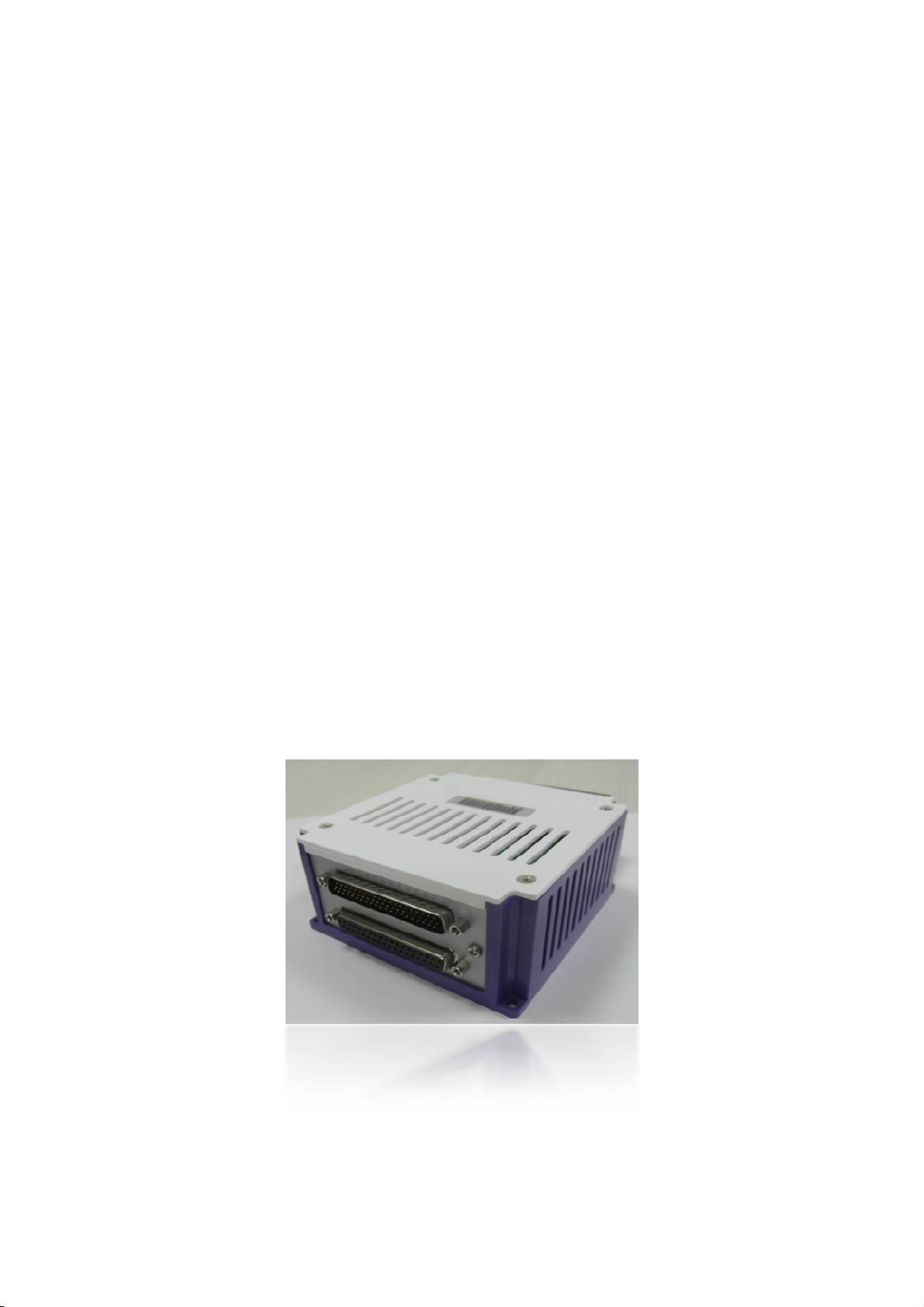
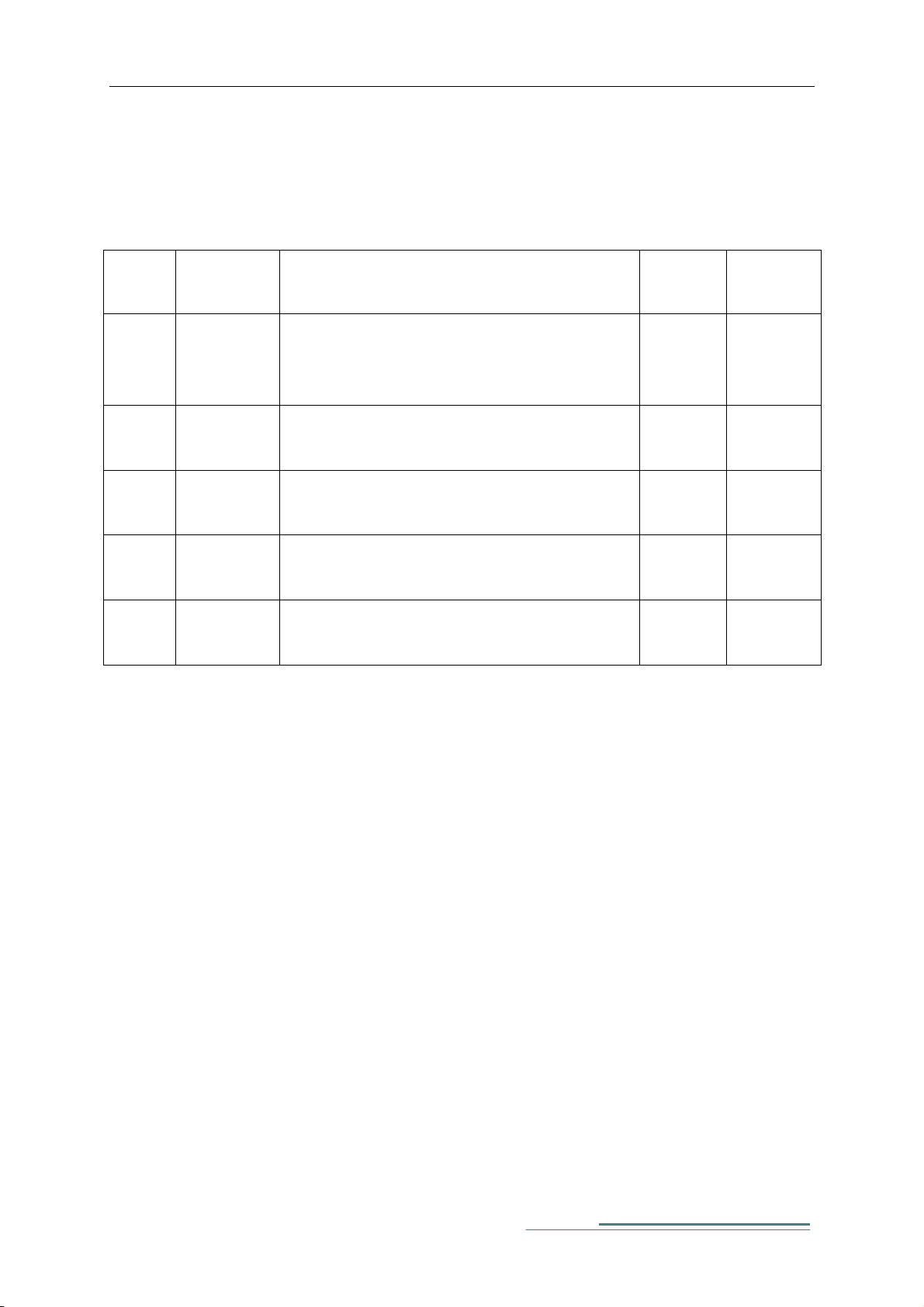
2) Exterior
The picture is of the S-DAQ board and case. The front panel of S-DAQ has
power port (24Vdc), power on/off switch, USB memory port, LAN 2Port,
Mini-USB Port, a port for an external antenna. The rear panel houses LED,
FG, DAQ Port, RS-232 Port connections.
Figure 1 S-DAQ Exterior
3
S-DAQ User Manual
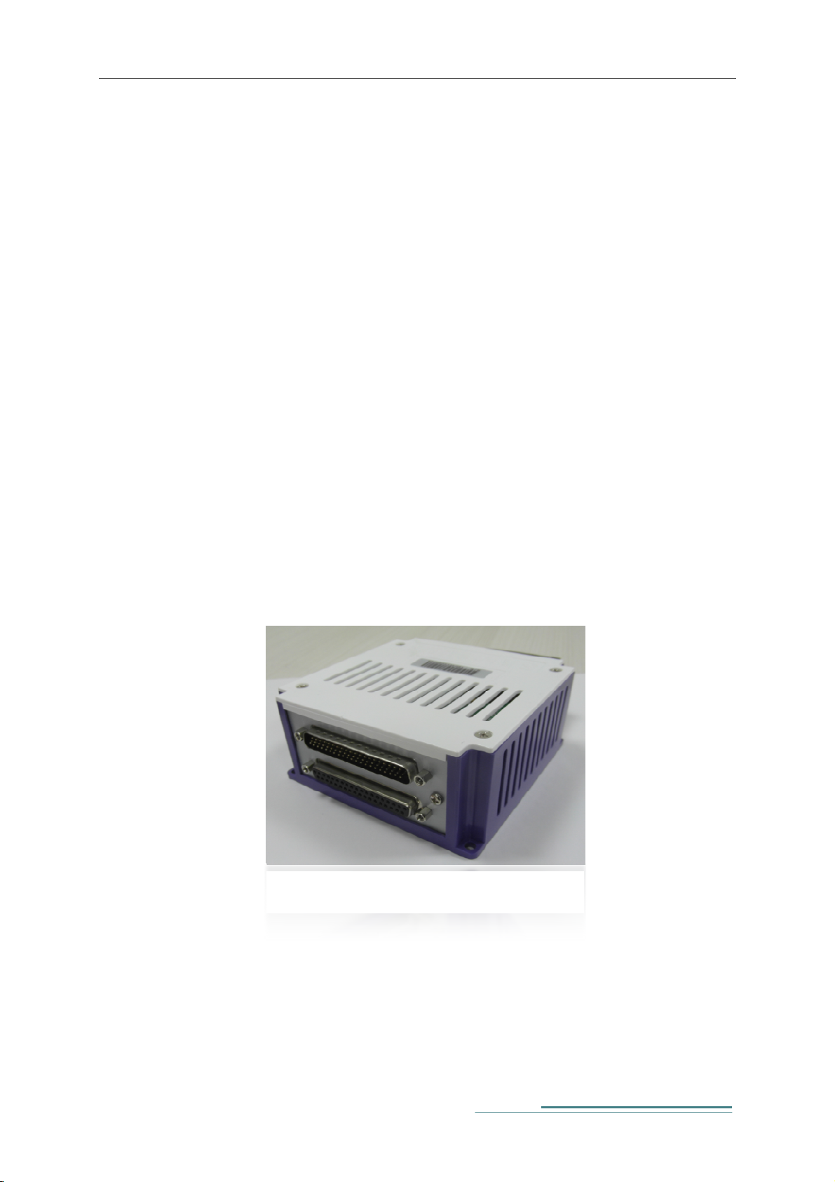
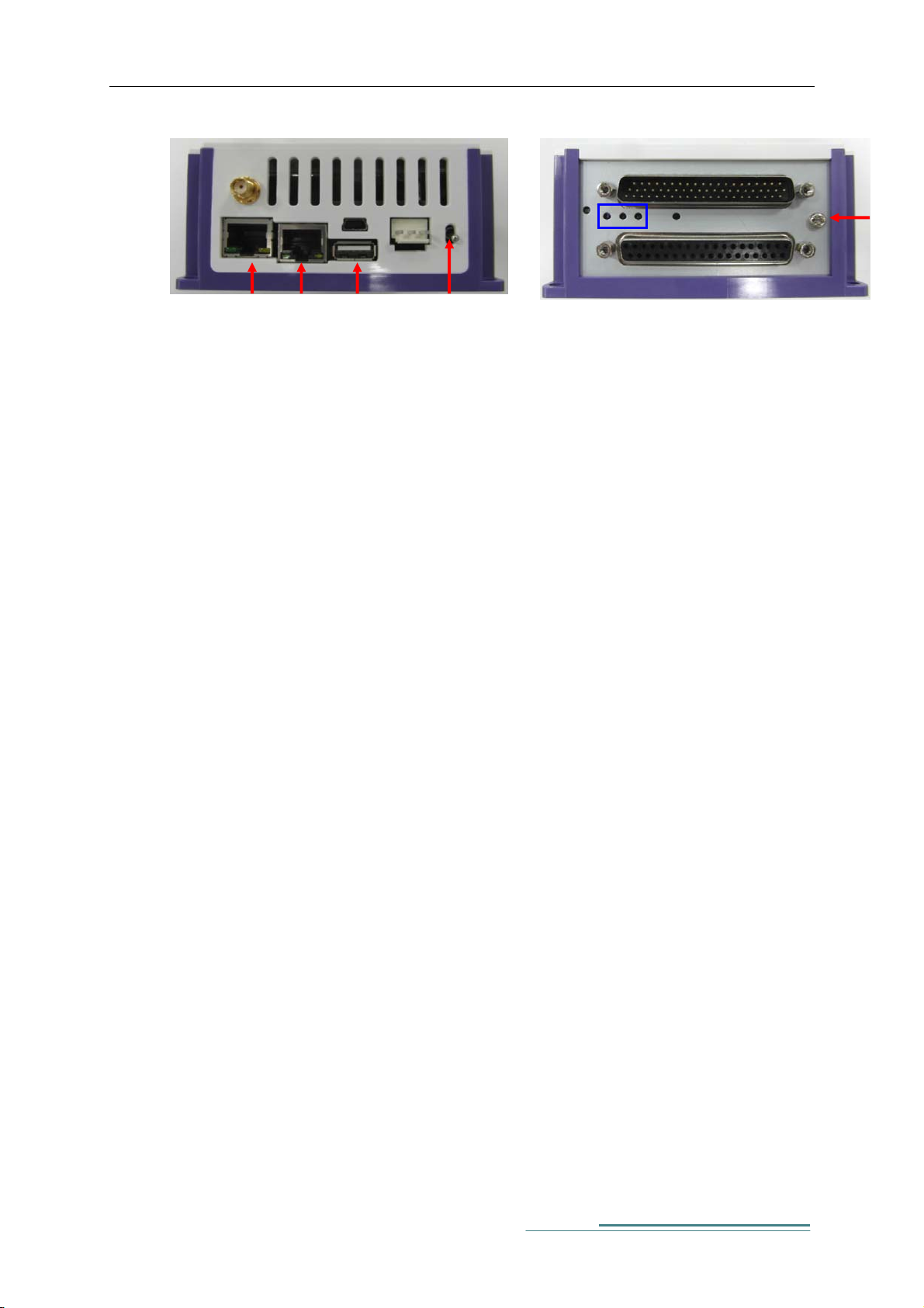
WIFI
Mini USB
LAN0LAN1
USB
ADC : 40Channel
Power
LED(1,2,3
RS-232 : 9Channel
Power
Switch
Figure 2 S-DAQ Front Panel
Figure 3 S-DAQ Rear Panel
A. Power : 24Vdc supply.
B. WIFI : Port for connecting external antenna.
C. LAN0, LAN1 : LAN Port for Ethernet communication with other
devices using TCP/IP.
D. Mini-USB : Developer’s Debug Port.
E. USB : used for S-DAQ FW update.
FG
F. Power Switch : Power On/Off switch.
G. ADC : Receives analogue voltage inputs up to 40 channels.
H. LED(1,2,3) : Status LED
I. RS-232 : for serial communications with other devices (supports up
to 9 channels).
J. FG : Frame Ground for noise reductions. Connects to host
equipment ground.
3) H/W Specifications
A. S-DAQ internal H/W has following characteristics.
i. Freescale i.MX6 Qual Core(1 ㎓ × 4)
ii. Dual Band WIFI, 802.11 a/b/g, Ethernet communications support
iii. FPGA(SPARTAN LX4 ) support
4
S-DAQ User Manual
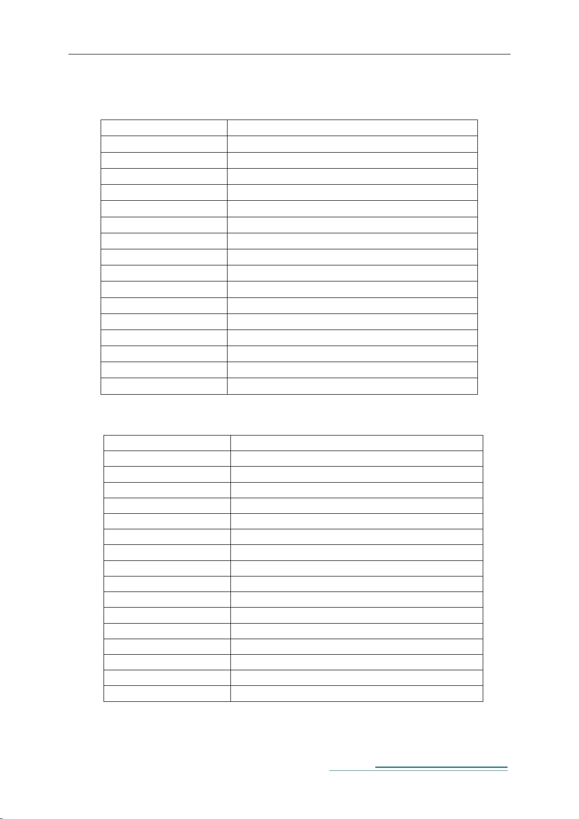
B. DAQ Board H/W Details
ITEM SPECIFICATION
ADC CH SINGLE 40CH, DIFFERENCIAL 20CH 16BIT
INPUT MAX +/- 10V
FILTER 40CH 300KHz LOWPASS FILTER
SAMPLE RATE 40CH 1KSPS (NORMAL), 5CH 64KSPS (MAX)
REFERNCE VOLTAGE 4.096V
ADC CONTROL SPARTAN-6 FPGA SERIES
ISOLATION POWER (1) 2W 5V to 7V DC-DC CONVERTER
ISOLATION POWER (2) 2W 24V to +/- 12V DC-DC CONVERTER
ISOLATION VOLTAGE MAX 6500VRMS 1SEC
ADC I/F SPI 3.3MHz 5CH
CPU I/F SPI 20MHz 1CH
FPGA PROGRAMMING SPI 20MHz 1CH
SUPPLY POWER (1) 3.3V
SUPPLY POWER (2) 5V
SUPPLY POWER (3) 24V
Size 100 x 100 x 16 (mm)
C. CPU Board H/W Details
ITEM SPECIFICATION
ADC CH SINGLE 40CH, DIFFERENCIAL 20CH 16BIT
INPUT MAX +/- 10V
FILTER 40CH 300KHz LOWPASS FILTER
SAMPLE RATE 40CH 1KSPS (NORMAL), 5CH 64KSPS (MAX)
REFERNCE VOLTAGE 4.096V
ADC CONTROL SPARTAN-6 FPGA SERIES
ISOLATION POWER (1) 2W 5V to 7V DC-DC CONVERTER
ISOLATION POWER (2) 2W 24V to +/- 12V DC-DC CONVERTER
ISOLATION VOLTAGE MAX 6500VRMS 1SEC
ADC I/F SPI 3.3MHz 5CH
CPU I/F SPI 20MHz 1CH
FPGA PROGRAMMING SPI 20MHz 1CH
SUPPLY POWER (1) 3.3V
SUPPLY POWER (2) 5V
SUPPLY POWER (3) 24V
Size 100 x 100 x 16 (mm)
5
S-DAQ User Manual
D. RS-232 Board H/W Details
ITEM SPECIFICATION
ADC CH SINGLE 40CH, DIFFERENCIAL 20CH 16BIT
INPUT MAX +/- 10V
FILTER 40CH 300KHz LOWPASS FILTER
SAMPLE RATE 40CH 1KSPS (NORMAL), 5CH 64KSPS (MAX)
REFERNCE VOLTAGE 4.096V
ADC CONTROL SPARTAN-6 FPGA SERIES
ISOLATION POWER (1) 2W 5V to 7V DC-DC CONVERTER
ISOLATION POWER (2) 2W 24V to +/- 12V DC-DC CONVERTER
ISOLATION VOLTAGE MAX 6500VRMS 1SEC
ADC I/F SPI 3.3MHz 5CH
CPU I/F SPI 20MHz 1CH
FPGA PROGRAMMING SPI 20MHz 1CH
SUPPLY POWER (1) 3.3V
SUPPLY POWER (2) 5V
SUPPLY POWER (3) 24V
Size 100 x 100 x 16 (mm)
3. How to Install and Use
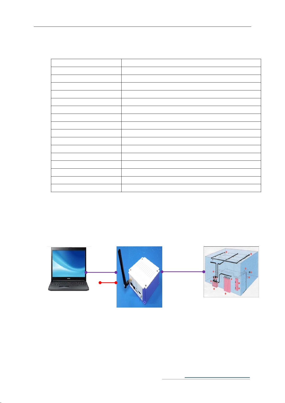
1) S-DAQ Installations
Data PC(Host)
※ Data PC
1. 6GB RAM↑
2. HDD : 1TB↑
Ethernet
24Vdc
※ DAQ Channel
- Single Signal : 40Channel
- Differential Signal :
S-
20Channel
40Ch/Single
※ Connect Component
Analog Output
Ex. Servo Pack Analog Out
(RPM, Torque)
Equipment
6

S-DAQ User Manual
2) S-DAQ Connection Check
A. Change IP Address for Data PC to 192.168.0.5.
B. Power on and confirm LED2 is blinking green.
Blinking
C. Do a ping test to S-DAQ from Data PC to confirm connection.
7

S-DAQ User Manual
3) S-DAQ Pin Map
8

S-DAQ User Manual
4. HW Specifications
i
DAQ : Stands for Data Acquisition. General terminology for measurement of analog input/output,
digital input/output and digital counter/timer.
ii
RS-232 : Serial type communication interface between PC and devices such as sound coupler and
modem.
9

Federal Communication Commission Interference
Statement
This equipment has been tested and found to comply with the limits for a Class B
digital device, pursuant to Part 15 of the FCC Rules. These limits are designed to
provide reasonable protection against harmful interference in a residential
installation.
This equipment generate, uses and can radiate radio frequency energy and, if not
installed and used in accordance with the instructions, may cause harmful
interference to radio communications. However, there is no guarantee that
interference will not occur in a particular installation.
If this equipment does cause harmful interference to radio or television reception
which can be determined by turning the equipment off and on, the user is
encouraged to try to correct the interference by one or more of the following
measures.
- Reorient or relocate the receiving antenna.
- Increase the separation between the equipment and receiver.
- Connect the equipment into an outlet on a circuit different from that
to which the receiver is connected.
- Consult the dealer or an experienced radio, TV technical for help.
- Only shielded interface cable should be used.
Finally, any changes or modifications to the equipment by the user not expressly
approved by the grantee or manufacturer could void the users authority to operate
such equipment.

This device complies with Part 15 of the FCC Rules. Operation is subject to the
following two conditions: (1) this dev ice may not cause harmful interference, and
(2) this device must accept any interference received, including interference that
may cause undesired operation
Caution : Any changes or modifications in construction of this dev ice which are not
expressly approved by the party responsible for compliance could void the user's
authority to operate the equipment.
This device is operation in 5.15 – 5.25 GHz frequency range, then restricted in
indoor use only.
RF exposure warning
This equipment must be installed and operated in accordance with provided
instructions and the antenna(s) used for this transmitter must be installed to
provide a separation distance of at least 20 cm from all persons and must not be
co-located or operating in conjunction with any other antenna or transmitter.
End-users and installers must be provide with antenna installation instructions and
transmitter operating conditions for satisfying RF exposure compliance.
 Loading...