

Samsung SR-61KTC, SR-65NMC, SR-69NMC, SR-65KTC, SR-61NMC Service Manual
REFRIGERATOR CONTENTS
1. Product Specifications 1
2. Safety Warning & Caution 2
3. Electrical part specifications & standard 4
4. Electric diagram 6
5. Air Circulation route 7
6. Function & Vsing method 8
7. Temperature control & other Functions 11
8. Circuit Operating theory 21
9. Failure diagnosis & repairment 36
10. Dissembie & Assemble drowing and part LIST 53
11. Disassemble & Assemble Method 88
12. Packing 84
13. Main componets specification 86
Model: SR-61KTC/SR-61NMC
SR-65KTC/SR-65NMC
SR-69NMC
ITEM.
MODEL NAME
NET DIMENSION
NET WEIGHT
ELECTRIC HEATING EQUIPMENT
POWER
- 2-
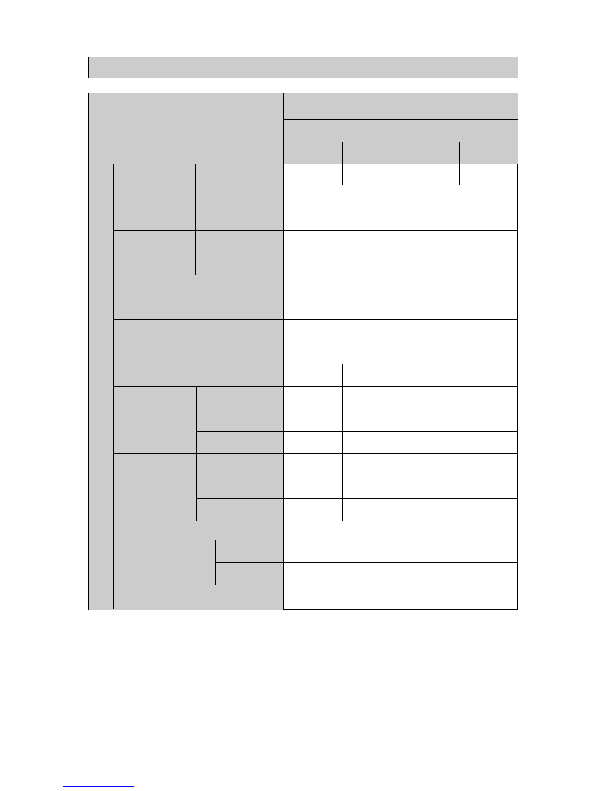
1. Product specifications.
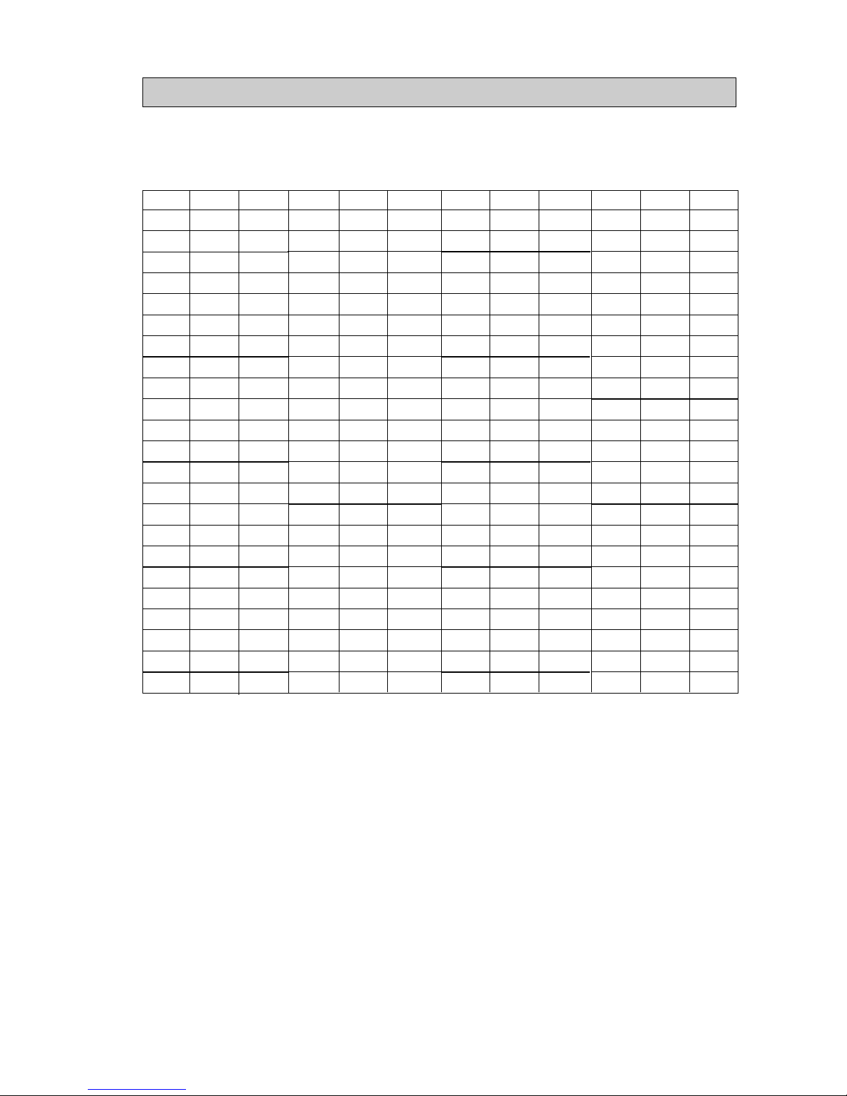
●Classification by Capacity
NET
CAPACITY
TOTAL
FREEZER
REFRIGERATOR
STANDARD
510 MODEL
550 MODEL
590 MODEL
SR69-NMC
SR-61KTC
SR-61MNC
SR-65KTC
SR-65NMC
514LT
153LT
361LT
554LT
165LT
389LT
589LT
165LT
424LT
840*761.5*1755.5
840*761.5*1760.5
840*761.5*1810.5
840*761.5*1854.5
96 KG
97 KG
98 KG
388W
378W
388W
378W
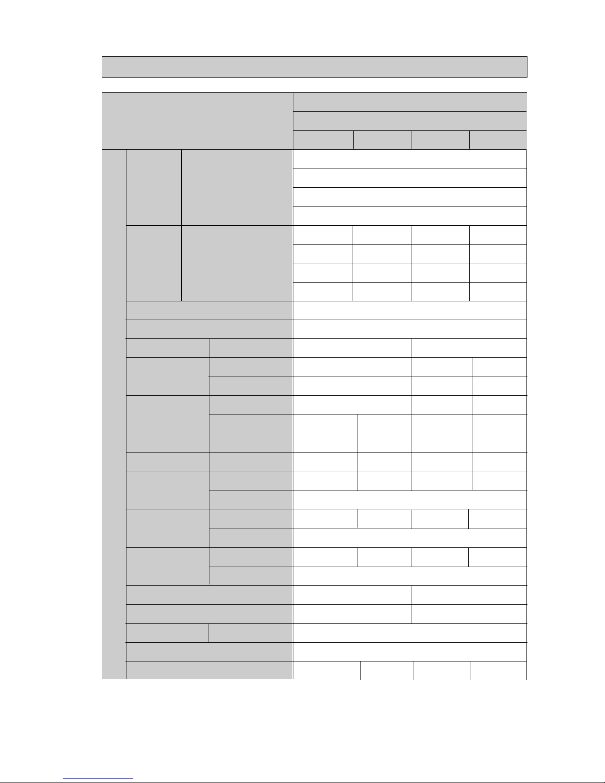
●Classification by Electric power
ITEM.
MODEL NAME
REGULAR FREQUENCY
REGULAR VOLTAGE
ELECTRIC MOTOR REGULAR POWER
SORT OF REFRIGERATOR
COOLING MASS
COOLING MASS SEALED QUANTITY
FREEZER PERFORMANCE
STANDARD
SR-61KTC, 65KTC
SR-61NMC, 65NMC, 69NMC
AC127V / 60Hz
60Hz
AC 127V
AC127V / 60Hz
60Hz
AC 127V
OCCASSIONAL COOLING TYPE REFRIGERATOR
HFC-134α
150 G
4 STAR
AC220V / 50~60HZ
50~60Hz
AC 220V
AC240V / 50HZ
50Hz
AC 240V
AC220V / 50~60HZ
50~60Hz
AC 220V
AC240V / 50HZ
50Hz
AC 240V
- 3-
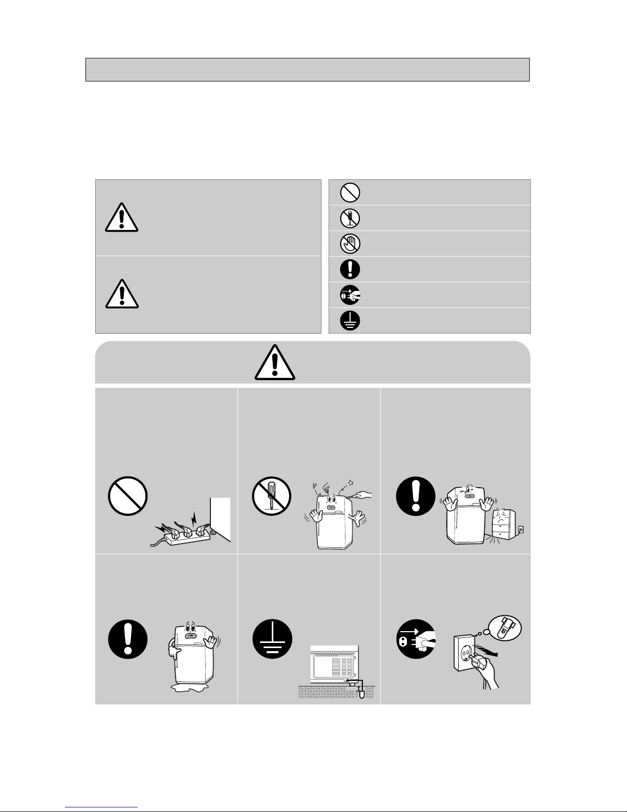
2.Safety precautions and warnings
xRead all instructions before using this product and keep to the instructions
in order to prevent danger or property damage.
25cm
Warning
W arning
Caution
Description of symbolsWarning/Caution
Indicates that a
danger of death
or serious injury
exists.
Indicates that a risk
of personal injury
or material damage
exists.
IN DICATES PROHIBITION
DO NOT DISASSEMBLE
DO NOT CONTANT
ADHERE THE INSTRUCTION STRICTLY
ONPLUP FROM THE ELECTRICAL
AVOLD
EARTH THE APPLIANCE TO AVOID THE
RISK OF AN ELECTRIC SHOCC
Do not insert the power cables.
●
May cause abnormal
generation of heat or fire.
Do not disassemble to
repair or alter.
●
It may cause fire or abnormal
operation which leads to injury.
Do not bend the power cable with
excessive force or do not have the
power cord pressed by heavy article.
●
May cause fire.
Check the operating environment.
●
Deterioration of electric parts insulation
may cause electric shock or fire.
Make sure of the earth.
●
If power doesn’t ground, it will
cause breakdown and electric shock.
Pull the power plug out to exchange
the interior lampof the refrigerator.
●
It may cause electric shock.
Prohibition
Do not
disassemble
Earth
Unplug
- 4-
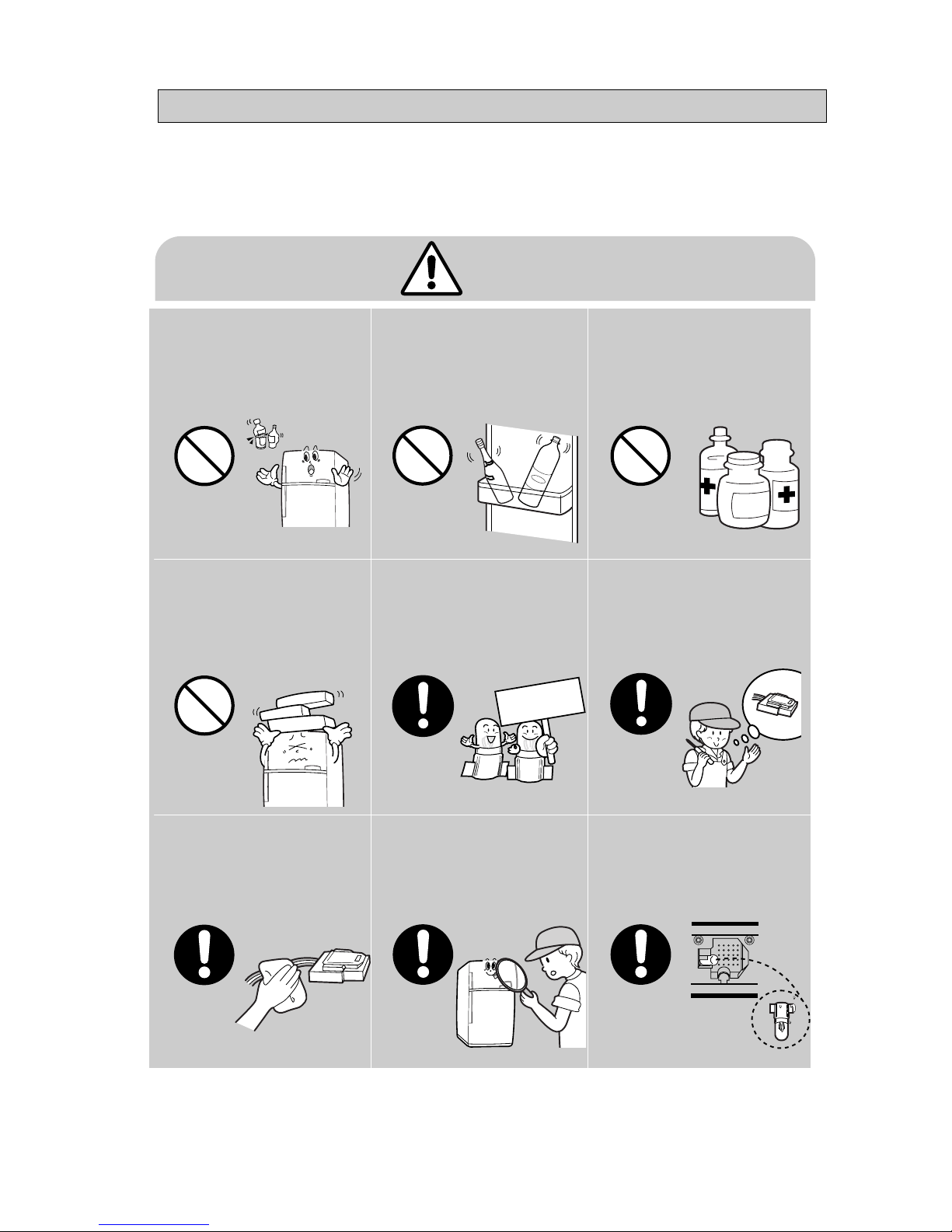
Caution
Do not put bottles or kinds of
glass in the freezer.
●
Freezing of the contents may inflict a
wound.
Do not store narrow and lengthy
bottles or foods in a small multipurpose room.
●
It may hurt you when refrigerator door
open and close.
Do not store pharmaceutical
products, scientific materials,
etc., in the refrigerator.
●
The products which temperature control
should not be stored in the refrigerator.
Do not store articles on the
Refrigeration.
●
Opening or closing the door may
cause things to fall down, wihch
may inflict a wound.
When replacing electric
comporents, be sure to use rates
comporents.
●
Check the model, rated voltage, rated
current, operating temperature etc. of
the component.
On repair, make sure that the wires
such as harness are tightly
bundled.
●
Tghtly bundle wires in order not
to be detached by the external
force and to be wetted.
On repair, remove completely dust or
other things of housing parts,
harness parts, and check parts.
●
Cleaning may prevent the possible fire by
tracking or short.
After repair, check the assembled
state of components.
●
It must be in the same assembled state
when compared with the state before
disassembly.
Check the electrical parts for the
trace of moisture.
●
When the trace of moisture penetration is
detected, replace the patt or try insulation
tapping.
Prohibition
Prohibition
Prohibition
Prohibition
Reted
components
RSCR
Freol α-15(ESTER)
SPLIT FIN TYPE
FORCED AND NATUAL CONUECTION TYPE
MOLECULAR SIEVE XH-9
0.82X2500 4.26Kg/cm
2
HFC-134a
- 5-
3. ELECTRIC PARTS STANDARD
ITEM
STANDARD
DEFROST
TEMPERA TURE
REFRIGERA TION PAR TS
COMPRESSOR
COOLER
MODEL
STARTING TYPE
OIL CHARGE
FREEZER
REFRIIGERATOR
4hours±10minute
10minute±2minute
CONDENSER
DRYER
CAPILLARY TUBE
REFRIGERANT
FREEZER
REFRIGERATOR
HIGH
MID
LOW
HIGH
MID
LOW
FIRST CYCLE
PAUSE TIME
ON(℃)
-21℃
-18℃
-15℃
-0.5℃
3.5℃
6.5℃
OFF(℃)
-23℃
-20℃
-17℃
-1.5℃
2.5℃
5.5℃
ON(℃)
-22℃
-18℃
-15℃
-0.5℃
2.5℃
5.5℃
OFF(℃)
-24℃
-20℃
-17℃
-1.5℃
1.5℃
4.5℃
REFRIGERATOR
FREEZER
CYCLE
SR-61/65/69NMC / SR-61/65KTC
DK172C-L2U
110~115V/60Hz
127V/60Hz
220V/50~60Hz
230~240V/50Hz
DK172P-L2U
SK190H-L2U DK190Q-L2U
SPLIT FIN TYPE & TUBE TYPE
SPLIT FIN TYPE
10hours
20hours
- 6-
ITEM
SENSOR
F-SENSOR
R-SENSOR
F-DEF SENSOR
R-DEF SENSOR
DRAIN HEATER
F DEF HEATER
R DEF HEATER
DID HEATER
F DEF FUSE
R DEF FUSE
CONDENSER
STARTING RELAY
O/L-PROTELTOR
SR-61/65/69NMC
SR-61/65/69NMC
SR-61 / 65KTC
SR-61 / 65KTC
SR-61 / 65KTC
F-LAMP
R-LAMP
DID DOOR-S/W SR-61 / 65KTC
DOOR-S/W
Power cord
SR-61/65/69NMC
SR-61/65/69NMC
DC TRANS
F-COOLER FAN MOTOR
R-COOLER FAN MOTOR
CYCLE FAN MOTOR
502 AT
〃
〃
〃
HEATER
250V 0.7A
250V/0.7A
12V, DC - BLDC , SENSORLESS
12V, DC - BLDC , SENSORLESS
12V, DC - BLDC , SENSORLESS
110 / 130V 15W
130V 30W
240V 15W
240V 25W
SR-61/65/69NMC / SR-61/65KTC
110~115V/60Hz
127V/60Hz
220V/50~60Hz
230~240V/50Hz
12㎌ / 250VAC
J531QE100M2002
10Ω±20%(
SURROUNDING TEM
25℃)
250V 10A 72
±4℃
250V 10A 72
±4℃
5㎌ / 350VAC
13W / 110V
235W / 220V
120W / 110V
10W / 110V
13W / 127V
235W / 127V
120W / 127V
10W / 127V
13W / 220V
235W / 220V
120W / 220V
10W / 220V
13W / 240V
235W / 240V
120W / 240V
10W / 240V
69
℃
130
℃
115V 50/60Hz
110V 60Hz
69
℃
125
℃
127V 50/60Hz
127V 60Hz
69
℃
130
℃
220V 50/60Hz
220V 50/60Hz
J531Q34E100M350-2
220Ω±20%
(
SURROUNDING TEM
25℃)
4TM314RHBYY-53
61
℃
130
℃
240V 50/60Hz
240V 50Hz
110V 60Hz
127V 60Hz 220V 50~60Hz 230~240v 50Hz
110V 60Hz
127V 60Hz 220V 50~60Hz 230~240v 50Hz
J531Q35E330M385-2
330Ω±20%
(
SURROUNDING TEM
25℃)
4TM265RHBYY-53
4TM437RHBYY-53
EP-2,127V/7A
SPT-3,125V/7A VCP-2,250V/10A BF-3,250V/10A
OPERATION
MODEL
START
MADEL
ON TEM
OFF TEM
ELECTRIC P AR TS
-7-
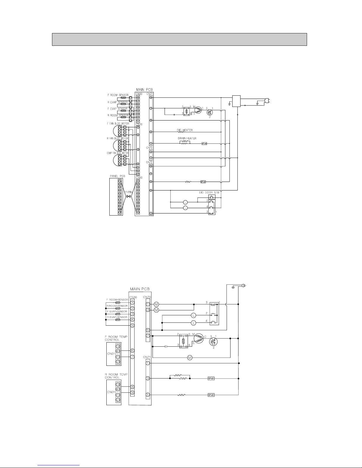
4. Electric diagram
ORG
ORG
YEL
YEL
YEL
BLU
VLT
BLK
BRN
BRN
BRN
GRY
GRY
GRY
GRY
RED
RED
RED
PIK
PIK,BLU
RED
RED
RED
RED
RED
RED
RED
RED
RED
F DEFROST-NEATER
R DEFROST-NEATER
RED
R ERM FUSE
F ERM FUSE
COMP RELAY
COMPRTSSOR COOLER MOTOR
OPERATING CONDENSER
WHT
WHT
WHT
WHT
WHT,BLK
SIBLU
SIBLU
SIBLU
SIBLU
SIBLU
EARTHED
CIRCUIT
FREEZER FAN MOTOR
DOOR SWITCH
FREEZER FAN MOTOR
REFRIGERATOR LAMP
FREEZER LAMP
4-2) SEMI BASIC (SR-61NMC, 65NMC, 69NMC)
4-1. Electronic mode(SR-61KTC,65KTCT)
BLU
BLU
VLT
VLT
VLT
VLTVLT
BLK
BLK
BLK
BLK
BLK
BLK
BLK
EARTHED
CIRCUIT
EARTHED
CIRCUIT
BLK
BLK
BLK
BLK
W / B
W / B
BRN
BRN BRN
BRN
RED
RED
RED
RED
RED
GRN
EMI
FILTER
WHT
GRN
RED
REDRED
RED
F-DEFROST-HEATER
R-DEFROST-HEATER
REFRIGERATOR
FREEZER LAMP
RED
RED
WHT
ORG
ORG
ORG
ORG
PNK
BLU
VLT
GRY
GRY
GRY
GRYGRY
GRY
GRY
GRY
WHT
WHT
WHT
YEL
YEL
YEL
SIBLU
SIBLU
SIBLU
SIBLU
P .T.C RELAY
COMPERESSOR
COMP RELAY
OPERATING
CONDENSER
SIBLU
SIBLU
BLK
BRN
RED
RED
ORG
PNK
PNK
BLU
VLT
GRY
WHT
SIBLU
SIBLU
GRY
F-TEM FUSE
R-TEM FUSE
-8-
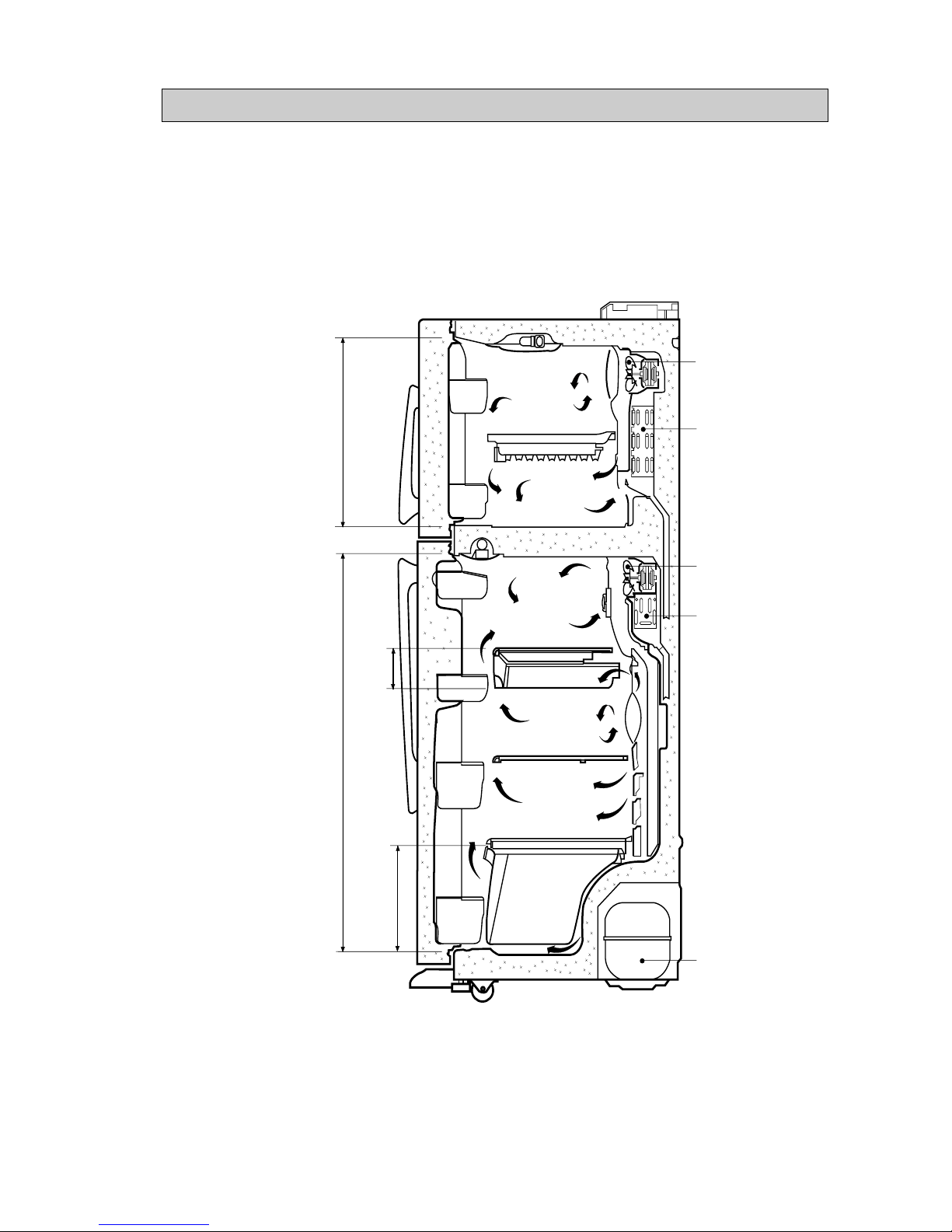
5. Cool Air Circulation
Freezer
Refrigerator
Case of Re
frigerator
Vegetabele
part
Compressor
Cooler of
Refrigerator
Cooling fan of
Refrigerator
Cooler of
Freezer
Cooling fan of
Freezer
-9-
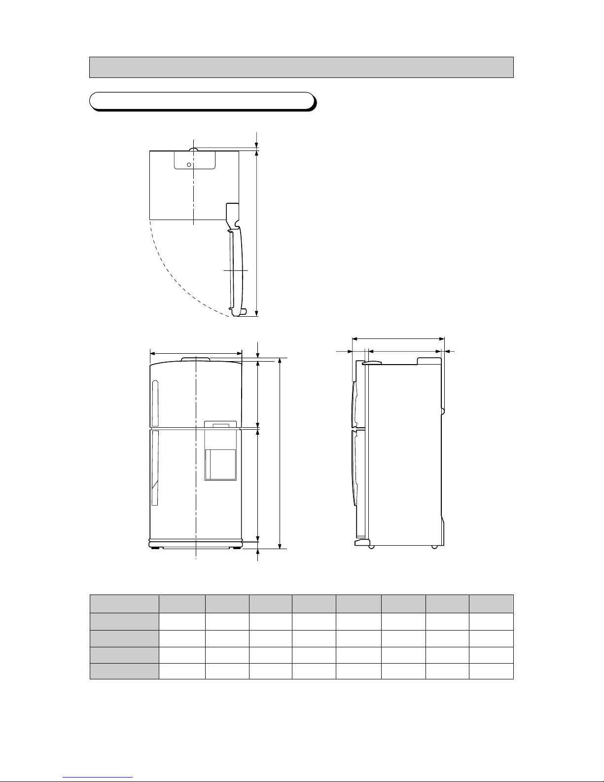
6-1. THE OUTER SIZE
6. FUNCTIONS AND DIRECTIONS
MODEL
SR-61KTC
SR-61NMC
SR-65KTC/NMC
SR-69NMC
A
1066.5
1066.5
1096.5
1140.5
B
580
580
600
600
C
1755.5
1760.5
1810.5
1854.5
D
761.5
761.5
761.5
761.5
E
617.5
617.5
617.5
617.5
F
1479
1479
1479
1479
G
123
123
123
123
F
17
A
C
B
9.5
9
71.5
840
D
EG
11
10
10
-10-
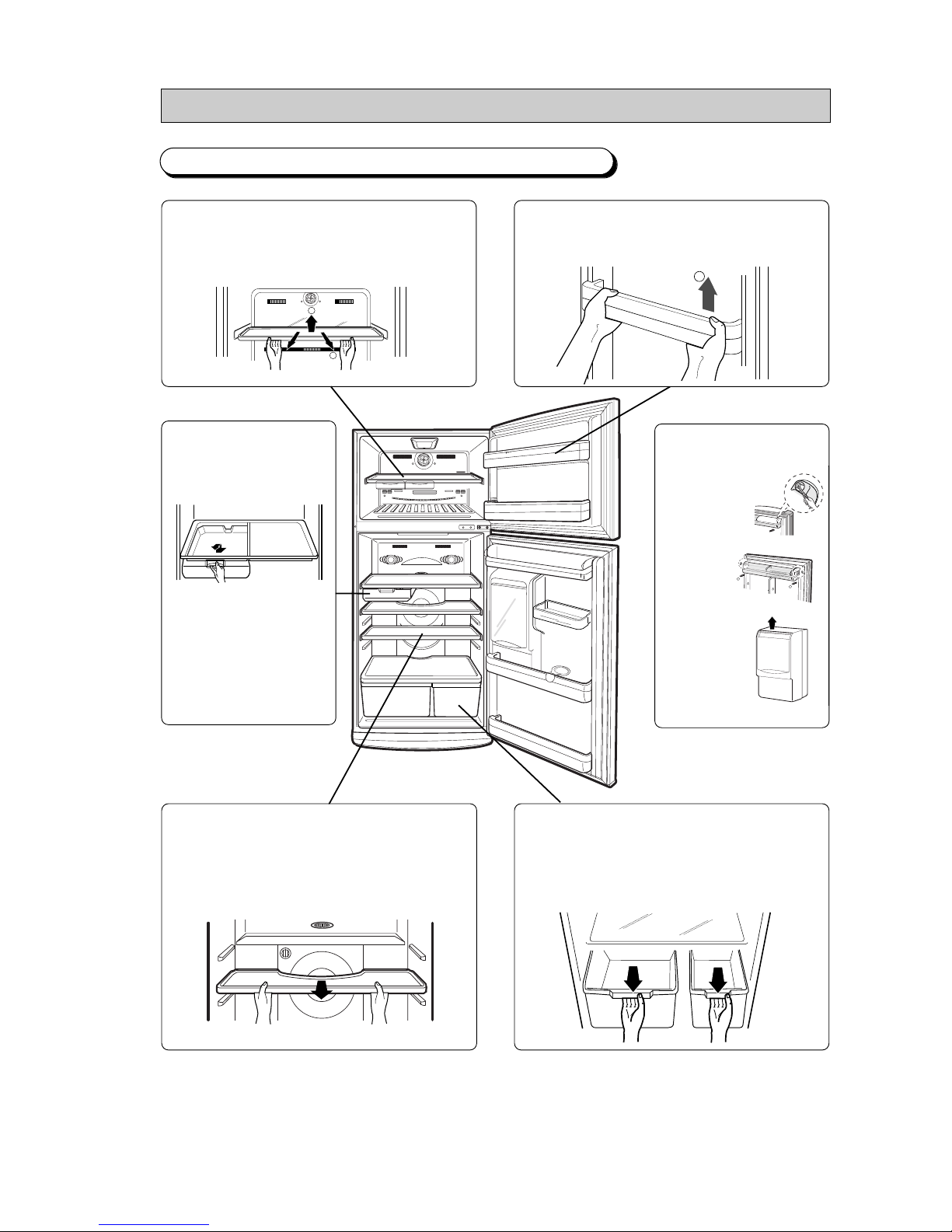
6-2. THE NAME OF EACH PARTS AND DISASSEMBLE METHOD
●
Pull with both hands as showed
●
The height can be adjusted according to the stored bowls.
2
●
Push to direction ②
●
Up the front of shelf to direction ①then pull and
apart to direction②.
2
1
FREEZER SHELF
DOOR GUARD
TEMPERRD GLASS TRAY
CHILLED ROOM SHELF
DID CASE
●
Upthe cover and apart then pull out the vegetable//salad
compartment cover and case at the mid-point and up
and pull to apart.
VEGETABLE/SALAD COVER AND CASE
●
Pull to the arrow direction
then up and apart at the
locking point.
1
2
●
Pull and apart
display part of
door guard.
●
Up and apart
as showed.
-11-
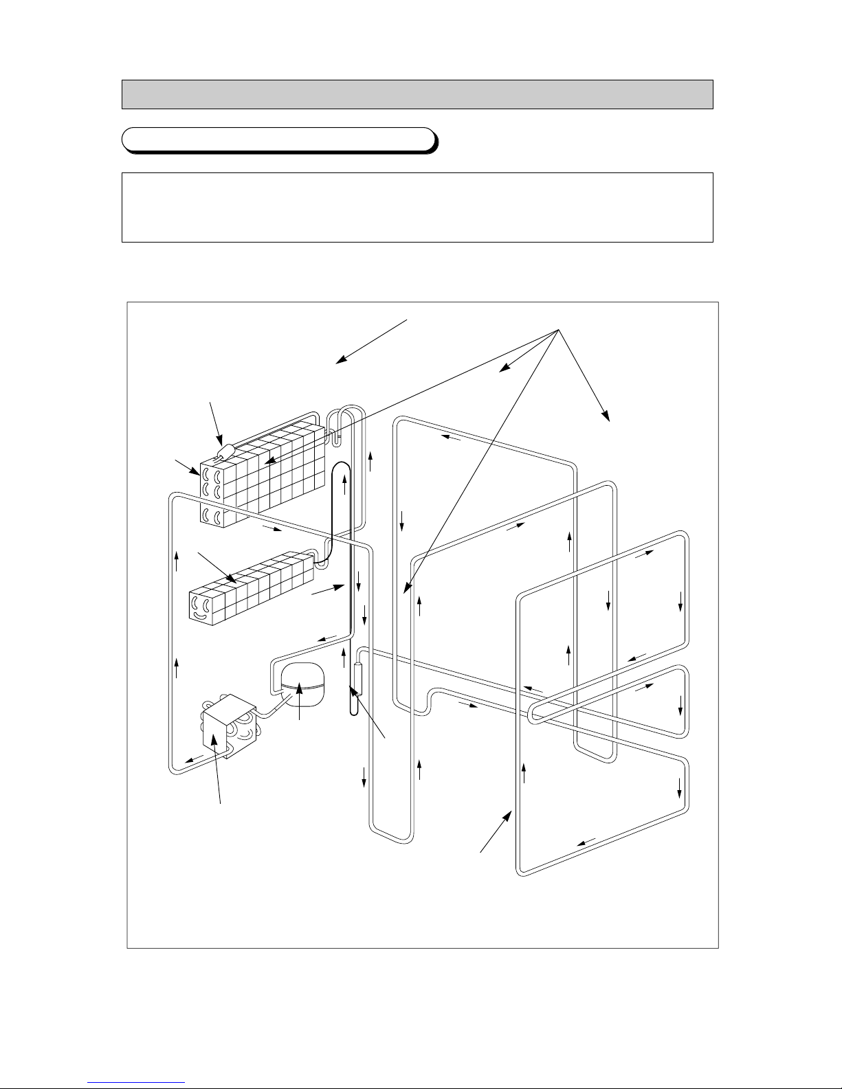
6-3. CYCLE OF FREEZING
COMPRESSOR → SUB CONDENSER → CLUSTER PIPE → HOT PIPE → DRYER → CAPILLARY TUBE
→ EVAPORATOR OF REFRIGERATOR → EVAPORATOR OF FREEZER → ACCUMULATOR →
SUCTION PIPE → COMPRESSOR
ACCUMULATOR
SUCTION PIPE
CLUSTER PIPE
HOT PIPE
DRYER
COMPRESSOR
CAPILLARY
TUBE
SUB CONDENSER
EVAPORATOR OF
REFRIGERATOR
EVAPORATOR OF
FREEZER
-12-
7. TEMPERATURE CONTROL AND THE OTHERS
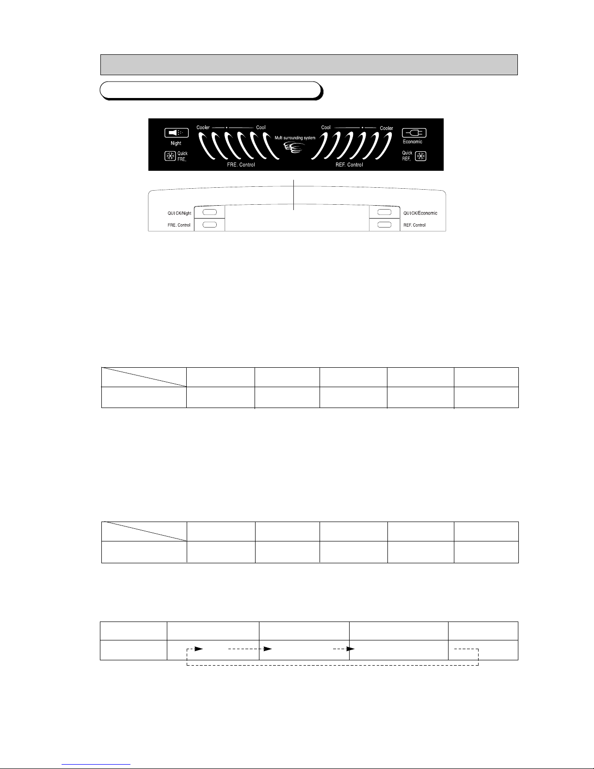
1) Freezer temperatur control
1-1)
It consists of five steps as follows and selected by one button.
MID →MID,HIGH →NIGH →LOW →LOW,MID
1-2)
setting up turn on a light in order by system of freezer cholce button.
( MID →MID,HIGH →NIGH →LOW →LOW,MID →MID...)
1-3) It set up “
MID”
automaticature during power on.
1-4) There is standard temperatically list of each notch part. (1/3H standard)
1-5) When inputting freezer key, display of LED change at once but actual operating start in 10 seconds
2) Refrigerator temperature control
2-1)
It consists of five steps as follows and selected by one button.
MID →MID,HIGH →NIGH →LOW →LOW,MID
2-2)
setting up turn on a light in order by system of freezer cholce button.
( MID →MID,HIGH →NIGH →LOW →LOW,MID →MID...)
2-3) It set up “
MID”
automaticature during power on.
2-4) There is standard temperatically list of each notch part. (1/3H standard)
2-5) When inputting freezer key, display of LED change at once but actual operating start in 10 seconds
3) Ppwer freezering / Regular condition /9in bed)
1) It select just power freezer / Regular condition.
2) If you press power freezing / regular freezing → Power freezing → Regular condition.
3) When first power on, lamp does appear.
TEMPERATURE
ITEM
NOTCH
LOW
-16.0℃
⊙
-17.5℃
MID
-19.0℃
⊙
-20.5℃
HIGH
-22.0℃
CLASSIFICATION
LAMP CHANGE
First POWER ON
OFF
Pressed once
POWER freezing
Pressed twice
Regular condition operating
TEMPERATURE
ITEM
NOTCH
LOW
+6.0℃
⊙
+4.5℃
MID
+3.0℃
⊙
+1.0℃
HIGH
-1.0℃
1. DISPLAY DESIGN
2. Temperature control function
7-1. ELECTRONIC MODE
-13-
3-1) Power freeze function
A. Input power freeze/regular condetion key. When power freeze startes, LED signal change at once.
(Comp and F-fan runs continuously for two and a half hours when quick freeze sekected.)
B. During quick freezing the refrigerator controlled by setted notch.
3-2) Regular condition function
A. Judge the temp. of F/R room, F room is over comp on of “LOW”NOTCH or R room is over comp on of “LOW”NOTCH.
If so regular condition function isn’t performed and LED is OFF below 0.5 seconds.
B. Input the function, judge temp. of F room or R room, F room is less than comp on of “LOW”NOTCH and R room is less than
comp on of “LOW”NOTCH. If so regular condition function is operate and comp F,R-FAN is off without state of operation in recently.
C. When state the operation of regular condition, judge the temp. of F/R room, F room is over comp on of “LOW”NOTCH or R room is
over comp on of “LOW”NOTCH. If son regular condition function is the end and it is returned before.
4) Power refrigerator/Power saving function
1) Select power refrigerator/power saving button
2) Press POWER/SAVING BUTTON at once. And it is selected “OFF”“Power refrigerator”“Saving operation”.
3) Initial power on isn’t signal.
4-1) Power refrigerator function
A. Input power refrigerator/saving key. When power refrigerator started, LED signal change at once.
(Comp. and R-fan runs until the temperature of refrigerator reaches -4℃ when quick refrigeration selected.)
B. During power refrigerator the freezing controlled by setted notch.
4-2) Saving operation function.
A. Input saving operation button, F/R room temp. operate 0.8℃ rising. (When situation about NOTCH, rised 0.8℃)
B. When input power freezer or power refrigerator, saving function stop to the end of power function and saving operation is
performed after the end of power function.
※ When power freeze and refrigeration selected at the same time
- Each function applied at the same time Power freeze runs Comp. and F-fan for two and half hours and power refrigeration runs
Comp. and R-fan for -4℃ and power refrigeration runs.
3. Alarming
1) Button touch(“Ding-Dong”sound)
1-1) Everytime the button pushed, the input confirmation, “Ding-Dong”sound.
1-2) Not sounds, if two keys are pushed at the same time or wrongly handled
2) Door-Open Warning
2-1) Two minutes after door opened, alarming sounds.
2-2) If door opened continuously, ten times of alarming sounds with one minute cycle.
2-3) Alarming stopped just after door closed.
CLASSIFICATION
CHANGE OF SIGNAL LAMP
INITIAL POWER ON
OFF
PRESS ONE
POWER REFRIGERATOR
PRESS T ONE
SAVING OPERATION NOTES
NOTES

-14-
3) Forced operating and defrosting (“Beep”sound)
3-1) If forced function selected the “Beep”sounds.
3-2) Alarming sounds until the forced operating canceled by automatically(24Hr) or manualy.
3-3) Alarming sounds until the forced defrosting canceled by automatiically(24Hr) or manualy.
4) Defrosting
1-1) From the first power on, defrosting started after 4 hours of total Comp on time.
1-2) After that defrosting cycle can be varied from 6 hours to 24 hours.(Comp on time)
5) Testing
◆ Testing is for PCB, product, function and service.
◆ After testing, turn the power on to start self diagmosis.
1) Fored operating
1-1) As the button on PCB pushed once, Comp starts immediately.
1-2) If fored operating selected the notch of freezer and refrigerator fixed to “HIGH”and “MID-HIGH”. Then comp and
F-fan is controlled to pull down and R-fan is controlled to “MID-HIGH”notch.
1-3) Pull-down maintained just for 24 hours during forced operating, after that automatically defrost freezer and refrigerator
and then stares nomal operating.
1-4) Turn the power off or select test cancel mode to cancel the forced operating.
1-5) Alarming (0.25 secon/0.75 sec off) continues until the forced operating finished. It continues without any relations
to alarming key selection or cancel.
2) Forced defrosting
2-1) Push the test button one more time to run the forced defrosting of refrigerator.
2-2) One more push in the above status will run defrosting of freeaer and refrigerator simult a neously.
2-3) Forced operating cancelled automatically by starting forced defrosting and return to normal operating
after campletion of defrosting.
3) Test cancel mode
3-1) One more push in the status of forced defrosting of F/R wiill run normal operating.
3-2) Alarming stopped in the test cancel mode.
4). Initial function of first POWER ON.
1) If power is impressed, it begins to make a self diagnosis and light all LED for 2 second if normal condition is confirmed.
2) After first self diagnosis find unstable sensor among temp. sensor. And LED is on and off 5 second periods.
3) During 2 second turn on all LED. AND F/R LED display “MID-MID”
4) Early state R-EVA and F-EVA sensor is all below 15℃.
And R defrosting HEATER and F defrosting HEATER is perform per 0.5 second turn on.
5) After early state R-EVA sensor temp. or F-EVA sensor is over 15℃ and F/R defrosting is end per 3 second,
COMP and F-FAN, R-FAN is turn on per 0.5 second and operated per 5 minutes without temp. condition.
6) Input TEST S/W among 4) and 5) movemen 5 it is the end and perform TEST function.
-15-
1) SELF DIAGNOSIS AT FIRST POWER ON
1-1) As the power applied to the refrigerator first time, all dispays show operating and run the self diagnosis.
1-2) If no problem foundes, display returns to normal mode
1-3) If probiem foundes, on and off the related display lamp and start alarming.
1-4) Lamp displayed until the problem solved or seif diagnosis cancelled.
1-5) After problem solved the display mode return to nomal.
1-6) After refrigerator repaired, sure to power off and on to run self diagnosis.
1-7) Refer to belows for problem and related displays.
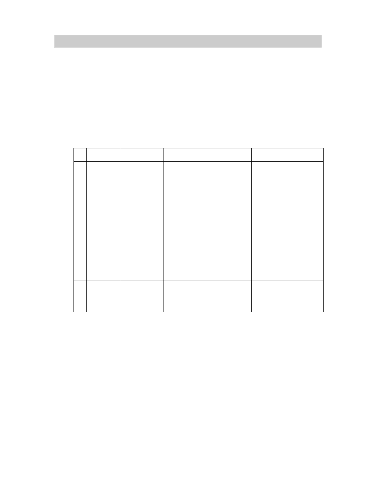
NO
1
2
3
4
5
SYMPTOM
Refrigerator sensor houslng disconnection
Faulty connection
Wire open or short
Faulty sensor
Refrigerator defrost sensor houslng
disconnection
Faulty connection
Wire open or short
Faulty sensor
Room-Temp senser LEAD disconnection
Faulty connection(PCB MAIN)
Wire open or short
Faulty sensor
Freezer defrost sensor houslng
disconnection
Faulty connection
Wire open or short
Faulty sensor
Freezer defrost sensor houslng
disconnection
Faulty connection
Wire open or short
Faulty sensor
REMARK
R-SENSOR temperature is over
+50℃ or below -50℃
RD-SENSOR temperature is over
+50℃ or below -50℃
Room-Temp sensor temperature
is over +50℃ or below -50℃
ZF-SENSOR temperature is over
+50℃ or below -50℃
FD-SENSOR temperature is over
+50℃ or below -50℃
ITEM
R-SENSOR
RD-SENSOR
ROOM-TEMP
SENSOR
F-SENSOR
FD-SENSOR
DISPLAY LED
Refrigerator
“LOW”
Refrigerator“MID”
Freezer“LoW”
Freezer“LOW,MID”
Freezer“MID”
( SELF-DIAGNOSIS DISPLAY TABLE) )
5. SELF DIAGNOSIS
-16-
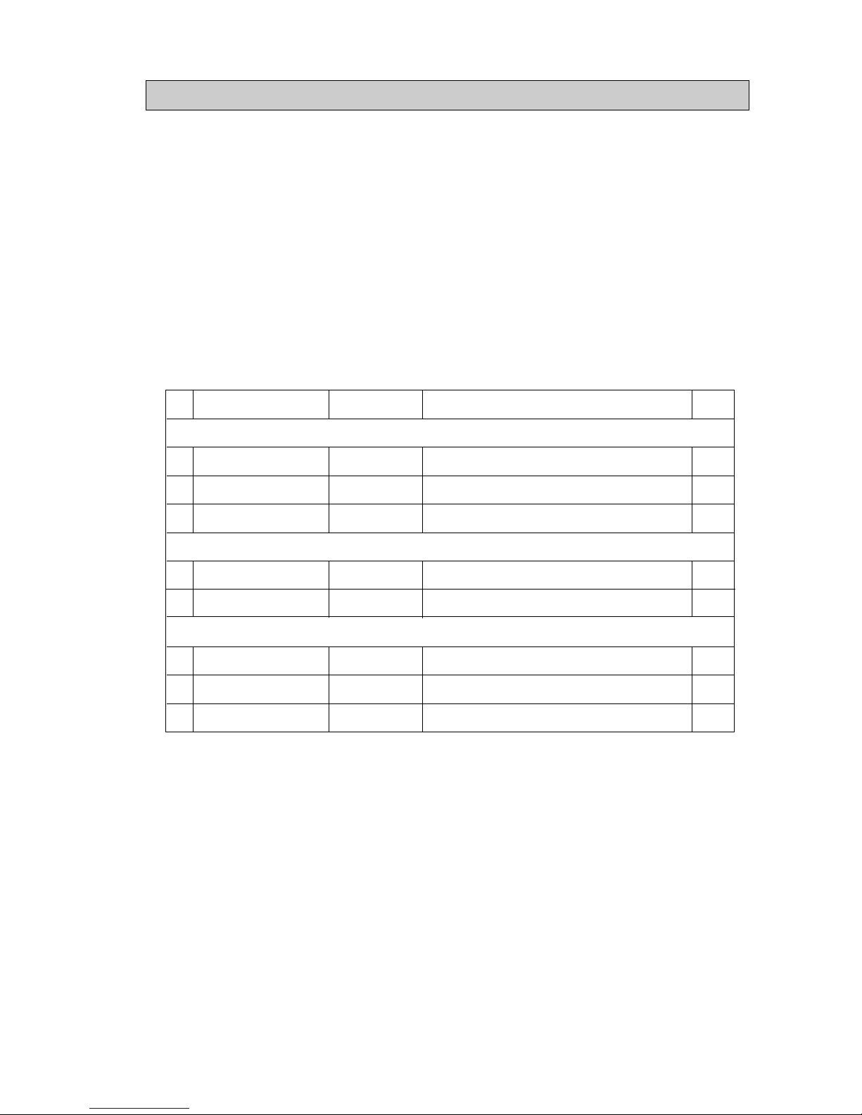
NO
1
2
3
4
5
6
7
8
MODE DISPLAY
REFRIGERATOR SUBORDINATE
FREEZER SUBORDINATE
(LOAD STATUS DISPIAY TABLE)
1) Press power freezing / regular conditing and power refrigerating / power saving key for five seconds then
press temperature control key in the refrigerator after temperature display lamps on and off three times
2) This mode shows which lamps is being sourced signal from MICOM currently. This doesn’t mean the load is
operate due to the open wire or relay missing though the display shows the compressor operating.
3) Load status display return to normal mode after sixty seconds.
4) Follows are load status and related dispay.
6. LOAD STATUS DISPLAY
ITEM
COMP
F-FAN
FREEZER DEFROST HEATER
R-FAN, S-FAN
REFRIGERATOR DEFROST HEATER
INITIAL MODE
OVERLOAD
LOW TEMP MODE
DISPLAY LED
FREEZER ”LOW”
FREEZER ”LOW,MID”
FREEZER ”MID”
REFRIGERATOR ”LOW”
REFRIGERATOR ”MID”
POWER FREEZER
POWER REFRGERATOR
POWER SAVING
DISPLAY
RELEVANT LED ON DURING COMPRESSOR OPERATION
RELEVANT LED ON DURING F-FAN OPERATION
RELEVANT LED ON DURING FREEZER DEFROST HEATER ON.
RELEVANT LED ON DURING S-FAN AND F-FAN OPERATION
RELEVANT LED ON DURING REFRIGERATOR DEFROST
RELEVANT LED ON QITH INITIAL POWER INPUT.
RELEVANT LED ON QHEN ROOM-TEMP. IS OVER 35℃
RELEVANT LED ON QHEN ROOM-TEMP. IS BELOW 15℃
-17-
7. operating of fan motor
8. OPTION TABLE
1) FAN MOTORoperates BLDC MOTOR by dc power.
2) After first starting power, it operates “HIGH”rpm to off dot of fan and then operates “LOW”rpm
3) if binding motor or not sensing regular freguency of motor to pcb, motor will stop operating.
(After stopping, reoerating start in 10 seconds.)
※ F, R, C-FAN operate equal.
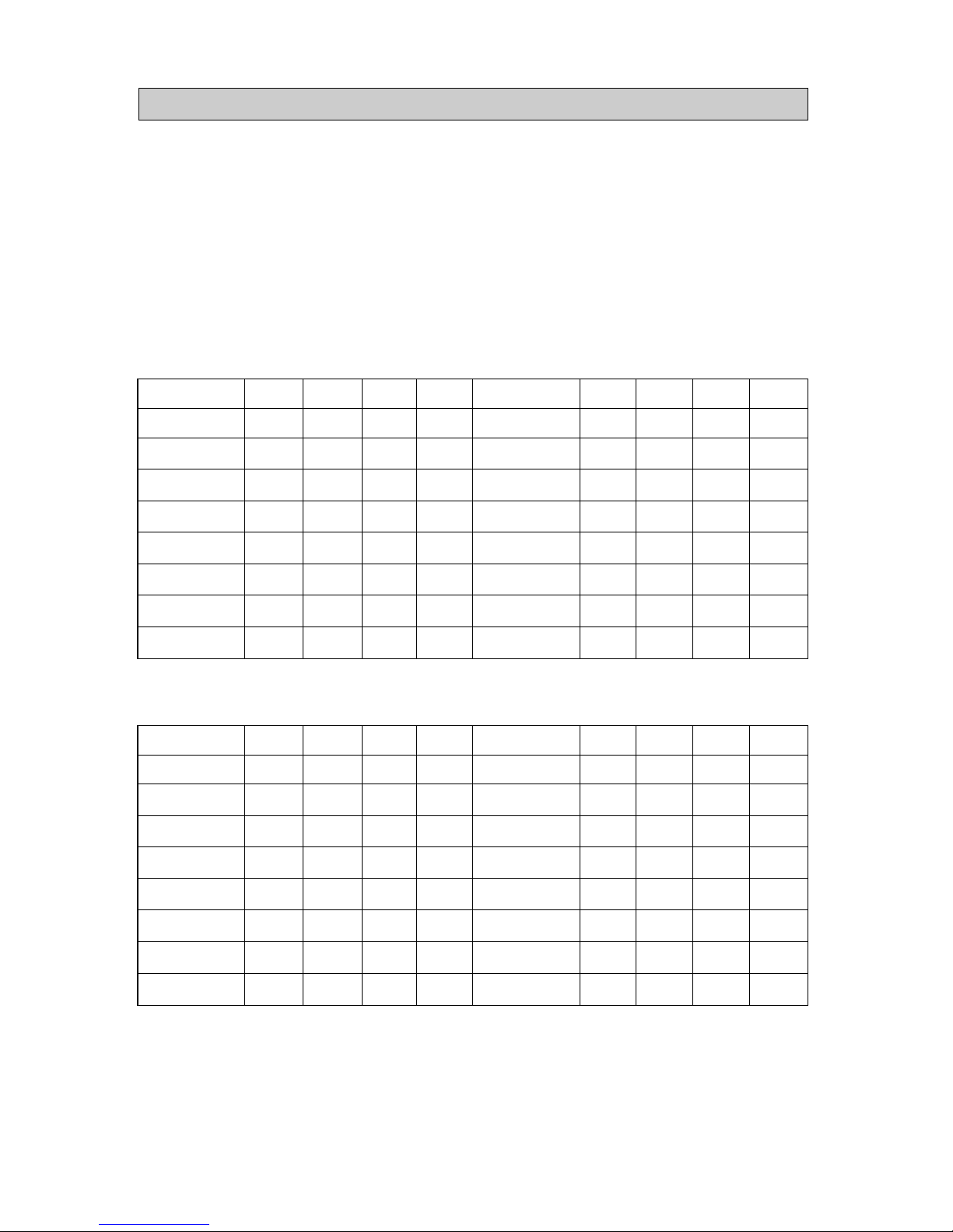
1) Temperature change TABLE of Freezer ( ● : Pertinent DIODE )
SHIFT
STANDARD TEMPERATURE
-0.5
-1.0
-1.5
-2.0
-2.5
-3.0
-3.5
SHIFT
+0.5
+1.0
+1.5
+2.0
+2.5
+3.0
+3.5
+4.0
4
4
●
●
●
●
●
●
●
●
3
●
●
●
●
3
●
●
●
●
2
●
●
●
●
2
●
●
●
●
1
●
●
●
●
1
●
●
●
●
2 ) Temperature change TABLE of refrigerator ( ● : Pertinent DIODE )
SHIFT
STANDARD TEMPERATURE
-0.5
-1.0
-1.5
-2.0
-2.5
-3.0
-3.5
SHIFT
+0.5
+1.0
+1.5
+2.0
+2.5
+3.0
+3.5
+4.0
8
8
●
●
●
●
●
●
●
●
7
●
●
●
●
7
●
●
●
●
6
●
●
●
●
6
●
●
●
●
5
●
●
●
●
5
●
●
●
●
-18-
※ Personal Informatin
Micomport Voltage and Resisting force of sensor by Temperature.
TEMPERATURE (℃)
-42
-41
-40
-39
-38
-37
-36
-35
-34
-33
-32
-31
-30
-29
-28
-27
-26
-25
-24
-23
-22
-21
-20
RESISTANCE
98870
93700
88850
84150
79800
75670
71800
68150
64710
61480
58430
55550
52840
50230
47770
45450
43260
41190
39240
37390
35650
33990
32430
VOLTAGE (V)
4.541
4.518
4.494
4.469
4.443
4.416
4.389
4.360
4.331
4.301
4.269
4.237
4.204
4.170
4.134
4.098
4.061
4.023
3.985
3.945
3.905
3.863
3.822
TEMPERATURE (℃)
-19
-18
-17
-16
-15
-14
-13
-12
-11
-10
-9
-8
-7
-6
-5
-4
-3
-2
-1
0
1
2
3
RESISTANCE
30920
29500
28140
26870
25650
24510
23420
22390
21410
20480
19580
18730
17920
17160
16430
15740
15080
14450
13860
13290
12740
12220
11720
VOLTAGE (V)
3.778
3.734
3.689
3.644
3.597
3.551
3.504
3.456
3.408
3.360
3.310
3.260
3.209
3.159
3.108
3.057
3.006
2.955
2.904
2.853
2.801
2.750
2.698
TEMPERATURE (℃)
4
5
6
7
8
9
10
11
12
13
14
15
16
17
18
19
20
21
22
23
24
25
26
RESISTANCE
11250
10800
10370
9959
9569
9195
8839
8494
8166
7852
7552
7266
6992
6731
6481
6242
6013
5792
5581
5379
5185
5000
4821
VOLTAGE (V)
2.647
2.596
2.545
2.495
2.445
2.395
2.346
2.296
2.248
2.199
2.151
2.104
2.057
2.012
1.966
1.922
1.878
1.834
1.791
1.749
1.707
1.667
1.626
TEMPERATURE(℃)
27
28
29
30
31
32
33
34
35
36
37
38
39
40
41
42
43
44
45
46
47
48
49
RESISTANCE
4650
4487
4329
4179
4033
3894
3760
3631
3508
3390
3276
3167
3062
2962
2864
2770
2680
2593
2510
2429
2352
2278
2206
VOLTAGE (V)
1.587
1.549
1.511
1.474
1.437
1.104
1.366
1.322
1.298
1.266
1.234
1.203
1.172
1.143
1.113
1.085
1.057
1.030
1.003
0.977
0.952
0.928
0.904
-19-
7-2, SEMI ELECTRONIC MODE
A. Temperature control part design
B. Temperature control function
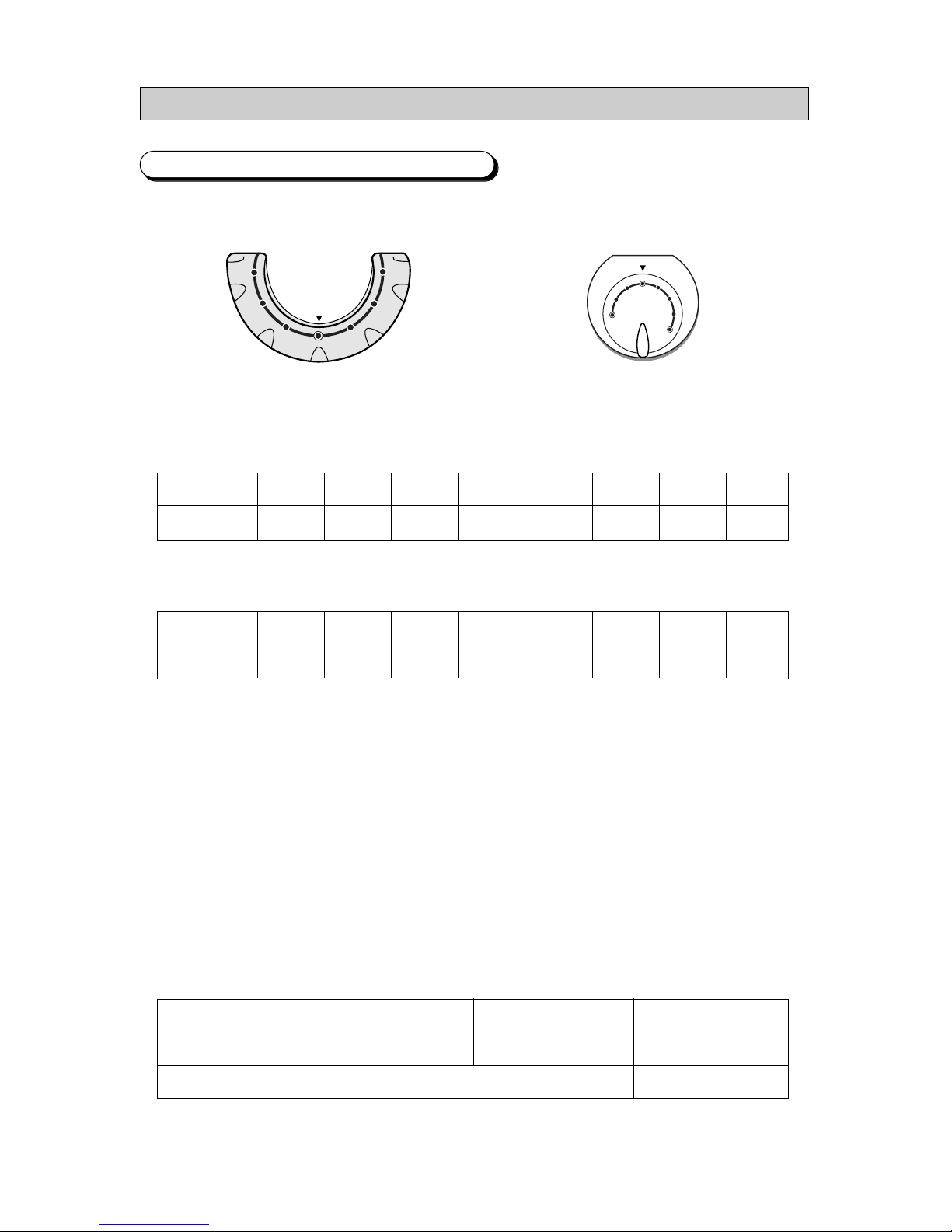
1) Tempera ture choice of freezer
·You can choose to ⑧ From ①
·Follows are control temperature by KNOB position.
Freezer temperature control refrigerator temperature control
KNOB position
control temperature
①
-16.0
②
-17.0
③
-18.0
④
-19.0
⑤
-20.0
⑥
-21.0
⑦
-22.0
⑧
-23.0
2) Temperature choice of refrigerator
·You can choose to ⑧ From ①
·Follows are control temperature by KNOB position.
NOTE) Temperature contol of freezer and refrigerator is position control by ROTRAY S/W, if it get out of
position it control NOTCH
C. Defrost function
1) Defrost set up by time of COMP ON.
2) Defrost tun Heating → Rest time
3) When initial power on, initial defrost run defrost of freezer and refriger ator in 4 hours of COMP
ON. Since initial
(R →R, F →R →R, F ... Cycle operating))
4) ON/OFF of defrost - heater control by EVA-SENSOR If EVA-SENSOR is problem (short 10 pen),
it run just rest time and then finishes defrost function without heating.
5) During defrosting it maintain COMP and FAN state and after finish defrost-heating rest time
is 10 minutes.
6) Follows are defrost heating ON point and OFF point that operate by EVA-SENSOR.
KNOB position
control temperature
①
5.0
②
4.0
③
3.0
④
2.0
⑤
1.0
⑥
0
⑦
-1.0
⑧
-1.0
HEATER ON dot
HEATER OFF dot
REFRIGERATOR
BEIOW+10℃
FREEZER
BEIOW -5℃
REMARK
17℃
TEMP, FRE
TEMP, REF

-20-
D. TEST FUNCTION
▶ TEST function is function for test,SVC and fair test of PCB and product.
▶ TEST S/W choose and confirm function of product and then POWER ON to run self diagnosis.
1) FORCED OPERATING FUNCTION
● Pressed once TEST S/W on MAIN PCB. If so COMP and F-FAN run at once. Thus be careful because
occur COMP over load.
(Refrigerator FAN control ON/OFF by temperature)
● Since it set up forced operating function, it always run COMP and F-FAN and display lamp on MAIN
PCB with ON/OFF 0.1 second periodically.
(Refrigerator FAN control ON/OFF by temperature)
● In 24 hours forced operating function of freezer and refrigerator operate and finish then run normal mode
by KNOB position of temperature setting up.
● During forced operating function if you want to stop it first power OFF and then power on or choose
TEST cancellation mode.
2) Forced defrost function
● For forced operating pressed once TEST S/W button, it cancel forced operating at once and refrigerator
forced defrst function with display forced defrost position ON/OFF lamp on MAIN PCB 0.5 secoonds
periodically. If press one more TEST S/W bueeon display refrigerator and freezer defrosting.
● If forced defrost choose, COMP and FAN power OFF and defrost heater on at once, At this time,
if sensing temperature of EVA-SENSOR over 12℃ defost heater power off and operate rest time normal mode.
● After heating finish it need 10 minal mode
3) TEST FUNCTION CANNCELLATION MODE
● Duting refrigerator and freezer run forced defrost function press one more TEST S/W button if so forced
defrost cancel and rest in 10 minutes and then turn normal mode.
OPERA TING
OPERA TING BEFORE OPEN STEP
“HIGH”
OPERA TING BEFORE SETTING UP STEP
-21-
E. self diagnosis function
1) Power on refrigerator and it run seif diagnosis function about 2 seconds at the inner part.
2) If no preblem it turns normal mode.
3) If find prebiem display lamp of PCB show errw position like lower list and everything don’t operate until repair
error position.
4) After refrigerator power off and then power on for confirming conditiom.
5) Thus if you want to know OPEN/SHORT of temperature sensor on SVC, power off and on if it run self
diagnosis function.
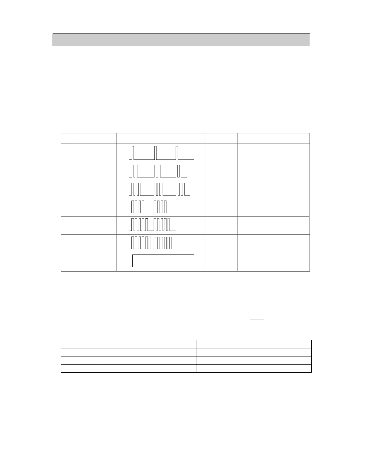
6) When error occur LAMP display method.(Lamp on time : 0.3 seconds ( ON/OFF) Lamp off time : 2 seconds)
● In case of many problems find it display error position in order.
<Example of error display>
① When problem R-ROOM SENSOR display lamp operating.
(0.3 seconds ; ON/OFF) Four times →2 seconds OFF - REPEAT -
② When problem R-ROOM SENSOR and F-ROOM sensor at the same time display method.
(0.3 seconds ; ON/OFF) Three times →2 seconds OFF - REPEAT -
※ Tem perature contre control operating by ROTRAY SWITCH
F. Quick heating operating
1) If freezer heating sensor OPEN/SHORT error at freezer heating it runs just rest time without heating..
2) If refrigerator heating sensor OPEN/SHORT error at refrigerator heating it runs jest time without heating.
1
2
3
4
5
6
7
F DEFROST
SENSOR
R DEFROST
SENSOR
F SENSOR
R SENSOR
F Rotary S/W
R Rotary S/W
NORMAL MODE
-.OPEN ERROR
-.SHORT ERROR
-.OPEN ERROR
-.SHORT ERROR
-.OPEN ERROR
-.SHORT ERROR
-.OPEN ERROR
-.SHORT ERROR
-.OPEN ERROR
-.OPEN ERROR
-. SENSOR IS BELOW -50℃
-. SENSOR IS BELOW +50℃
-. SENSOR IS BELOW - 50℃
-. SENSOR IS BELOW +50℃
-. SENSOR IS BELOW - 50℃
-. SENSOR IS BELOW +50℃
-. SENSOR IS BELOW - 50℃
-. SENSOR IS BELOW +50℃
Vntil operating initial 5minutes
On
Off
On
Off
On
Off
On
Off
On
Off
On
Off
On
Off
No.
ITEM
Led Display
Remark Problem
OPEN ERROR
SHORT ERROR
SECTION
INITIAL SEIF DIAGNOSIS(OFF/ON)
STOP ERROR DISPLA Y OPERA TING
“HIGH”
“MID”
-21-
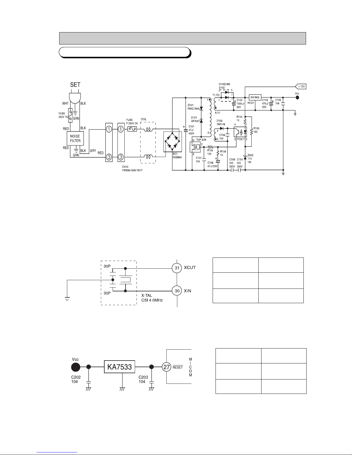
8. CIRCUIT OPERATING THEORY
1) Power is on and makes about DC 300V through BD1.
2) TOP S/W is switching the best condition automatically.
Electric current run between D and S of TOP S/W and occur electric current in TRANS and when power of D-s is
off storing electric current of TRANS pass to secondary voltage.
3) Voltage main 12V. This is applied to display, relay and 5V power of sourcr and Main PCB
1) Tish needs function for CLOCK occurrence and time calculation.
In case of SPEC of RESONATOR change abnormal mode run because of changing Timming system of MICOM.
1. Power suooly part
2. OSCILLATOR
3. RESET PART
TERMINAL
Xin(#30)
Xout(#31)
FREQUENCY
4MHz
4MHz
TERMINAL
Vcc
RESET
VOL TAGE
DC 5V
DC 5V
8-1. ELECTRONIC MODE
-22-
1) RESET part is intialize RAM of MICOM and others when power is on or power is inferruoted for some time It will make
whole program runs from the first status. When power is supplied, reset voltage is “LOW”status for a few seconds and
turn into “HIGH”(Vcc Voltage) status in the normal opweating.
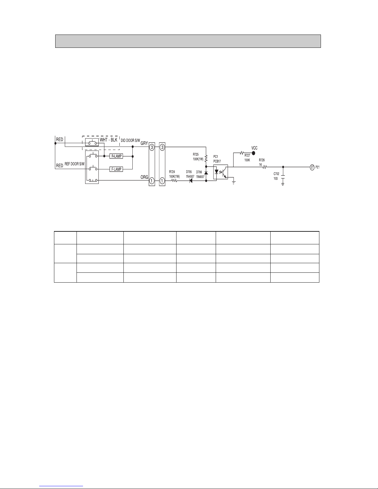
1) DOOR S/W sensing part doesn,t sense Door of Fand R room on each micom.
2) Lamp control door is opened, door S/W pin NO 3 opened and voltage no touching No1 of CN 27 and MICOM input Then the
door-open is sensed.
3) When the door is opened, Door S/W pin No 3 opened and voltage no touching No 1 of CN No 27 and MICOM input.
Then the door-open is sensed.
→ It makes door alarm after 2 minutes
This time F,R DOOR must close at the same time for stopping Door alarm.
4) DID DOOR S/Whave no each sensing parts and control lamp ON/OFF by contact dot of DOOR.
4. DOOR S/W SENSING PART
ITEM
F
R
DOOR CONDITIONS
CLOSE
OPEN
CLOSE
OPEN
DOOR S/W CONTACT
OPEN
CLOSE
OPEN
CLOSE
LAMP
OFF
ON
OFF
ON
MICOM INPUT VOLTAGE
OUTMODE
5V
OUTMODE
5V
CN72PIN NO1 CONTACT
ON
OFF
ON
OFF
-23-
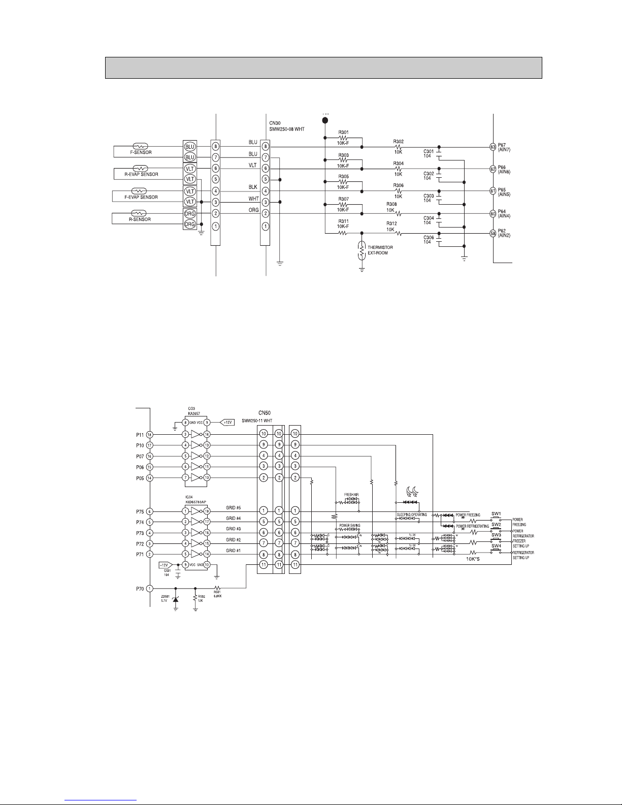
1) Thermistor is used for sensing which has negative resistance coffiecient to the temperature.
R 302, 4, 6, 8, 12, C301~C306 are pares for preventing noise.
2) MICOM input voltage, Vf of sensor is Vf=(R+hx x Vcc)/(R301+Rth) (Rth : sensor resistance)
1) KEY SCAN and display operating
It is used for No 5 of MICoM NO #2, 3, 4, 5, 6,
It operates “high”10 msec periodically for 2 msec cycle : MICOM pin No : #2
→ #3 → #4 → #5 → #6
This signal pass by IC 04 (UDN 2981 or KID 65783AP) from Input dot to Dotput dot.
Voltage of peak to peak is about 11V (DC RMS 1.5V)
5. TEMP·SENSING PART
6. KEY SCAN AND DISPLAY PARTS
 Loading...