

Page 1
Model : SR-42/43
Model : SR-38/39
REFRIGERATOR CONTENTS
1. Safety Precautions and warnings
2. Product specifications
3. Electrical part specifications & standard
4. Product dimension
5. Identifying and disassembling the parts
6. Schematic diagram of coolant gas
7. Circuit diagram
8. Packing dimension
9. Schematic diagram of cold air flow
10. Troubleshooting method
11. Exploded view & part list
12. How to disassemble of freezing
13. How to disassemble of refrigerating
circulation
compartment
SR-42/43
SR-38/39
compartment
Page 2
1. Safety precautions and warnings
Read all instructions before using this appliance in order to avoid risk of accident or possible damage.
Warning/Caution Description of symbols
Indicates prohibition
This symbol is intended to
Warning
Caution
alert the user to the
possible death or injury.
This symbol is intended to
alert the user to the
possible injury or damage.
Do not disassemble
Do not contact
Adhere the instruction strictly
Unplug from the electrical outlet
Earth the appliance to avoid the
risk of an electric shock
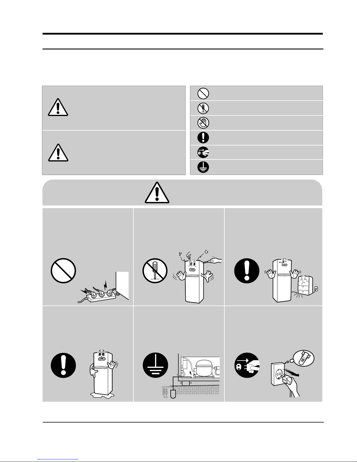
Warning
Do not plug multiple electrical
appliances into the same
outlet.
• This may cause abnormal
heating or a fire hazard.
Prohibition
Check the operating
environment.
• Do not install the refrigerator in a
humid (with condensation)
location or on an unstable
surface.
Do not attempt to make
repairs yourself.
•
Do not disassemble
Do not attempt to make
repairs yourself.
•
This could lead to fire
hazard or abnormal
operation causing severe
personal injury.
This could lead to fire
hazard or abnormal
operation causing severe
personal injury.
Make sure the power cord is
not crushed or damaged.
•
Repair immediately all power
cords or outlets that have
become frayed or otherwise
damaged.
Make sure the power cord is
not crushed or damaged.
•
Repair immediately all power
cords or outlets that have
become frayed or otherwise
damaged.
Samsung Electronics 1
Earth Unplug
Page 3
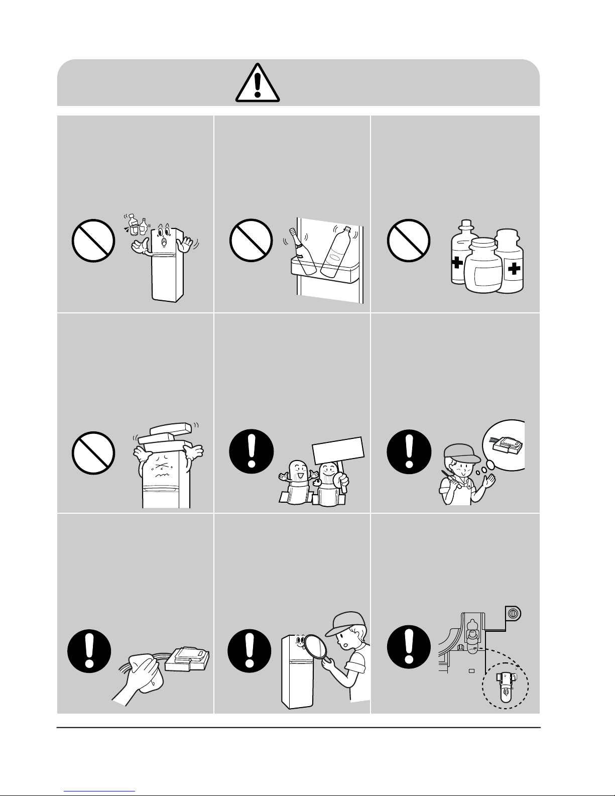
Caution
Do not store bottled food
or drinks in the freezing
compartment.
• Bottles may explode
causing personal injury.
Prohibition
Do not put anything on top
of the refrigerator.
• Opening or closing the door
may trigger loose items to
slip and cause injury.
Do not store food in an
unstable manner.
• Opening the door may
trigger loose items to slip
and cause injury.
Do not store anything other
than food in the refrigerator.
• Medical supplies which need
to be under strict temperature
control should not be stored in
the refrigerator.
Prohibition Prohibition
When replacing electric
components, be sure to
use rated components.
• Check the model, rated
voltage, rated current,
operating temperature etc.
of the component.
When servicing the
refrigerator, completely
remove dust or foreign
substances from the
housing, electric
connections and etc.
•
This can protect against the risk of
firehazard caused by tracking and short
circuit
Rated
components
P r o h i b i t i o
When servicing the refrigerator,
completely remove dust or foreign
substances from the housing,
electric connections and etc.
• This can protect against the risk of
fire hazard caused by tracking and
short circuit.
2 Samsung Electronics
After servicing the refrigerator, be
sure to check the components are
reassembled in a correct manner.
• The serviced unit should be
reassembled and returned to its
original assembly state.
Check the electrical parts for
the trace of moisture
penetration.
• When the trace of moisture
penetration is detected,
replace the part or try
insulation tapping.
Page 4
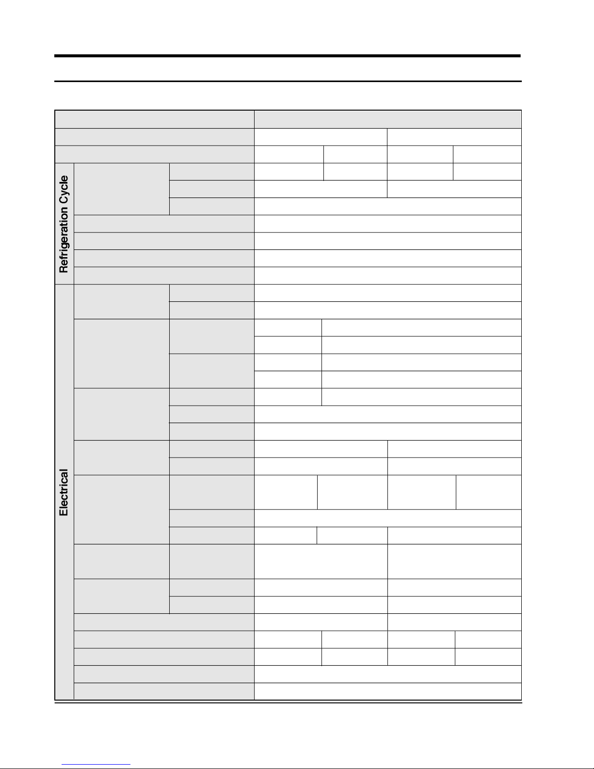
3. Electrical part specifications & standard
[CFC-FREE]
ITEM
Model
Power source
Compressor
Evaporator
Condenser
Capillary tube
Thermostat
Defrost-thermo
Defrost-timer
Dryer
Model
Starting type
Oil charge
Freezer
Refrigerator
Bimetal
(OFF/ON)
Thermal fuse
Type
Cycle
STANDARD
SR-38/39 SR-42/43
110V/60Hz
SD162C-L1W2
127V/60Hz
SD162P-L1W2
220V/50,60Hz
SD162H-L1U2
C.S.R
FREOL ∂ –15c / 200cc
Split fin type
Forced & natural convection
Molecular sieve
I.D 0.75 x L3400 (mm)
PFN – C174S–03C
D–705–E8
Type
Oper. temp.
Regularity
Oper. temp.
TMDE714F1
ON : –5 ±3˚C / OFF : 12±3˚C
AC 250V / 5A
AC 250V / 10A
72±4˚C
TMDE714A1
6hr 35min
230,240V/50Hz
SD162Q-L1U2
R.S.C.R
Time
Model
PTHAS-T100M200B
13min 40s
PTHAS-T330M385D
Starting-relay
Resistance
4TM427
10Ω±20%
4TM317
33Ω±20%
4TM265
4TM222
Model
Overload
protector
Motor-fan
Close temp.
Open temp.
Cooling
Running
PHBYY-53
125±5˚C
AMRHB-010ZQRB
8µF/250VAC
RHBYY-53
69±9˚C
130±5˚C
RHBYY-53
PHBYY-53
125±5˚C
AMRHB-010WTEB
3.5µF/350VAC
Capacitor
Starting
Motor-geared
Heater-defrost
Lamp
Door-Switch
Earth screw
4 Samsung Electronics
100µF/250VAC
M2BC18AR02
130W/93Ω
110V/15w
130W/124Ω
130W/372Ω
127V/15W
250V/0.5A
BSBN(Brass screw)
M2LC18AR02
220V/15W
–
130W/443Ω
240V/15W
Page 5
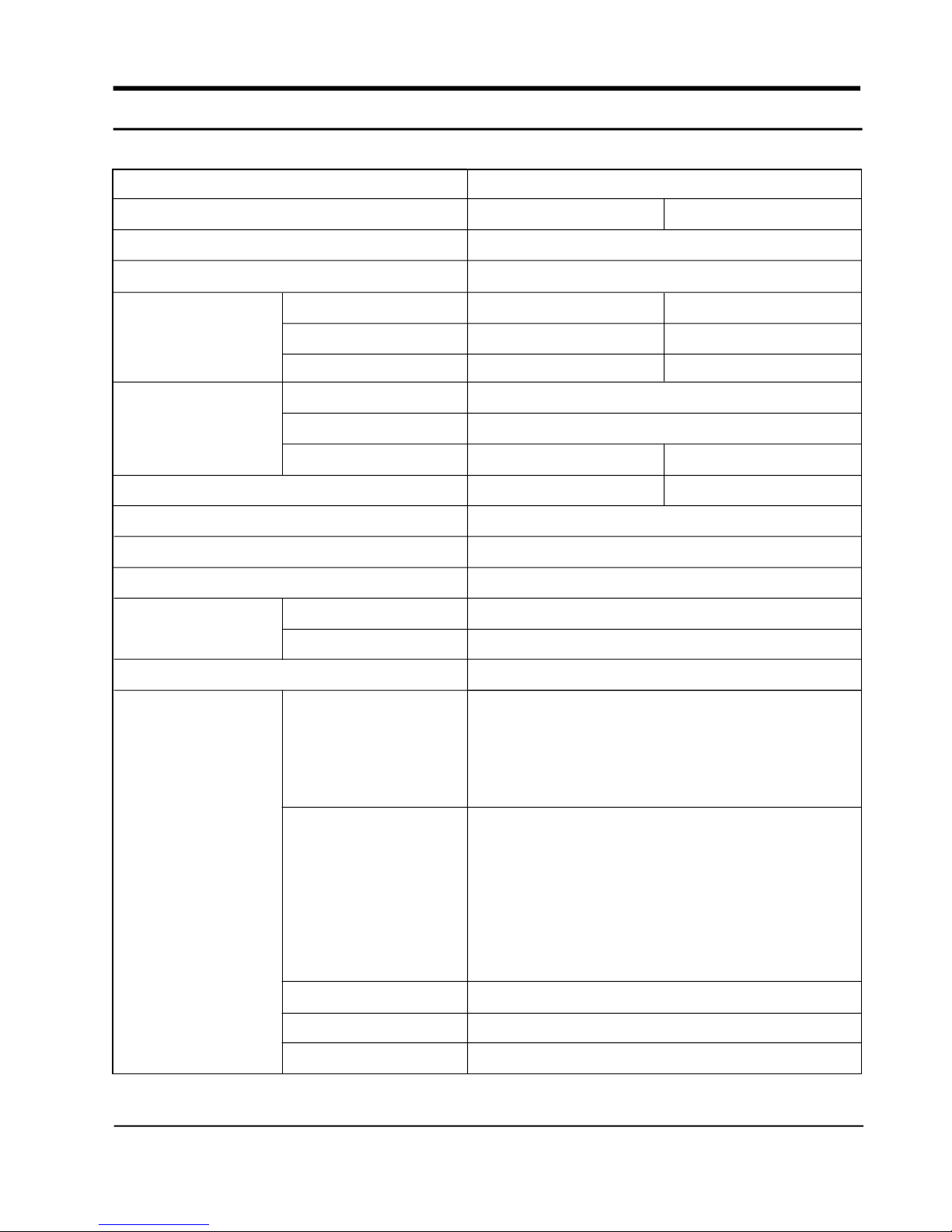
2. Product Specifications
Model name
Power source
Net capacity
(l t / cu.ft)
Net dimension
(mm)
Net weight (kg)
Temperature control
Foam insulation
ITEM
Type
Refrigerant
Defrosting
Freezer
Refrigerator
Total
Width
Depth
Height
Cabinet
Door
STANDARD
SR-38/39
2-Door Freezer/Refrigerator
AC 110V/60Hz, 127V/60Hz,220V/50~60Hz, 240V/50Hz
99(3.5)
225(7.9)
324(11.4)
670
650
1682
67
R-134a(150gr)
Dial(Thermostat)
Automatic(Start-Finish by Timer)
Cyclo-pentane
Cyclo-pentane
SR-42/43
99(3.5)
261(9.2)
360(12.7)
1759
70
Liner / Door panel
Accessory parts
Door
storage
Inside
storage
Interior lamp(H/M)
Movable caster
Angle adjustment
ABS(SD-0150)
3 Guard-freezer
1 Guard-egg
1 Guard-variety
1 Guard-jumbo
1 Base-tray ice 1 Tray-vegetables
1 Case-tray ice, assy 1 Cover-vegetable
1 Tray-ice cube 2 Shelf-refrigerator
1 Shelf-freezer 1 Shelf-chilled (L, )
1 Tray-chilled room(H,M,G) 1 Shelf-chilled ,wire(N)
1 Cover-chilled room(H,M,G) 1 Shelf-ref wire (L,G, N)
2 Shelf-ref wire (G, N)
2 (Refrigerator) / 1 (Refrigerator)
2 (Rear)
2 Legs (Front)
Samsung Electronics 3
Page 6
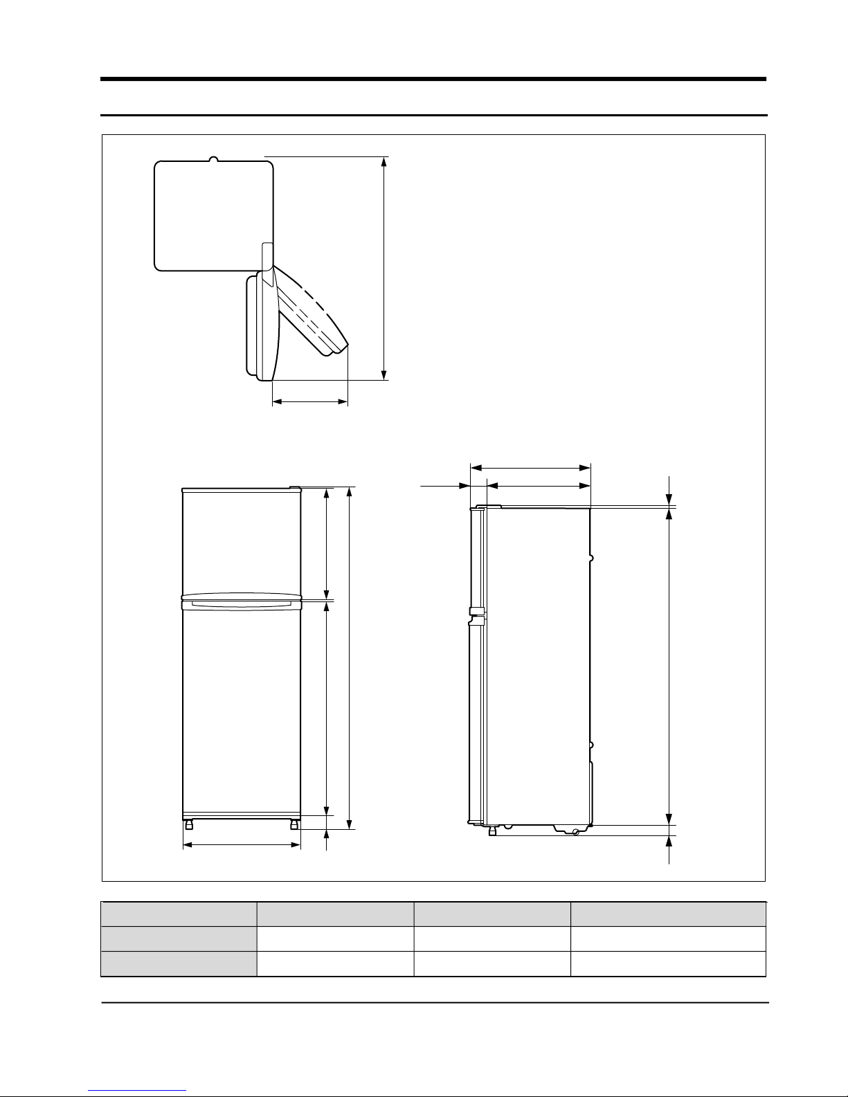
4. Product Dimension
452
1259.5
80.5
650
569.5
670
17
570
9
A
B
50
88
MODEL
SR-42/43
SR-38/39
Samsung Electronics 5
A
1759
1682
B
1078
1001
Remark
Page 7
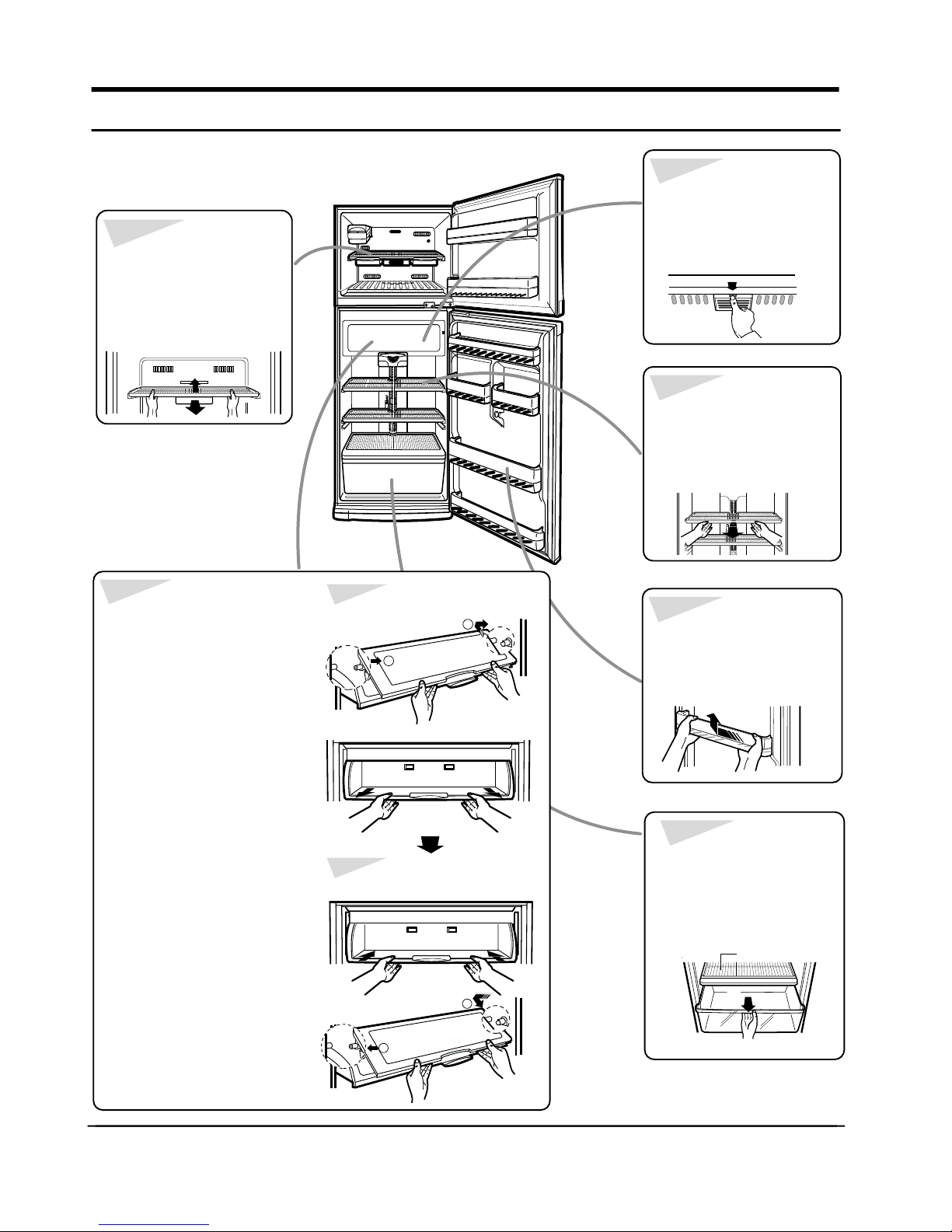
5. Identifying and disassembling the parts
To remove shelves in the
freezing compartment
• Frist remove the icemaking
molds. Tilt the shell up at
front, then lift it up pull it out
of the tracks.
To remove bio
deodorizer
• While pushing the front end
knob of the bio deodorizer,
pull it downward to
disengage.
To remove shelves in the
refrigerating compartment
• Hold the shelf by the
front and pull it forward
of the rack.
To remove shelves in the
chilled compartment
• Lift up the cover, push the
cover to the right (as shown)
until the mounting hook(1)
disengages, then disengage
the other mounting hook (2)
and pull out the cover.
• Pull the shelf forward until it
stops. then lift it up and pull it
out.
• With shelf front raised slightly,
engage, the roller between the
rails and slide it back.
• To repace the cover, first
engage the mounting hook (1)
as shown, then engage the
other hook (2) and push in.
Disassemble
2
Reassemble
1
To remove door bins
• While pushing the bin
to the left, lift it up to
disengage.
To remove storage
drawers and covers
• Lift up to remove the
cover. Pull the drawer helf
way out, then lifting it up,
pull it out completely.
covers
2
6 Samsung Electronics
1
Page 8
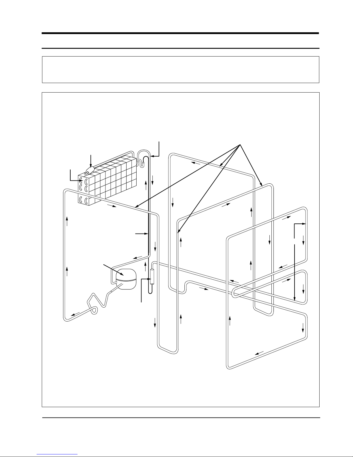
6. Schematic diagram of coolant gas circulation
COMPRESSOR --> CLUSTER PIPE --> HOT PIPE --> DRYER --> CAPILLARY TUBE
--> EVAPORATOR --> ACCUMULATOR --> SUCTION PIPE --> COMPRESSOR
ACCUMULATOR
EVAPORATOR
CAPILLARY TUBE
COMPRESSOR
SUCTION PIPE
CLUSTER PIPE
HOP PIPE
Samsung Electronics 7
DRYER
Page 9

7. Circuit diagram
7-1 [220V/50, 60Hz, 230~240V/50Hz] SR-42/43,SR-38/39
SR-42/43, SR-38/39 (H-OPTION)
YEL
C(3)
M
D(4)
S/BLU
S/BLU
DEFROST
ÐTIMER
A(1)
BRN
B(2)
BIMETAL
FAN-MOTOR
F-THERMO
WHT
BRN RED
F.M
DEFROSTÐHEATER
PNK
THERMAL-FUSE
G.M
GEARED-MOTOR
PNK
N A
GRY
L
LAMP
L
W/BLK
4
3
2
DOOR S/W
"B"
E
RED
1
RED
RED
SR-42/43, SR-38/39 (H-OPTION )
YEL
C(3)
M
D(4)
S/BLU
DEFROST
ÐTIMER
A(1)
BRN
B(2)
BIMETAL
FAN-MOTOR
F-THERMO
WHT
BRN RED
F.M
PNK
THERMAL-FUSE
DEFROSTÐHEATER
PNK
GRY
LAMP
L
4
3
2
DOOR S/W
"B"
1
N A
E
RED
RED
GRY – GRAY
PNK – PINK
BRN – BROWN
WHT – WHITE
YEL – YELLOW
RED – RED
S/BLU – SKY BLUE
BLU – BLUE
BLK – BLACK
W/BLK –
WHITE/BLACK
ORG – ORANGE
PRP – PURPLE
2
3
RED
1
OVERLOAD
PROTECTOR
S/BLU
S/BLU BLU
CONDENSER RUNNING
2
3
P.T.C RELAY
RED
S/BLU
S/BLU BLU
CONDENSER RUNNING
2
5
M
6
S
ÒBÓ
E
C
COMPRESSOR
3
1
OVERLOAD
PROTECTOR
2
3
P.T.C RELAY
5
M
6
S
E
C
COMPRESSOR
7-2 [110V/ 60Hz, 115V/60Hz, 127V/60Hz] SR-42/43,SR-38/39
SR-42/43, SR-38/39 (H-OPTION)
YEL
C(3)
D(4)
S/BLU
S/BLU
M
DEFROST
ÐTIMER
A(1)
BRN
B(2)
BIMETAL
FAN-MOTOR
F-THERMO
WHT
BRN RED
F.M
PNK
THERMAL-FUSE
G.M
GEARED-MOTOR
DEFROSTÐHEATER
PNK
GRY
LAMP
L
W/BLK
4
3
2
DOOR S/W
"B"
1
N A
E
RED
RED
RED
SR-42/43, SR-38/39 (H-OPTION)
YEL
C(3)
D(4)
S/BLU
M
DEFROST
ÐTIMER
A(1)
BRN
B(2)
BIMETAL
F.M
FAN-MOTOR
F-THERMO
WHT
BRN RED
THERMAL-FUSE
PNK
DEFROSTÐHEATER
PNK
N A
GRY
LAMP
L
L
W/BLK
4
3
2
DOOR S/W
GRY – GRAY
"B"
E
PNK – PINK
BRN – BROWN
WHT – WHITE
RED
YEL – YELLOW
RED – RED
S/BLU – SKY BLUE
1
RED
BLU – BLUE
BLK – BLACK
W/BLK –
ORG – ORANGE
PRP – PURPLE
WHITE/BLACK
S/BLU
CONDENSER STARTING
S/BLU
S/BLU
CONDENSER RUNNING
BLU
BLK
2
1
3
5
6
M
S
E
C
COMPRESSOR
8 Samsung Electronics
2
3
RED
1
OVERLOAD
PROTECTOR
S/BLU
CONDENSER STARTING
S/BLU
S/BLU
CONDENSER RUNNING
BLU
BLK
2
1
3
5
6
M
S
ÒBÓ
E
C
COMPRESSOR
2
3
RED
1
OVERLOAD
PROTECTOR
Page 10

10. Troubleshooting method
10-1 The refrigerator does not operate
Is the interior
light on when the door switch
is pushed?
Yes
Does the compressor operate?
Yes
The compressor is operated for more
than 30 minutes and the refrigerator.
Make sure the refrigerator is plugged in
No
at the wall outled.
Yes
No
thermometer in the freezer compartment
Make sure that the
is electrically connected.
Yes
Check the defrost timer
Yes
Check the P.T.C. relay
Yes
Check the overload relay
No
Replace the defective part
If the fan operates when you
No
push the door switch, it is normal
(Replace if it is defective)
No
Replace the defective part
No
Check the electrical connection
Yes
The compressor is defective
The freezing cycle has a problem
Samsung Electronics 11
Yes
Check the condenser
Yes
The compressor is defective
No
Check for the abnormalities
Page 11

10-2 Defrosting mechanism does not work
Check that the defrost timer
No
operates properly
Yes
Check the temperature fuse
Yes
Check the bimetal thermometer
Yes
Check the defrost heater
No
No
No
10-3 Defrosting mechanism does not work
Replace the defrost timer
Replace the temperature fuse
Replace the bimetal thermometer
Replace the defrost heater
Does the cooling fan operate?
Yes
Is the freezer defrosted normally?
Yes
Is the door closed properly?
Yes
Is the door stopper hinge normal?
Yes
Is too much food stored in the
freezer compartment?
No
• Check the cooling fan motor
• Check the door switch
No
• Defrost timer
• Temperature fuse/Bimetal thermometer
• Defrost heater
No
• Check that the door gasket is properly
seled, check for the damaged gasket.
No
• Correct or readjust the door stopper
hinge
No
• Tightly cover stored ice cubes.
• Tightly cover stored frozen food.
• Destribute food evenly in the comparment.
12 Samsung Electronics
Page 12

10-4 Trouble check for the cooling cycle
Symptom
• The EVAP cools down and warms
again.
• The condenser warms in proportion
as the EVAP cools.
• The process continues to repeat.
• The condenser is cold.
• The EVAP is not cold.
• The temperature of the compressor
is high.
• No difference in temperatures
between suction pipe and discharge
pipe.
• The temperature of the compressor
is maintained at room temperature.
• The EVAP does not cool down.
Cause Suggestions
Moisture in the refrigerant
causes the malfunction.
Foreign substances hamper
the cooling cycle.
The compressor is defective
Replace the refrigerant
Locate the disturbed section
and make repairs
Replace the compressor
• Frost on the suction pipe.
• The condenser is overheated.
• The refrigeration in the EVAP is
not effecient.
• The condenser is cold.
• The compressor surface
temperature is high.
• The refrigerator is not easily get
cooled.
Too much refrigerant Replace the refrigerant
Refrigerant leaks.
(Slight refrigerant leakage
causes partial cooling with
frost on the EVAP)
After welding the leaked spot,
replace the refrigerant
Samsung Electronics 13
Page 13

10-5 Diagnosing the main components
Components
Compressor
P.T.C Relay
Condenser
Overload relay
Circuit-motor
&
Fan-motor
Diagnosing methods and criteria Location
• Use the tester to measure
the resistance.
– Bring the component to cool down
completely before measuring.
• Use the tester to measure
the resistance.
– Bring the component to cool down
completely before measuring.
• Use the tester to measure
the resistance.
– Bring the component to cool down
completely before measuring.
• Use the tester to measure
the resistance.
• Use the tester to measure
the resistance.
– Bring the component to cool down
completely before measuring.
Measuring point
Primary iwre
Secondary wire
Normal
Approx ∞Ω ~ kΩ
Normal
Approx 10Ω ~ 80kΩ
Normal
Approx 200kΩ
Normal
Approx 100Ω ~ 20kΩ
Approx 10 ~ 500kΩ
Normal
3 ~ 20Ω
Abnormal
0Ω and
Abnormal
0Ω and ∞Ω
Abnormal
0Ω and ∞Ω
Abnormal
0Ω and ∞Ω
Abnormal
0Ω and ∞Ω
∞Ω
Mechanical
compartment
Mechanical
compartment
Electrical
equipment box
Mechanical
compartment
Mechanical
compartment
Freezing
compartment
Rotating blade
geared-motor
Door switch
Defrost timer
Defrost heater
Bimetal
Temperature
fuse
• Use the tester to measure
the resistance.
– Bring the component to cool down
completely before measuring.
• Use the tester to measure
the resistance.
• Use the tester to measure
the resistance.
• Use the tester to measure
the resistance.
– Bring the component to cool down
completely before measuring.
• Use the tester to measure
the resistance.
Normal
Approx 10Ω ~ 20kΩ
Measuring point
A B contact point
When the switch is
on by the contact
Measuring point
Between terminals
Temperature fuse terminal
Normal
Approx 3KΩ ~ 6KΩ
Measuring point
Bimetal terminal
Temperature fuse
terminal
Normal
Approx 200MΩ
Normal
Approx 200KΩ
Approx 10Ω~300KΩ
Normal
Approx 200MΩ
Abnormal
0Ω and ∞Ω
Abnormal
∞MΩ and
Abnormal
0Ω and
Abnormal
∞ MΩ ~ ∞Ω
Abnormal
∞Ω ~ ∞Ω
∞Ω
∞Ω
Refrigerating
compartment
Between the
upper and the
lower doors
Electrical
equipment box
Lower EVAP
EVAP
14 Samsung Electronics
Page 14

11. Exploded View & Parts List
11-1 Freezing compartment
31
30
7
29
26
1
8
2
24
5
3
4
17
16
15
14
13
18
6
19
23
22
20
27
28
21
10
9
25
Samsung Electronics 15
10
11
12
Page 15

NO
DA61-70002A
1
DA67-40180A
2
DA67-10126A
3
DA67-10210C
4
DA61-20119A
5
DA67-20137A
6
DA71-20252A
7
3523-202-340
8
DA67-30266D
9
6002-000454
10
DA47-10107H
11
DA39-20124B
12
DA63-10253L
13
DA63-10254A
14
DA61-20128B
15
DA31-20002A
16
DA63-40119A
17
DA31-10109S
18
DA31-10109V
CODE-NO
DESCRIPTION
BASE-TRAY, ICE
TRAY-ICE(A)
CASE-TRAY, ICE
TRAY-ICE, CUBE(A)
SPRING-ICE
SHELF-FRE
FIXER-GROMMET D/FRE
SWITCH-DOOR
CAP-SCREW
SCREW-TAP, TH
THERMOSTAT
WIRE-LEAD, THERMO
COVER-EVAP, FR
COVER-EVAP, RE
SPRING-FAN
FAN
GROMMET-FAN, MOTOR
MOTOR (220~240V)
“ (110V~127V)
SPECIFICATION
HIPS
P.P
HIPS
GPPS
PI1.0 L162.6
GPPS
ABS
NY 694 VO
P,P
2-4 x 12 STS304
PCC PFN174S
P.P
ABS SCRAP
STS 27
ABS
SILICON
AMRHB-010WTEB
AMRHB-010ZQRB
SR-42/43 SR-38/39
H
1
2
1
1
2
1
3
1
1
2
1
1
1
1
1
1
2
1
1
L N G H M L N
M
1
2
1
1
2
1
3
1
1
2
1
1
1
1
1
1
2
1
1
1
1
1
2
2
1
1
1
1
2
2
0
1
3
3
1
1
1
1
2
2
1
1
1
1
1
1
1
1
1
1
1
1
2
2
1
1
1
1
1
2
2
1
1
1
1
2
2
0
1
3
3
1
1
1
1
2
2
1
1
1
1
1
1
1
1
1
1
1
1
2
2
1
1
1
1
G
1
1
2
1
1
2
1
3
1
1
2
1
1
1
1
1
1
2
1
1
1
1
2
2
2
1
1
1
1
1
1
2
2
2
0
0
0
3
3
3
1
1
1
1
1
1
2
2
2
1
1
1
1
1
1
1
1
1
1
1
1
1
1
1
1
1
1
2
2
2
1
1
1
1
1
1
DA63-10459A
19
6002-000454
20
DA63-10998R
21
DA63-10998Q
22
6002-000213
23
DA59-40129A
24
DA47-10103J
25
DA64-40126C
26
DA63-10886A
27
DA63-10488B
28
DA47-20195F
DA47-20195H
DA47-20195G
DA47-20195J
29
6002-000454
30
DA64-20150M
31
DA67-20168B
COVER-FAN, MOTOR
SCREW-TAP, TH
COVER-EVAP,ASSY(110V~127V)
COVER-EVAP,ASSY(220V~240V)
SCREW-TAP,TH
EVAPORATOR
BIMETAL-THERMO
KNOB-F, THERMO
COVER-AIR
COVER-HEATER
HEATER-DEFROST
“
“
“
SCREW-TAP,TH
TRIM-SHELF
SHELF-FRE(WIRE)
P.P
1-4 x 12 FE, FZY
2-4 x 12 STS304
125, 250/50, 60-5/12
ABS
P.P
A1050
220V/130W
240V/130W
110V/130W
127V/130W
2-4 x 12 STS304
RD-PVC
MSWR10
Indicated part is for electrical safety components
1
1
1
1
1
1
1
1
1
1
2
2
2
1
1
1
1
1
1
1
1
1
1
3
0
0
1
1
1
1
1
1
1
1
1
1
1
1
1
1
1
1
1
3
3
0
0
0
0
1
1
1
1
1
1
1
2
2
1
1
1
1
1
1
1
1
1
1
1
1
1
1
1
1
1
1
3
3
1
1
1
1
1
1
1
1
1
2
2
1
1
1
1
1
1
1
1
1
1
1
1
1
1
1
1
1
1
3
3
0
0
0
0
1
1
1
1
1
1
1
1
2
2
2
1
1
1
1
1
1
1
1
1
1
1
1
1
1
1
1
1
1
1
1
1
1
1
1
1
1
1
3
3
3
1
1
1
1
1
1
16 Samsung Electronics
Page 16

11-2 Refrigerating compartment
14
15
16
17
13
26
24
23
25
24
21
8
1
9
3
19
6
20
4
2
19
9
11
5
7
29
12
18
5-1
22
28
10
6
1
2
3-1
10
11
27
Samsung Electronics 17
Page 17

NO
DA72-40193B
1
DA67-10246B
2
DA72-40235A
3
DA72-40194B
3-1
DA63-30142A
4
DA47-40112L
5
DA47-40114D
5-1
DA64-10147
6
DA63-10395B
7
DA74-30135A
8
DA47-30153B
9
DA47-30153C
DA4730153D
DA47-30153E
DA02-90108A
10
DA63-10487A
11
4713-001035
12
4713-000213
DA64-40140A
13
DA63-10982C
14
DA67-20138A
15
DA63-10255A
16
DA67-10197A
17
6002-000471
18
DA63-40134A
19
DA31-10107D
20
DA31-10107E
DA63-40131A
21
DA31-20108A
22
DA67-20139A
23
DA64-20150P
24
DA67-20022A
25
DA67-20024B
26
DA47-30152D
27
DA47-30152E
28
DA47-30102
29
DA63-10388A
CODE-NO
DESCRIPTION
SPACER-DAMPER, B
ASSY-THERMO, DAMPER
SPACER-DAMPER, A
SPACER-DAPMER, A
COVER-MULTI, REF(X)
SOCKET-LAMP
SOCKET-LAMP(B)
KNOB-DAMPER, THERMO.
COVER-LAMP, REF
HOSE-DRAIN, CONNECT
ASSY-DAMPER
ASSY-DAMPER
ASSY-DAMPER
ASSY-DAMPER
CATALYST-LTC
CAP-PURIFIER
LAMP
“
TRAY-CHILLED, ROOM
COVER-CHILLED, ROOM
SHELF-REF
COVER-VEGETABLE
TRAY-VEGETABLE
SCREW-TAP, TH
GROMMET-MOTOR
GEARED-MOTOR
“
FIXER-CHILLED, ROOM
BLADE-DAMPER
SHELF-CHILLED
TRIM-SHELF
SHELF-REF(WIRE)
SHELF-CHILLED(WIRE)
ASSY-DAMPER (MULTI)
ASSY-DAMPER (MULTI)
COVER-MULTI, REF(M)
COVER-LAMP, REF
SPECIFICATION
FOAM-PS
705-E9C
FOAM-PS
FOAM-PS
P.P
250V 1A
250V 1A
ABS
MIPS
SILICON
SR-38/39(110~127V)
SR-38/39(220~240V)
SR42/43(110~127V)
SR-42/43(220~240V)
T5 W42 L42
P.P
110V/127W
220V~240V
GPPS
“
“
“
“
1-4 x 12 STS304
NBR
M2LC18AR01(220~240V)
M2BC18AR01(110~127V)
ABS
ABS
GPPS
RD-PVC
MSWR10
“
SR-38/39,DEODO.(C)
SR-42/43,DEODO.
S R - 3 8 / 3 9 , NO. DEODO.
SR-42/43, NO.DEODO.
P.P
MIPS
H
1
1
1
0
1
1
0
1
1
1
1
1
0
0
1
1
2
2
1
1
2
1
1
2
1
1
1
2
1
0
0
0
0
0
0
0
0
0
0
SR-42/43
M
L N G H M
1
1
1
1
1
1
0
0
0
1
1
1
0
0
0
0
0
0
1
1
1
1
1
1
0
0
0
1
1
1
0
0
0
0
0
0
0
1
1
1
1
1
1
2
1
1
2
0
0
0
2
0
0
0
0
0
1
0
0
0
1
1
0
0
0
0
0
0
0
0
0
1
1
1
1
0
0
0
0
2
0
1
1
1
1
2
2
0
0
0
0
0
0
0
0
0
0
1
0
0
3
0
2
0
1
1
0
0
1
0
0
0
0
1
1
1
1
SR-38/39
L
1
1
1
1
1
1
1
1
0
1
0
0
1
0
1
1
0
1
0
0
0
1
0
0
1
0
1
1
1
1
1
1
0
1
0
0
1
1
1
1
0
0
0
0
0
0
0
0
1
0
1
0
0
0
0
1
2
1
2
1
1
1
1
0
2
1
1
1
1
2
2
0
1
0
1
0
1
2
2
0
1
0
0
2
0
2
0
0
0
0
0
1
0
0
0
0
0
1
0
1
0
0
0
0
0
0
0
0
0
0
1
1
1
1
1
0
1
0
2
2
1
1
1
1
2
2
0
0
0
0
0
0
2
0
0
0
0
1
0
0
0
0
0
0
0
0
0
0
1
1
0
0
1
1
1
1
G
N
1
1
1
1
0
0
1
1
0
0
0
0
1
1
1
1
0
0
1
1
0
0
0
0
0
0
0
0
0
0
0
0
1
1
1
1
0
1
0
1
0
0
1
1
1
1
2
2
0
0
0
0
0
0
0
2
0
0
0
0
3
2
2
2
1
0
0
0
0
0
0
0
1
1
1
1
1
1
Indicated part is for electrical safety components
18 Samsung Electronics
Page 18

11-3 Door parts
1
3
1-1
2
2-1
12
11
3
10
9
5
4
6
Samsung Electronics 19
8
7
3
13
11
Page 19

NO
CODE-NO
DESCRIPTION
SPECIFICATION
SR-42/43 SR-38/39
H
M L N
G
H M L
G
N
1
DA91-40193B
1-1
DA91-10246B
2
DA91-40235A
2-1
DA91-40194B
3
DA63-30142A
4
DA63-40112L
5
DA67-40114D
6
DA63-10147
7
DA63-10395B
8
DA71-30135A
9
DA71-30142
10
DA71-90108A
11
6001-10487A
12
13
DA71-000213
ASSY-FOAM DOOR, FRE
”
ASSY-FOAM DOOR, REF
”
GUARD-FRE(REF)
GUARD-EGG
TRAY-EGG
GUARD-VARIETY
GUARD-JUMBO
GUIDE-BOTTLE, JUMBO
STOPPER-DOOR(C)
STOPPER-DOOR(A)
SCREW-MACHINE
INLAY-MASCOT
STOPPER-DOOR(B)
SR-42/43 OPTION
SR-38/39 OPTION
SR-42/43 OPTION
SR-38/39 OPTION
GPPS
”
”
”
”
P.P
SCP1 T2.0 ZPC3
POM
TH M4X12 STS304
PET
SCP1 T2.5 ZPC
1
1
0
1
0
3
1
2
2
1
1
1
1
4
1
1
1
1
1
0
0
0
0
1
1
1
1
0
0
0
0
3
3
3
3
1
1
1
1
2
2
2
2
2
2
2
2
1
1
1
1
1
1
1
1
1
1
1
1
1
1
1
1
4
4
4
4
1
1
1
1
1
1
1
1
0
0
1
0
1
3
1
2
2
1
1
1
1
4
1
1
0
0
0
1
0
1
3
1
2
2
1
1
1
1
4
1
1
1
1
0
1
3
1
2
2
1
1
1
1
4
1
1
1
0
0
1
1
3
3
1
1
2
2
2
2
1
1
1
1
1
1
1
1
4
4
1
1
1
1
Indicated part is for electrical safety components
20 Samsung Electronics
Page 20

11-4 Cabinet Parts & Unit
33
1
4
24
2
3
23
30
32
26
28
8
7
6
5
16
29
31
25
27
37
36
40
11
13
18
17
41
38
39
12
11
10
9
19
14
20
23
34
35
21
22
15
Samsung Electronics 21
Page 21

NO
DA63-10969A
1
DA61-10213A
2
DA63-50145A
3
DA60-10124A
4
DA61-10213C
5
DA61-10214A
6
DA63-50159A
7
DA60-40102A
8
DA61-70256A
9
DA60-10124A
10
DA61-30105A
11
DA61-10150A
12
6001-000034
13
DA60-10124A
14
DA71-60196B
15
DA65-20101A
16
DA63-40004A
17
SD162H-L1U2
18
SD162Q-L1U2
SD162C-L1W2
SD162P-L1W2
DA34-10003R
19
DA34-10003U
DA34-10003A
DA34-10003X
CODE-NO
DESCRIPTION
COVER-HINGE, UP
HINGE, UP
SHIM-HINGE, UP
SCREW-TAP, TITE
SCREW-TAP, TITE
HINGE-MID
SHIM-HINGE, MID
WASHER
SUPT-FOOT
SCREW-TAP, TITE
FOOT-FRONT
HINGE-LOW
SCREW-TH
SCREW-TAP, TITE
BASE-COMP, ASSY
CLAMP-COMP
GROMMET-COMP
COMPRESSOR
COMPRESSOR
COMPRESSOR
COMPRESSOR
O/L-PROTECTOR (115/60)
O/L-PROTECTOR (127/60)
O/L-PROTECTOR (220/50)
O/L-PROTECTOR (240/50)
SPECIFICATION
PP
SCP1 T2.5 ZPC3
RD-PVC
ZPC2-Y M6X16
ZPC2-W M6X24
SCP1 T4 ZPC2
RD-PVC T1.0
ID8.5 0D16 T1 NY-66
SHP1 T4.5 ZPC3
ZPC2-Y M6X16
PP
SHP1 T4.5 ZPC3
STS M4X15
ZPC2-Y M6X16
SBHG1 T1.2
SK5
NBR
220V/50Hz,60Hz
230V~240V/50Hz
100~115V/60Hz
127V/60Hz
4TM427PHBYY-53
4TM317RHYY-53
4TM265RHYY-53
4TM222PHBYY-53
H
1
1
1
4
2
1
1
1
2
3
2
1
4
4
1
4
4
1
1
1
1
1
1
1
1
SR-42/43
M L N
1
1
1
1
1
1
4
4
2
2
1
1
1
1
1
1
2
2
3
3
2
2
1
1
4
4
4
4
1
1
4
4
4
4
1
1
1
1
1
1
1
1
1
1
1
1
1
1
1
1
SR-38/39
G
1
1
1
1
1
1
4
4
2
2
1
1
1
1
1
1
2
2
3
3
2
2
1
1
4
4
4
4
1
1
4
4
4
4
1
1
1
1
1
1
1
1
1
1
1
1
1
1
1
1
M
H
1
1
1
4
2
1
1
1
2
3
2
1
4
4
1
4
4
1
1
1
1
1
1
1
1
1
1
1
4
2
1
1
1
2
3
2
1
4
4
1
4
4
1
1
1
1
1
1
1
1
L N G
1
1
1
1
1
1
4
4
2
2
1
1
1
1
1
1
2
2
3
3
2
2
1
1
4
4
4
4
1
1
4
4
4
4
1
1
1
1
1
1
1
1
1
1
1
1
1
1
1
1
1
1
1
4
2
1
1
1
2
3
2
1
4
4
1
4
4
1
1
1
1
1
1
1
1
DA35-10002C
20
DA35-10002D
DA63-10722A
21
DA65-10002A
22
DA67-40309A
23
6002-000213
24
D A 6 7 - 1 0 4 3 0 C
25
6002-000213
26
DA45-10003F
27
DA45-10003E
PTC-RELAY
PTC-RELAY
COVER-RELAY
CLAMP-RELAY, COVER
TRAY-DRAIN, WATER
SCREW-TAP, TH
CASE-JUNCTION
SCREW-TAP, TH
TIMER-DEFROST
TIMER-DEFROST
912X32E100MQ16APE3
912X35E330MT20APE2
PP
SK-5
PP
1-4X12 FE, FZY
PP
1-4X12 FE, FZY
100V~127V 6H40M
220V~240V 6H40M
1
1
1
1
1
2
1
1
1
1
1
1
1
1
1
1
1
1
1
1
1
1
1
1
1
1
1
1
1
2
2
2
2
1
1
1
1
1
1
1
1
1
1
1
1
1
1
1
1
1
1
1
1
1
1
2
1
1
1
1
1
1
1
1
1
1
1
1
1
1
1
1
1
1
1
1
1
1
1
2
2
2
2
1
1
1
1
1
1
1
1
1
1
1
1
1
1
1
1
1
Indicated part is for electrical safety components
22 Samsung Electronics
Page 22

NO
6002-000213
28
2501-000413
29
2501-000427
2501-000422
DA39-20386C
30
DA39-20386D
31
DA34-10122C
32
DA74-30131A
33
DA63-40237G
34
DA63-40237H
35
DA63-10252A
36
6002-000213
37
DA60-41120B
38
DA63-50196A
39
6002-000453
40
DA64-20189A
41
CODE-NO
DESCRIPTION
SCREW-TAP, TH
C-OIL (RUN)
C-OIL (RUN)
C-OIL (START)
WIRE-HARNESS RELAY
WIRE-HARNESS RELAY
CBF
SWITCH-DOORDRAINHOSE, B
GROMMET-DISCHARGE
GROMMET-DISCHARGE
COVER-TRAY WATER
SCREW-TAP,TH
WASHER
SHIM-HINGE, LOW
SCREW-TAPPING
TRIM-PLATE ABSOBER
SPECIFICATION
1-4X12 FE, FZY
8µF/250VAC
3.5µF/350VAC
100µF/125VAC
220V~240V
100V~127V
BUYER OPTION
GRN 2B
LDPE
NBR P16
NBR P14
PP
1-4X12FE, FZY6
ID8.5 0D16 T0.5
RD-PVC
FH M4X12 STS304
PVC
SR-42/43
H M L N G H M L N G
2
2
1
1
1
1
1
1
1
1
1
1
1
3
1
1
1
1
2
2
2
1
1
1
1
1
1
1
1
1
1
1
1
1
1
1
1
1
1
1
1
1
1
1
1
1
1
1
1
1
1
1
1
1
1
1
1
1
1
1
1
1
1
1
1
3
3
3
3
1
1
1
1
1
1
1
1
1
1
1
1
1
1
1
1
2
1
1
1
1
1
1
1
1
1
1
1
3
1
1
1
1
SR-38/39
2
2
1
1
1
1
1
1
1
1
1
1
1
1
1
1
1
1
1
1
1
1
1
1
3
3
1
1
1
1
1
1
1
1
2
1
1
1
1
1
1
1
1
1
1
1
3
1
1
1
1
2
1
1
1
1
1
1
1
1
1
1
1
3
1
1
1
1
Indicated part is for electrical safety components
Samsung Electronics 23
Page 23

8. Packing dimension
B
A
B
C
A
D
MODEL
SR-42/43
SR-38/39
Samsung Electronics 9
A
695
695
B
717
717
C
1806
1729
D
55
55
Page 24

9. Schematic diagram of cold air flow
• Cold air generated from the
cooling system is distributed to
the freezing compartment and
the refrigerating compartment by
the air circulation fan.
• In the freezing compartment, cold
air is distributed to the
compartment as as well as to the
shelves from the cold air exhaust
port, food is frozen in the freezing
compartment by cold air shower.
• Cold air that comes out of the
freezing compartment is
absorbed back to the lower part
of the cooling system through the
suction port on the median
divider.
• In the refrigerating compartment,
cold air is distributed to the
damper cover through the
median divider. Cold air supplied
to the damper cover passes
through the rotating blade and
evenly cools the refrigerating
compartment.
• After cooling the refrigerating
compartment, cold air is
absorbed to the lower part of the
cooling system through the
suction port on the median
divider.
Freezer
Super fresh
Fresh food
Storage
Bio deodorizer
Cold air suction
compartment
compartment
compartment
drawer
[SR-42/43,SR-38/39]
Cold air
circulation fan
Freezer
Median divider
Damper cover
Rotating blade
Cold air exhaust
10 Samsung Electronics
Page 25
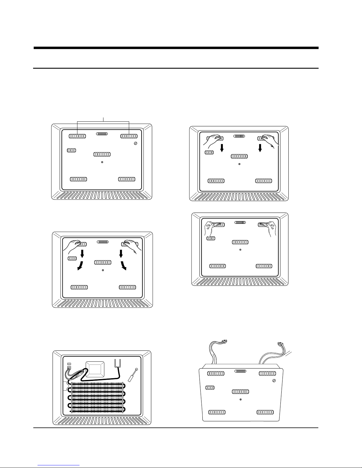
12. How to disassemble of freezing compartment
12-1 COVER-EVAP.ASSY’Y
1) Take out the items in the freezer
2) Dry off the wetness in the handle.
Handle
4) While pressing force downwards, pull the
handle towards the front at the same time.
3) Hold the handle with the hand and press the
elbow towards the COVER-EVAP, ASSY and
press force downwards.
5) When the COVER-EVAP, ASSY is taken apart,
take the necessary corrective measures and this
time put them together.
24 Samsung Electronics
Reference : to improve the friction of
the handle, use rubber
gloves or pick-up tongs.
C O V E R - E V A P ,
ASSY
Page 26

13.
How to disassemble of refrigerating compartment
1. Remove the super fresh compartment cover and its
shelf.
• Lift up the cover, pysh the cover (as shown) until the
mounting hook (1) disengages, then disengage the
other mounting hook (2) and pull out the cover.
• Pull the shelf forward until it stops, then lift it up and
pull it out.
2. Remove the shelves from the fresh food
comparment.
• First remove food from the comparment. With shelf
front raised slightly, pull it forward to disengage.
1
2
3. Disengage the hooks on the lamp cover of the
damper cover.
4. Replace the bulb.
(Before replacing, check the voltage and current of
the bulb. Use rated bulbs only.)
Samsung Electronics 25
 Loading...