

Page 1

CONTENTS
1. Product Specification
2. Operations & Installation
2-1 Checking Parts
2-2 Control Locations
2-3 Connecting Lines
2-4 Installing Handset Batteries
2-5 Charging the Handset
2-6 Using the Handset Carrying Clip
2-7 Turning the Handset On/Off
2-8 LCD Window Icon Descriptions
2-9 Choosing Dial Mode
2-10 Making a Call
2-11 Camp On Busy
2-12 Receiving a Call
2-13 Caller ID Display
2-14 Out of Range Indication
2-15 Battery Level Indicator
2-16 Adjusting Voice Volume
2-17 Choosing Ring Type
2-18 Adjusting Ring Volume
2-19 Key Lock
2-20 Memory Dialing
2-21 Call Log
2-22 Last Number Redial
2-23 Call Time Display On/Off
2-24 Key Beep On/Off
2-25 Base Number Display On/Off
2-26 Tone Dial Switchover
2-27 Setting Ring Delay Time
2-28 Changing Flash Time (Only for German Model)
2-29 Changing PIN (Personal Identification Number)
2-30 Registered Recall
2-31 Barring Calls
2-32 Reset
2-33 Registering New Handset with Base
2-34 Paging
2-35 Intercom Between Handsets
2-36 Call Transfer
2-37 Operating with Additional Base Unit
3. Exploded View & Parts List
3-1 SP-R5200 HANDSET P/L
3-2 SP-R5200 HANDSET Exploded View
3-3 SP-R5200 BASE P/L
3-4 SP-R5200 BASE Exploded View
3-5 SP-R5200 CHARGER P/L
3-6 SP-R5200 CHARGER Exploded View
3-7 SP-R5200 PACKING P/L
3-8 SP-R5200 PACKING Exploded View
4. Electrical Parts List
4-1 SP-R5200 Hand Logic Parts List
4-2 SP-R5200 Hand RF Parts List
4-3 SP-R5200 Base Logic Parts List
4-4 SP-R5200 Base RF Parts List
4-5 SP-R5200 Charger Part List
4-6 Service Subsidiary materials
4-7 PCB Array
5. Block Diagram
5-1 SP-R5200 Base Logic Block Diagram
5-2 SP-R5200 RF Block Diagram
5-3 SP-R5200 Hand Block Diagram
6. PCB Diagrams
7. Schematic Diagrams
7-1 SP-R5200 BASE
7-2 SP-R5200_CLIP CIRCUIT
7-3 SP-R5200 HAND
7-4 SP-R5200 RF
7-5 SP-R5200 CHARGER
8. Trouble Shooting
8-1 Trouble Shooting of Handset Logic
8-2 Trouble Shooting of Handset RF Module
8-3 Trouble Shooting of Baseset
8-4 Trouble Shooting of Baseset RF Part
9. Test Jig Usage
Page 2

Page 3

1. Product Specification
Product Specification 1-1
Item Description
Frequency Range 1881.792MHz~1897.344MHz
Channels 120 Duplex Channels
Channel Separation 1,728MHz
Carrier Power ²250mW (24dBm)
Modulation GFSK
Frequency Stability ² ± 50kHz
Standby Mode : 120hr
Operation Time Talk Mode : 12hr
Charging time : 15hr
Ambient Temperature
Normal : 15ûC~35ûC
Extreme : 0ûC~40ûC
Humidity 0%~90%
Weight
Baseset : 159.1g
Handset : 172.5g
Dimensions
Baseset : 176✕91✕50
Handset : 156✕57✕27mm
Power Supply
Baseset Input : DC 9V 400mA, DC 9V 150mA
Handset Input : 2.4V, 700mA (Ni-CAD)
Compliance
TBR 6
TBR 10
Page 4

2. Operations & Installstion
2-1 Checking Parts
Once you have unpacked your phone, check to make sure that you have all the parts shown below. If any piece
is missing or broken, please call your dealer.
2-1 Operations & Installation
Base
Adapter
Two AA Batteries
(Rechargeable Ni-Cd batteries)
Service Manual
Line Cord
Handset
Page 5

2-2 Control Locations
2-2-1 Handset
Operations & Installation 2-2
1
ABC
2
DEF
3
JKL
5
GHI
4
MNO
6
TUV
8
0
PQRS
7
WXYZ
9
C/R
INT
OK
Antenna
Earpiece
LCD window
Microphone
button
Makes, answers, or ends a call.
INT button
Activates intercom communications.
▲ or ▼ button
Scrolls through menus. Also adjusts volume.
C/R button
Clears characters from the display. Also performs a
switch-hook operation such as call waiting.
button
Confirms the selection. Also powers on/off.
button
Redials the last number you dialed. Also adds
a pause when storing a number in memory.
Rear
Charging
points
Battery cover
Carrying clip
Lamp
OK
Page 6

2-2-2 Base
2-3 Operations & Installation
SP-R5200
Paging button
Allows you to page the handset.
Also used to register a new
handset with the base.
Line lamp
Blinks when a call comes in
and lights steadily when a call
is in progress.
LINE DC 9 V
Base Bottom
DC POWER
socket
Phone Line socket
Page 7

2-3 Connecting Lines
1. Connect one end of the telephone line cord to the phone line socket on the bottom of the base unit, and the
other end to a standard phone wall jack.
2. Connect the modular end of the power adapter to the DC power socket on the bottom of the base unit, and
the other end to a standard AC wall outlet.
Operations & Installation 2-4
3. Route the cords through the recessed channel as shown.
DC 9 V
LINE
DC 9 V
LINE
To AC wall outlet
To phone wall jack
Page 8
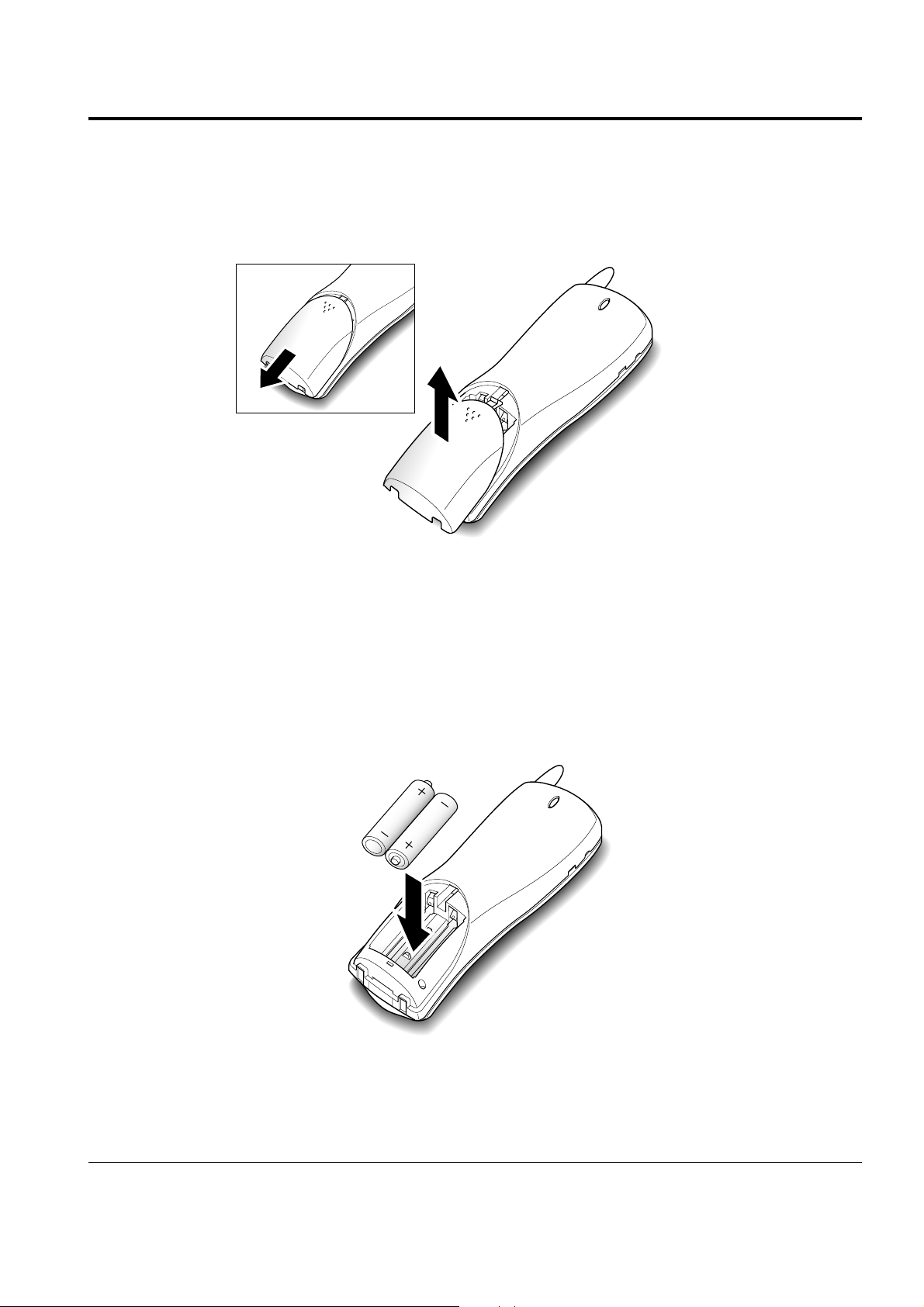
2-4 Installing Handset Batteries
The handset uses the two AA size rechargeable Ni-MH or Ni-Cd batteries supplied.
1. Slide the battery cover in the direction of the arrow, then lift it off.
2-5 Operations & Installation
2. Remove old batteries if any, then insert new batteries observing correct polarity ( + , - ). Reversing the
orientation may damage the handset.
Page 9

Operations & Installation 2-6
3. Replace the battery cover. Make sure that the cover is hooked in place.
4. Slide the cover up until it snaps shut.
Notes:
¥ The batteries need to be replaced if they do not recover their full storage capacity after recharging.
¥ When replacing batteries, always use good quality Ni-MH or Ni-Cd rechargeable AA size batteries.
Never use other batteries or conventional alkaline batteries.
Page 10
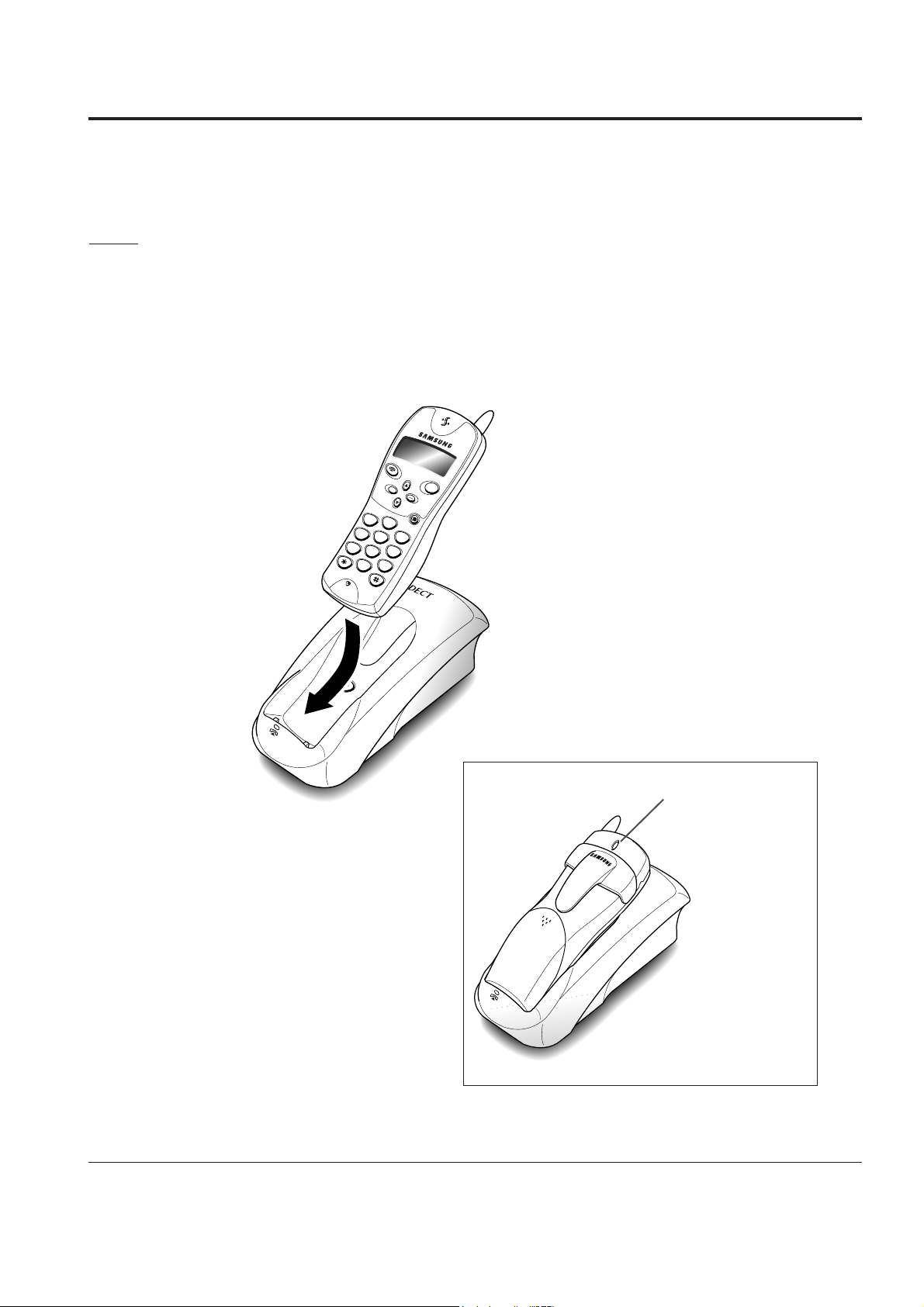
2-5 Charging the Handset
Before initial operation, you should fully charge the handset for more than 15 hours.
To charge the handset, simply place it on the base unit.
The handset can be charged either face up or face down.
Result: When the handset batteries are charging, the handset automatically turns on and the battery icon on
the left corner of the display is scrolling.
2-7 Operations & Installation
SP-R5200
INT
ABC
2
1
DEF
3
JKL
5
GHI
4
MNO
6
TUV
8
0
PQRS
7
WXYZ
9
OK
ON
C
/
R
The lamp comes
on while
charging.
Page 11
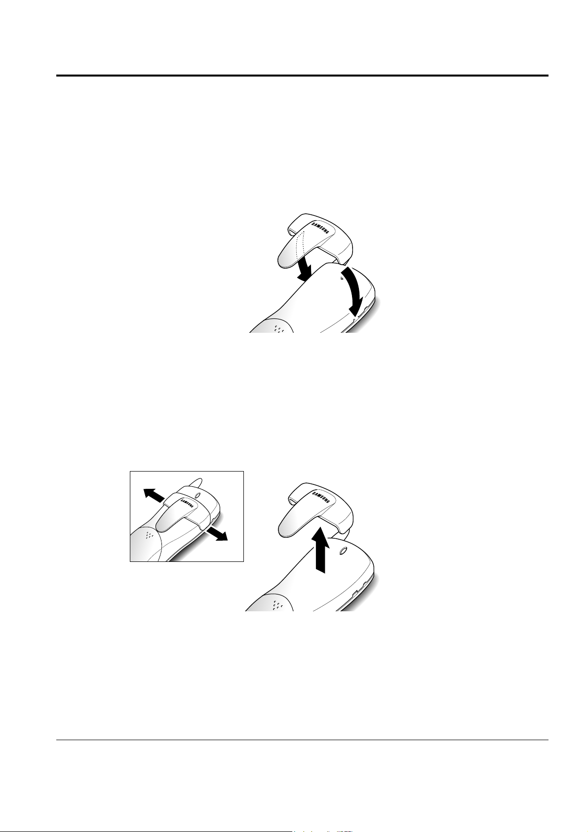
2-6 Using the Handset Carrying Clip
The supplied handset carrying clip allows you to conveniently carry the handset with you. It clips easily to
your belt, waist band, or shirt pocket.
To Attach the Carrying Clip
Attach the carrying clip to the back of the handset. The carrying clip fits into the grooves on the back of the
handset as shown. Make sure that the carrying clip locks into place.
Operations & Installation 2-8
To Remove the Carrying Clip
Insert a coin or screw driver into the slot along the edge of one of its arms, and twist to release. Then lift it off.
Page 12

2-7 Turning the Handset On/Off
When you place the handset in the base unit to charge it, the handset automatically turns on. To turn the
handset on or off in Standby mode, follow these steps:
1. To turn on the handset when the display is off, press button.
Result: All segments in the LCD window turn on briefly, then the phone switches to the Standby mode. The
phone is now ready for use. The display shows the handset number and the base number as shown
below.
2. To turn the handset off, press and hold button for about three seconds until appears in the
display.
Result: appears, then the display turns off.
Notes:
¥ If you purchase an additional handset, you must register the handset to a base. If not, the display
shows when you turn it on and the handset will not work. Refer to ÔRegister New Handset with
BaseÕ on page 2-33.
¥ Nothing will appear in the LCD window when battery power is very low. You should fully charge the
handset before operation.
OK
OK
2-9 Operations & Installation
Base numberHandset number
Page 13
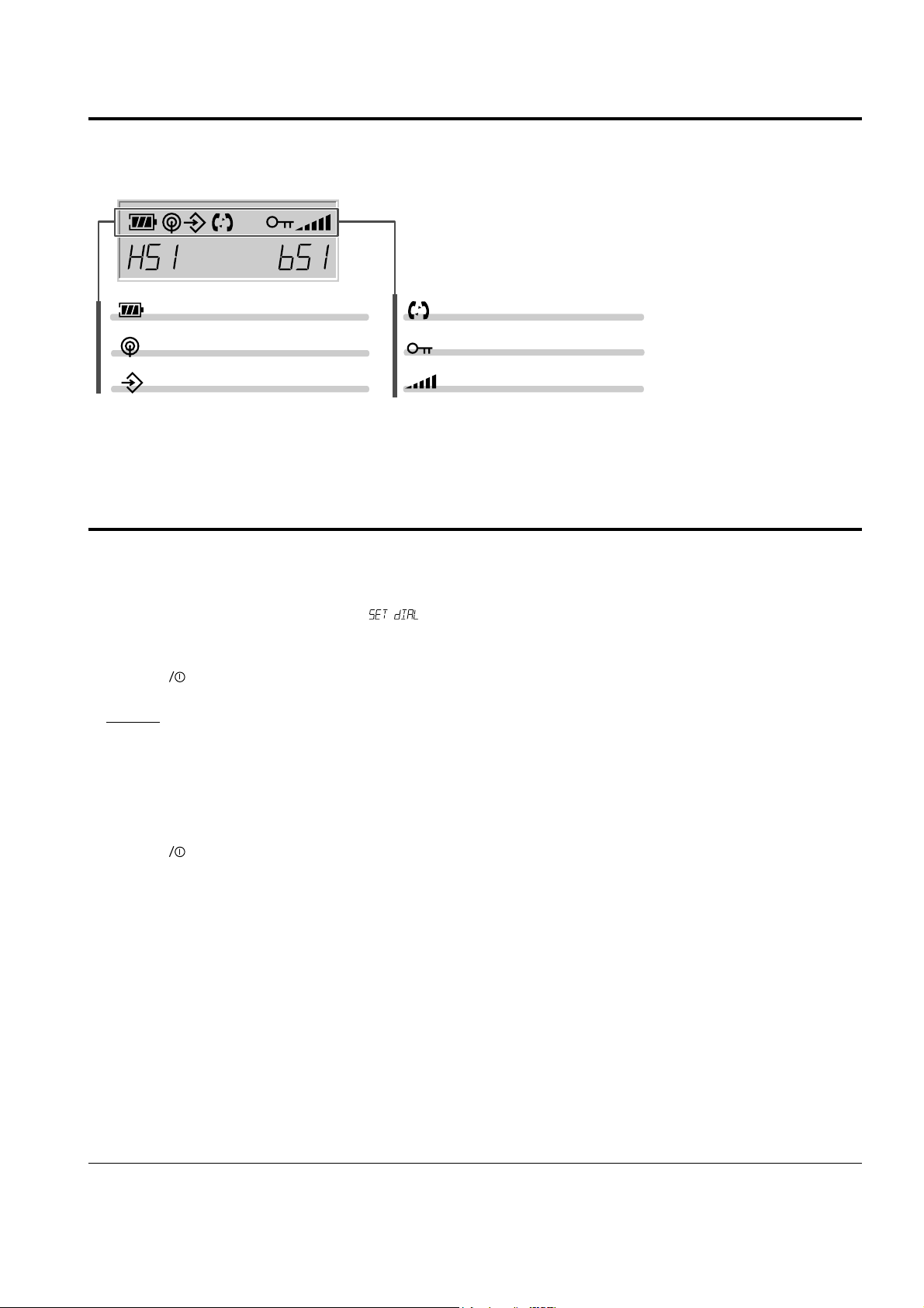
2-8 LCD Window Icon Descriptions
2-9 Choosing Dial Mode
In order to provide compatibility with most telephone systems, your phone can be set to either pulse-dialling
(same as rotary), or tone dialling (DTMF). Your phone is preset to tone mode.
1. Press ▲ or ▼ button repeatedly until appears.
2. Press button to access the menu.
Result: The display shows the current setting;
ÔTONEÕ or ÔPULSEÕ.
3. Press ▲ or ▼ button to choose the desired mode.
4. Press button to confirm.
OK
OK
Operations & Installation 2-10
Battery status icon
In range icon
Memory icon
Handset key lock icon
Volume level icon
Line/Intercom/icon
Page 14

2-10 Making a Call
1. Pick up the handset and press button. You hear a dial tone.
2. Dial the desired number by using the number keypad.
Note:
You can store telephone numbers into one-digit memory cells (0-9) and dial the numbers using the assigned
memory cell number. Refer to ÔMemory DialingÕ on
page 2-20.
3. When the other person answers, speak.
4. To end the call, either press button or replace the handset on the base unit.
Notes:
¥ If you turn the ÔCall Time DisplayÕ feature on, the LCD window displays the call time. For details, see ÔCall
Time DisplayÕ on page 2-23.
¥ To make a call to the last number you dialed, use the ÔRedial Ô feature. For details, refer to ÔLast Number
RedialÕ on page 2-23.
You can enter the desired phone number in Standby mode, and then dial the number. This way of dialing
allows you to make corrections to the number before dialing. Follow these steps:
1. Enter a telephone number. Check the number in the LCD
window.
Notes:
¥ If you make a mistake while entering a number, press C/R button to clear the last digit and correct the
number.
¥ If you press and hold C/R button for more than one second, all digits you have entered are cleared and the
phone returns to the Standby mode.
2. When the number appears correctly, press button.
2-11 Operations & Installation
Page 15

2-11 Camp On Busy
(This feature is available only when you have more than one handset)
This feature allows your handset to wait for connection to the telephone line currently engaged by another
handset. Your handset rings when the telephone line becomes free.
1. You hear a short busy tone if you press button while another handset engages the telephone line.
Result: Your handset is automatically camped on the line.
Note: To cancel this feature, press button any time before the line is free. The handset returns to Standby
mode.
2. Your handset rings and the window displays when the line becomes free.
3. Press button to engage the line while the handset rings. (Press the button within 10 seconds, or the handset returns
to Standby mode.)
Notes:
¥ If an incoming call arrives while your handset rings to tell you the line is free, the ÔCamp On BusyÕ feature is
automatically cancelled and an incoming ring sounds.
¥ Several handsets can be camped on the busy line in chronological order. When the line becomes available to
you, the LCD window displays , and other handsets will display your handset number following the
word .
Operations & Installation 2-12
Page 16

2-12 Receiving a Call
1. When an external call comes in, the phone rings.
Result: The icon on the display blinks, and the green lamp on the back of the handset flashes.
2. To answer the call, press button.
Or
If the handset is on the base unit, simply lift it up. You do not need to press button.
Result: You are connected and the base lamp light is steadily on.
Note: button and INT button does not work for 3 seconds to prevent the phone from being disengaged,
right after you lift the phone from the base unit to receive the call.
3. You can speak. To end the call, either press button or replace the handset on the base unit.
Note:
If you set the ÔRing Delay TimeÕ feature to on, you can turn the handset ringer off for the specified time when a
call comes in and other handsets are ringing. Refer to ÔSetting Ring Delay TimeÕ on page 2-27.
2-13 Operations & Installation
Page 17

2-13 Caller ID Display
Caller ID is a feature available on your phone which helps you to know who is calling by displaying the
callerÕs number when the phone rings. Contact your service provider to activate this feature.
Notes:
¥ If there is a missed call (the call not answered), the missing call number appears in the display.
Your phone keeps track of the last 10 calls received. Refer to ÔCall LogÕ on page 2-21 to check and dial the
numbers.
¥ If a caller has chosen to withhold their number, is displayed.
¥ If a callerÕs number is not available, you will see in the display.
Operations & Installation 2-14
This icon blinks when the
phone rings.
the caller’s number
There are two missed calls.
Page 18

2-14 Out of Range Indication
If the handset is too far from the base unit, the handset cannot properly engage the telephone line, and the
icon blinks in the LCD window.
If you move out of range during a call, the telephone line might be disconnected and the handset returns to
Standby mode. Check if the icon blinks in the LCD window. If so, move the handset closer to the base unit.
2-15 Battery Level Indicator
A icon is continuously displayed in the upper line of the LCD window. The icon shows the level of
your battery. The more bars you see, the more power you have left.
When the battery is weak and a few minutes of talk time remain, you will hear a warning tone and the icon
blinks.
When the battery becomes too weak for the phone to operate, the handset will automatically turn off. Place the
handset on the base unit to charge the handset batteries.
2-15 Operations & Installation
This icon blinks when the handset is out of range
in the standby mode.
Full Flat
Page 19

2-16 Adjusting Voice Volume
During calls, ▲ or ▼ button affects the ear piece volume. You can adjust the volume from level 1 to 5 , and it is
preset to level 3. The voice volume is displayed as bars on the upper right corner of the LCD window.
The more bars you see, the louder the volume is.
2-17 Choosing Ring Type
You can define your own ringing sound. Six ring types are available.
1. Press ▲ or ▼ button repeatedly until appears.
2. Press button.
3. Press ▲ or ▼ button to choose the ring type you want.
Result: Each time you press ▲ or ▼ button, the handset sounds the ring you have chosen.
4. Press button to confirm.
OK
OK
Operations & Installation 2-16
Ear piece volume indicator
Page 20

2-18 Adjusting Ring Volume
1. Press ▲ or ▼ button repeatedly until appears in the display.
2. Press button to access the menu.
Result: The current ring level is displayed. You can hear the volume loudness.
3. Press ▲ or ▼ button to choose the volume level you want.
Result: You can adjust the volume from level 1 to 3. The higher, the louder. You can also turn the ringer OFF.
Each time you press. ¹ or button, the handset sounds its selected loudness. The default is Ôlevel 2Õ
4. Press button to confirm.
Note: Setting ÔLevel OffÕ turns the ringer off. When a call comes in, only the lamp on the back of the handset
blinks and the icon in the window will blink.
OK
OK
2-19 Key Lock
If you turn this feature on, all buttons except for button will be locked and not operate at all.
When a call comes in, you can answer calls by using button or INT button. But when you finish the call,
the phone returns to the lock mode.
This feature is useful to avoid accidental key pressing.
1. To turn the feature on, press and hold button for about 1.5 seconds until the icon appears in the
display.
2. To turn the feature off, press and hold button for about 1.5 seconds until the icon disappears in
the display.
Notes:
¥ If power failure occurs, the ÔKey LockÕ feature is automatically cancelled.
¥ Do not hold button for more than three seconds, or the handset will turn off.
OK
OK
OK
2-17 Operations & Installation
Page 21

2-20 Memory Dialing
2-20-1 To Store (or Edit) Numbers In Memory
You can store the most frequently used phone numbers into one-digit memory cells (0-9).
1. Press ▲ or ▼ button repeatedly until appears in the display.
2. Press button.
Result: The first memory cell (0) containing a phone number, if already stored, is displayed.
3. If you want to find another memory cell, press ▲ or ▼ button and choose the cell under which you want to
save a number.
4. Enter the desired number (up to 24 digits).
Note: If you make a mistake while entering a number or if you want to edit a number, press the C/R button.
Each time you press the button, the last digit is cleared. To clear all digits, press and hold the C/R
button. Then enter the correct number.
5. Press button to confirm.
2-20-2 Using a Pause
If you want to insert a dialing pause between numbers, press the button.
Result: appears at the pause entry. A pause is useful when you access an interactive voice response system,
such as an automated banking system.
To Dial a Number In Memory
Press and hold the cell number for more than one second.
Result: The display shows the phone number stored into the selected cell and the phone automatically dials the
number.
To Dial a number In MEMORY
2-20-3 To Search For a Number In Memory
1. Press ▲ or ▼ button repeatedly until appears in the display.
2. Press button.
3. Scroll through the memory and choose the desired number by using ▲ or ▼ button.
Result: The display shows the phone number stored under the selected cell.
OKOKOK
Operations & Installation 2-18
Page 22

4. Press button.
Result: The number is automatically dialed.
2-20-4 To Erase All Numbers In Memory
If you reset the handset, all numbers stored in memory are erased. Refer to ÔResetÕ on page 2-32.
2-21 Call Log
When you receive a call, the callerÕs phone number is shown on your phoneÕs display if it is available from the
network on which the call was made. The last 10 numbers received are stored in your phone and you can view
the list and dial the numbers.
2-21-1 To View and Dial the Numbers
1. Press ▲ or ▼ button repeatedly until appears.
2. Press button.
Result: The LCD window shows the last callerÕs number, and the date and time when the call was received if
the information has been transmitted from the network with the callerÕs number. If there is no
number received, is displayed.
3. Scroll through the memory and choose the desired number by using ▲ or ▼ button.
4. Press button to dial the selected number.
Notes:
¥ Your phone stores up to 20 digits for each callerÕs number. If there are hidden digits not displayed, the former
part scrolls to the left and the latter part of the number appears.
¥ The last number is stored in the memory cell Ô0Õ. When a new call is received, the previous number is shifted
to the next cell Ô1Õ, allowing the new number to be stored in this position. The oldest number is automatically
erased.
2-21-2 To Erase All Numbers Received
1. Press ▲ or ▼ button repeatedly until appears.
2. Press button.
Result: You hear a beep and the phone returns to the Standby mode.
OK
OK
2-19 Operations & Installation
Page 23

2-22 Last Number Redial
Your phone allows you to call the most recently dialed numbers again. The phone stores the last 10 numbers
you called.
2-22-1 To View and Dial the Numbers
1. Press button.
Result: The LCD window displays the last number you dialed.
2. If you want to scroll through the memory, press ▲ or ▼
button until you find the desired number you want to call.
3. Press button to dial the number.
Notes:
¥ If there is no number dialed, the message is displayed.
¥ Each time you dial a new number, the oldest number stored in the redial memory is automatically erased,
and the redial memory is updated.
¥ You can modify the number displayed before pressing button by using C/R button.
¥ If you press button, followed by button, the phone dials the last number immediately.
2-22-2 To Erase All Numbers in Redial Memory
1. Press ▲ or ▼ button until appears in the
display.
2. Press button.
Result: All numbers are cleared.
OK
Operations & Installation 2-20
Page 24

2-23 Call Time Display On/Off
If you turn the feature on, the handset automatically times the duration of calls. The handset displays the call
duration both during your call and also for a few seconds after your call is completed. The feature is preset to
ÔOFFÕ.
1. Press ▲ or ▼ button repeatedly until appears.
2. Press button.
Result: The display shows the current setting.
3. Press ▲ or ▼ button to turn the feature On or Off.
4. Press button to save the selected mode.
OK
OK
2-24 Key Beep On/Off
The feature is preset to ÔONÕ at factory. You can set your handset not to sound the key beep each time you press
a button.
1. Press ▲ or ▼ button repeatedly until appears.
2. Press button.
Result: The display shows the current setting.
3. Press ▲ or ▼ button to turn the feature on or off.
4. Press button to save the selected mode.
OK
OK
2-21 Operations & Installation
Page 25

2-25 Base Number Display On/Off
This feature allows the phone to display the base number
currently in use while in Standby mode. The feature is preset to ÔOnÕ at factory.
1. Press ▲ or ▼ button until appears in the display.
2. Press button.
Result: The display shows the current setting.
3. Press ▲ or ▼ button to change the current status.
4. Press button to save the selected mode.
OK
OK
2-26 Tone Dial Switchover
To access certain services such as voice mail or interactive telephone system features, it is necessary to use tone
dialing. When your phone is set to the pulse mode, DTMF dialing is available.
1. Press the asterisk ( ) while on the phone in the pulse dial mode.
Result: Your phone is converted to the tone dial mode temporarily.
2. When you finish the call, the phone automatically returns to the pulse mode.
Note: If you press the C/R button during a call, the phone also returns to the pulse mode.
Operations & Installation 2-22
Page 26

2-27 Setting Ring Delay Time
If you activate the ring delay time, your handset will not ring for the specified delay time while other handsets
are ringing. If you wish, you can answer the call within the delay time on your handset.
1. Press ▲ or ▼ button repeatedly until appears.
2. Press button.
Result: The display shows the current status; for example, or .
3. Press ▲ or ▼ button until you choose the desired delay time.
Result: You can choose from ÔOffÕ to 60 seconds using
increments of 5 seconds. Selecting ÔOffÕ deactivates the feature.
4. Press button to save the setting.
OK
OK
2-28 Changing Flash Time (Only for German Model)
This feature allows you to change the flash time.
1. Press ▲ or ▼ button until appears in the
display.
2. Press button.
Result: The display shows the current status; for example,
(90 ms) or (250ms)
3. Press ▲ or ▼ button to change the setting.
4. Press button to save the setting.
Note: The factory default is set to ÔLanger FlashÕ.
OK
OK
2-23 Operations & Installation
Page 27

2-29 Changing PIN (Personal Identification Number)
The PIN is required when you bar calls or register handsets to a base unit. The PIN is preset to Ô0000Õ at factory.
You can change the PIN code.
1. Press ▲ or ▼ button repeatedly until appears in the display.
2. Press button.
3. Enter the currently used PIN code.
Result: The LCD window dose not display the PIN code you entered in order to maintain secrecy.
Note: If you enter a wrong PIN code, your phone returns to Standby mode.
4. Enter the new PIN code you want.
Note: It must be 4 digits. If you enter a wrong number, you can correct the number by using the C/R button.
5. Press button.
6. Enter the new PIN code again to confirm the number.
Note: If you change the PIN code and then forget it, you will have to contact service center.
OK
OK
2-30 Registered Recall
The C/R button is used in conjunction with special services such as ÔCall waitingÕ which may be offered by
your telephone company. You can place a new call directly after a call or transfer a call to another extension
under PABX, using this feature.
To send a flash, simply press C/R button while the line is engaged.
Result: The display shows .
Operations & Installation 2-24
Page 28

2-31 Barring Calls
¥ It is possible to set the phone to restrict numbers that can be dialed. The phone cannot dial a phone number
beginning with the specific numbers that you specify.
¥ You can set up to 4 restricted numbers containing up to 4 digits each.
¥ If you turn the feature on, the handset requires a PIN code when the restricted number is dialed. If you enter
a wrong number, your phone returns to the Standby mode. If you enter a correct PIN, you can make calls.
Note: You can make an emergency call (112, 999) even when you activate the outgoing call barring option.
2-31-1 To Set Call Barring Numbers
1. Press ▲ or ▼ button repeatedly until appears.
2. Press button.
3. Enter the PIN code.
Result: If the correct PIN is entered, the first barring cell
containing a restricted number, if already registered, appears.
4. If you want to choose another barring cell, press ▲ or ▼ button.
Result: Each time you press the button, Ôno 1Õ through Ôno 4Õ appears.
5. Enter the number you want to restrict. This can be up to four digits.
Note: If you make a mistake while entering a number to restrict, use the C/R button to delete the last digit,
then correct the number.
6. Press button when you finish entering the number.
2-31-2 To Deactivate a Specific Call Barring Number
You can selectively deactivate restricted numbers by
erasing them.
1. Press ▲ or ▼ button repeatedly until appears.
2. Enter the PIN code.
Result: The first barring cell containing a restricted number, if already registered, appears in the display.
3. If you want to choose another barring cell, press ▲ or ▼ button.
4. When the cell contains the restricted number you want to erase appears in the display, press and hold C/R
button.
5. Press button to confirm.
OKOKOK
2-25 Operations & Installation
Page 29

2-32 Reset
If you reset the handset, all the user-selectable features return to the manufacturerÕs default status as shown
below:
¥ Voice Volume: Level 3 ¥ Call Barring: Off
¥ Ring Level: Level 2 ¥ Ring Delay: Off
¥ Ring Type: Type 1 ¥ Auto Find: Off
¥ Key Beep: On ¥ Base Number display: On
¥ Call Time display: Off ¥ PIN Number: 0000
Note: Dial type is not changed if you reset the handset.
1. Press ▲ or ▼ button repeatedly until appears.
2. Press button.
3. Enter the PIN code.
4. Press button.
OK
OK
Operations & Installation 2-26
Page 30

2-33 Registering New Handset with Base
Up to six handsets can be registered and operated from your base unit. The system allows you to make internal
calls between two handsets while a third is making an call.
The supplied handset with the base unit is already registered as handset 1. Each additional handset you
purchase must be registered to the base unit.
2-33-1 To Register a Handset
1. Press ▲ or ▼ button repeatedly until appears in the display, then press button.
2. Enter the PIN code, then press button.
3. Press ▲ or ▼ button repeatedly to choose the base number you want to specify for the base.
4. Press and hold the button on the base unit for more than 3 seconds until the lamp on the base unit blinks.
5. Press button on the handset.
Result: appears for a short time, then the LCD window displays the ID of the base unit.
6. Press button.
Note: Do not press ▲ or ▼ If there is another base which is accidentally ready to accept the handset, the base
ID will be shown in the display. To exit, press and hold C/R button, then start over again.
7. Enter 9234, the Authentication Code, which is preset at factory.
Result : When the registration is properly completed, the LCD window displays the base number on the
right corner and the handset number on the left corner of the
display.
8. Press button.
Note: If you have registered the handset to several bases, and the base number you select at step 3 is already
used for another base, warning appears. If you press button, the old information is cleared
and the base number will be newly used for your newly selected base. To keep old information, press
and hold C/R button to cancel the setting, then start over again with a different base number.
OK
OKOKOKOKOK
2-27 Operations & Installation
SP-R5200
Press the button to
access registration
mode.
Page 31

2-33-2 To Remove a Handset Registered to the Base Unit
1. Press ▲ or ▼ button repeatedly until appears in the display.
2. Press button.
3. Enter the PIN code.
4. Press button.
Result: The base number appears in the display.
5. Press button.
Result: is displayed. Now, you cannot use the handset with the base unit unless you register the
handset back to the base unit.
Note: If the handset is registered to more than one base unit, and you want to use the handset with other base
units, you have to choose one of the other bases available.
OKOKOK
Operations & Installation 2-28
Page 32

2-34 Paging
You can page any registered handset from the base unit. Using this feature, you can find where the handsets
are.
Press the button on the center top of the base unit.
Result: All handsets registered with the base will ring four times.
2-35 Intercom Between Handsets
(This feature is available only when you have more than one handset)
If you have multiple handsets registered with the base, two handsets can talk to each other on an internal
intercom call, while a third handset can make an external call.
1. Press INT button on your handset.
Result: The icon blinks in the display.
2. Enter the number of the handset (1-6) you want to page.
Result: The paged handset rings. The LCD window on the paged handset displays the paging handset
number in the right corner.
Notes:
¥ If you enter a handset number that does not exist, you hear a busy tone.
¥ To cancel intercom, press button or INT button.
3. To answer the call from you, the paged handset should press either INT or button. If the handset is on
the base unit, simply lift it up.
4. When the paged handset answers you, speak.
5. To end the call, press either INT or button.
Notes:
¥ If an external call comes in during an intercom conversation, you will hear beeps. When you hear the low
beeps, finish the intercom call by pressing INT or button. The external ring sounds. Press button to
answer the call
¥ If you want to put an external call on hold and want to speak to another internal handset, refer to ÔCall
TransferÕ on page 2-36.
¥ When you make an intercom call, if appears in the display and you cannot communicate with the paged
handset, the paged handset is engaged with an outside party. Your handset is automatically camped on to the
busy station, and when the busy station becomes free, both handsets will ring.
¥ In step 3, if the paged person lift the handset up to answer the call from you, they do not need to press INT
or button. Those buttons do not work for 3 seconds to prevent the phone from being disengaged, right
after the handset is lifted from the base unit.
2-29 Operations & Installation
Page 33

2-36 Call Transfer
(This feature is available only when you have more than one handset)
You can transfer a call from one handset to another.
1. During a telephone conversation, press INT button.
Result: Your caller will be put on hold and will hear music.
The icon blinks in your display.
2. Enter the number (1 through 6) of the handset to which you want to transfer the call.
Result: The paged handset rings.
3. To answer the call from you, the paged handset should press either INT or button. If the handset is on
the base unit, simply lift it up.
4. You can speak with the handset (Intercom).
5. To transfer the external call to the paged handset, press button.
Or
To cancel the call transfer and talk with the outside party again, press INT button.
Operations & Installation 2-30
Page 34

2-37 Operating with Additional Base Unit
The SP-R5200 handsets may be used with up to four base units. To use the handset with more than one base
unit, you must register the handset at each base unit. Refer to ÔRegistering New Handset with BaseÕ on page
2-33.
2-37-1 To Find the Base Unit Automatically
¥ With the ÔAuto FindÕ feature set to ÔONÕ, if you are moving around, and lose contact with the base unit, the
handset will automatically find the first available base unit.
¥ The feature is preset to ÔOFFÕ.
1. Press ▲ or ▼ button repeatedly until appears.
2. Press button.
Result: The display shows the current setting; On or Off.
3. Press ▲ or ▼ button to choose ÔOnÕ or ÔOFFÕ.
4. Press button to confirm.
2-37-2 To Select the Base Unit Manually
You can select a base unit through which you want your handset to operate.
1. Press ▲ or ▼ button repeatedly until appears in the display.
2. Press button.
Result: The display shows the currently selected base number.
3. Press ▲ or ▼ button repeatedly to choose the desired base unit.
4. Press button to confirm.
OKOKOK
OK
2-31 Operations & Installation
Page 35

3. Exploded View & Parts List
3-1 SP-R5200 HANDSET P/L
Exploded View & Parts list 3-1
Location No Code No Description Specification QÕty
1
2
3
4
5
6
7
8
9
10
11
12
13
14
15
16
17
18
19
20
21
22
23
24
25
26
27
28
29
30
GG72-00015A
GG72-00007A
GG74-00002A
GG72-00002A
GG73-00004A
GG74-00004A
GG73-00001A
GG72-00006A
GG73-00002A
GG74-10586A
GG74-10564A
GG92-00927A
GG73-00003A
GG74-00005A
GG74-00007A
GG71-00001A
GG71-00002A
6003-000195
GG92-00925A
GG71-00003A
GG71-00005A
GG71-00006A
GG72-00008A
GG68-00048A
GG71-00004A
GG72-00003A
6001-001021
GG72-00005A
GG74-00003A
GG72-00004A
WINDOW-BOHO
WINDOW-LCD
TAPE-WINDOW
FRONT-COVER
UNIT-RUBBER
SPONGE-LCD
KEY-PAD
HOLDER-LCD
HOLDER-BUZZER
SPONGE-UNIT
SPONGE-SPEAKER
SUA. LOGIC-BOARD
HOLDER-MIC
MIC-COVER
SPONGE-MIC
CONTACT-BASE(A)
CONTACT-BASE(B)
SCREW-TAPTITE
SUA. RF-BOARD
TERMINAL-BATT(A)
SHIELD-FRAME
SHIELD-CAN
LENS-REMOTE
COVER-SHEET
TERMINAL-BATT(B)
REAR-COVER
SCREW-MACHINE
BELP-CLIP
SPONGE-BATTERY
BATTERY-COVER
TAPTITE, PH, +, M2X4
MACHINE, B, BH, +, M2X6
1
1
1
1
1
1
1
1
1
1
1
1
1
1
1
1
1
4
1
2
1
1
1
1
1
1
2
1
1
1
Page 36

3-2 SP-R5200 HANDSET Exploded View
Exploded View & Parts list3-2
1
2
3
4
7
8
12
5
6
9
10
18
13
11
14
15
24
25
27
29
30
16
17
19
21
20
22
23
26
28
Page 37

3-3 SP-R5200 BASE P/L
3-3Exploded View & Parts list
Location No Code No Description Specification QÕty
1
2
3
4
5
6
7
8
9
10
11
12
13
14
15
16
GG72-00011A
GG61-00001A
GG72-00009A
GG72-00012A
GG71-00006A
GG71-00005A
GG71-00010A
GG92-00926A
GG71-00008A
GG71-00009A
6002-000352
GG72-00010A
GG73-00005A
6003-001051
GG68-00027A
KEY-TOP
SUPPORT-SPRING
BASE-UPPER
LENS-BASE
SHIELD-CAN
SHIELE-FRAME
ANTENNA-WIRE
SUA. RF-BOARD
BATT-TERMINAL(A)
BATT-TERMINAL(B)
SCREW-TAPTITE
SUA. LOGIC-BOARD
BASE-LOWER
FOOT-RUBBER(A)
SCREW-TAPTITE
LABEL(R) ID-BASE
TAPTITE, PWH, +, 2, M2.5X4
TAPTITE, B, BH, +, M2.6X8
1
1
1
1
1
1
2
1
1
1
2
1
1
4
2
1
Page 38

3-4 SP-R5200 BASE Exploded View
Exploded View & Parts list3-4
1
2
3
4
5
6
7
8
11
12
13
14
16
9
15
10
Page 39

3-5 SP-R5200 CHARGER P/L
3-5Exploded View & Parts list
Location No Code No Description Specification QÕty
1
2
3
4
5
6
7
8
9
GG72-00013A
GG71-00008A
GG71-00009A
6002-000352
GG72-00014A
GG73-00005A
6003-001051
GG61-40101A
GG68-00028A
CHARGER-UPPER
BATTERY-TERMINAL(A)
BATTERY-TERMINAL(B)
SCREW-TAPTITE
CHARGER-LOWER
FOOT-RUBBER(A)
SCREW-TAPTITE
FOOT-RUBBER
LABEL ID-CHARGER
TAPTITE, PWH, +, 2, M2.5X4
TAPTITE, B, BH, +, M2.6X8
1
1
1
1
1
2
2
2
1
Page 40

3-6 SP-R5200 CHARGER Exploded View
Exploded View & Parts list3-6
1
2
7
8
4
5
9
6
3
Page 41

3-7 SP-R5200 PACKING P/L
3-7Exploded View & Parts list
Location No Code No Description Specification QÕty
1
2
3
4
5
6
7
GG97-01713A
GG97-01739A
GG72-00005A
GG69-10874A
H/S HOUSING ASSY
BASE HOUSING ASSY
BELT-CLIP
TEL LINE
BOX-ADAPTOR
BOX-INNER
BOX-UNIT
1
1
1
1
1
1
1
Page 42

3-8 SP-R5200 PACKING Exploded View
Exploded View & Parts list3-8
1
2
4
5
3
6
7
Page 43

4. Electrical Parts List
4-1 SP-R5200 Hand Logic Parts List
4-1Electrical Parts List
SEC CODE
0402-001075
0404-000116
0406-001012
0407-000122
0501-000457
0501-000462
0501-000526
0505-001159
0601-001273
1103-001023
1205-001626
GG07-00001A
2007-00763
2007-000070
2007-000074
2007-000293
2007-000078
2007-000079
2007-000086
2007-001175
2007-000090
2007-000094
2007-000129
2007-000805
2007-000939
2007-001038
2007-000100
2007-000102
2007-000336
2007-000104
2203-001109
2203-000280
2203-000426
2203-000315
2203-000440
2203-000257
2203-000799
MBRO520LT1
BAS40-04
SM12
1SS226
MMBT2222A
MMBT2907A
2SD999
MGSF3454VT1
333UGD-A
AT24CO8N-10S1-2.7
PMB5720
SDS64107B
RC1608F1184CS
MCR03EZUJ000
MCR03EZHJ101T
RC3216J101CS
RC1608J102CS
RC1608J182CS
RC1608J562CS
RC1608J822CS
MCRO3EZHJ103T
RC1608J223CS
RC1608J273CS
RC1608J363CS
RC1608F473CS
RC1608F563CS
RC1608J683CS
MCRO3EZHUJ104
RC1608J124CS
RC1608J154CS
GRM39COG682D50PT
GRM39COG100D50PT
CL10C050CBNC
GRM39COG121J50PT
GRM39COG102J50PT
GRM39X7R103K50PT
GRM40X7R333K25PT
MOTORORA
SIEMENS
SEMTECH
KEC
SEC
SEC
NEC
MOT
EVER
ATMEL
SIEMENS
PEI
SEM
SEM
ROHM
SEM
SEM
SEM
SEM
SEM
ROHM
SEM
SEM
SEM
SEM
SEM
SEM
ROHM
SEM
SEM
MURATA
MURATA
SEM
MURATA
MURATA
MURATA
MURATA
1
1
2
5
2
2
2
1
1
1
1
1
1
6
1
2
3
2
1
1
2
2
3
2
1
1
1
2
1
2
4
10
1
2
1
17
1
D
D
ZD
D
Q
Q
Q
Q
D
U
U
U
R
R
R
R
R
R
R
R
R
R
R
R
R
R
R
R
R
R
C
C
C
C
C
C
C
15
18
1, 2
7, 8, 12, 13, 9
1, 3
6, 8
2, 9
7
6
10
11
9
55
28, 35, 36, 44, 45, 47
5
3, 4
9, 36, 48
42, 43
46
14
13, 40
37, 38
21, 25, 50
22, 31
8
47
32
23, 29
10
20, 26
44, 60, 62, 63
31, 32, 33, 34, 35, 36, 37, 38, 39, 56
13
51, 53
52
15, 16, 17, 18, 19, 20, 22, 23, 24
25, 26, 27, 29, 47, 48, 50, 59
7
DIODE
DIODE
TVS-DIODE
SW-DIODE
TR-NPN
TR-PNP
TR
TR
GREEN LED
EEPROM
BMC
LCD
0.1, 2012
0
100
100, 1/8W
1K
1K8
5K6
8K2
10K
22K
27K
36K
47K, 1%
56K,1%
68K
100K
120K, 1%
150K
6.8pF
10pF
18pF
120pF
1nF
10nF
33nF
Q’T SYM REFERENCEVENDOR CODE VENDOR DESCRIPTION
Page 44

Electrical Parts List4-2
SEC CODE
2203-001141
2203-005148
2402-000007
2402-000107
2402-001068
2404-000297
2404-000253
2703-001793
2703-001785
2801-003780
3002-001075
3003-001017
3009-001027
GG43-00001A
GRM40X7R683K25PT
GRM40X7R104K25PT
MV6.3VC220MD
MV6.3VC100MF
MV6.3VC330MD
TCSCS1A226KAR
TCSCS1A476KDAR
BDS-4532-100M
BDS-5445-101K
SQ6U10368F2EED
SBT-9302RP-2
EM-100PH
KR-202HW-08
N-700AACN
MURATA
MURATA
SAMY
SAMY
SAMY
SEM
SEM
BUJEON
BUJEON
SEC
SAMBU
PRIMO
KYERI
SANYO
7
4
1
1
1
1
1
1
1
1
1
1
1
1
C
C
C
C
C
C
C
L
L
X
BZ
MC
PZ
BT
8, 9, 10, 11, 40, 41, 68
12, 14, 43, 57
3
66
2
61
1
4
1
1
1
1
1
1
68nF, 2012
100nF
22uF/6.3V(E)
100uF/6.3V(E)
330uF/6.3V(E)
22uF/10V, 6032(T)
47uF/16V, 7343(T)
10uH
10uH
CRYSTAL
BUZZER
MICROPHONE
RECEIVER
BATTERY
Q’T SYM REFERENCEVENDOR CODE VENDOR DESCRIPTION
Page 45

4-2 SP-R5200 Hand RF Parts List
4-3Electrical Parts List
SEC CODE
0405-001024
0405-001054
0409-001001
0409-001005
0501-002222
0504-001010
1201-001408
1205-001616
1209-001226
2007-000172
2007-007141
2007-001316
2007-000140
2007-001320
2007-000141
2007-000142
2007-001323
2007-007001
2007-000143
2007-000982
2007-000148
2007-000153
2007-000155
2007-000775
2007-000163
2203-001383
2203-005288
2203-001385
2203-005281
2203-000696
2203-005552
2203-005446
2203-000870
2203-005444
2203-005443
2203-001017
2203-005390
2203-001178
2203-001201
2203-001259
1SV276
BB833
BAR63-03W
BAR80
BC807-25W
DTA143XUA
PMB4820
PMB5420
PMB4220
RC1005J100CS
RC1005J241CS
RC1005J821CS
RC1005J102CS
RC1005J182CS
RC1005J222CS
RC1005J272CS
RC1005J302CS
RC1005J392CS
RC1005J472CS
RC1005J542CS
RC1005J103CS
RC1005J2223CS
RC1005J273CS
RC1005J333CS
RC1005J124CS
GRM36COG0R5C50PT
GRM36COG010B50PT
GRM36COG1R5C50PT
GRM36COG1R5B50PT
GRM36COG020C50PT
GRM36COG2R2B50PT
GRM36COG2R7B50PT
GRM36COG030C50PT
GRM36COG30B50PT
GRM36COG3R3B50PT
C1608TH1H040CT000
CM05CG4R0B50AT
GRM36COG060D50PT
GRM36COG070D50PT
GRM36COG080D50PT
TOSHIBA
SIEMENS
SIEMENS
SIEMENS
SIEMENS
SIEMENS
SIEMENS
SIEMENS
SIEMENS
SEM
SEM
SEM
SEM
SEM
SEM
SEM
SEM
SEM
SEM
SEM
SEM
SEM
SEM
SEM
SEM
MURATA
MURATA
MURATA
MURATA
MURATA
MURATA
MURATA
MURATA
MURATA
MURATA
TDKK
AVX
MURATA
MURATA
MURATA
2
1
1
1
2
1
1
1
1
1
2
2
4
2
1
1
2
5
1
1
2
1
1
1
1
1
1
1
2
1
4
3
1
2
3
4
2
3
2
1
D
D
D
D
Q
Q
U
U
U
R
R
R
R
R
R
R
R
R
R
R
R
R
R
R
R
C
C
C
C
C
C
C
C
C
C
C
C
C
C
C
505, 506
507
500
502
500, 501
504
500
501
502
527
502, 537
534, 540
504, 530, 535, 530
543, 544
518
505
500, 501
528, 529, 533, 541, 542
512
526
538, 539
532
531
601
513
601
C557
592
552, 591
593
501, 553, 549, 588
529, 539, 590
605
550, 563
558, 559, 610
503, 507, 594, 602
548, 562
541, 596, 597
524, 527
546
VARACTOR DIODE
DIODE
PIN DIODE
DUAL PIN DIODE
TR-PNP
TR-NPN
PWR IC
RX IC
TX IC
10, 1005
240, 1005
820, 1005
1K, 1005
1K8, 1005
2K2, 1005
2K7, 1005
3K, 1005
3K9, 1005
4K7, 1005
5K6, 1005
10K, 1005
22K, 1005
27K, 1005
33K, 1005
120K, 1005
0.5pF, 1005
1pF, 1005(B)
1.5pF, 1005
1.5pF, 1005(B)
2pF, 1005
2.2pF, 1005(B)
2.7pF, 1005(B)
3pF, 1005
3pF, 1005(B)
3.3pF, 1005(B)
4pF, 1005
4pF, 1005(B)
6pF, 1005
7pF, 1005
8pF, 1005
Q’T SYM REFERENCEVENDOR CODE VENDOR DESCRIPTION
Page 46

Electrical Parts List4-4
SEC CODE
2203-000278
2203-000386
2203-000628
2203-000643
2203-001072
2203-000233
2203-000359
2203-000940
2203-003027
2203-005565
2203-005138
2203-001210
2203-000254
2203-001274
2203-001405
2203-005061
2502-000125
2703-001770
2703-001772
2703-001292
2703-000144
2703-000266
2802-001016
2903-001196
2904-001158
GG71-00005A
GG71-00006A
GG42-00001A
GRM36COG100D50PT
GRM36COG150J50PT
GRM36COG220J50PT
GRM36COG240J50PT
GRM36COG560J50PT
GRM36COG101J50PT
GRM36COG151J50PT
GRM36COG471J50PT
06035A821JAT2A
GRM39COH102J25
GRM36X7R182K50PT
GRM36X7R822K50PT
GRM36X7R103K16PT
ECHU1C153JB5
GRM36X7R223K50PT
GRM36Y5V104Z16T
TZV02Z060A110T00
MLK1005S3N3S
MLK1005S18NJ
LL2012-F82NJ
MLF2012DR18KT
MLF2012DR22KT
B69610-H1397-B306
B69812-N1897-L820
B39111-B8104-L100
SS-1809
MURATA
MURATA
MURATA
MURATA
MURATA
MURATA
MURATA
MURATA
AVX
MURATA
MURATA
MURATA
MURATA
PANASONIC
MURATA
MURATA
MURATA
TDK
TDK
TOKO
TDK
TDK
SIEMENS
SIEMENS
SIEMENS
SAMBO
24
3
1
1
1
1
2
1
1
1
1
1
5
1
1
3
2
2
2
1
1
1
1
1
1
1
C
C
C
C
C
C
C
C
C
C
C
C
C
C
C
C
C
L
L
L
L
L
Y
X
X
ANT
502, 504, 506, 512, 523, 525
526, 537, 540, 565, 572, 574
576, 579, 580, 581, 582, 587
598, 599, 608, 521, 516, 611
513, 538, 595
571
602
543
604
589, 600
536
544
567
520
534
508, 514, 518, 560, 569
568
535
547
555, 564
506, 507
500, 510
505
502
509
500
500
501
10pF, 1005
15pF, 1005
22pF, 1005
24pF, 1005
56pF, 1005
100pF, 1005
150pF, 1005
470pF, 1005
820pF, 1608(COH)
1nF, 1608(COH)
1.8nF, 1005
8.2nF, 1005
10nF, 1005
15nF, 3216(COG)
22nF, 1005
100nF, 1005
TRIMMER
3.3nH, 1005
18nH, 1005
82nH, 2012
180nH, 2012
220nH, 2012
TX RESONATOR
BPF FILTER
SAW FILTER
SHIELD FRAME
SHIELD CAN
ANTENNA
Q’T SYM REFERENCEVENDOR CODE VENDOR DESCRIPTION
Page 47

4-3 SP-R5200 Base Logic Parts List
4-5Electrical Parts List
SEC CODE
0402-000309
0402-000318
0403-001047
0403-001085
0406-001012
0407-000122
0501-000457
0501-000481
0501-000526
0502-000479
0502-001034
0502-001053
0601-000146
0604-000138
1103-001023
1203-000370
1203-000422
1205-001628
2003-000358
2007-000070
2007-000840
2007-001134
2007-000539
2007-000075
2007-000729
2007-000076
2007-000077
2007-000120
2007-000078
2007-000079
2007-000512
2007-000084
2007-000086
2007-000088
2007-000127
2007-000090
2007-000092
2007-000458
2007-000094
1SR154-400TE25
SIZB60
BZX84C12
1SMB5927BT3
SM12
1SS226 TE85R
MMBT2222A
MMBTA92
2SD999-CK
2SD798
KSH350TM
MMSTA06
PC357N4T
24LC08N-10SI-2.7
MC78M05CDTRK
M5237ML-600D
PMB5725
MOR1W, 68, J, TB
MCR03EZHUJ000
RC3216J270CS
RC1608J390CS
RC1608J201CS
RC1608J221CS
RC1608J301CS
RC1608J330CS
RC1608J471CS
RC1608J681CS
RC1608J102CS
RC1608J182CS
RC1608J242CS
RC1608J472CS
RC1608J562CS
RC1608J752CS
RC1608J912CS
RC1608J103CS
RC1608J153CS
RC1608J183CS
RC1608J223CS
ROHM
PSHINDENGEN
PHILIPS
MOTOROLA
SEMTEC
KEC
SEC
SEM
NEC
NEC
SEC
ROHM
SHARP
MICROCHIP
MOTOROLA
MITSUBISH
SIEMENS
ABCO
ROHM
SEM
SEM
SEM
SEM
SEM
SEM
SEM
SEM
SEM
SEM
SEM
SEM
SEM
SEM
SEM
SEM
SEM
SEM
SEM
1
1
2
1
1
1
3
1
1
2
1
2
1
1
1
1
1
1
1
14
2
1
1
2
1
3
1
1
1
2
1
2
1
1
1
6
4
1
1
D
BD
ZD
ZD
ZD
D
Q
Q
Q
Q
Q
Q
LED
U
U
U
U
U
R
R
R
R
R
R
R
R
R
R
R
R
R
R
R
R
R
R
R
R
R
5
2
1, 2
3
4
3
2, 3 ,5
14
9
10, 11
1
7, 15
1
7
10
3
9
5
77
1, 3, 4, 5, 6, 7, 8, 13, 14, 51
71, 115, 118, 123
84, 85
49
103
75, 104
64
87, 88, 89
76
62
51
42, 43
65
30, 94
59
99
86
18, 21, 22, 23, 25, 26
34, 46, 96, 101
80, 81
102
REC DIODE
BRIDGE DIODE
ZEMER DIODE
ZEMER DIODE
ZEMER DIODE
SW-DIODE
TR-NPN
TR
TR
TR
TR
TR
GREEN LED
PHOTO COUPLER
EEPROM
REGULATOR
REGULATOR
BMC
68
0
39, 1/8W
68
200
220
300
330
470
680
1K
1k8
2k4
4k7
5k6
7k5
9k1
10K
15K
18K
22K
Q’T SYM REFERENCEVENDOR CODE VENDOR DESCRIPTION
Page 48

Electrical Parts List4-6
SEC CODE
2007-000129
2007-000913
2007-000098
2007-000102
2007-000604
2007-000109
2203-001086
2203-001109
2203-000280
2203-000426
2203-000315
2203-001408
2203-000440
2203-000491
2203-000888
2203-001103
2203-000257
2203-000374
2203-000604
2203-000799
2203-001141
2203-005148
2203-000204
2203-000751
2305-000583
2401-001509
2404-000120
2404-000253
2702-001070
2703-000373
3404-000191
2801-003780
4715-000127
3711-000445
3722-001239
GG39-41048A
GG71-00008A
GG71-00009A
RC1608J273CS
RC1608J433CS
RC1608J563CS
RC1608J104CS
RC1608J244CS
RC1608J105CS
CL10C050CBNC
GRM39COG6R8C100PT
GRM39COG100D50PT
CL10C050CBNC
GRM39COG121J50PT
GRM39COG271J50PT
GRM39X7R102K50PT
GRM39X7R222K50PT
GRM39X7R472K50PT
CL10B682KBNC
GRM39X7R103K50PT
GR39X7R153K25PT
GR39X7R223K25PT
GR39X7R333K25PT
GRM40X7R683K25PT
GRM39X7R104K16PT
GRM40X7R104K16PT
GRM40X7R334K16PT
MMD474K250V
SRA16VB47-M
TCSCS1A106MBAR
TCSCS1C476KDAR
SS1D-SP246
LEM2520T-680J
KPT1105A
SQ6U10368F2EED
DSS-301L-A22A
00-8283-0212-00000
100860-1
KJ9802-12-01
SEM
SEM
SEM
ROHM
SEM
SEM
SEM
MURATA
MURATA
SEM
MURATA
MURATA
MURATA
MURATA
MURATA
SEM
MURATA
MURATA
MURATA
MURATA
MURATA
MURATA
MURATA
MURATA
SHIN
SAMYOUNG
SEM
SEM
SJETC
TAIYO
JEIL
SEC
MITSUBISH
AMP
SUNGJI
AILL
AILL
1
1
2
4
2
1
1
2
4
1
1
2
4
1
1
1
18
1
2
1
3
7
1
2
1
2
1
1
1
2
1
1
1
1
2
1
1
R
R
R
R
R
R
C
C
C
C
C
C
C
C
C
C
C
C
C
C
C
C
C
C
C
C
C
C
L
L
SW
X
MIS
CN
CN
CN
CN
82
79
33, 100
9, 44 ,45, 47
97, 98
74
29
27, 28
76, 77, 79, 80
42
33
31, 32
35, 36, 37, 38
30
63
59
1, 2, 3, 5, 7, 8, 9, 10, 11, 12
13, 14, 15, 16, 17, 18, 19, 20
70
34, 62
66
24, 25, 26
6, 53, 54, 57, 58, 71, 75
69
68, 40
60
22, 23
61
64
3
1, 2
1
1
1
5
1, 2
5
6
27K
43K
56K
100K
240K
1M
5pF
6.8pF
10pF
18pF
120pF
270pF
1nF
2.2nF
4.7nF
6.8nF
10nF
15nF, 2012
22nF
33nF
68nF, 2012
100nF
100nF, 2012
330nF, 2012
470nF
47uF/16V
10uF/10V, 3528(T)
47uF/16V, 7343(T)
4mH
68uH
TACTILE-SWITCHES
CRYSTAL
ARRESTER
2P CON
MODULAR JACK
HARNNES
TERMINAL)A)
TERMINAL(B)
Q’T SYM REFERENCEVENDOR CODE VENDOR DESCRIPTION
Page 49

4-4 SP-R5200 Base RF Parts List
4-7Electrical Parts List
SEC CODE
0405-001024
0405-001054
0409-001001
0409-001003
0409-001005
0501-002222
0504-001010
1201-001408
1205-001616
1209-001226
2007-000171
2007-000172
2007-007141
2007-001316
2007-000140
2007-001320
2007-000141
2007-000142
2007-001323
2007-007001
2007-000143
2007-000982
2007-000148
2007-000153
2007-000155
2007-000775
2007-000163
2203-001383
2203-005288
2203-001385
2203-005281
2203-000696
2203-005552
2203-005446
2203-000870
2203-005444
2203-005443
2203-001017
2203-005390
2203-001178
1SV276
BB833
BAR63-03W
BAR64-05W
BAR80
BC807-25W
DTA143XUA
PMB4820
PMB5420
PMB4220
RC1005J100CS
RC1005J100CS
RC1005J241CS
RC1005J821CS
RC1005J102CS
RC1005J182CS
RC1005J222CS
RC1005J272CS
RC1005J302CS
RC1005J392CS
RC1005J472CS
RC1005J542CS
RC1005J103CS
RC1005J223CS
RC1005J273CS
RC1005J333CS
RC1005J124CS
GRM36COGR5C50PT
GRM36COG010B50PT
GRM36COG1R5C50PT
GRM36COG1R5B50PT
GRM36COG020C50PT
GRM36COG2R2B50PT
GRM36COG2R7B50PT
GRM36COG030C50PT
GRM36COG030B50PT
GRM36COG3R3B50PT
C1608TH1H040CT000
CM05CG4R0B50AT
GRM36COG060D50PT
TOSHIBA
SIEMENS
SIEMENS
SIEMENS
SIEMENS
SIEMENS
SIEMENS
SIEMENS
SIEMENS
SIEMENS
SEM
SEM
SEM
SEM
SEM
SEM
SEM
SEM
SEM
SEM
SEM
SEM
SEM
SEM
SEM
SEM
SEM
MURATA
MURATA
MURATA
MURATA
MURATA
MURATA
MURATA
MURATA
MURATA
MURATA
TDKK
AVX
MURATA
2
1
1
1
1
2
1
1
1
1
1
1
2
1
4
2
1
1
2
5
1
1
2
2
1
1
1
1
1
1
2
1
4
5
1
2
2
4
2
3
D
D
D
D
D
Q
Q
U
U
U
R
R
R
R
R
R
R
R
R
R
R
R
R
R
R
R
R
C
C
C
C
C
C
C
C
C
C
C
C
C
505, 506
507
500
503
502
500, 501
504
500
501
502
536
527
502, 537
540
504, 530, 535, 545
543, 544
518
505
500, 501
528, 529, 533, 541, 542
512
526
538, 539
524, 532
531
601
513
601
C557
592
552, 591
593
501, 553, 549, 588
529, 539, 590, 595, 610
605
550,563
558, 559
503, 507, 594, 602
548, 562
541, 596, 597
VARACTOR DIODE
DIODE
PIN DIODE
PIN DIODE
DUAL PIN DIODE
TR-PNP
TR-NPN
PWR IC
RX IC
TX IC
0, 1005
10, 1005
240, 1005
820, 1005
1k, 1005
1k8, 1005
2k2, 1005
2k7, 1005
3K, 1005
3k9, 1005
4k7, 1005
5k6, 1005
10k, 1005
22k, 1005
27k, 1005
33k, 1005
120k, 1005
0.5pF, 1005
1pF, 1005(B)
1.5pF, 1005
1.5pF, 1005(B)
2pF, 1005
2.2pF, 1005(B)
2.7pF, 1005(B)
3pF, 1005
3pF, 1005(B)
3.3pF, 1005(B)
4pF, 1005
4pF, 1005(B)
6pF, 1005
Q’T SYM REFERENCEVENDOR CODE VENDOR DESCRIPTION
Page 50

Electrical Parts List4-8
SEC CODE
2203-001201
2203-001259
2203-000278
2203-000386
2203-000628
2203-000643
2203-001072
2203-000233
2203-000359
2203-000940
2203-003027
2203-005565
2203-005138
2203-001210
2203-000254
2301-001274
2203-001405
2203-005061
2502-000125
2703-001770
2703-001772
2703-001292
2703-000144
2703-000266
2802-001016
2903-001196
2904-001158
GG71-00010A
GG71-00005A
GG71-00006A
GRM36COG070D50PT
GRM36COG080D50PT
GRM36COG100D50PT
GRM36COG150J50PT
GRM36COG220J50PT
GRM36COG240J51PT
GRM36COG560J50PT
GRM36COG101J50PT
GRM36COG151J50PT
GRM36COG471J50PT
06035A821JAT2A
GRM39COH102J25
GRM36X7R182K50PT
GRM36X7R822K50PT
GRM36X7R103K16PT
ECHU1C153JB5
GRM36X7R223K50PT
GRM36Y5V104Z16PT
TZV02Z060A110T00
MLK1005S3N3S
MLK1005S18NJ
LL2012-F82NJ
MLF2012DR18KT
MLF2012DR22KT
B69610-H1397-B306
B69812-N1897-L820
B39111-B8104-L100
MURATA
MURATA
MURATA
MURATA
MURATA
MURATA
MURATA
MURATA
MURATA
MURATA
AVX
MURATA
MURATA
MURATA
MURATA
PANASONIC
MURATA
MURATA
MURATA
TDK
TDK
TDK
TDK
TDK
SIEMENS
SIEMENS
SIEMENS
2
1
20
2
1
1
1
1
3
1
1
1
1
1
4
1
1
3
2
2
1
1
1
1
1
1
1
2
1
1
C
C
C
C
C
C
C
C
C
C
C
C
C
C
C
C
C
C
C
L
L
L
L
L
Y
X
X
ANT
524, 527
546
502, 504, 506, 512, 523, 525, 526,
537, 540, 565, 572, 574, 576, 579,
580, 581, 582, 599, 608, 598
513,538
571
602
543
604
516, 589, 600
536
544
567
520
534
508, 514, 518, 560, 569
568
535
547
555, 564
506, 507
500
505
502
509
500
500
501
7pF, 1005
8pF, 1005
10pF, 1005
15pF, 1005
22pF, 1005
24pF, 1005
56pF, 1005
100pF, 1005
150pF, 1005
470pF, 1005
820pF, 1608, (COH)
1nF, 1608, (COH)
1.8nF, 1005
8.2nF, 1005
10nF, 1005
15nF, 3216(C0G)
22nF, 1005
100nF, 1005
TRIMMER
3.3nH, 1005
18nH, 1005
82nH, 2012
180nH, 2012
220nH, 2012
TX RESONATOR
BPF FILTER
SAW FILTER
ANTENNA-WIRE
SHIELD FRAME
SHIELD CAN
Q’T SYM REFERENCEVENDOR CODE VENDOR DESCRIPTION
Page 51

4-5 SP-R5200 Charger Part List
4-9Electrical Parts List
SEC CODE
0402-000309
0407-000122
0501-000462
0501-002043
2003-000238
2007-000468
3711-000445
3722-001270
1SR154-400TE25
1SS226 TE85R
MMBT2907A
2SB1184RF5-T201
MCR18EZHUJ000
00-8283-0212-00000
216444-1
ROHM
KEC
SEC
ROHM
ROHM
ROHM
AMP
1
1
1
1
2
1
1
1
D
D
Q
Q
R
R
CN
CON
1
2
1
2
1, 2
3
5
1
DIODE
SW-DIODE
TR-PNP
TR
CHIP RES 27
CHIP RES 1K, 2012
2PCON
POWER JACK
Q’T SYM REFERENCEVENDOR CODE VENDOR DESCRIPTION
4-6 Service Subsidiary materials
SEC CODE
GG39-50509A
GG44-30525A
GG44-30521A
GG68-00050A
GG68-00049A
KEGM02-6M-US416
A39952G
AD-2223FM
GENYAG
SINOAMERICA
ANOMA
HANSUNG
JINYOUNGSA
1
1
1
LINE CODE
ADAPTOR-DUAL
ADAPTOR-SINGLE
USER’S MANUAL
SERVICE MANUAL
Q’T SYM REFERENCEVENDOR CODE VENDOR DESCRIPTION
4-7 PCB Array
SEC CODE
GG41-00006A
GG41-00008A
GG41-00007A
GG41-00009A
SP-R52000
SP-R52000
SP-R52000
SP-R52000
GIJUSANUP
GIJUSANUP
GIJUSANUP
GIJUSANUP
1
1
1
1
HAND LOGIC PCB
BASE LOGIC PCB
RF PCB
CHARGER PCB
Q’T SYM REFERENCEVENDOR CODE VENDOR DESCRIPTION
Page 52

5. Block Diagram
5-1 SP-R5200 Base Logic Block Diagram
Block Diagrams5-1
TEL LINE
INTERFACE
PART
PING
DETECT
PART
POWER
MODULAR
JACK
5V
Regulator
3.8V
REGULATOR
TO BMC
REGULATOR
5Vcc 3.8V FOR RF VCC
RESET PART
EEPROM
USER
INTERFACE
LCD
PAGINGKEY
MPU
H8-3292
AD PCM
TRANSCODER
DESCRAMBLE
/CRC
SCRARMLE/
CRC
A FIELD
RUFFER
• • • • • •
RX
DATA
• • • • • •
MEMORY
TX
• • • • • •
A FIELD
BUFFER
ECHO
CANCELER
AD PCM
TRANSCODER
CLOCK
GENERATOR
ROM
RX AMP
TX AMP
TX ANALOGUE
A
D
A
D
RX ANALOGUE
GAIN CONTROL
PCM
FILTER
TONE
GENERATOR
PCM
FILTER
MICROCONTROLLER
INTERFACE
RF
CONTROLLER
2.65V
REGULATOR
TO/FROM
RF PART
TXDA
RXDB
RXDA
FROM
3.8VCC
REGULATOR
REST
10368MHZ 2.65V
24LC08
PULSE
DIAL
PART
SPEECH
NETWORK
Page 53

5-2 SP-R5200 RF Block Diagram
5-2Block Diagrams
TXDA
TX-VCO
Gaussian fillter
Loop filter
SYRI
R
PD N/A
PLL & control logic
32/33
TXON (band switch)
SYEN
SYDA
SYCL
RXDSG
RXDA
RSSI
COMP
SAM Filter 110MHz
MIXON
LNAON
VCC
IFON
Stand by &
control logic
LNA
S & H
PMB4220
PMB5420
PMB4820
Printed
Filter
Power
Amplifier
Low Pass
Filter
Ceramic
Filter
1880~1900MHz
PIN
SWITCH
BAR64-05
Page 54

5-3 SP-R5200 Hand Block Diagram
5-3 Block Diagrams
RSSI
BATT
D
A
A
D
A
D
BURST
DECODING
SPEECH
DECODING
SPEECH
ENCODING
ADPCM
CODEC
FILTER
BMC
DSP
BURST
BUILDING
RF
INTERFACE
8 BIT
CPU
INTERNAL
ROM & RAM
PORT 1
PORT X
PORT Y
IICBUS
AT24C16
EEPROM
DISPLAY
KEYPAD
PMB5420
RECEIVER
RF PART
PMB5720
CONTROLLER
8K Byte
EEPROM
PMB4220
TRANSMITTER & PLL
Page 55

PCB Diagrams
6. PCB Diagrams
6-1
Page 56

PCB Diagrams6-2
Page 57

PCB Diagrams 6-3
Page 58

PCB Diagrams6-4
Page 59

PCB Diagrams 6-5
Page 60

PCB Diagrams6-6
Page 61

Schematic Diagrams
7. Schematic Diagrams
7-1 SP-R5200 BASE
7-1
Page 62

Schematic Diagrams
7-2 SP-R5200_CLIP CIRCUIT
7-2
Page 63

Schematic Diagrams
7-3 SP-R5200 HAND
7-3
Page 64

Schematic Diagrams
7-4 SP-R5200 RF
7-4
Page 65

Schematic Diagrams
7-5 SP-R5200 CHARGER
7-5
Page 66

Trouble Shooting8-1
8. Trouble Shooting
8-1 Trouble Shooting of Handset Logic
8-1-1 Power Problem
HL1
POWER PRORLEM
OK
BATT
VOLTAGE
≥ 2.35V
RF VCC
= 3.8V
VCC
= 2.65V
CHARGE IT FULLY
CHECK THE Q6 AND THE D13
1. CHECK THE VDDB(109) IS 1.8V
TO 28V
2. CHECK THE ON PIN (110) IS HIGH
WHILE PUSHING POWERKEY
3. CHECK THE EXTR PIN(114) IS
SWINGING
NO
NO
YES
YES
YES
NO
Page 67

8-1-2 No Display
Trouble Shooting 8-2
HL2
ALL CONNECTIONS
BETWEEN BMC AND LCD
PART ARE OK
NO DISPLAY
SCL AND SDA
ARE OK
OK
CORRECT THEM
CORRECT THEM
CORRECT THEM
LCD BIAS
VOLTAGES ARE
OK
YES
YES
YES
NO
NO
NO
Page 68

8-1-3 No Key Actico
Trouble Shooting8-3
HL3
CORRECT THEM
KEY-SCAN IS OK
AT EACH MATRIX
NO KEY ANTION
OK
YES
NO
Page 69

8-1-4 No Tone and Bell
8-4Trouble Shooting
HL4
OK
CHECK THE TONE PROGRAM
CORRECT IT
BUZZER
CIRCUIT IS OK
RMC
GENERATES
SIGNAL
NO TONE AND BELL
NO
NO
YES
YES
Page 70

8-1-5 No Rx Audio
Trouble Shooting8-5
HL5
CHECK THE CON2 AND
RF MODULE
CHECK THE RECEIVER UNIT
CHECK COMPONENTS
PMB5720 AND PA TTERNS
OK
AF SIGNAL IS
HEARD THROUGH THE
RECEIVER UNIT
AF SIGNAL
IS FOUND AT PIN25,26
OF PMB5720
AF SIGNAL
IS FOUND
AT CON2
NO RX AUDIO
NO
NO
NO
YES
YES
YES
Page 71

8-1-6 No Tx Audio
8-6Trouble Shooting
YES
YES
YES
HL6
NO TX AUDIO
OK
AF SIGNAL IS
FOUND AT
CON2
CHECK THE CON2 AND
RF MODULE
CHECK COMPONENTS
PMB5720 AND PA TTERNS
CHECK THE MIC AND
ITS CIRCUTT
AF SIGNAL IS
FOUND AT PIN17
OF PMB5720
AF SIGNAL IS
GENERATED AT THE
MIC
NO
NO
NO
Page 72

8-2 Trouble Shooting of Handset RF Module
8-2-1 Tx Freg Failure
Trouble Shooting8-7
YES
YES
YES
YES
HRF1
TX FREQ FAILURE
TEST MODE
FREQ
ERROR IS LESS THAN
+/-50kHz
REGULATED
COLLECTOR VOLTAGE OF
Q500 IS STABLE
VCC BIAS IS OK
CHECK
REF OSC
OK
OK
CHECK C543
GO TO HRF3 AND
ADJUST 2.0+/ -0.2V AT CH5
CHECK 10.368MHz REFERENCE
OSC FROM LOGIC PART
NO
NO
NO
NO
Page 73

8-2-2 Rx Lock Failure
8-8Trouble Shooting
HRF2
RX LOCK FAILURE
1. CHECK VCC OF U502
2. CHECK WORKING OF RX OSC
CIRCUIT
CHECK BIAS OF PIN 21,22 OF
U502(PMB4220)
CHECK PATTERNS BETWEEN
U502 AND
U11(PMB5720) OF LOGIC PART
1. CHECK 10.368 MHz SIGNAL
2. CHECK VCC OF U502(PMB4220)
3. CHECK PIN 7(V=0.7±0.2) OF
U502(PMB4220)
4. CHECK PIN 6(V=1.4±0.2) OF
U502(PMB4220)
CW TEST MODE
RX VCO
OSCILLATES
(FREE RUN)
RF SIGNAL IS
FOUND A T C54I
PLL CONTROL
DATAS COME TO U502
FROM BMC
CHECK V
tune
ATTP(Vtune=2.0+/-
0.2V AT CH5)
OK
YES
YES
YES
YES
NO
NO
NO
NO
Page 74

8-2-3 Tx Lock Failure
Trouble Shooting8-9
HRF3
OK
1. CHECK VCC OF U502
2. CHECK WORKING OF TX VCO
CIRCUIT
CHECK BIAS OF PIN21,22 OF
U502(PMB4220)
CHECK PATTERNS BETWEEN U502
AND
U11(PMB5720) OF LOGIC PART
1. CHECK 10.368MHz SIGNAL
2. CHECK VCC OF U502(PMB4220)
3. CHECK PIN8(V=0.7±0.2V)OF
U502(PMB4220)
4. CHECK PIN9(V=1.4±0.2V)OF
U502(PMB4220)
TR LOCK FAILURE
CHECK TX POWER
AND TX FREQ
TX VCO RUNS
RF SIGNAL IS
FOUND A T C541
PLL CONTROL
DATAS COME TO U502
FROM BMC
CHECK V
tune
ATTP(Vtune =2.0+/-
0.2V AT CH-5)
CW TEST MODE
OK
YES
YES
YES
YES
YES
NO
NO
NO
NO
NO
Page 75

8-2-4 Tx Power Failure
8-10Trouble Shooting
HRF4
TX POWER FAILURE
OK
TEST MODE
CHANGE C541, C539
CHECK U501(PMB5420)
CHECK POWER AMP
PERPORMANCE
CHECK BIAS OF D503,D500
CHECK ANT PAD IS CONNECTED
OR NOT
TX POWER
LEVEL IS ABOUT
-10dBm AT C541
TX POWER
LEVEL IS ABOUT
+24dBm AT C589
TX POWER
LEVEL IS ABOUT
+3dBm AT C523
TX POWER
LEVEL IS ABOUT
+23dBm AT C599
TX POWER
LEVEL IS ABOUT +23dBm
AT ANT PAD
NO
NO
NO
NO
NO
YES
YES
YES
YES
YES
Page 76

8-2-5 Tx Deviatim Failure
Trouble Shooting8-11
HRF5
RX DEVIATION FALIURE
OK
OK
TEST MODE
CHECK VARICAP DIODE
D505
CHANGE COMPONENTS
CHECK TX DATA WAVEFORM FROM
PIN83,17 OF U11(PMB5720)
OF LOGIC PART
DEVIATION IS
WITHIN +/-202(OR259)
~+/-403 ACCORDING TO
MODULATION
PATTERN
TX DATA
LEVEL IS 2.4V FROM
BMC
CHECK
GAUSSIAN FILTER
VALUE IS OK
NO
NO
NO
YES
YES
YES
Page 77

8-2-6 No Rx Data
8-12Trouble Shooting
NO
Quist
NO
NO
YES
YES
YES
YES
HRF6
NO RX DATA
TEST MODE
NO RX DATA
NOISY OR QUIET
MODULATED
IF SIGNAL IS FOUND
AT PIN 13, 14 16, 17
OF 800
DATA SIGNAL
IS FOUND AT PIN2
OF U501
OK
OK
CHECK VCC OF U501 AND THEN
L505, C604, D507, C602, R601
CHECK, RX VCO PART
AND FRONT-END INCLUDING BPF
CHECK TAC CIRCUIT
C536, R518, C535
Page 78

8-2-7 BER Failure
Trouble Shooting8-13
YES
NO
YES
YES
YES
NO
NO
NO
HRF7
BER FAILURE
TEST MODE
CHECK BER
IS LESS THAN 0.001
AT-90dBm
BPP IS OK
OK
CHECK BPF INSERTION LOSS
CHECK C534, C525, C526
CHECK L505, C604, C602 AND D507
VCC BIAS IS OK
QUAD CIRCUIT IS OK
OK
Page 79

8-3 Trouble Shooting of Baseset
8-3-1 Power Problem
8-14Trouble Shooting
BL1
POWER PROBLEM
INPUT
VOLTAGE OP CN2
>9V
DC
OUTPUT
VOLTAGE OF U3
U3=5V
DC
OUTPUT
VOLTAGE OF U9
U9=3.8V
DC
OUTPUT
VOLTAGE OF Q10
Q10=2.6V
DC
OK
1. CHECK PERPORMANCE OF
ADAPTOR
2. CHECK ISOLATION BETWEEN
VCC AND GND
CHECK U3, C23, AND ITS
CONCERNED
COMPONENTS
CHECK U9, Q11, R30, R65
CHECK Q10, R64, R51, C11, C12, D3
NO
NO
NO
YES
YES
YES
YES
YES
Page 80

8-3-2 No Work
Trouble Shooting8-15
BL2
NO WORK
LINE AND
PAGING LED TURN ON
FOR MOMENT
CLOCK CIRCUIT
WORKS
RESET PULSE
CAN BE FOUND
AT RESET
PORT OF U5
OK
OK
CHECK OSC2, C42, C29, C26,
AND VCC OF U5
CHECK Q66, AND ITS CONCERNED
COMPONENTS
YES
YES
YES
NO
NO
NO
Page 81

8-3-3 No Ring
8-16Trouble Shooting
CHECK LED1 AND CONCERNED
COMPONENTS
OK
GO TO BL2
CHECK U7 AND CONCERNED
CIRCUIT
BL3
NO RING
TEL-LINE
LED BLINK?
SQUARE
WAVE IN THE PIN27
OF U5
BELL SIGNAL
CAN BE FOUND AT
C60
OK
BELL CIRCUIT PROBLEM
YES
NO
YES
NO
YES
NO
Page 82

8-3-4 Charge Failure
Trouble Shooting8-17
BL4
CHANGE FAILURE
CHARGE
CURRENT IS OK
9V
DC
IS
SUPPLIED TO PIN6
OF CN2
OK
CHECK R77 CHARGING
CIRCUIT
CHECK CN2 AND CONCERNED
CIRCUIT
YES
YES
Less current
NO
No current
Page 83

8-3-5 Failure of Hook-off
8-18Trouble Shooting
BL5
FAILURE OF HOOK-OFF
48V
DC
IS FEED
TO TIP AND RING
1. CHECK TEL-LINE CONNECTION
2. CHECK ISOLATION BETWEEN
TIP AND RING
3. CHECK MODULAR JACK
1. CHECK Q1, Q14 AND Q7
2. CHECK Q9, C64 AND ITS
CONCERNED COMPONENTS
IN THE
OFF HOOK MODE
VOLTAGE AT
COLLECTOR OF
Q9>6
OK
NO
YES
YES
NO
Page 84

8-3-6 Failure of Tone Dialing
Trouble Shooting8-19
BL6
FAILURE OF TONE
DIALLING
CHECK
THE DIALING MODE IS
TONE
DTMF CAN
BE FOUND AT PIN 84
OF U5
DTMF CAN
BE FOUND AT
COLLECTOR
OF Q9
OK
CHECK ALL COMFONENTS
CONCERNED
WITH HOOK-OFF FAILURE
CHANGE DIALING MODE
TO TONE MODE
CHECK R47, R46 AND PERIPHERAL
COMPONENTS
YES
YES
YES
NO
NO
NO
Page 85

8-3-7 Failure of Pulse Dialing
8-20Trouble Shooting
BL7
FAILURE OF
PULSE DIALING
CHECK
THE DIALING MODE
IS PULSE
PULSE
IS DERIVED TO Q7
OF BASESET
Q1 WORKS
PULSE
CAN BE FOUND AT TIP
AND RING
OK
CHANGE TO PULSE MODE
CHECK PATTERNS OF CONTROL
PORT
1. CHECK ITS BIAS
2. CHECK PERFORMANCE OF Q1
CHECK ALL COMFONENTS
CONCERNED
TO HOOK-OFF FAILURE
NO
NO
NO
NO
YES
YES
YES
YES
Page 86

8-3-8 Failure of Music On Hold (MOH)
Trouble Shooting8-21
BL 8
FAILURE OF
MUSIC ON HOLD
MUSIC
SIGNAL CAN BE FOUND
AT PIN 91
OF U5
GO TO BL6
OK
CHECK C6, R34
NO
YES
Page 87

8-3-9 Tx Audio Failure
8-22Trouble Shooting
BL9
TX AUDIO FAILURE
GO TO BL6
OK
Page 88

8-3-10 Rx Audio Failure
Trouble Shooting8-23
BL10
RX AUDIO FAILURE
AF SIGNAL
CAN BE FOUND AT
COLLECTOR
OF Q1
AF SIGAL
CAN BE FOUND AT
PIN92 OF U5
OK
GO TO BL5
CHECK C54, R86, R97, R80
NO
NO
YES
YES
Page 89

8-4 Trouble Shooting of Baseset RF Part
8-4-1 Tx Freq Failure
8-24Trouble Shooting
BRF1
TX FREQ FAILURE
TEST MODE
FREQ
EPROM IS LESS THAN
+/-50KHz
REGULATED
COLLECTOR VOLTAGE
OF Q500 IS STABLE
VCC BIAS IS OK
CHECK
REF.OSC
OK
OK
CHECK C543
GO TO BRF3 AND
ADJUST 2.0+/-0.2V AT CH5
CHECK 10.368MHz REFERENCE
OSC. FROM LOGIC FART
YES
NO
NO
NO
NO
YES
YES
YES
Page 90

8-4-2 Rx Lock Failure
Trouble Shooting8-25
BRF2
RF LOCK FAILURE
CW TEST MODE
RX VCO
OS CILLATES
(FREE RUN)
RF SIGNAL IS
FOUND AT C541
PLL CONTROL
DATAS COME TO U502
FROM BMC
CHECK V
tune
AT TP (Vtune=2.0+/-
0.2V A T CH5
OK
2. CHECK VCC OF U502
3. CHECK WORKING OF RX OSC
CIRCUTT
CHECK BIAS OF PIN 21, 22 OF
U502 (PMB4220)
CHECK PATTERNS BETWEEN
U502 AND U5 (PMB5725 OF LOGIC
PART)
1. CHECK 10.368 MHz SIGNAL
2. CHECK VCC OF U502 (PMB4220)
3. CHECK PIN7(V=0.7±0.2V) OF
U502 (PMB4220)
4. CHECK PIN9 (V=1.4±0.2V) OF
U502 (PMB4220)
NO
YES
YES
YES
YES
NO
NO
NO
Page 91

8-4-3 Tx Lock Failure
8-26Trouble Shooting
BRF3
TX LOCK FAILURE
CW TEST MODE
CHECK TX POWER
AND TX FREQ
OK
1. CHECK VCC OF U503
3. CHECK WORKING OF TX VCO
CIRCUIT
CHECK BIAS OF PIN 21, 22 OF
U502 (PMB4220)
CHECK PATTERNS BETWEEN
U502 AND U5 (PMB5725)OF LOGIC
PART
1. CHECK 10.368MHz SIGNAL
2. CHECK VCO OF U502 (PMB4220)
3. CHECK PIN8(V=0.7±0.2V) OF
U502 (PMB4220)
4. CHECK PIN9 (V=1.4±0.2V) OF
U502 (PMB4220)
TX VCO RUNS
RF SIGNAL IS
FOUND AT C541
PLL CONTROL
DATS COME TO U502
FROM BMC
CHECK V
tune
AT TP (Vtune=2.0+/-
0.2V AT CH5)
OK
YES
NO
NO
NO
NO
NO
YES
YES
YES
Page 92

8-4-4 Power Failure
Trouble Shooting8-27
BRF4
TX POWER FAILURE
TEST MODE
TX POWER
LEVEL IS ABOUT
-10dBm AT C541
TX POWER
LEVEL IS ABOUT
+24dBm AT C523
TX POWER
LEVEL IS ABOUT
+24dBm AT C589
TX POWER
LEVEL IS ABOUT
+23dBm AT C599
TX POWER
LEVEL IS ABOUT+23dBm
AT ANT PAD
OK
CHANGE C541, C539
CHECK U501 (FMB5420)
CHECK POWER AMP
PERFORMANCE
CHECK BIAS OF D503, D500
CHECK ANT PAD IS CONNECTED
OR NOT
NO
YES
YES
YES
YES
YES
NO
NO
NO
NO
Page 93

8-4-5 Tx Deviation Failure
8-28Trouble Shooting
BRF5
TX DEVIATION FAILURE
TEST MODE
OK
CHECK TX DATA WAVEFORM
FROM PIN12 OF U5(PMB5725)OF
LOGIC PART
CHANGE COMPONENTS
DEVIATION IS
WITHIN +/202(OR259)~ +/-403
ACCORDING TO MODULATION
PATTERN
TX DATA
LEVEL IS 2.4V FROM
BMC
CHECK
GAUSSIAN FILTER
VALUE IS OK
CHECK VARICAP DIODE
D505
OK
YES
NO
NO
YES
YES
NO
Page 94

8-4-6 Rx Data
Trouble Shooting8-29
BRF6
NO RX DATA
TEST MODE
OK
CHECK VCC OF U501 AND THEN
L505, C604, D507, C602, R601
CHECK RX VCO PART
AND FRONT-END INCLUDING BPF
CHECK TAC CIRCUIT C536, R518,
C535
NO RX DATA
NOISY OR QUIT
DATA SIGNAL
IS FOUND AT PIN
OF U501
NO RX DATA
MODULATED
IF SIGNAL IS FOUND
AT PIN13,14 15, 16, 17
OF U500
NO
Quiet
NO
NO
YES
YES
YES
Noisy
Page 95

8-4-7 BER Failure
8-30Trouble Shooting
BRF7
BER FAILURE
TEST MODE
OK
CHECK BPF INSERTION LOSS
CHECK BER
IS LESS THAN 0.001
AT -90dBm
BPF IS OK
VCC BIAS IS OK
QUAD CIRCUIT IS OK
OK
CHECK C534, C525, C526
CHECK L505, C604, C602 AND D507
YES
NO
NO
NO
YES
YES
YES
NO
Page 96

9. Test Jig Usage
WHEN DO YOU USE THE DECT SERVICE JIG AND JIG PROGRAM?
Baseset Test
-You want to read / write ID of Baseset.
-You want to write national option to eeprom.
-You want to adjust CLOCK.
-You want to adjust VCO Tunning voltage.
Handset Test
-You want to read / write ID of handset.
-You want to write national option to eeprom
-You want to adjust CLOCK.
-You want to adjust VCO Tunning voltage.
HOW TO ALL CLEAR HANDSET & BASESET
◆ Take the best possible care not to open it to the user. ◆
If it is opened to the user, user can make fatal errors in his phone.
Baseset
Press and hold the paging button before power on.
At the present state, power on and hold the paging button for more than 3 seconds.
When the paging LED blinks, release the paging button.
Then press and hold again the paging button until the paging LED blinks irregulary.
EEPROM data in Baeset is all cleared except ID.
You should power on again.
Handset
Press 1,4,7,*,2,3,6,5,8,#, then handset is all cleared except ID.
HOW TO ENTER THE TEST MODE
◆ Take the best possible care not to open it to the user. ◆
If it is opened to the user, user can make fatal errors in his phone.
Baseset
Press and hold the paging button before power on.
AT the present state, power on and hold the paging button for more than 3 seconds.
When the paging LED blinks, release the paging button.
Now it is test mode.
Handset
If handset is unregistered, it is test mode.
If handset is registered, You Press 4,5,6,8,0,7,*,0,9,# continuously
9-1 Test Jig Usage
Page 97

HOW TO CHECK S/W VERSION & PIN NUMBER IN TEST MODE
S/W VERSION CHECK
Baseset
1. At first,handset should be registered to test Baseset before checking s/w version.
2. When handset is in TEST MODE, press down key, and you can see Òbase gainÓ
3. In base gain menu, press O.K key.
4. You can see the ÒAddr-Ó display, then enter 0013 and O.K key.
5. Handset display like that ÒdATA-0530Ó.
0530 means base s/w version is 5.30
Handset
registered state
1. In TEST MODE, you can see ÒRF TESTÓ
2. Press O.K key.
3. You can see the handset s/w version during 1 second. (like Ver 7_0)
unregistered state
1. In power off state, Power On and press 0 within 2 seconds.
2. You can see the handset s/w version during 500msec.
HANDSET PIN CHECK
After user has changed defalut pin number, and he forgot its PIN number.
User have no method to find its PIN Number. But You can check the changed user PIN number in test mode
1. Enter the test mode. and press up key twice.
2. You can see the View Pin menu.
3. Press OK
4. You can see the changed PIN number.
Notice :
DonÕt Touch any menu in test mode except I described menu.
You can make fatal error, if you touch another menu.
Test Jig Usage 9-2
Page 98

HOW TO CONNECT PC, FREQUENCY COUNTER, AND CONVERTER JIG
HOW TO CONNECT CONVERTER JIG AND TEST SET
Baseset Board
9-3 Test Jig Usage
COM 1 PC
UNIT
Frequency Counter
Convert JIG
SYRI
(Clock check point)
SCL
SDA
GND
VCC
SCL
SDA
GND
OP
RXD
TXD
OP
RXD
TXD
VCC
Rx Vco
check point
Tx Vco
check point
TOP
TOP
Handset Board
Tx Vco
check point
Rx Vco
check point
SYRI
(Clock check point)
RF
Module
RF
Module
Baseset
or
Handset
SWITCH
Page 99

EXPLANATION OF JIG PROGRAM
HOW TO INSTALL JIG PROGRAM IN YOUR PC
1.. copy 5200jig.zip to root directory from A drive.
2. Extract 5200jig.zip
Then 6 subdirectory is created, and some files are created in 5200jig directory.
execution file : 5200jig.exe
HOW TO USE JIG PROGRAM
If you execute 5200jig.exe, you can see the below display.
TESTSET SELECTION
--- SET SELECTION --Initial Port is COM 1
Select a Board to Test:
0) Basest
1) Hanset
At the beginning, Com port is setted to COM 1.
You should choose a set which is tested using 0/1 or up/down key.
After you select a testset, press Enter.
In next display, you should select s/w version in your testset.
SELECT S/W VERSION
--- SELECT VERSION --0 : base(hand) version 4.8(5.4)
1 : base(hand) version 5.0(7.0)
Press the number(0/1) and then Press the Enter Key.
=> 0
After you typed the s/w version, press Enter.
Next display is to national option.
SELECT NATION
--- NATION SELECTION ---
0)U.K.(Emergency)
1)U.K.(No Emergency)
2)FRANCE
3)GERMANY
4)SPAIN
5)ITALY
6)NETHERLANDS
7)RUSSIA
8)AUSTRIA
9)GREECE
Select the Number of nation?
And then touch ENTER key.
=> 0
You should choose the nation which you want to test. and then press enter key.
Now, you are ready to test, and you can see the Main Test Screen.
Test Jig Usage 9-4
Page 100

TEST MAIN SCREEN
F1 : When you want to read Current ID(EMC Code) of TestSet
F3 : When you want to write new ID(EMC Code) of TestSet
F5 : When you want to write national option again
F7 : When you want to adjust Clock of TestSet
F9 : When you want to control RF vco voltage
ALT-X : When you want to terminate this program
In all testcases, If you see Òconnenction failÓ message, Check next item.
- testset you selected is identical to testset of program.
- COM port is connected to COM 1 (initial port is fixed to COM 1)
- Converter JIG Mode is setted to IIC mode
- testset is setted to TEST MODE
9-5 Test Jig Usage
SR - R5200(DECT) BASESET v4.8
EEPROM WRITIONG
X-TAL ADJUSTING
RESULT
F1:ID READ F3:ID WRITE F5:NAT OPT F7:CLK ADJ F9:RF ALT+X:EXIT
 Loading...