

SAMSUNG SPR5150DYXEG Service Manual
Cordless Telephone
Manual
SP-R5150
SERVICE
Cordless Telephone
1.
Safety Precautions
2.
Specification
3. Function Structures
4. Test Mode
5.
Component Pin Array
6. Alignment & Adjustment
7.
Trouble Shooting
8.
PCB Views
CONTENTS
9.
Electrical Parts List
10.
Exploded Views and Parts List
11. Block Diagram
12. Schematic Description and Diagrams

£àSamsung Electronics Co., Ltd. JUNE.98
Printed in Korea
Code No.: GJ68-60851AA
BASIC.

1
. Safety Precautions
When using your telephone, these basic safety precautions should always be followed to reduce the risks of fire,
electric shock and injury.
1
. Never push objects of any kinds into your telephone through case or cabinet openings.
They may touch dangerous voltage points resulting in the risks of fire or shock.
2
. To reduce the risk of electric shock, do not disassemble your telephone.
Take it to a qualified service technician when repair is required.
Opening or removing covers may expose you to dangerous voltages or other risks. Incorrect reassembly
could cause electric shock when the unit is subsequently used.
3
. Unplug this unit from the telephone jack and wall outlet, and refer servicing to qualified service personnel
under the following conditions :
When the power supply cord, plug or adaptor is damaged or frayed.
°‹
If liquid has been spilled into the product.
°‹
If the product has been exposed to rain or water.
°‹
If the product does not operate properly after instructions have been followed.
°‹
If the product has been dropped or the cabinet appears damaged.
°‹
If the product exhibits a distinct change in performance.
°‹
4
. Avoid using your telephone during a lightning storm. There may be a remote risk of electric shock from lightning.
If possible, unplug the AC adaptor and telephone cord for the duration of the lightning storm.
5
. Never dispose of batteries in a fire and never short the battery.
There is a serious risk of explosion and / or the release of highly toxic chemicals.
6
. When going on holiday or not using the phone for a long period of time, please disconnect the mains power from
the base and remove the battery pack from the handset.
7
. If the handset is not used for a long time and the battery becomes fully discharged, please recharge the handset
for a minimum of 24hours before using again.
8
. If the battery is self-discharged by not using for a long period of time, the operation time can be shorter than
normal.
To recover the full storage capacity of the battery, recharge the battery for a minimum of
until it is fully discharged.
This process needs to be repeated several times.
9
. The battery has a limited operating life.
10
. Clean the charging points with a dry cloth from time to time.
24
hours and use
11
. Save these instructions.
1
Samsung Electronics

4
. Test Mode
1
. Structures of TEST PROGRAM
1.1
The files neccessary for TEST PROGRAM execution
1.1.1
Neccessary files for executing program
Following files should be installed for TEST PROGRAM execution
- JIGPCx.EXE : TEST execution program
- BASEEMC.DAT : stores the EMC code of Baseset
- HANDEMC.DAT : stores the EMC code of Handset
- BASEFLAG.DAT : stores the Flag information for requesting the new EMC code of
- HANDFLAG.DAT : stores the Flag information for requesting the new EMC code of
- IPEI.DAT : stores the IPEI currently working
- RFPI.DAT : stores the RFPI currently working
- PORT.DAT : stores the current established PORT number
BASESET
HANDSET
1.1.2
The files changing during the execution of program
Following files are newly create or changed during the execution of program.
- Information files containing each country°Øs PSTN OPTION
(SWEDEN.DAT, FRANCE.DAT, GERMANY.DAT
- BASESET.DAT : Daily information of baseset serial numbers(RFPI)
written during manufacturing process
- HANDSET.DAT : Daily information of handset serial numbers(IPEI)
written during manufacturing process
1.2
Procedures of TEST PROGRAM execution
1.2.1
Program installation
Make a directory and copy files( explained at chaptor 1.1.1) neccessary for the execution of
program. Execute JIGPCx.EXE to run the program after the completion of installation.
1.2.2
Program execution
1
. Select the PC's communication port(RS-
If the program is executed, "SELECT SERIAL PORT" will be displayed.
Select PORT 1or PORT 2. If ENTER key is pressed without designating the PORT,
it will automatically select the port previously used.
232
)
°
C port) connected to IIC CONVERTOR.
6
Samsung Electronics

2
. Select a set to be tested.
Select HANDSET or BASESET.
In consequence of the selection made above, the menu on which you can choose
if you revise EMC or execute test program is displayed.
Select ‘MAIN MENU’ to execute the test.
Test Mode
3
. Connect the SP-R
To set the TEST MODE in HANDSET, power on by pressing OK button with holdin INT button down.
When the TEST MODE setup is successfully completed, TEST menu will be displayed on
HANDSET LCD.
No response in 2seconds after sending ‘TEST MODE SETUP’ request to PC makes TEST MODE
SETUP state end.
HANDSET supports MANUAL TEST MODE by using its keypad. To set up MANUAL TEST MODE,
press ¶Sbutton while checking 2-secondiong response.
For the BASESET, power on by connecting power jack while holding PAGING button down.
TEST MODE SETUP state is indicated by lighting PAGING LED on the BASESET.
It waits the response from PC after sending ‘TEST MODE setup request’ to PC.
There is no time limit unlike HANDSET. Once it’s in TEST MODE state, it consistantly waits the
respose.
4
. Select Test Item
PC received the ‘TEST MODE setup request’ from a set sends back respose and displays
TEST MAIN MENU on the screcn.
Each test item proceeds referring to the contents on LCD. To finish TEST MODE, select “
from the TEST MODE MENU. If you force TEST MODE to end by turning the power off, the changes
may not be stored.
5150
to be tested to IIC CONVERTOR and power it on.
0
)EXIT”
1.3
AUTO TEST MODE
1.3.1
CTR 6/ CTR 10TEST
To test CTR 6TEST MODE related to RF test, an equipment supporting CTR
such as HP
related to voice.
1
. Select “Z)TM” on MAIN TEST MENU.
2
. Select CTR 6or CTR 10. TEST MODE ends after setting up CTR 6or CTR 10.
1.3.2
ID Writing
ID writing is used to change the serial number of the HANDSET or BASESET.
It’s called RFPI for BASESET, IPEI for HANDSET.
1
. Select “C)RFPI” or “C)RFPI on MAIN TEST MENU.
Previous and next IDs are displayed.
6
TEST
8923
is needed. CTR 10TEST MODE is used to test functions of the phone
7
Samsung Electronics

Test Mode
2
. Input ID
When you press any key, ID is written by adding 1. When press SHIFT-F10, written by
subtracting 1. Press SHIFT-F1to input ID directly, Esc to finish.
1.3.3
EEPROM DUMP
EEPROM DUMP is used to read the contents of the EEPROM of the BASESET or HANDSET.
It is also used to analize the causes for a inferior SET.
1
. Press ALT-F on MAIN TEST MENU.
2
. Input file name to save the dumped contents. If you input file name, PC gets
of from the EEPROM of the set and save it as the name you input.
It takes about 50seconds.
1.3.4
ERROR TREATING
“COMMUNICATION ERROR” is displayed when problem occurs while tranfering
data between the PC & SET.
When the message is seen, check the connection between PC & SET or state of the set.
When found no oddity try TEST MODE SETUP after getting rid of the power of the set.
512
byte size contents
1.4
MANUAL TEST MODE
1.4.1
MANUAL TEST MODE
MANUAL TEST is performed by using keypad on HANDSET.
It also works alone without separable PC & IIC CONVERTOR. Followings are suppoted in MANUAL
TEST MODE.
1
. CTR 6TEST
2
. CTR 10TEST
3
. SOFTWARE VERSION CHECK
4
. INITIALIZE SUBSCRIPTION
5
. WRITE EEPROM
6
.ESCAPE MANUAL TEST MODE
TEST MENU above performs with Up & Down scroll buttons. Searched TEST MENU is selected by
pressing OK button.
1.4.2
MANUAL TEST MODE SETUP
1
. To set up MANUAL TEST, press INT button then OK on HANDSET to turn the power on.
2
. Press ¶Swithin 2-second-long TEST SETUP period. If MANUAL TEST MODE is set up
correctly, “CTR 6” message (which is the first TEST MENU) appears on HANDSET LCD.
If MANUAL TEST MODE is not set up in 2seconds, MANUAL TEST MODE ends.
8
Samsung Electronics

1.4.3
CTR 6TEST
To test CTR 6TEST MODE related to RF, an equipment supporting CTR 6TEST such as HP
needed.
1
.Press Up or Down button repeatedly until “TBR 6” apprears on HANDSET LCD.
Press OK.
CTB 6TEST MODE is set up.
1.4.4
CTR 10TEST
CTR 10TEST MODE is for testing functions of the phone related to voice such as Loudness test.
1
.Press Up or Down button repeatedly until “TBR 10” appears on HANDSET LCD.
Press OK.
2
.Input Loudness value of the HANDSET. The Loudness value ranges from
The loudness level “Hign / Mid / Low” for normal state corresponds to “
1.4.5
SOFTWARE VERSION CHECK
0
2/ 1/ 0
to 9.
”.
Verifying the date when the program made & its version.
1
.Press Up or Down button repeatedly until “Version” messgae appears on HANDSET LCD.
Press OK. The date and version appears.
Test Mode
8923
is
1.4.6
INITIALIZE SUBSCRIPTION
Being used to set up the HANDSET to initial state.
1
.Press Up or Down button repeatedly until “CLEAR SUB” message appears on HANDSET LCD.
Press OK. It initializes registered information in EEPROM for 10seconds. MANUAL TEST MODE ends.
1.4.7
WRITE EEPROM
Changing information Byte in EEPROM 1for the HANDSET. Changed Information will be saved when
MANUAL TEST MODE ends.
1
.Press Up or Down button repeatedly until “CHANGE DATA” appears on HANDSET LCD.
Press OK.
2
.Input new EEPROM address with the keypad in decimal system.
3
.Search the data you want to change with Up or Down button. Press OK button to input the data.
When change made, it goes back to the previous MENU. (“CHANGE DATA”)
1.4.8
ESCAPE MANUAL TEST MODE
Being used to escape from MANUAL TEST MODE. If information in EEPROM has changed while running
MANUAL TEST MODE. MANUAL TEST MODE ends after updating the information changed.
1
.Press Up or Down button repeatedly until “ESCAPE TEST” message appears on the HANDSET LCD.
Press OK.
It checks if the EEPROM information has changed, if so, update new INFORMATION in the eeprom.
It takes about 10seconds.
9
Samsung Electronics

2
Samsung Electronics
1
. Carrier Frequencies
1
) Handset TX :
1881.792~ 1897.344
MHz
2
) Handset RX:
1881.792~ 1897.344
MHz
3
) Baseset TX :
1881.792~ 1897.344
MHz
4
) Baseset RX :
1881.792~ 1897.344
MHz
2
. Number of Operating Channel / Slot :
10
Channels / 24Slots
3
. Channel Spacing :
1728
kHz
4
. Frequency Drift :
°æ
15
kHz/Slot
5
. RF Power Output :
Peak
250
mW (AVG. = 10mW)
6
. Frequency deviation :
°æ
202
kHz ~
°æ
403
kHz
7
. Speech Coding Method / Coding Rate :
ADPCM / 32kbps
8
. Data Speed :
1152
kbps
9
. Model Specifications
1
) Size
°‹
Handset :
172
X 61X 37[mm]
°‹
Baseset :
164X 127X 83
[mm]
2
) Weight
°‹
Handset :
158
[g]
°‹
Baseset :
223
[g]
10
. Environmental Conditions
1
) Operating Temperature : - 10~ +
40
2
) Power Supply
°‹
Baseset : AC/DC Adaptor
¶U
Input : AC
230V 50
Hz
¶U
Output : DC 9V
150
mA, DC 9V
400
mA Dual output Type.
°‹
Handset : Rechargeable Ni-MH Battery (DC 1.2V x 3pcs/
530
mAH)
11
. Charging & Discharging Currents of Handset
1
) Charging Current
°‹
Normal Charge :
60
°æ
10
mAH
°‹
Trickle Charge :
15
°æ
10
mAH
2
) Consumption Current
°‹
Talk Mode : Less Than 70mAH
°‹
Standby Mode : Less Than 10mAH
°‹
Power off Mode : Less Than 1mAH
12
. Compliances :
CTR
6
CTR
10
CTR
22
2
. Specification
°… °…

Samsung Electronics
3
. Function Structures
1
. Function Structures
1.1
Overview of Functional Operation
- The programming mode starts by pressing [
°„
] or [
°Â
] Key in Idle or Not Subscribed Mode.
- If ESC key is pressed or low voltage state is detected while carrying out the programming mode,
it quits the programming mode.
In this case, the changes are not stored and it goes back to the previous stats, Idle or Not Subscribed Mode
which are previous states.
- When selecting the programming menu, some of them may not be displayed depending on the state of
fixed or portable part.
For the portable part, ‘Select Baseset°Øand°ÆBaseset Programming°Ømenus are displayed only when the
portable part is registered to more than one fixed part, otherwise they are not displayed.
In some countries using ‘Tone’ only, ‘Select Dial Mode’ is not displayed.
In Ciuntries using ‘Flash’ only, ‘Select Register Recall Mode’ is not displayed for the fived part.
°Æ
Long Flash°Ømenu which is a surbodinate of ‘Select Register Recall Mode
°Ø
is displayed for
the countries - currently Germany - which support this function only.
- If an incoming call is detected during the programming mode, the programming mode is cancelled and
conversed to the connected state.
However there are two exceptions.
When registering the portable part to the fixed part and the portable part is not registered to the fixed part.
In such cases incoming call will be ignored.
- In the programming mode,it ignores the unrelated inputs.
It goes back to Idle Mode or Not Subscribed Mode with audible sound When the installation of functions is
completed normal.
3

Function Structures
1.2
Function tree
1.2.1
Function tree related with portable part
Stand by [
] [
°Â
] [
°„
°„
[
] [
°Â
]
°„
]
Search Phone Number [PHonE no]
Store Phone Number [StorE PHonE]
Edit Baby Call Number [StorE b-CALL]
Set Baby Call On/Off [b-CALL]
Set Key Tone On/Off [bEEP]
Select Ringer Melody [ring tonE]
Stand by [
1.2.2
Function Tree of Baseset
[
]
] [
]
°„
°Â
°„
Select Ringer Volume [ring LEVEL]
Set Call Time Dispaly On/Off [CALL TlME]
Set Base Number Display On/Off [bASE no]
Handset Reset [HS rESEt]
Select Baseset [SELECt bS]
Subscribe Handset to Baseset [rEglStEr HS]
Handset Off [HAndSEt oFF]
Baseset Programming [SEtup bs]
Search Phone Number [PHonE no]
Select Dial Mode [SEtdlAL]
Direction
of menu
scroll
[
°„
] [
°Â
Direction
of menu
scroll
]
Select Register Recall Mode
Select Call Pick Up Delay Time [ring DELAY]
Call Barring [CALL bArring]
Desubscribe Handset [CAncEL HS]
Change Baseset PIN [CAncEL PIN]
Reset Baseset [bASE rESEt]
4
Samsung Electronics
Direction
of menu
scroll
Direction
of menu
scroll
1.3
Function table
1.3.1
Function table related with portable part
[Power]
°‹
Function Structures
Pressing [OK] button for more than a sec in power off state
Pressing [OD] button for more than a sec in power on state
...
], [
]
°‹[°Â
[
], [
°Â
1
- SEARCH PHONE NUNMBER
2
- STORE PHONE NUNMBER
3
- STORE BABY CALL NUMBER
4
- SET BABY CALL ON / OFF
5
- SET KEY CLICK TONE ON / OFF
6
- SELECT RINGER MELODY
7
- SELECT RINGER VOLUME
8
- SET CALL TIME DISPLAY ON / OFF
9
- SET BASE NUMBER DISPLAY ON / OFF
10
[Selecting the function]
°„
]
°„
-HANDSET RESET
...
[OK]
Power ON
Key lock set up / release
Calling state - Vol. adjust
Stand by state - Set up function mode
Search phone number
Store phone number
Store baby call number
Baby call set up / release
Key click tone set up / release
Select ringer melody
Select ringer volume
Call time display set up / release
Base number display set up / release
Initialize portable part
11
-SELECT BASESET
12
-SUBSCRIBE HANDSET TO BASESET
13
-HANDSET OFF
14
-BASESET PROGRAMMING MODE
1.3.2
Function table related with fixed part
BASESET PROGRAMMING MODE
°‹
1
- SELECT DIAL MODE
1
2
- SELECT REGISTER RECALL MODE
2
3
- SELECT CALL PRIORITY
3
4
- CALL BARRING
4
5
- DESUBSCRIBE HANDSET
6
- CHANGE BASESET PIN
7
- BASESET RESET
Select fixed part
Subscribe Handset to Baseset
Handset power off
Baseset programming mode
Select TONE / PULSE mode
Select FLASH / EARTH mode
Select call priority
Call barring
Desubscribe handset
Change baseset pin
Initialize fixed part
5
Samsung Electronics
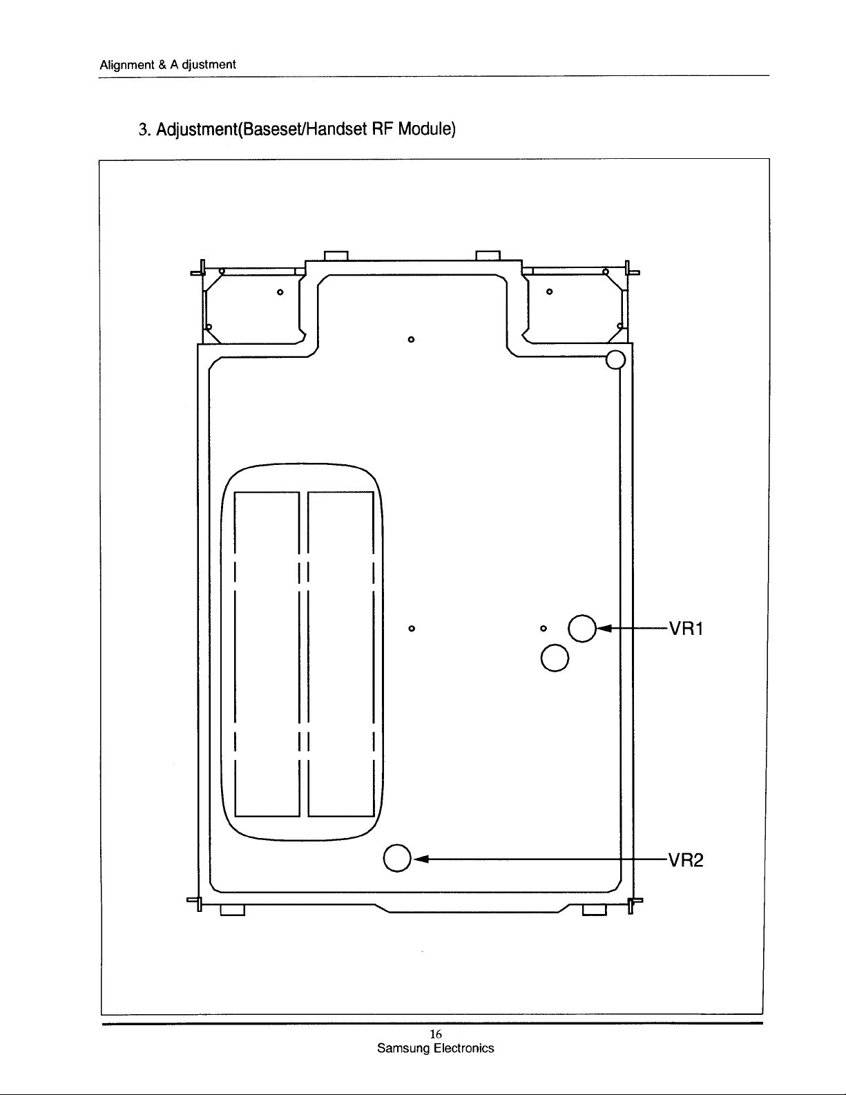
6
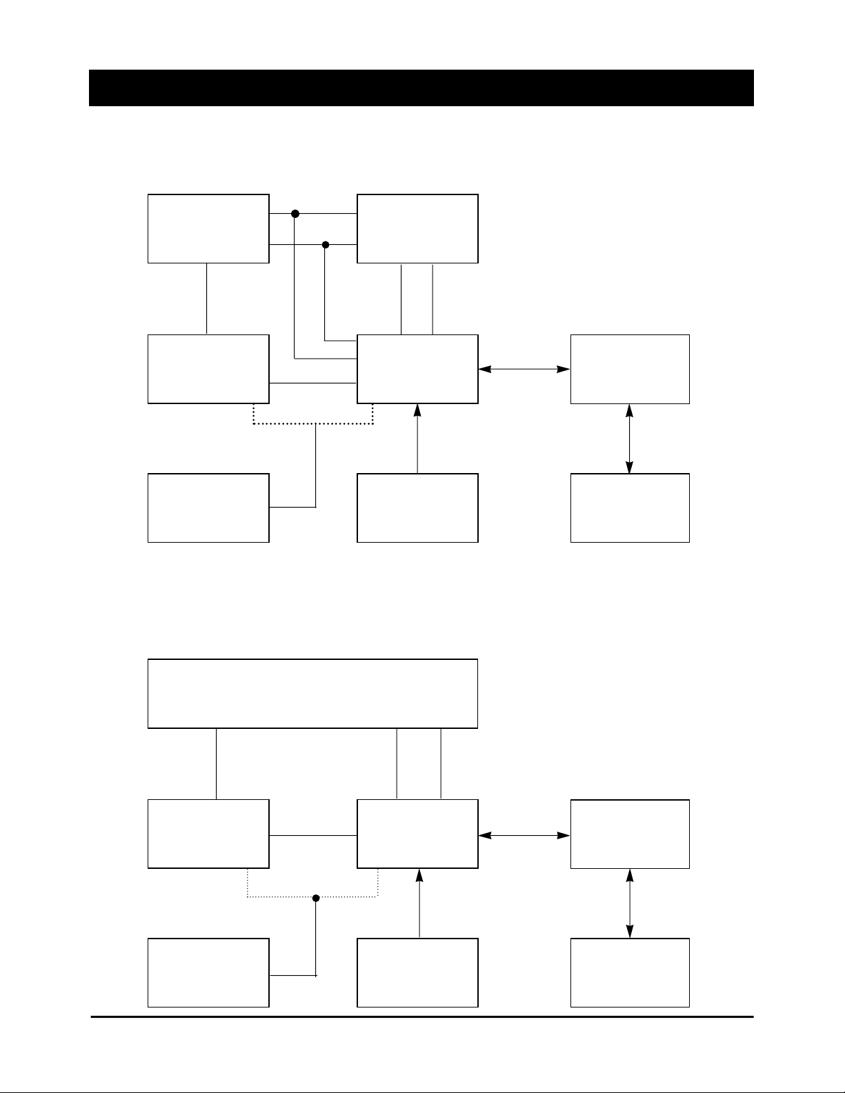
. Alignment & Adjustment
1
. Alignment (Baseset RF Module)
DECT TESTER
RF IN / OUT
AF IN
BASE RF
MODULE
OSCILLOSCOPE
2
. Alignment (Handset RF Module)
AF OUT
BASE LOGIC
ADAPTOR FOR
POWER SUPPLY
LINE
FEEDING
BOARD
IIC BUS
ALTERNATIVE
CONNECTION
CONVERTER
BOARD
PC
RF IN / OUT AF IN / OUT
RF SIGNAL
HAND RF
MODULE
OSCILLOSCOPE
POWER SUPPLY
Samsung Electronics
HAND LOGIC
BOARD
3.8 V
15
IIC BUS
ALTERNATIVE
CONNECTION
CONVERTER
BOARD
PC

Alignment & A djustment
°æ30 Hz COUNTER R98
- SELECT ACO AT PC
- ADJUT IT TO SPEC VALUE BY
PRESSING “<” OR “>” KEY AT PC
- CONNECT BASESET TO PC
- CONNECT RF MODULE TO DECT
TESTER
2 NTP 20 dBm ~ 24 dBm - KEEP PRESSING PAGING KEY AND VR1
POWER BASESET ON
- GO TO TEST MODE AT PC
- SELECT TBR6 MODE
- ADJUST TP1
3 FREQ. fo (CH 5)°æ50 kHz - SAME CONDITION WITH NO. 2 VR2
ACCURACY - ADJUST TP2
- CONNECT BASESET TO PC
- CONNECT RF MODULE TO DECT
TESTER
- KEEP PRESSING PAGING KEY AND
POWER BASESET ON PIN 42
4 Vref 2 V - GO TO TEST JIG MODE OF U10
- SELECT RVREF AT PC
- MEASURE THE VOLTAGE OF PIN 42 OF
U13 WITH VOLT METER AND ADJUST
IT TO 2.0 V BY PRESSING °ÆSHIFT°ØKEY
+°Ø<°ØOR °Æ>°ØKEY AT PC
4
. Baseset Part
°ÿfo (CH 5) = 1881.792 MHz
NO ITEM SPEC CONDITION TP
- CONNECT BASESET TO PC
- GO TO “TEST MODE” AT PC
1 X-TAL OSC. 13.824 X - CONNECT R98 TO FREQUENCY
FREQUENCY 10
6
17
Samsung Electronics

Component Pin Array
°æ30 Hz COUNTER C137
- SELECT ACO AT PC
- ADJUST IT TO SPEC VALUE BY
PRESSING “<” OR “>” KEY AT PC
- CONNECT RF MODULE TO DECT
TESTER
- INPUT PARI NUMBER TO TESTER
2 NTP 20 dBm ~ 24 dBm - GO TO TEST MODE BY PRESSING VR1
‘POWER’ KEY + ‘F’ KEY AT POWER
OFF MODE
- GO TO TBR6 MODE BY PRESSING
‘1’ KEY
- ADJUST TP1
3 FREQ. fo (CH 5)°æ50 kHz - SAME CONDITION WITH NO. 2 VR2
ACCURACY - ADJUST TP2
- CONNECT HANDSET TO PC
- CONNECT RF MODULE TO DECT
TESTER
- GO TO TEST MODE BY PRESSING
‘POWER’ KEY + ‘F’ KEY AT POWER
OFF MODE
4 Vref 2 V - GO TO TBR6 MODE BY PRESSING PIN 42
‘1’ KEY OF U13
- GO TO TEST MODE AT PC
- SELECT RVREF
- MEASURE THE VOLTAGE OF PIN 42
OF U10 WITH VOLT METER AND
ADJUST IT TO 2.0 V BY PRESSING
°ÆSHIFT°ØKEY +°Ø<°ØOR °Æ>°ØKEY AT PC
°ÿfo (CH 5) = 1881.792 MHz
5
. Handset Part
NO ITEM SPEC CONDITION TP
- CONNECT BASESET TO PC
- GO TO “TEST MODE” AT PC
1 X-TAL OSC. 13.824 X - CONNECT R98 TO FREQUENCY
FREQUENCY 10
6
18
Samsung Electronics

7
°ÿBlind Slot : The Slot Before The Active Slot.
°ÿREF CLK : In case of Baseset, It is oscillated continuously.
Blind Slot
-
-
-
Low
-
High
PLL Data
PLL CLK
Low
CLK
-
High
-
-
High
Level Low
STATUS
. Trouble Shooting
1
. Trouble Shooting of RF Module
Check Points
of U10 for
H/S and B/S
Idle Slot
T_ENABLE
(PIN4)
T_PWR_RMP
(PIN5)
T_GMSK
(PIN7)
VCO_BND_SW
(PIN8)
SYNTH_LOCK
(PIN9)
S_ENABLE
(PIN10)
S_DATA
(PIN11)
S_CLK
(PIN12)
S_PWR
(PIN13)
REF_CLK
(PIN14)
VDD_RF
(PIN16)
SLICE_CTRL
(PIN18)
R_DATAP
(PIN20)
R_DATAM
(PIN21)
R_ENABLE
(PIN22)
RSSI_AN
(PIN23)
-
-
-
Low
-
Low
-
-
High
-
-
High
-
-
High
Level
Low
Rx
Active Slot
-
-
-
Low
2.9 V
Low
-
-
Low
CLK
2.9 V
Low For
Short Time
Demodulated
Output Signal
Approximately
1.4 V
Low
Level High
(Over 1 V)
Idle Slot
High
Low
High
High
-
Low
-
-
Low
-
-
-
-
-
-
-
Tx
Blind Slot
High
Low
High
High
-
High
PLL Data
PLL CLK
Low
CLK
-
-
-
-
-
-
Active Slot
High
High
Transmit
Data
High
2.9 V
Low
-
-
Low
CLK
2.9 V
-
-
-
-
-
Samsung Electronics
19
Trouble Shooting
20
Samsung Electronics
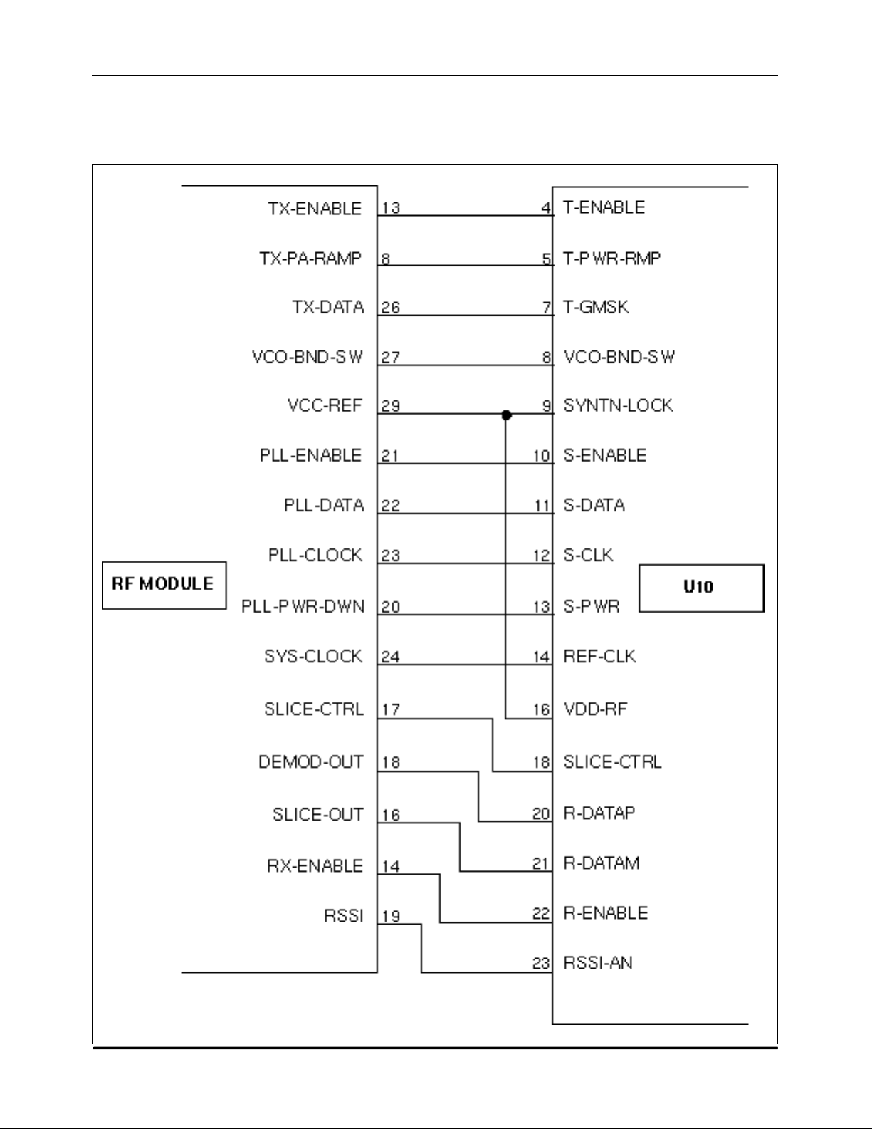
2
. Base/Remote connections between RF Module and U
10
3
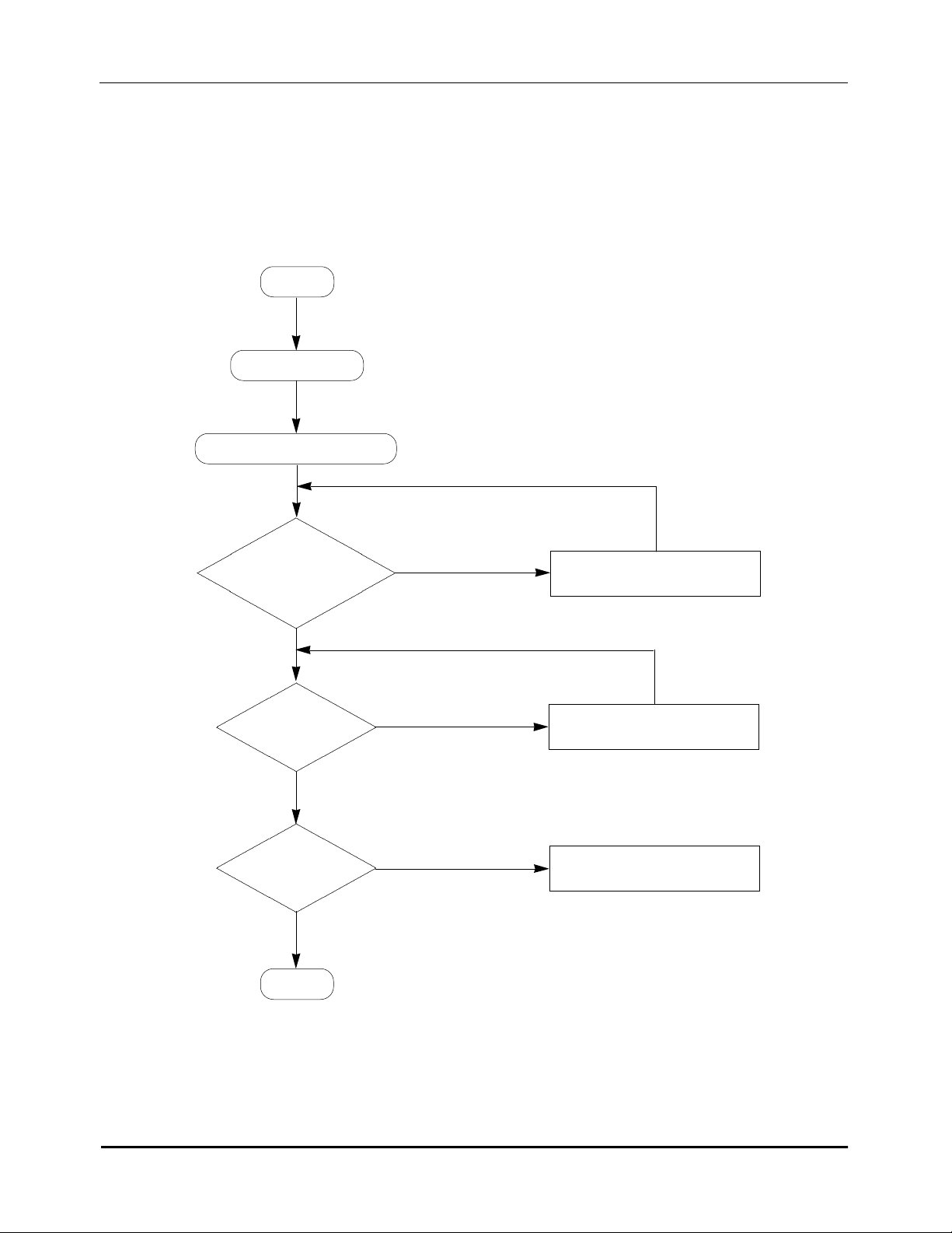
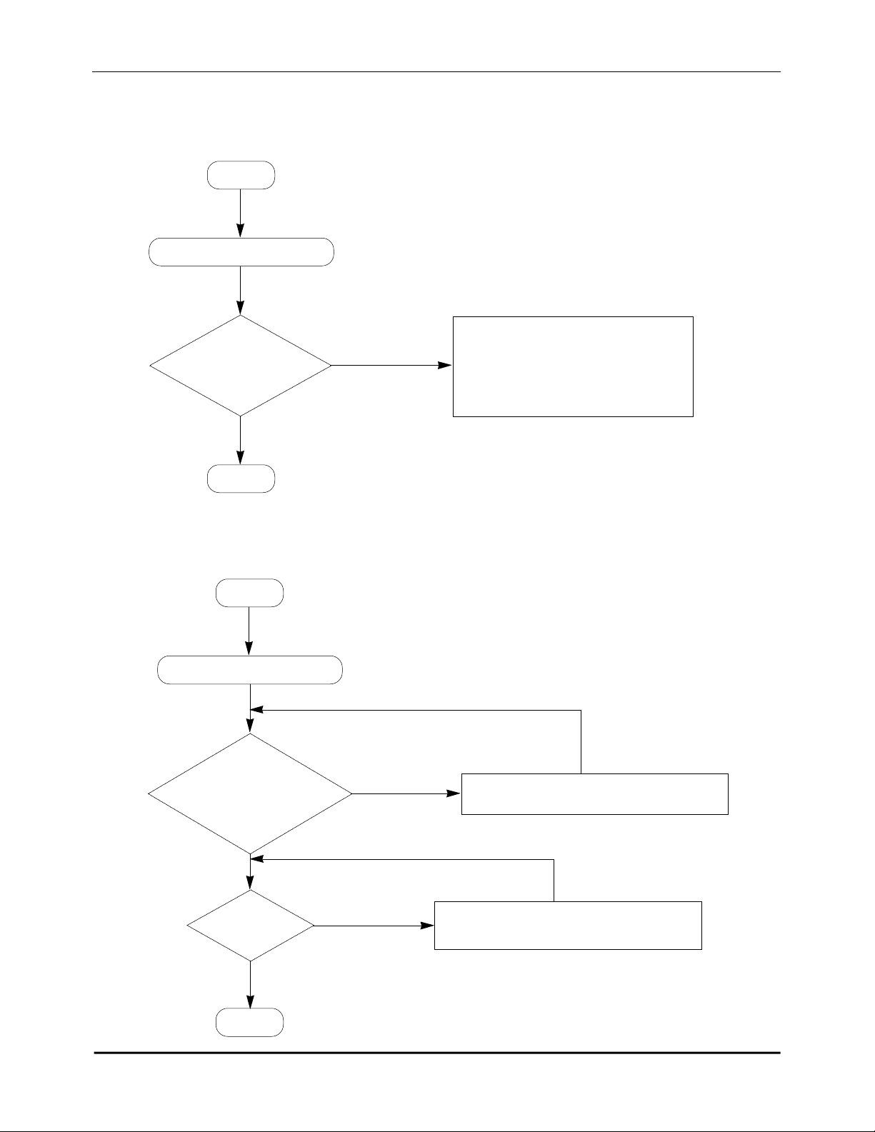
. Trouble Shooting of Handset Logic
3-1
. Power Problem
HL1
NO WORKING
POWER PROBLEM
Trouble Shooting
BATT
VOLTAGE
> 3.4 V
Y E S
PIN 4 of
U14 is 3.3 V
Y E S
U10 WORKS
Y E S
OK
N O
N O
N O
CHARGE FULLY
CHECK U14,Q15 and U11
U10 PROBLEM
21
Samsung Electronics
Trouble Shooting
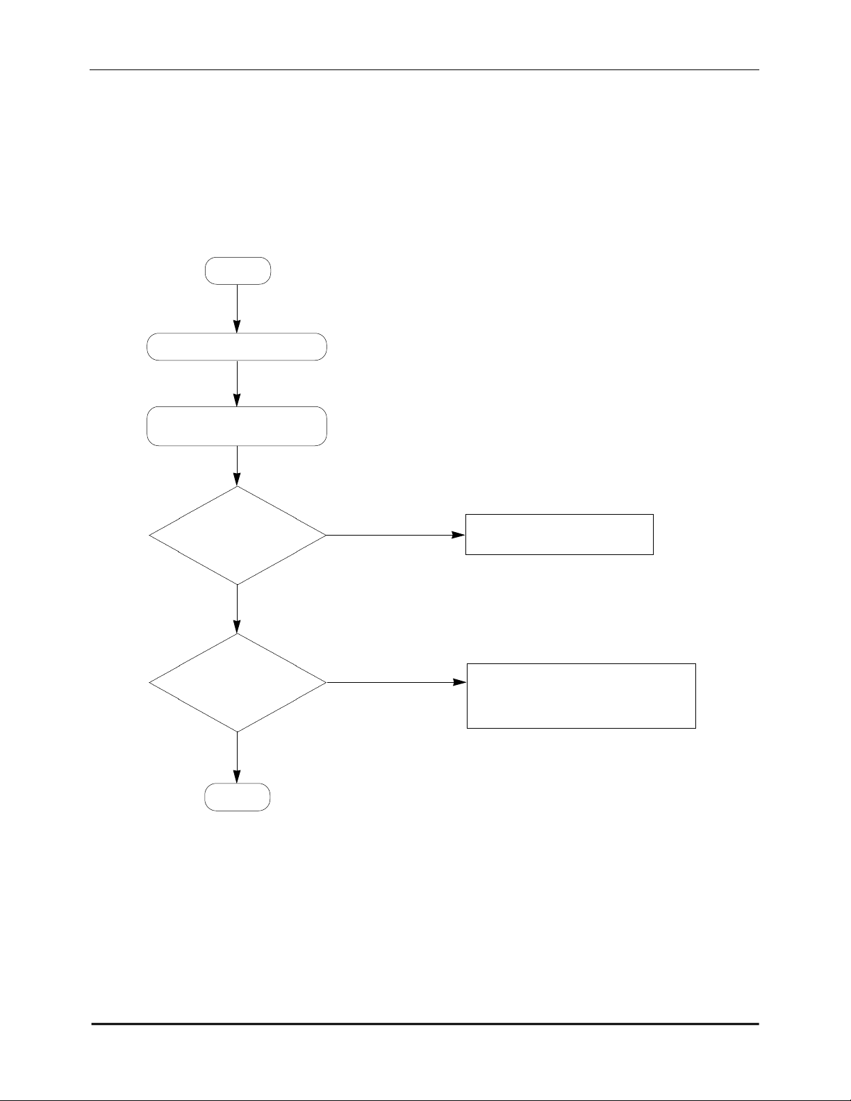
3-2. No RX Audio
LOGIC/HARDWARE
HL2
NO AUDIO (RX)
PROBLEM
AF SIGNAL
is FOUND AT PIN45,46
of U10
Y E S
AF SIGNAL
is FOUND THROUGH
THE RECEIVER
UNIT
Y E S
OK
N O
N O
GOTO RF MODULE
1. CHECK THE RECEIVER UNIT
2. CHECK COMPONENTS
AND PATTERNS
22
Samsung Electronics
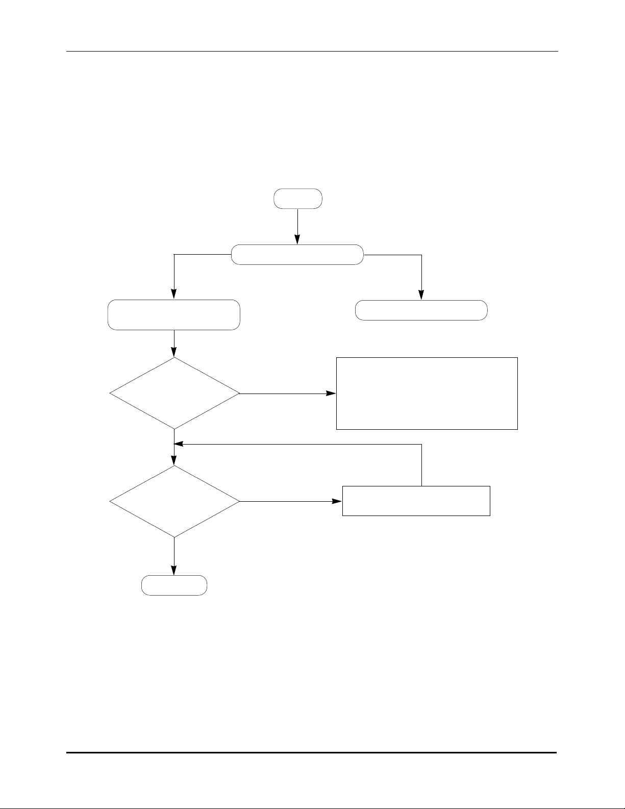
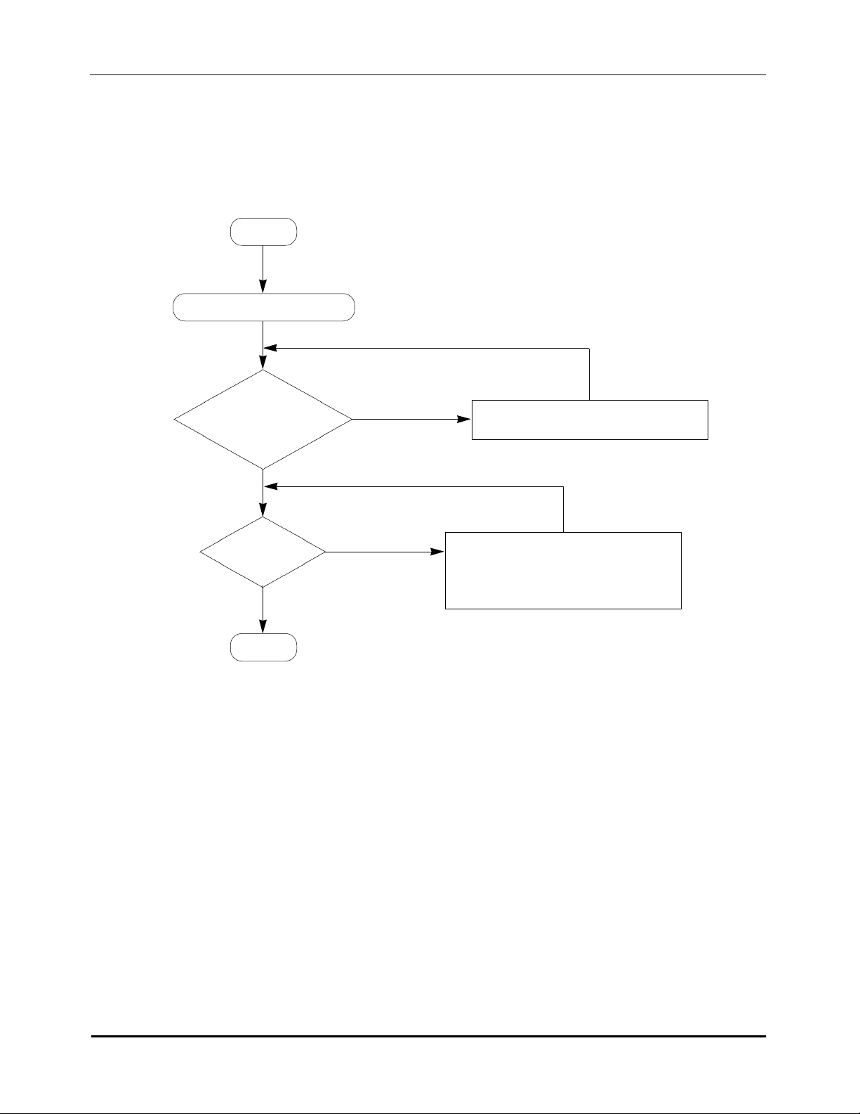
3-3. No TX Audio
Trouble Shooting
HL3
NO AUDIO (TX)
LOGIC/HARDWARE
PROBLEM
AF SIGNAL is
FOUND AT PIN39,40
of U10
Y E S
AUDIO DATA
is FOUND AT
PIN 70 OF U10
Y E S
OK
N O
N O
RF MODULE PROBLEM
1. CHECK MIC PERFORMANCE
2. CHECK MIC BIAS
3. CHECK COMPONENTS AND
PATTERNS
CHECK U10
23
Samsung Electronics
Trouble Shooting
3-4. No Key Action
HL4
NO KEY ACTION
KEY-SCAN is OK
AT EACH MATRIX
Y E S
N O
1. CHECK EACH CONNECTION
2. CHECK KEY-SCAN STATUS
FROM U10
3. CHECK THE RUBBER is OK
OK
3-5. No Display
HL5
NO DISPLAY
CONNECTIONS of
VDD, SDA, SCL
AND C131 AROUND
LCD
Y E S
N O
MAKE THE CONNECTIONS CORRECT
LCD is OK
OK
N O
24
Samsung Electronics
1. REPLACE LCD
2. CHECK SDA AND SCL PATTERNS
3-6. No Beeptone / No Ring
HL6
NO BEEPTONE, BELL
Trouble Shooting
U10 GENERATES
SIGNAL AT
PIN61,62
Y E S
BUZZER is OK
OK
N O
N O
CHECK U10
1. REPLACE BUZZER
2. CHECK PATTERNS AND
AROUND COMPONENTS
25
Samsung Electronics
 Loading...