

Page 1
Owner’s Instructions
SPL4225
Page 2

Warning! Important Safety Instructions
CAUTION: TO REDUCE THE RISK OF ELECTRIC SHOCK, DO NOT REMOVE COVER (OR BACK). NO USER
SERVICEABLE PARTS INSIDE. REFER SERVICING TO QUALIFIED SERVICE PERSONNEL.
This symbol indicates high voltage is present inside. It is dangerous to make any kind of contact
with any inside part of this product.
This symbol alerts you that important literature concerning operation and maintenance has been
included with this product.
Note to CATV system installer: This reminder is provided to call CATV system installer's attention to Article 820-40 of the National Electrical Code (Section 54 of Canadian Electrical Code, Part I), that provides
guidelines for proper grounding and, in particular, specifies that the cable ground shall be connected to the
grounding system of the building as close to the point of cable entry as practical.
Caution: FCC/CSA regulations state that any unauthorized changes or modifications to this equipment may
void the user's authority to operate it.
Caution: To prevent electric shock, match the wide blade of plug to the wide slot, and fully insert the plug.
Attention: pour eviter les chocs electriques, introduire la lame le plus large de la fiche dans la borne corre-
spondante de la prise et pousser jusqu'au fond.
Important: One Federal Court has held that unauthorized recording of copyrighted TV programs is an
infringement of U.S. copyright laws.
Certain Canadian programs may also be copyrighted and any unauthorized recording in whole or in part
may be in violation of these rights.
TO PREVENT DAMAGE WHICH MAY RESULT IN FIRE OR ELECTRIC SHOCK HAZARD, DO NOT EXPOSE THIS
APPLIANCE TO RAIN OR MOISTURE.
2
Page 3
Thank You for Choosing Samsung
Thank you for choosing Samsung! Your new Samsung product represents the latest in television technology. We designed it with easy-to-use on-screen menus and closed captioning capabilities, making it
one of the best products in its class. We are proud to offer you a product that will provide convenient,
dependable service and enjoyment for years to come.
Important Safety Information
Always be careful when using your Monitor. To reduce the risk of fire, electrical shock, and other
injuries, keep these safety precautions in mind when installing, using, and
maintaining your machine.
• Read all safety and operating instructions before operating your Monitor.
• Keep the safety and operating instructions for future reference.
• Heed all warnings on the Monitor and in the operating instructions.
• Follow all operating and use instructions.
• Unplug the Monitor from the wall outlet before cleaning. Use a damp cloth; do not use liquid or
aerosol cleaners.
• Never add any attachments and/or equipment without approval of the manufacturer. Such additions
can increase the risk of fire, electric shock, or other personal injury.
• Do not use the Monitor where contact with or immersion in water is a possibility, such as near bath
tubs, sinks, washing machines, swimming pools, etc.
• Do not place the Monitor on an unstable cart, stand, tripod, bracket,
table, or floor where it can fall. A falling Monitor can cause serious
injury to a child or adult, and serious damage to the appliance. Use
only with a cart, stand, tripod, bracket, or table recommended by the
manufacturer or sold with the Monitor. Follow the manufacturer's
instructions when mounting the unit, and use a mounting accessory
recommended by the manufacturer. Move the Monitor and cart with
care. Quick stops, excessive force, and uneven surfaces can make the
unit and cart unsteady and likely to overturn.
•Provide ventilation for the Monitor. The unit is designed with slots in the cabinet for ventilation to protect it from overheating. Do not block these openings with any object, and do not place the Monitor
on a bed, sofa, rug, or other similar surface. Do not place it near a radiator or heat register. If you
place the Monitor on a rack or bookcase, ensure that there is adequate ventilation and that you've
followed the manufacturer's instructions for mounting.
• Operate your Monitor only from the type of power source indicated on the marking label. If you are
not sure of the type of power supplied to your home, consult your appliance dealer or local power
company.
• Use only a grounded or polarized outlet. For your safety, this Monitor is equipped with a polarized
alternating current line plug having one blade wider than the other. This plug will fit into the power
outlet only one way. If you are unable to insert the plug fully into the outlet, try reversing the plug. If
the plug still does not fit, contact your electrician to replace your outlet.
3
Page 4

•Protect the power cord. Power supply cords should be routed so that they won’t be walked on or pinched
by objects placed on or against them. Pay particular attention to cords at plugs, convenience receptacles, and the point where they exit from the unit.
• Unplug the Monitor from the wall outlet and disconnect the antenna or cable system during a lightning
storm or when left unattended and unused for long periods of time. This will prevent damage to the unit
due to lightning and power-line surges.
•Avoid overhead power lines. An outside antenna system should not be placed in the vicinity of overhead
power lines or other electric light or power circuits or where it can fall into such power lines or circuits.
When installing an outside antenna system, be extremely careful to keep from touching the power lines
or circuits. Contact with such lines can be fatal.
• Do not overload the wall outlet or extension cords. Overloading can result in fire or electric shock.
• Do not insert anything through the openings in the unit, where they can touch dangerous voltage points
or damage parts. Never spill liquid of any kind on the Monitor.
•Ground outdoor antennas. If an outside antenna or cable system is connected to the Monitor, be sure the
antenna or cable system is grounded so as to provide some protection against voltage surges and builtup static charges. Section 810 of the National Electrical Code, ANSI/NFPA No.70-1984, provides information about proper grounding of the mast and supporting structure, grounding of the lead-in wire to an
antenna discharge unit, size of grounding conductors, location of antenna discharge unit, connection to
grounding electrodes, and requirements for the grounding electrode.
• Do not attempt to service the Monitor yourself. Refer all servicing to qualified service personnel. Unplug
the unit from the wall outlet and refer servicing to qualified service personnel under the following conditions:
- when the power-supply cord or plug is damaged
- if liquid has been spilled on the unit or if objects have fallen into the unit
- if the Monitor has been exposed to rain or water
- if the Monitor does not operate normally by following the operating instructions
- if the Monitor has been dropped or the cabinet has been damaged
- when the Monitor exhibits a distinct change in performance
• If you make adjustments yourself, adjust only those controls that are covered by the operating instructions. Adjusting other controls may result in damage and will often require extensive work by a qualified
technician to restore the Monitor to normal.
• When replacement parts are required, be sure the service technician uses replacement parts specified by
the manufacturer or those that have the same characteristics as the original part. Unauthorized substitutions may result in additional damage to the unit.
• Upon completion of any service or repairs to this Monitor, ask the service technician to perform safety
checks to determine that the Monitor is in a safe operating condition.
• The PDP can properly operate within the temperature range of 32~104˚F and humidity 80%.
Do not use in a hot and humid place. within the temperature range of
• Before moving the PDP equipped with speakers, separate the speakers from the PDP.
If you move the PDP holding the speakers, it may result in a detachment of the PDP and cause any
damage to the PDP and other personal injury.
4
Page 5

FCC Information
User Instructions
The Federal Communications Commission Radio
Frequency Interference Statement includes the following warning:
NOTE: This equipment has been tested and found
to comply with the limits for a Class B digital
device, pursuant to part 15 of the FCC Rules.
These limits are designed to provide reasonable
protection against harmful interference in a residential installation.
This equipment generates, uses and can radiate
radio frequency energy and, if not installed
and used in accordance with the instructions, may
cause harmful interference to radio communications. However, there is no guarantee that interference will not occur in a particular installation. If
this equipment does cause harmful interference to
radio or television reception, which can be determined by turning the equipment off and on, the
user is encouraged to try to correct the interference by one or more of the following measures.
User Information
Changes or modifications not expressly approved
by the party responsible for compliance could
void the user’s authority to operate the equipment.
If necessary, consult your dealer or an experienced radio/television technician for additional
suggestions. You may find the booklet called How
to Identify and Resolve Radio/TV Interference
Problems helpful. This booklet was prepared by
the Federal Communications Commission. It is
available from the U.S. Government Printing
Office, Washington, DC 20402, Stock Number
004-000-00345-4 .
Warning
This is a Class B product. In a domestic environment this product may cause radio interference in
which case the user may be required to take adequate measures.
User must use shielded signal interface cables to
maintain FCC compliance for the product.
Declaration of conformity for products marked
with FCC Logo. This device complies with Part 15
of the FCC Rules. Operation is subject to the following two conditions:
(1) this device may not cause harmful interference,
and
(2) this device must accept any interference
received, including interference that may
cause undesired operation.
The party responsible for product compliance:
SAMSUNG ELECTRONICS CO., LTD
America QA Lab of Samsung
3351 Michelson Drive, Suite #290,
Irvine, CA 92612, U.S.A
Tel) 949-975-7310
Fax) 949-975-7328
Provided with this monitor is a detachable power
supply cord with IEC320 style terminations.
It may be suitable for connection to any UL Listed
personal computer with similar configuration.
Before making the connection, make sure the voltage rating of the computer convenience outlet is
the same as the monitor and that the ampere rating of the computer convenience outlet is equal to
or exceeds the monitor voltage rating.
For 110 Volt applications, use only UL Listed
detachable power cord with NEMA configuration
5-15P type (parallel blades) plug cap. For 230
Volt applications use only UL Listed Detachable
power supply cord with NEMA configuration
6015P type (tandem blades) plug cap.
IC Compliance Notice
This Class B digital apparatus meets all requirements of the Canadian Interference-Causing
Equipment Regulations of ICES-003.
Notice de Conformité IC
Cet appareil numérique de Classe B respecte
toutes les exigences du Règlement ICES-003 sur
les équipements produisant des interférences au
Canada.
European Notice
Products with the CE Marking comply with both
the EMC Directive (89/336/EEC), (92/31/EEC),
(93/68/EEC) and the Low Voltage Directive
(73/23/EEC) issued by the Commission of the
European Community. Compliance with these
directives implies conformity to the following European Norms:
• EN55022 : 1998 Class B
• EN55024 : 1998
• EN61000-3-2 : 1995
• EN61000-3-3 : 1995
5
Page 6

User Instructions
Screen Image retention
Do not display a still image (such as on a video game or when hooking up a PC to this Monitor) on the
plasma monitor panel for more than several minutes as it can cause screen image retention. This image
retention is also known as “screen burn”. To avoid such image retention, refer to page 28 of this manual to
reduce the degree of brightness and contrast of this screen when displaying a still image.
Cell Defect
The plasma display panel consists of fine cells. Although the panels are produced with more than 99.9
percent active cells, there may be some cells that do not produce light or remain lit.
Altitude
The PDP will not operate normally at altitudes above 6500 ft.
Warranty
Warranty Period: One year starting from the purchase of your Monitor.
Warranty does not cover any damage caused by image retention.
6
Page 7

Table of Contents
Setup
Your New Plasma Display Panel ........................10
Remote Control Buttons ....................................12
Wall Installation Instructions ..............................14
Turning the PDP On and Off..............................18
Connection (Connecting Speakers /
Receiver)
Connecting Speakers ......................................22
Connecting a VCR/Cable Box ..........................23
Connecting a DVD ..........................................24
Connecting a Set-Top Box ................................25
Picture Control
Customizing the Picture ....................................28
Using Automatic Picture Settings ........................29
Viewing the Picture-in-Picture ............................30
Connecting PC and Operation
Connecting to a PC..........................................46
Adjusting the PC Screen ..................................50
Changing the Position of the Image....................51
Changing the Size of the Image ........................52
Enlarging the Image (Zoom)..............................53
Moving the Zoom Picture ..................................54
Picture Quality Adjustment ................................55
Information ....................................................58
Power Saver (PC mode only) ............................59
Function Description
Selecting a Menu Language..............................62
Setting the Multi Control ..................................63
Using the Key Lock ..........................................64
Setting up Your Remote Control ........................65
Changing the Screen Size ................................33
Freezing the Picture..........................................34
Sound Control
Customizing the Sound ....................................36
Using Automatic Sound Settings ........................37
Using the Surround ........................................38
Time Setting
Setting the Clock ............................................40
Setting the Sleep Timer ....................................41
Setting the Timers ............................................42
Appendix
Troubleshooting ..............................................68
Care and Maintenance ....................................69
Specifications..................................................70
7
Page 8

Page 9
PLASMA DISPLAY PANEL
Setup
Your New Plasma Display Panel ....................................................10
Remote Control Buttons ................................................................12
Wall Installation Instructions ..........................................................14
Turning the PDP On and Off ..........................................................18
Page 10
Your New Plasma Display Panel
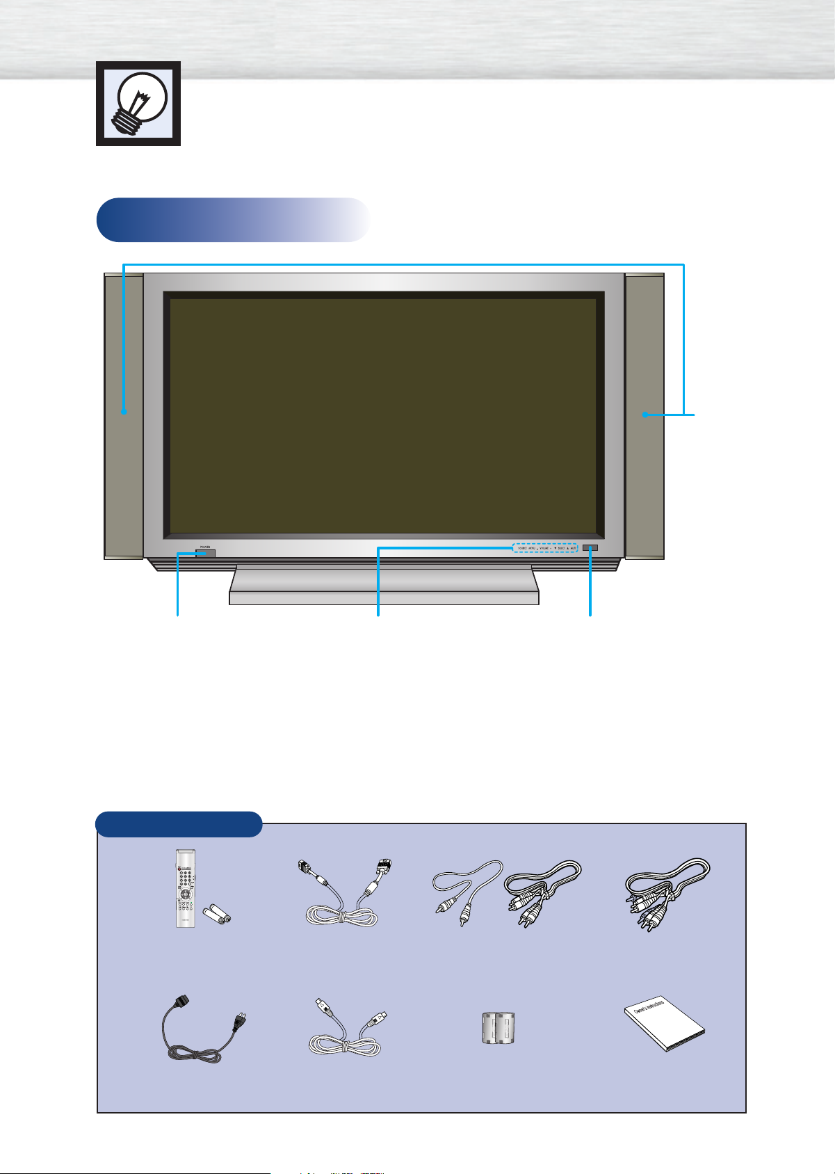
Front Panel
Speakers
POWER
Press to turn
the PDP on
and off.
Checking Accessories
Remote Control/
AAA Batteries
SOURCE, MENU, VOLUME (-,+),
SELECT (▼,▲), MUTE
PC Cable
Remote Control Signal Receiver
Aim the remote control towards
this spot on the Monitor.
Video CableVideo/Audio Cables
10
Power Cord
S-VIDEO Cable Ferrite Cores(2EA)
Owner’s Instructions
Page 11

Rear Panel
ŒExternal Speaker Out jacks
Connect external speakers.
´PC(RGB) Input jack (15pin)
Connect to the video output jack on your PC.
ˇComponent Video Input jacks ( Y/Pb/Pr)
Component 1 inputs are for 480i/480p.
Component 2 inputs are for 480p/720p/
1080i.
¨Video Input jack
Connect a video signal from external sources
such as VCRs or DVD players.
ˆS-Video Input jack
Connect a S-Video signal from an S-VHS VCR
or DVD player.
ØAudio Input (Video/Component1/2/PC(RGB))
jacks
Connect a audio signal from external sources
such as VCRs, PC or DVD players.
∏Service Jack
Connect the RS-232C input jack to your PC.
”Power Input jack
Connect the supplied power cord.
11
Page 12

Remote Control Buttons
Remote Control
ŒPower button
Turns the PDP on and off.
´Number buttons
ˇDisplay button
Press to display information on the PDP screen.
¨Menu button
Displays the main on-screen menu.
ˆCH (Channel) and VOL (Volume) buttons
Channel and Volume buttons are used for selecting
menu items in the menu mode.
Flip the cover open
in the arrow direction.
ØMute button
Press to mute the PDP sound.
∏P.Mode button
Adjust the PDP picture by selecting one of the preset
factory settings (or select your personal, customized
picture settings.)
”Aspect button
Press to change the screen size.
’Mode button
Selects a target device to be controlled by the Samsung remote control (ie., VCR, Cable, or DVD players).
˝Clock Display button
Press to display clock on the PDP screen.
ÔSource button
Press to display all of the available video sources
(ie., Video, S-Video, Component1, Component2,
PC(RGB)).
Joystick button
Use to highlight on-screen menu items and change
menu values.
ÒStill button
Press to pause the current screen.
ÚPIP button
Activates picture in picture.
ÆSource selection buttons
Press to directly select Video, S-Video, Component1,
Component2 or PC(RGB).
12
Page 13
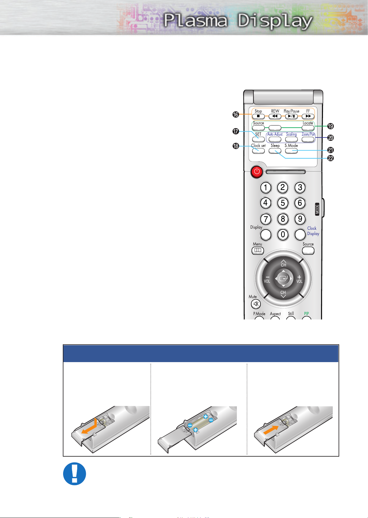
ıVCR control buttons
Controls VCR tape functions: Stop, Rewind,
Play/Pause, Fast Forward.
˜SET button
Used during setup of this remote control, so that it will
work compatibly with other devices (VCR, cable box,
DVD, etc.)
¯Clock set button
Press to set clock.
˘PIP control buttons
Source : Press to select one of the available signal
sources for the PIP window.
S.Sel : Press to select the Audio (PIP or Main).
Locate : Press to move the PIP window on the screen.
¿PC control buttons
Auto Adjust
Scaling
Zoom/Pan
¸S.Mode button
Adjust the PDP sound by selecting one of the preset
factory settings (or select your personal, customized
sound settings.)
˛Sleep button
Press to select a preset time interval for automatic
shutoff.
S.Sel
Slide the back cover
1
to open the battery
compartment of the
remote control
Remote Control Operation Range.
You can use your remote control within a distance of 23 feet and an angle of 30 degrees
from the left and right sides of the remote control receiver of the monitor.
Installing the Batteries in Your Remote Control
Install two AAA size batter-
2
ies. Make sure to match the
“+” and “-” ends of the batteries with the diagram
inside the compartment.
3
Slide the cover back into
place.
13
Page 14
Wall Installation Instructions
Installation Notes
Do not install the PDP in any location other than vertical walls.
1
To protect the performance of the PDP and prevent problems, avoid the following
places:
2
• Do not install next to smoke and fire detectors.
• Do not install in an area subjected to vibration.
• Do not install in an area subjected to high voltage.
• Do not install near or around any heating apparatus.
Use only recommended parts and components.
3
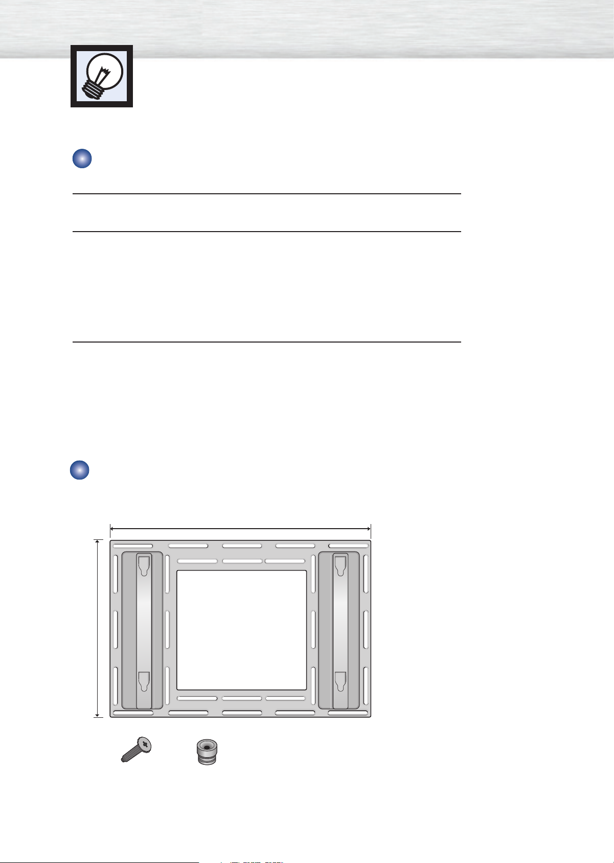
Parts (Wall attachment panel is sold separately. Check with your dealer)
Wall attachment panel
34.61 inches
24.57 inches
14
Insulation holderbolt
Page 15

Installing the Display on the Wall Attachment Panel
See the drawing of the wall attachment panel shown in page 14 to check for
the stability of the wall where the PDP is to be installed. If the wall is not
1
enough strong to support the PDP, strengthen the wall before installation.
Fix the wall attachment panel on the wall using bolts as shown in the following
figure: Fixing bolts must protrude from the wall appox. 0.6 inches.
2
Using the wall attachment panel, you may adjust the angle of the display from
0 to 20 degrees. The angle can be set in 5 stages with 5 degrees of distance
3
each, using the angle control holes on the sides of the panel.
When the angle
has been set to 5
degrees.
Angle control holes
When the angle
has been set to
15 degrees.
Continued...
When the panel
hasn't been tilted.
5 degrees of tilt
10 degrees of tilt
15 degrees of tilt
20 degrees of tilt
No tilt
15
Page 16

Remove four large screws from the rear side of the display.
4
Insert the bolts and insulation sinto the four screwholes as shown in the following figure:
5
ΠBolt
´ Insulation holder
Put the insulation rubber point protruding from the rear top of the display in
the groove on the top of the wall attachment panel. Lift up the display a little
6
bit so that the insulation rubber point at the bottom of the rear side of the
display is put in the groove at the bottom of the wall attachment panel.
(Do not lift the display with any pressure. The insulation rubber at the top may
be taken off. )
Œ
´
16
Page 17
Separating the Display from the Wall Attachment Panel
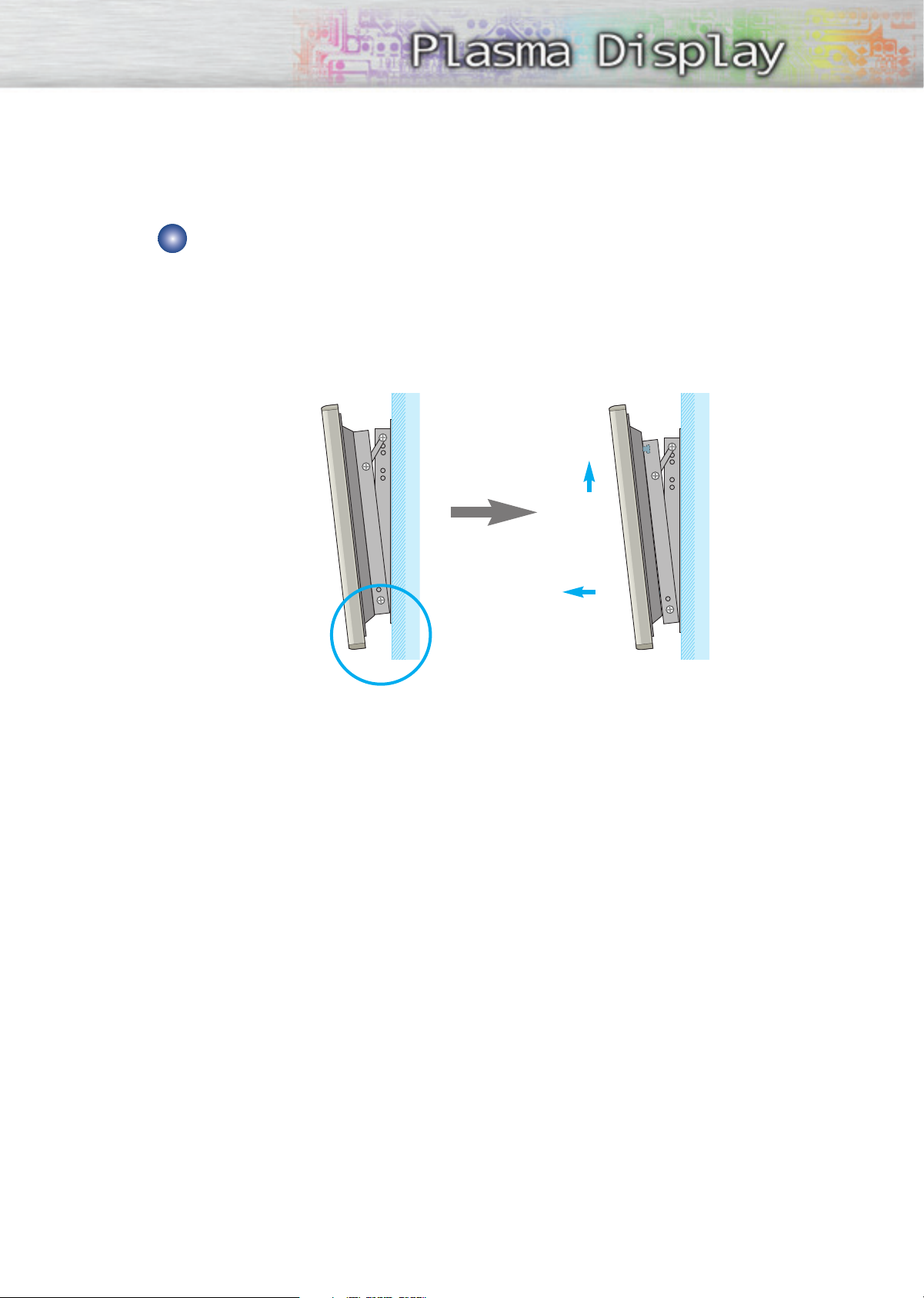
Remove the fixing bolts from both sides (left and right) of the wall attachment panel. Lift and pull the
bottom of the display a small amount, to separate the insulation holder point from the bottom of the
wall attachment panel.
Lift the display and separate the insulation holder point from the groove on top of the wall attachment
panel.
Œ
´
17
Page 18
Turning the Monitor(PDP) On and Off
Turning the Monitor(PDP) On and Off
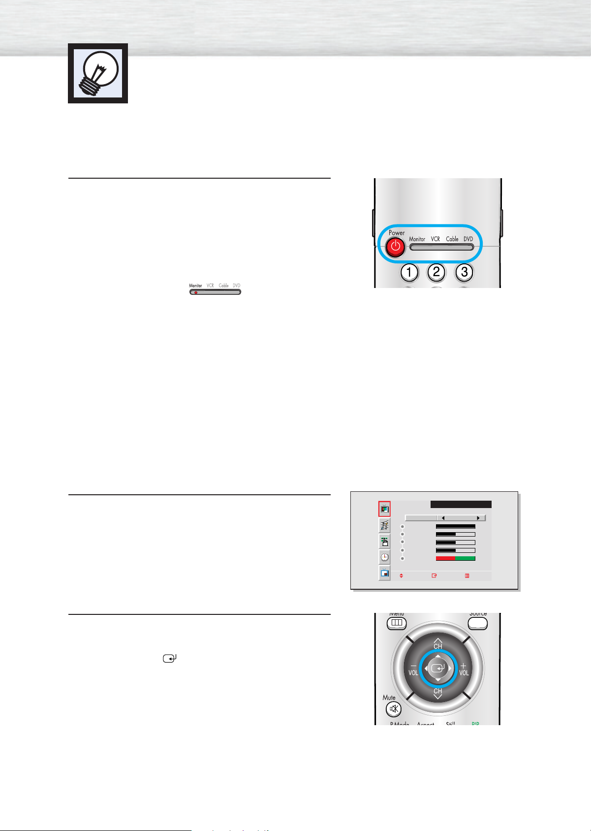
Press the Power button on the remote control.
The PDP will be turned on and you will be ready to use it’s
features.
You can also use the Power button on the front of the
PDP.
Notes:
• If your Monitor isn’t turned on when the power button is
pressed: Press the MODE button to check if the Monitor
mode has been chosen ( ).
Viewing the Menus and Displays
Your PDP has a simple, easy-to-use menu system that appears on the PDP screen. This system makes it convenient and fast to use features on the PDP. Your PDP also lets you display the status of many of your PDP’s
features.
Viewing the Menus
With the power on, press the Menu button on the
remote control. The main menu appears on the screen.
1
The Video menu is selected.
Use the joystick (up, down) button to move items in the
menu. Use the joystick (left, right) button to display,
2
change, or use the selected items.
Use the joystick ( ) button to enter items in the menu.
On screen menus disappear from the screen
automatically after about thirty seconds, or you can
press the Menu button on your remote control to exit the
menu.
Select
Contrast
Brightness
Sharpness
Color
Tint R 50
Move Enter Exit
VIDEO
Custom
100
50
50
50
G 50
18
Page 19

Displaying Status Information
Press the Display button on the remote control. The PDP will
display the Screen size, Resolution, Current time, and screen
mode.
Displaying Clock
Press the Clock Display button on the remote control.
The Current time will be displayed on the screen.
DISPLAY
Main : Video
SUB : Not Available
P.MODE : Custom
Scaling : Wide
S.MODE : Custom
Resolution : 720 X 480 60Hz
10 : 30 AM
19
Page 20

Page 21
PLASMA DISPLAY PANEL
Connections
(Connecting Speakers / Receiver)
Connecting Speakers....................................................................22
Connecting a VCR/Cable Box ......................................................23
Connecting a DVD ......................................................................24
Connecting a Set-Top Box..............................................................25
Page 22

Connecting Speakers
Speaker Audio Cable
Speaker Audio Cable
✱ External speakers MUST have a power handling capability of 7 watts minimum(impedance 8ohm).
How to Connect
Connect the speaker audio cable to the external speaker output jack on the rear of the PDP,
matching the “+” and “-” ends of the cable with the diagram on the PDP.
Connecting PDP and Speakers / Stand and Speakers
Fix the bracket onto the guide pole located on the rear
1
of speaker and fasten the screws.
After removing the three screws on the PDP, clamp
2
thespeaker and the PDP together and fasten the screws.
Guide
pole
• Connecting Speakers to Stands.
Guide
pole
22
Guide
pole
Page 23
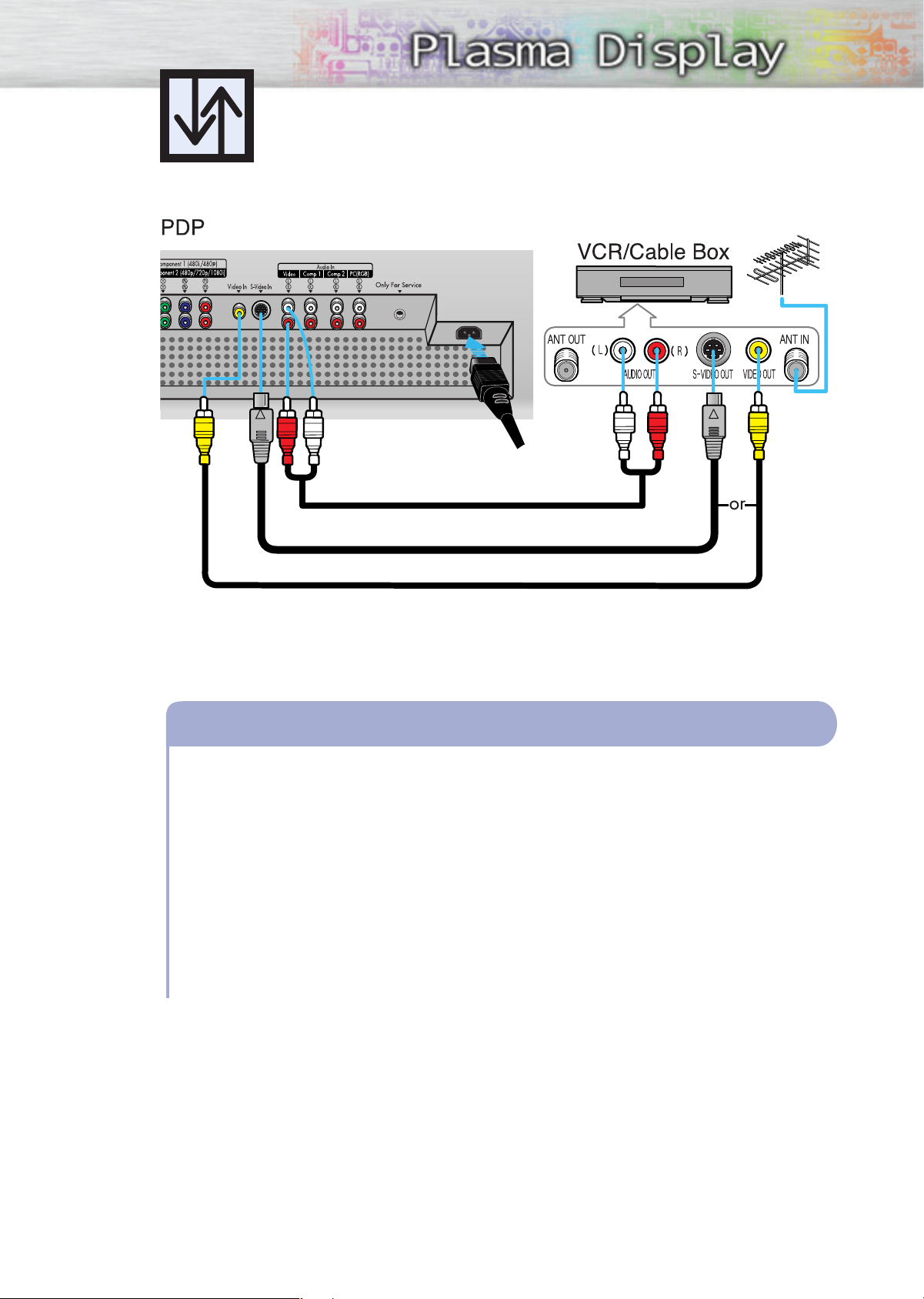
Connecting a VCR/Cable Box
Power Plug
Audio Cable
S-Video Cable
Video Cable
How to Connect
Connect Video/S-Video cable between the Video/S-Video Output jack on the VCR/Cable
1
box and the Video Input jack on the PDP.
• For better video, use an S-Video cable.
Connect an Audio cable between the Audio Output jacks on the VCR/Cable box and the
2
Audio Input jacks (Video) on the PDP.
Videotape Playback:
1. Turn on PDP and press the Video or S-Video(if S-Video jack is connected.) button on your
remote control.
2. Turn on your VCR, insert a videotape and press the Play button.
23
Page 24
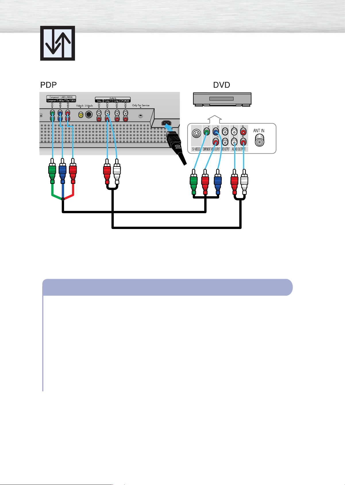
Connecting a DVD (480i/480p)
Power Plug
Video (Y, P
b
, Pr) Cable
Audio Cable
How to Connect
Connect a Video cable between the DVD Output jacks on the DVD and the Component1
1
Video Input (Y,Pb,Pr) Input jacks on the PDP.
Connect an Audio cable between the Audio Output jacks on the DVD and the Audio Input
2
jacks (Component) on the PDP .
Play to DVD:
1. Turn on PDP and press the Component button to select the Component1 mode.
2. Turn on your DVD, insert a DVD disc and press the Play button.
24
• For an explanation of Component video, see your DVD owner’s instructions.
Page 25
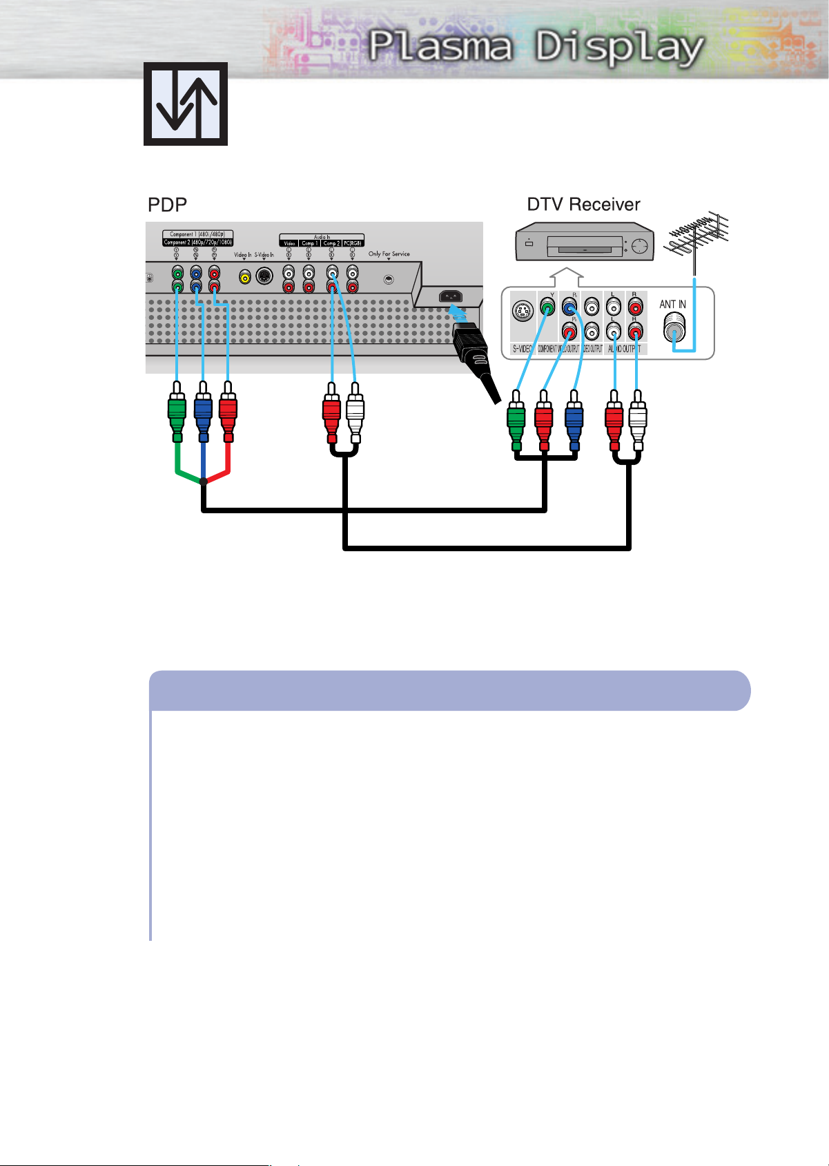
Connecting a Set-Top Box(480p/720p/1080i)
Power Plug
Video (Y, P
b
, Pr) Cable
Audio Cable
How to Connect
Connect a Video cable between the Set-Top Box (Y,Pb,Pr) Output jacks on the Set-Top Box and
1
the Component 2 Video Input (Y,Pb,Pr) Input jacks on the PDP.
Connect an Audio cable between the Audio Output jacks on the Set-T op Box and the Audio
2
Input jacks (Component) on the PDP .
To Watch DTV:
1. Turn on PDP and press the Component button to select the Component2 mode.
2. Turn on your DTV receiver.
• For an explanation of Component video, see your DTV receiver owner’s instructions.
25
Page 26

Page 27
PLASMA DISPLAY PANEL
Picture Control
Customizing the Picture ................................................................28
Using Automatic Picture Settings ....................................................29
Viewing the Picture-in-Picture..........................................................30
Changing the Screen Size ............................................................33
Freezing the Picture ......................................................................34
Page 28
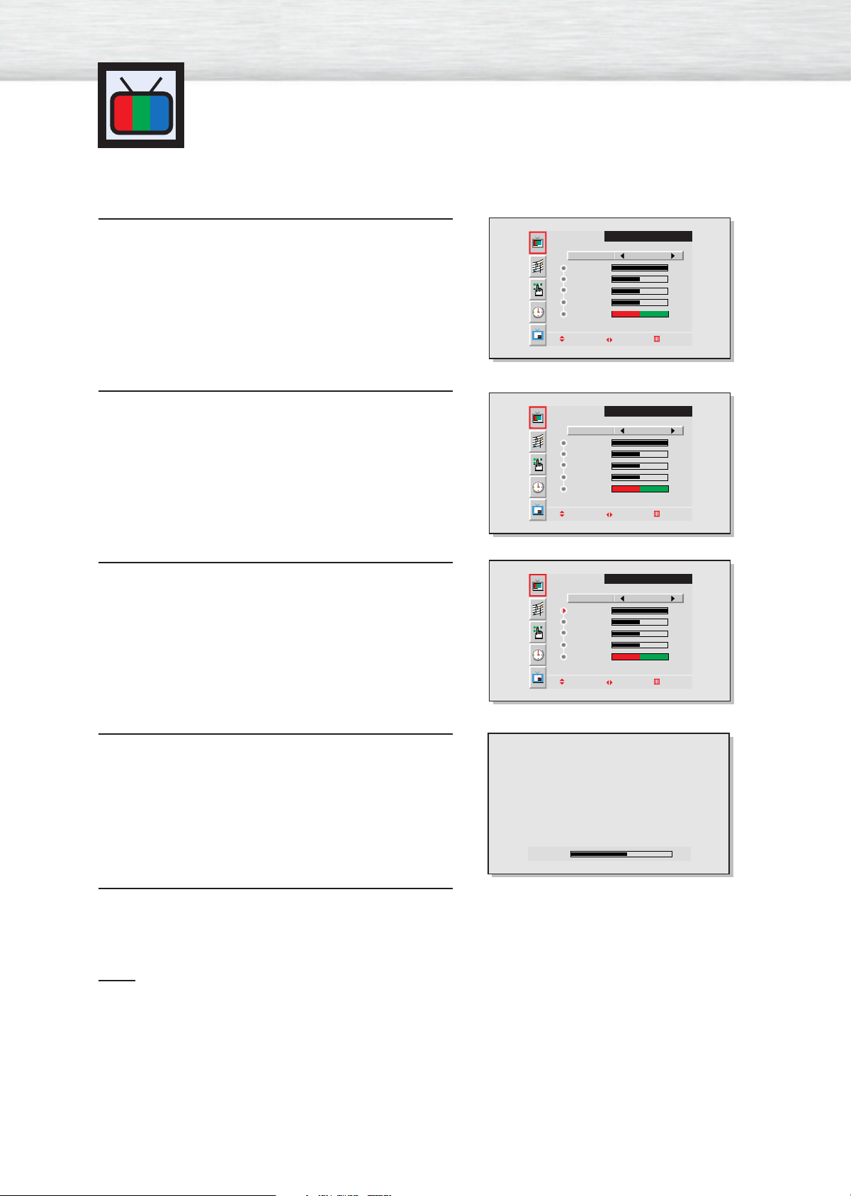
Customizing the Picture
You can use the on-screen menus to change the Brightness, Contrast, Sharpness, Color, and
Tint settings of your PDP.
Press the Menu button, then press the joystick to
enter.
1
Move the joystick left or right to select “Custom”.
You will also see the items “Contrast”, “Brightness”,
2
“Sharpness”, “Color” and “Tint”.
Move the joystick up or down to select the item you
wish to change.
3
VIDEO
Select
Contrast
Brightness
Sharpness
Color
Tint R 50
Move Adjust Exit
Select
Contrast
Brightness
Sharpness
Color
Tint R 50
Move Adjust Exit
Select
Contrast
Brightness
Sharpness
Color
Tint R 50
Custom
100
50
50
50
G 50
VIDEO
Custom
100
50
50
50
G 50
VIDEO
Custom
100
50
50
50
G 50
Move the joystick left or right to change the value of
the item.
4
Press the Menu button to exit.
5
Note
• In the PC mode, you can’t adjust the sharpness, color and tint.
Move Adjust Exit
Contrast 60
28
Page 29
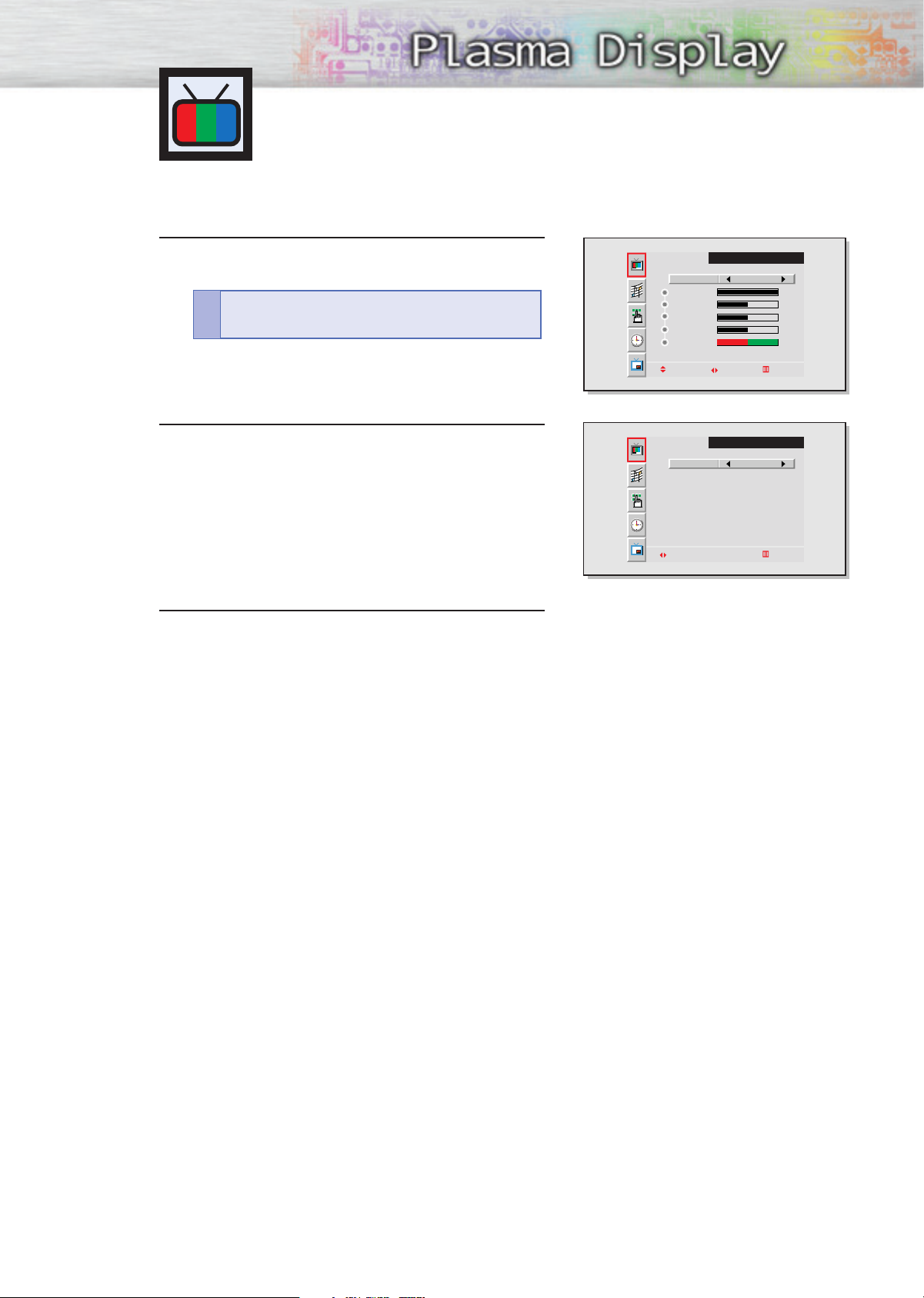
Using Automatic Picture Settings
Your PDP has automatic picture settings that allow you to adjust the video display easily.
Press the Menu button, then press the joystick to
enter.
1
Quick way to access the picture setting: Just
press “P.Mode” on the remote control.
!
Move the joystick left or right to select “Custom”,
“Standard”, “Mild”, or “Dynamic” picture setting.
2
• You can select “High,” “Middle,” “Low,” or
“Custom” in PC mode.
Press the Menu button to exit.
3
VIDEO
Select
Contrast
Brightness
Sharpness
Color
Tint R 50
Move Adjust Exit
Select Standard
select Exit
Custom
100
50
50
50
G 50
VIDEO
29
Page 30
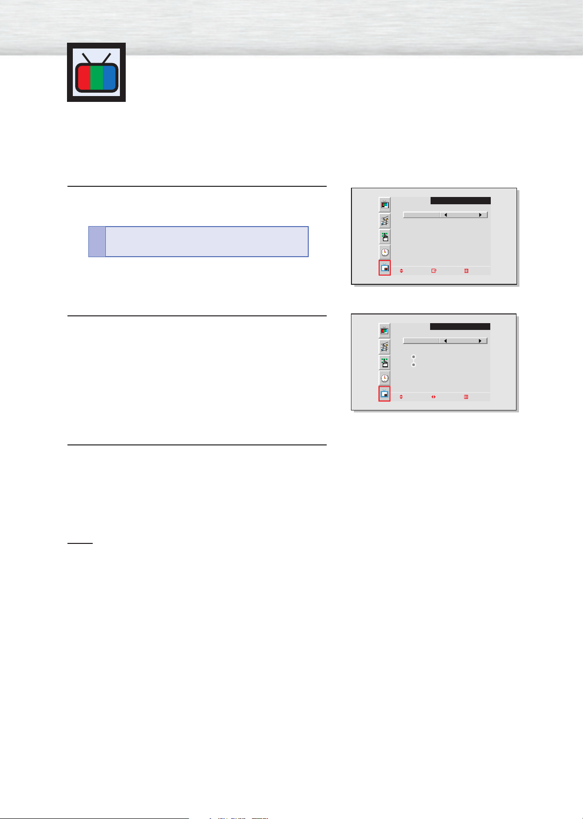
Viewing the Picture-in-Picture
Selecting the PIP Screen
Press the Menu button. Move the joystick up or down to
select “PIP”, then press the joystick to enter.
1
Quick way to access the PIP: Just press “PIP”
on the remote control.
!
Move the joystick left or right to select “On”.
The PIP image will appear in the corner of the screen.
2
Press the Menu button to exit.
3
PIP
Select Off
Move Enter Exit
PIP
Select On
Locate
Source
Move Adjust Exit
Note
• The PIP function operates in PC mode or Component2 mode only.
30
Page 31
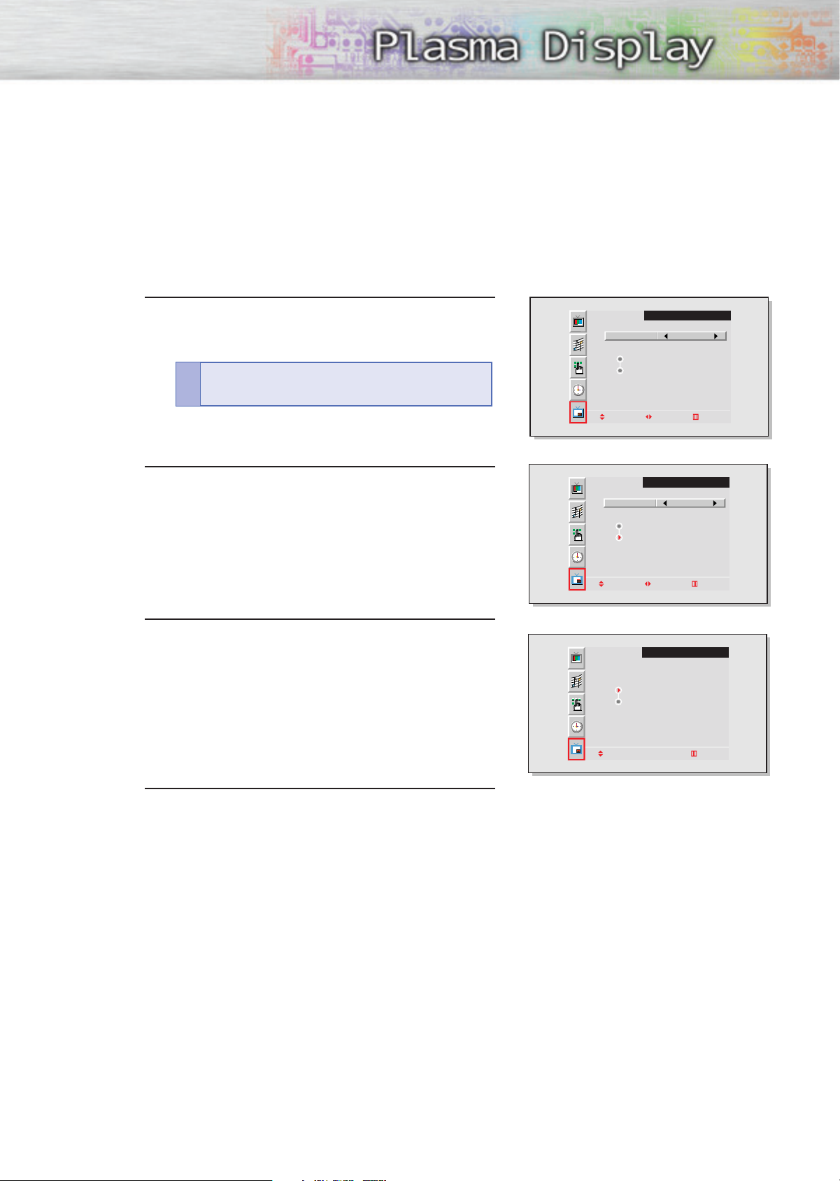
Selecting an External Signal
You can use PIP to view a signal from an external source, such as a VCR.
Press the Menu button. Move the joystick up or
down to select “PIP”, then press the joystick to
1
enter.
Quick way to access the PIP source: Just press
“Source” in the cover on the remote control.
!
Move the joystick up or down to select “Source”,
then move the joystick left or right to enter.
2
Move the joystick up or down to select an external
signal, then move the joystick left or right.
3
PIP
Select On
Locate
Source
Move Adjust Exit
PIP
Select On
Locate
Source
Move Adjust Exit
PIP
VIDEO
S-VIDEO
Press the Menu button to exit.
4
Move Exit
31
Page 32
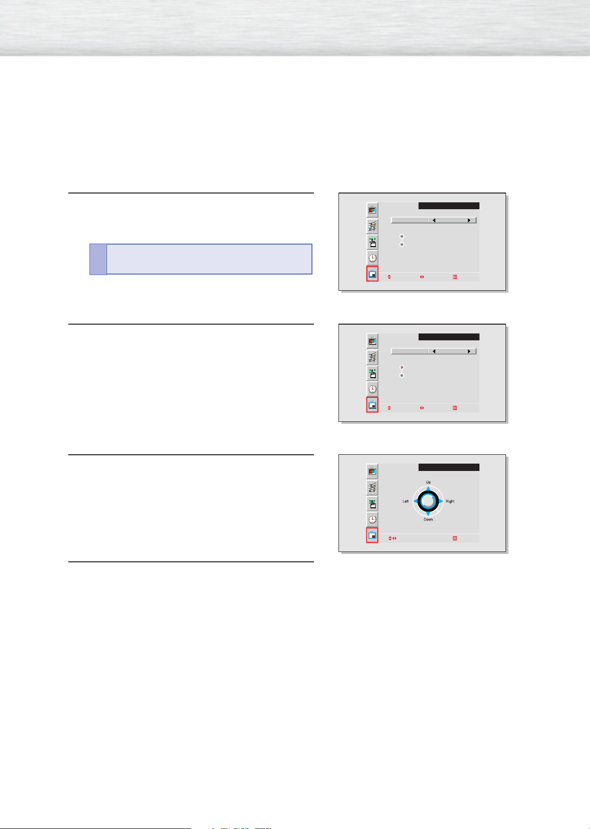
Changing the Location of the PIP Image
Press the Menu button. Move the joystick up or
down to select “PIP”, then press the joystick to
1
enter.
Quick way to access the PIP location: Just press
“Locate” in the cover on the remote control.
!
Move the joystick up or down to select “Locate”,
then move the joystick left or right to enter.
2
Move the joystick to move the PIP screen where you
want.
3
PIP
Select On
Locate
Source
Move Adjust Exit
PIP
Select On
Locate
Source
Move Adjust Exit
PIP
32
Adjust Exit
Press the Menu button to exit.
4
Page 33
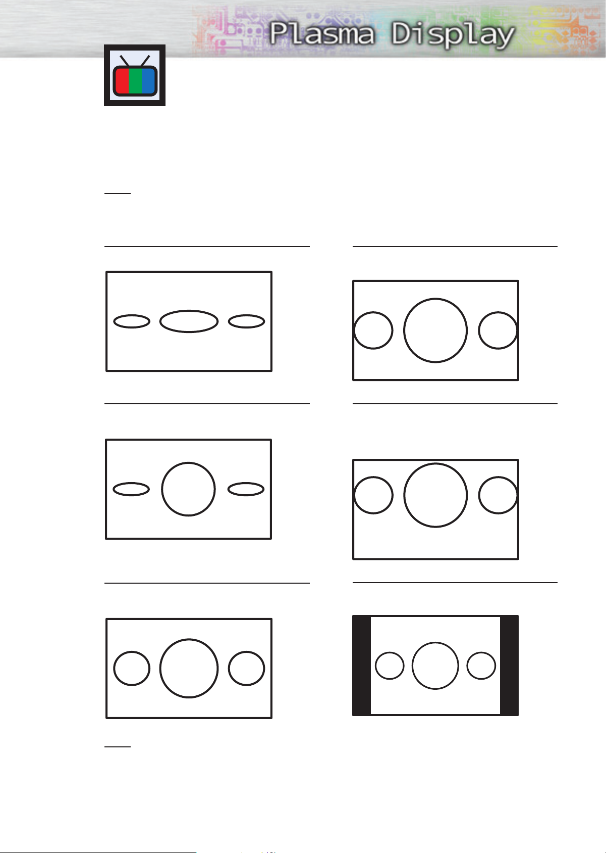
Changing the Screen Size
(When entering the Video mode)
When you press the Aspect button on the remote control, the PDP’s screen mode should appear in
sequence. The screen displays in this order: Wide, Panorama, Zoom1, Zoom2, Stretch, 4:3.
Note
• If you watch a still image or the 4:3 mode for a long time(over 2 hours), an image may be burned
onto the screen, View the monitor in Wide or Panorama mode as much as possible.
Wide
Sets the picture to 16:9 wide mode.
Panorama
Converts regular 4:3 aspect ratio screen to
widescreen.
Zoom2
Magnifies the size of the picture more than
Zoom1.
Stretch
Moves the Zoom2 picture up a little to fully
show the bottom. Use this picture size if you
want to view the Zoom2 picture along with
captions when watching movies.
Caption
Zoom1
Magnifies the picture vertically on screen.
4:3
Sets the picture to 4:3 normal mode. This is a
standard PDP screen size.
Note
• In VIDEO, S-VIDEO, and Component1 modes, all screen modes can be selected.
(Wide ➝ Panorama ➝ Zoom1 ➝ Zoom2 ➝ Stretch ➝ 4:3).
33
Page 34
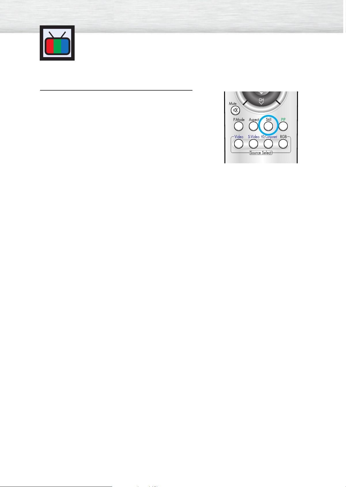
Freezing the Picture
Still
Press the Still button on the remote control to freeze a moving picture. Press again to cancel.
34
Page 35
PLASMA DISPLAY PANEL
Sound Control
Customizing the Sound ................................................................36
Using Automatic Sound Settings ....................................................37
Using the Surround ......................................................................38
Page 36
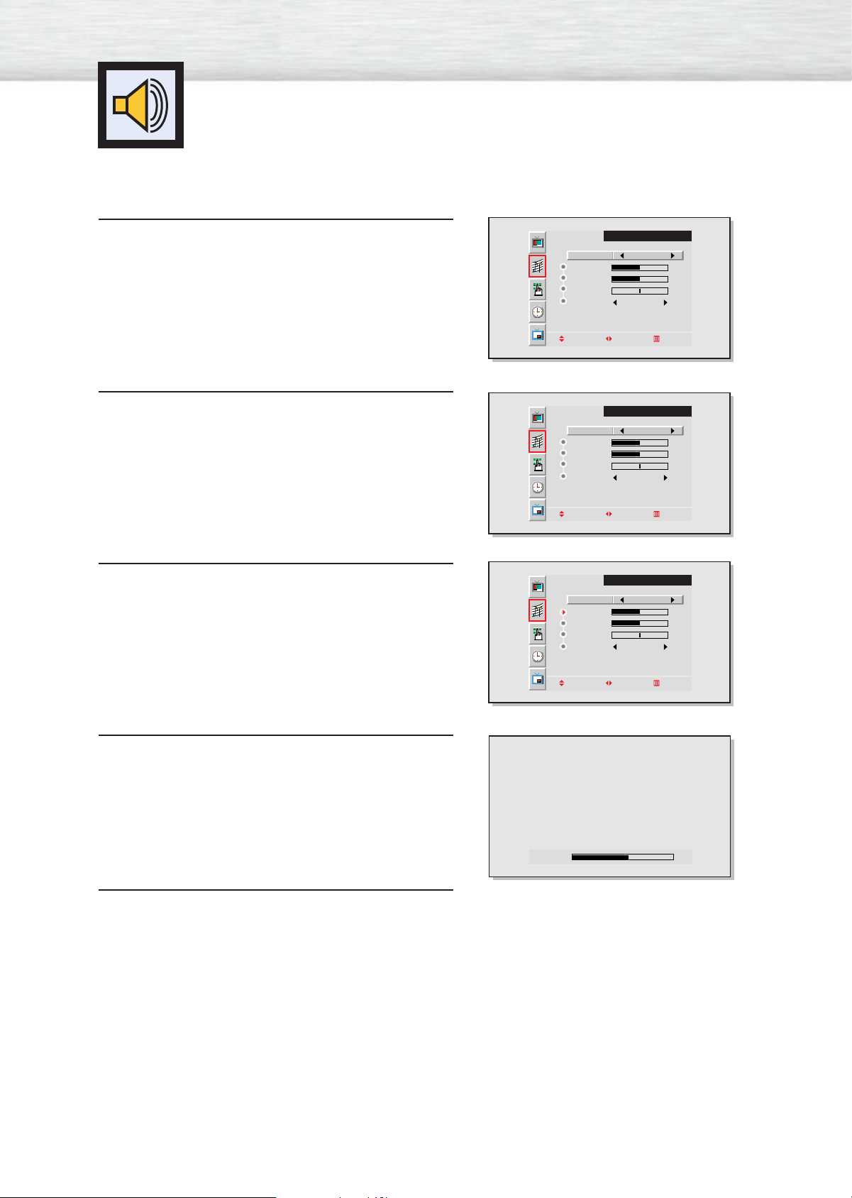
Customizing the Sound
Press the Menu button. Move the joystick up or
down to select “SOUND”, then press the joystick
1
to enter.
Move the joystick left or right to select “Custom”.
You will also see the items “Treble”, “Bass”,
2
“Balance” and “Surround”.
Move the joystick up or down to select the item you
wish to change.
3
Select
Treble
Bass
Balance
Surround Off
Move Adjust Exit
Select
Treble
Bass
Balance
Surround Off
Move Adjust Exit
Select
Treble
Bass
Balance
Surround Off
SOUND
Custom
50
50
0
SOUND
Custom
50
50
0
SOUND
Custom
50
50
0
Move the joystick left or right to change the value of
the item.
4
Press the Menu button to exit.
5
Move Adjust Exit
Treble 60
36
Page 37
Using Automatic Sound Settings
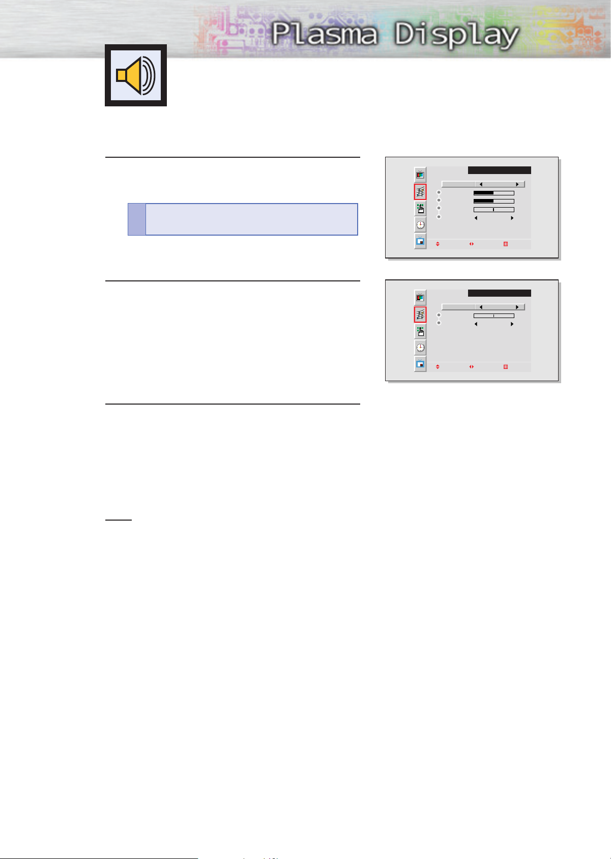
Press the Menu button. Move the joystick up or
down to select “SOUND”, then press the joystick
1
to enter.
Quick way to access the sound setting: Just press
“S.Mode” in the cover on the remote control.
!
Move the joystick left or right to select “Custom”,
“Standard”, “Music”, “Movie” or “Speech” sound
2
setting.
Press the Menu button to exit.
3
Select
Treble
Bass
Balance
Surround Off
Move Adjust Exit
Select
Balance
Surround Off
Move Adjust Exit
SOUND
Custom
50
50
0
SOUND
Standard
0
Note
• The Automatic Sound Setting function doesn’t operate in PC mode.
37
Page 38
Using the Surround
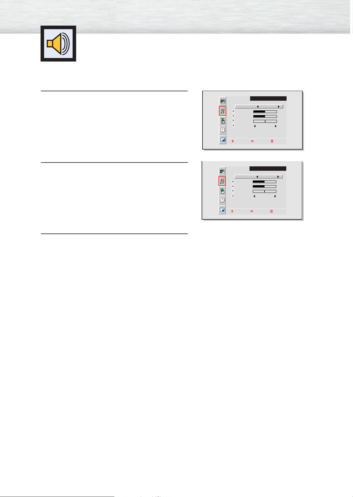
Press the Menu button. Move the joystick up or
down to select “SOUND”, then press the joystick
1
to enter.
Move the joystick up or down to select “Surround”,
then move the joystick left or right to select
2
“Concert”, “Hall” or “Stadium”.
Press the Menu button to exit.
3
Select
Treble
Bass
Balance
Surround Off
Move Adjust Exit
Select
Treble
Bass
Balance
Surround Concert
Move Adjust Exit
SOUND
Custom
50
50
0
SOUND
Custom
50
50
0
38
Page 39
PLASMA DISPLAY PANEL
Time Setting
Setting the Clock . . . . . . . . . . . . . . . . . . . . . . . . . . . . . . . . . . . . .40
Setting the Sleep Timer . . . . . . . . . . . . . . . . . . . . . . . . . . . . . . . . .41
Setting the Timers . . . . . . . . . . . . . . . . . . . . . . . . . . . . . . . . . . . .42
Page 40
Setting the Clock
This PDP has a built-in clock that will appear on screen when you press the Clock Display button on the
remote control.
Press the Menu button. Move the joystick up or
down to select “TIME”, then press the joystick to
1
enter.
Quick way to access the Clock Set : Just press
“Clock Set” in the cover on the remote control.
!
Move the joystick left or right to select hour, then
move the joystick up or down to select the correct
2
hour.
Move the joystick left or right to select minute, then
move the joystick up or down to select the correct
3
minute.
Clock
On time
Off time
On time volume
Sleep Timer
Clock Display
Move Adjust Exit
Clock
On time
Off time
On time volume
Sleep Timer
Clock Display
Adjust Move Exit
Clock
On time
Off time
On time volume
Sleep Timer
Clock Display
TIME
12 : 00 AM
12 : 00 AM Off
12 : 00 AM Off
10
Off
TIME
10 : 00 AM
12 : 00 AM Off
12 : 00 AM Off
10
Off
TIME
10 : 30 AM
12 : 00 AM Off
12 : 00 AM Off
10
Off
Move the joystick left or right to select "AM", then
move the joystick up or down to select “AM” or
4
“PM”.
• If you want to display the Clock on screen, move
the joystick down to select “Clock Display”, then
move the joystick right.
Quick way to access the clock display: Just
press “Clock Display” on the remote control.
!
Press the Menu button to exit.
5
Adjust Move Exit
Clock
On time
Off time
On time volume
Sleep Timer
Clock Display
Adjust Move Exit
TIME
10 : 30 AM
12 : 00 AM Off
12 : 00 AM Off
10
Off
40
Page 41
Setting the Sleep Timer
You can set your PDP to automatically turn off after a preset interval.
Press the Menu button. Move the joystick up or
down to select “TIME”, then press the joystick to
1
enter.
Quick way to access the sleep timer: Just press
!
“Sleep”
in the cover on the remote control.
Move the joystick up or down to select “Sleep
Timer”.
2
Move the joystick left or right to select the time interval for the PDP to stay on. The interval ranges from
3
10 to 360 minutes.
Clock
On time
Off time
On time volume
Sleep Timer
Clock Display
Move Adjust Exit
Clock
On time
Off time
On time volume
Sleep Timer
Clock Display
Move Adjust Exit
Clock
On time
Off time
On time volume
Sleep Timer
Clock Display
TIME
12 : 00 AM
12 : 00 AM Off
12 : 00 AM Off
10
Off
TIME
10 : 30 AM
12 : 00 AM Off
12 : 00 AM Off
10
Off
TIME
10 : 30 AM
12 : 00 AM Off
12 : 00 AM Off
10
10 Min.
Press the Menu button to exit.
4
Adjust Move Exit
41
Page 42
Setting the Timers
This PDP can be set to turn on or off automatically at specific times that you choose. Before using the
timers, you must set the PDP’s clock, as described previously.
Setting the On/Off Timer
Press the Menu button. Move the joystick up or
down to select “TIME”, then press the joystick to
1
enter.
Clock
On time
Off time
On time volume
Sleep Timer
Clock Display
Move Adjust Exit
TIME
12 : 00 AM
12 : 00 AM Off
12 : 00 AM Off
10
Off
Move the joystick up or down to select “On time”,
then move the joystick left or right.
2
Move the joystick left or right to select hour, then
move the joystick up or down to select the correct
3
hour.
Move the joystick left or right to select minute, then
move the joystick up or down to select the correct
4
minute.
Clock
On time
Off time
On time volume
Sleep Timer
Clock Display
Move Adjust Exit
Clock
On time
Off time
On time volume
Sleep Timer
Clock Display
Adjust Move Exit
Clock
On time
Off time
On time volume
Sleep Timer
Clock Display
TIME
10 : 30 AM
12 : 00 AM Off
12 : 00 AM Off
10
Off
TIME
10 : 30 AM
6 : 00 AM Off
12 : 00 AM Off
10
Off
TIME
10 : 30 AM
6 : 30 AM Off
12 : 00 AM Off
10
Off
42
Move the joystick left or right to select “AM”, then
move the joystick up or down to select “AM” or
5
“PM”.
Adjust Move Exit
Clock
On time
Off time
On time volume
Sleep Timer
Clock Display
Adjust Move Exit
TIME
10 : 30 AM
6 : 30 AM Off
12 : 00 AM Off
10
Off
Page 43
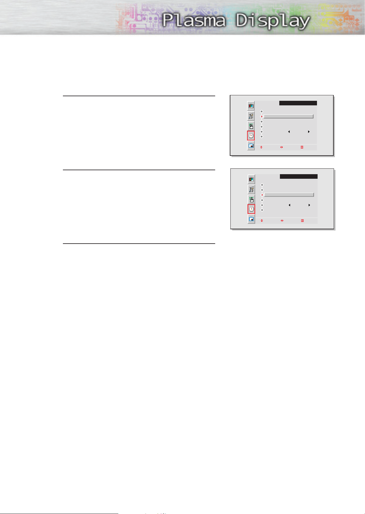
Move the joystick left or right to select “Off”, then
move the joystick up or down to select “On”.
6
Clock
On time
Off time
On time volume
Sleep Timer
Clock Display
Adjust Move Exit
TIME
10 : 30 AM
6 : 30 AM On
12 : 00 AM Off
10
Off
If you want to set the Off Time, move the joystick
down to select “Off Time”.
7
Set the “Off Time” just as you set “On Time”.
• If you want to set the volume level when the PDP
turns on, move the joystick down to select “On
time volume”. Move the joystick right to set the
volume level you want when the PDP turns on.
Press the Menu button to exit.
8
Clock
On time
Off time
On time volume
Sleep Timer
Clock Display
Move Adjust Exit
TIME
10 : 30 AM
12 : 00 AM Off
12 : 00 AM Off
10
Off
43
Page 44

Page 45

PLASMA DISPLAY PANEL
Connecting PC and Operation
Connecting to a PC ......................................................................46
Adjusting the PC Screen ................................................................50
Changing the Position of the Image ................................................51
Changing the Size of the Image ....................................................52
Enlarging the Image (Zoom) ..........................................................53
Moving the Zoom Picture ..............................................................54
Picture Quality Adjustment ............................................................55
Information ..................................................................................58
Power Saver (PC mode only)..........................................................59
Page 46
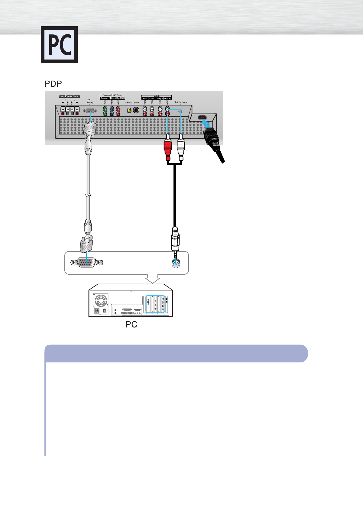
PC (15pin)
Cable
Connecting to a PC
This PDP is not compatible with Macintosh PC.
Power Plug
Audio Cable
46
Connecting a PC to the PDP
Connect a PC (15pin) cable between the Video Output jack on the PC and the PC Input jack
1
(15p D-SUB) on the PDP.
• For an explanation of Component video, see your PC owner’s instructions.
Connect a Audio cable between the Audio Output jack on the PC and the Audio Input (PC)
2
on the PDP.
To watch the PC screen:
1. Turn on PDP and press the RGB button on the remote to select the PC mode.
2. Turn on PC and check for PC system requirements.
(Refer to pages 48 and 49 for PC system requirements.)
3. Adjust the PC screen. (Refer to page 50.)
Page 47
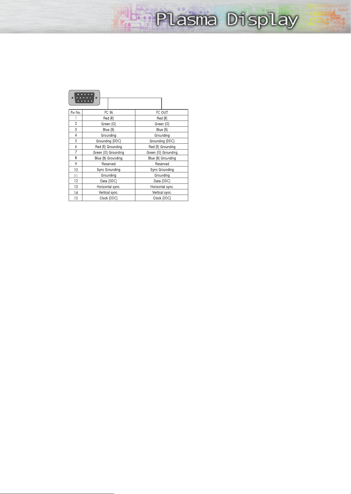
Pin Configuration
• 15Pin Signal Cable (based on protruded pin)
Setting up Your Monitor (Plug and Play)
Our adoption of the new VESAPlug and Play solution eliminates complicated and time consuming
setup. It allows you to install your monitor in a Plug and Play compatible system, without the usual
setup hassles and confusion. Your PC system can easily identify and configure itself for use with your
display. This monitor automatically tells the PC system its Extended Display Identification data (EDID)
using Display Data Channel (DDC) protocols.
47
Page 48
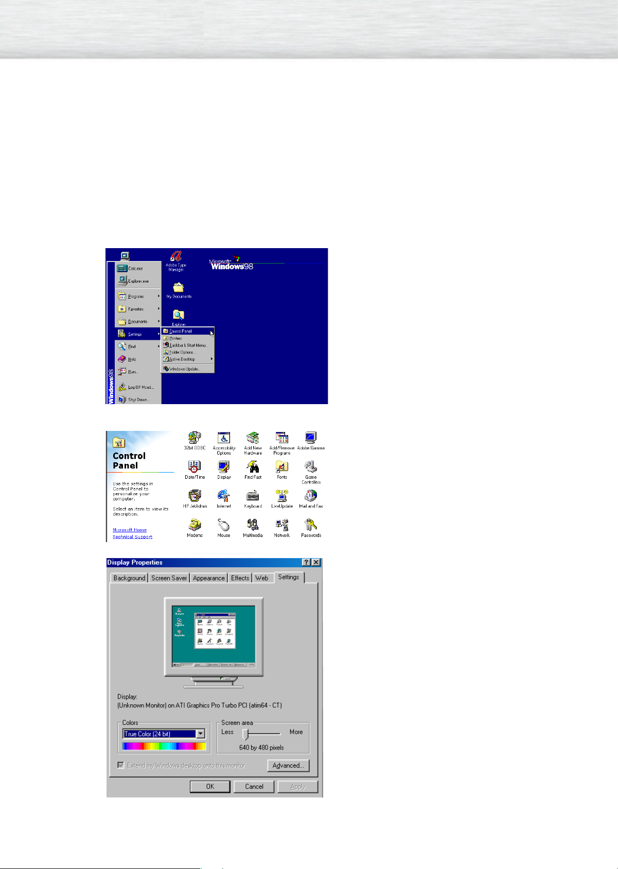
How to Set up Your PC Software (Windows only)
The Windows display-settings for a typical computer are shown below. However, the actual screens on
your PC will probably be different, depending upon your particular version of Windows and your particular video card. But even if your actual screens look different, the same, basic set-up information will
apply in almost all cases. (If not, contact your computer manufacturer or Samsung Dealer.)
On the windows screen, select in the following
sequence : Start ➝ Settings ➝ Control Panel.
When the control panel screen appears, click on
“Display” and a display dialog-box will appear.
48
Select the “Settings” tab in the display dialog-box.
The two key variables that apply the PDP-PC interface are “resolution” and “colors.” The correct settings for these two variables are:
• Size (sometimes called “resolution”):
640 x 480 pixels.
• Color: “24-bit” color (might also be expressed
as “16 million colors”)Shown at left is a typical
screen for “Display” dialog box.
If a vertical-frequency option exists on your display settings dialog box, the correct value is “60”
or “60 Hz.” Otherwise, just click “OK” and exit
the dialog box.
Continued...
Page 49
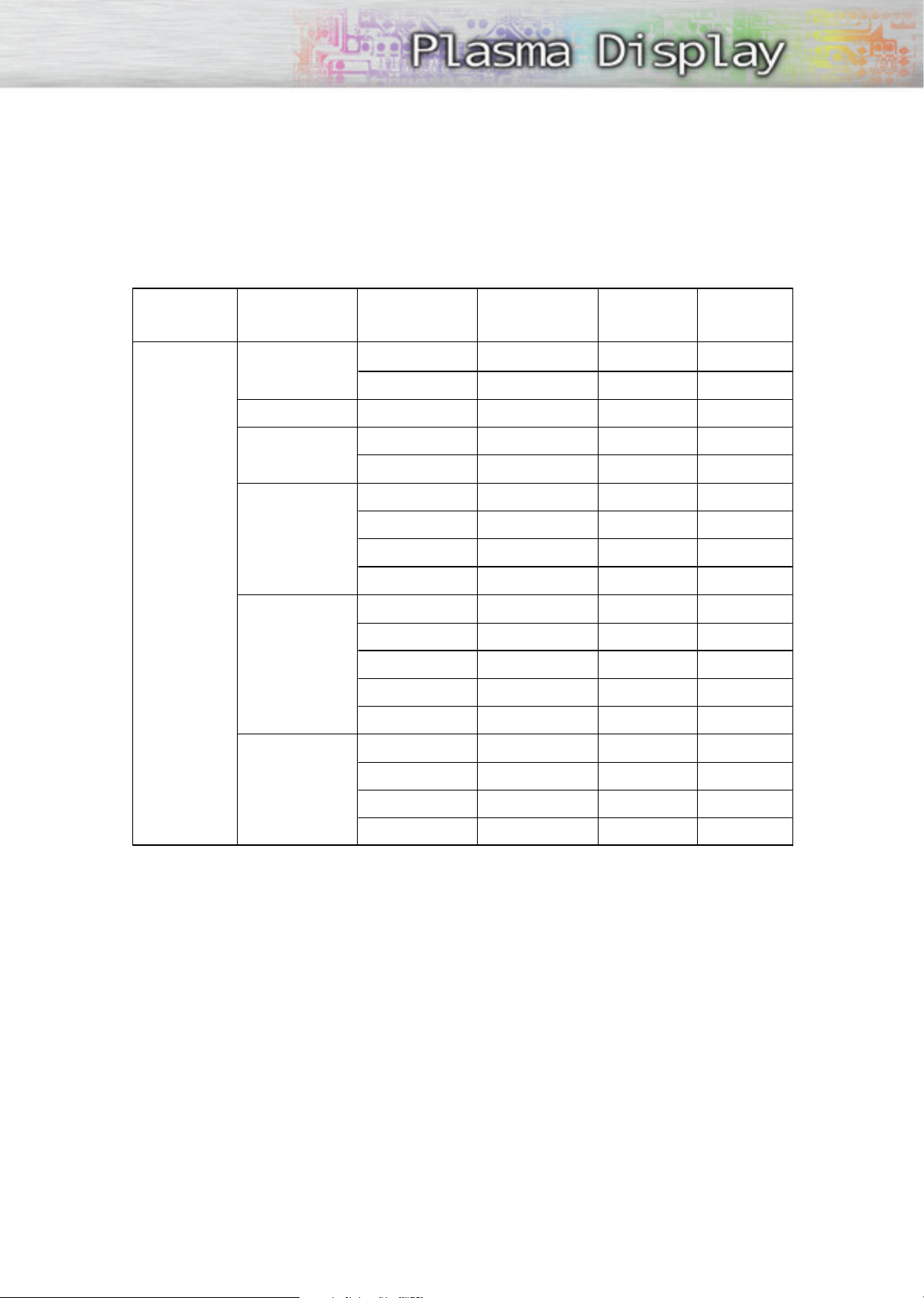
Notes:
Both screen position and size will vary, depending on the type of PC monitor and its resolution. The table
below shows all of the display modes that are supported:
Video signal Dot X Line
640 X 350
640 X 400
720 X 400
640 X 480
IBM PC / AT
Compatible
800 X 600
1024 X 768
Vertical
Frequency (Hz)
70.086
85.080
85.080
70.087
85.039
59.940
72.809
75.000
85.008
56.250
60.317
72.188
75.000
85.061
60.004
Horizontal
Frequency (KHz)
31.469
37.861
37.861
31.469
37.927
31.469
37.861
37.500
43.269
35.156
37.879
48.077
46.875
53.674
48.363
Vertical
polarity
N
N
P
P
P
N
N
N
N
N/P
P
P
P
P
N
Horizontal
polarity
P
P
N
N
N
N
N
N
N
N/P
P
P
P
P
N
70.069
75.029
84.997
56.476
60.023
68.677
N
P
P
N
P
P
• The interlace mode is not supported.
• The PDP operates abnormally if a non-standard video format is selected.
Notes:
• When this PDP is used as a PC display, 24-bit color is supported (over 16 million colors).
• Depending on the manufacturer, y our PC display screen might appear different.
(and depending on your particular version of Windows).
Check your PC instruction book for information about connecting your PC to a PDP.
• If a vertical and horizontal frequency-select mode exists, select 60Hz (vertical) and 31.5kHZ (horizontal).
•In some cases, abnormal signals (such as stripes) might appear on the screen when the PC power is turned
off (or if the PC is disconnected). If so, press the Source button to enter the VIDEO mode.
Also, make sure that the PC is connected.
• Connect only a PC monitor to the monitor output port while viewing the PC screen. (Otherwise, random
signals might appear).
49
Page 50
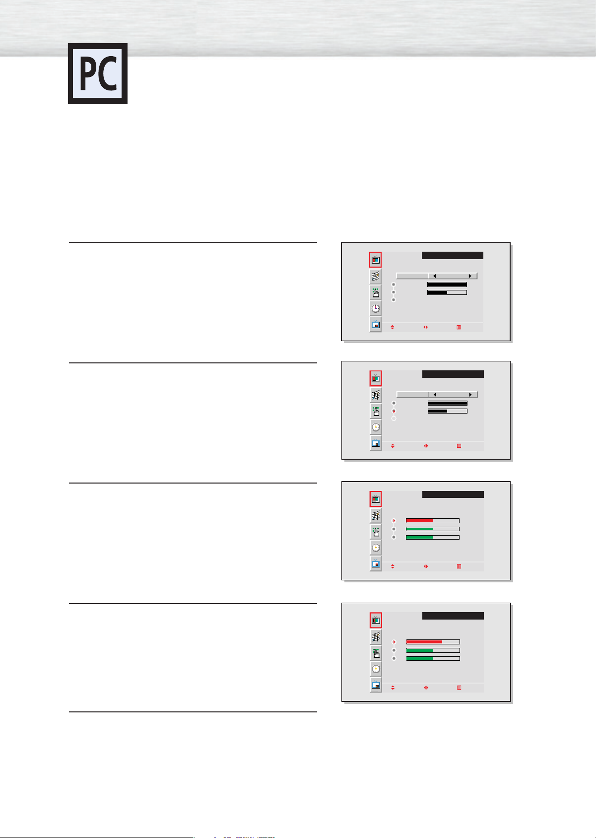
Adjusting the PC Screen
Adjusting the R.G.B
Preset:
•Press the RGB button to select the PC mode.
Press the Menu button, then press the joystick to
enter.
1
Move the joystick up or down to select “Color
Control”, then move the joystick left or right to enter.
2
Move the joystick up or down to select the item you
want to change.
3
VIDEO
Select
Contrast
Brightness
Color Control
Move Adjust Exit
Select
Contrast
Brightness
Color Control
Move Adjust Exit
R
G
B
Custom
100
50
VIDEO
Custom
100
50
VIDEO
50
50
50
50
Move the joystick right or left to change the value of
the item, using the on-screen gauge as your guide.
4
Press the Menu button to exit.
5
Move Adjust Exit
VIDEO
R
G
B
Move Adjust Exit
70
50
50
Page 51
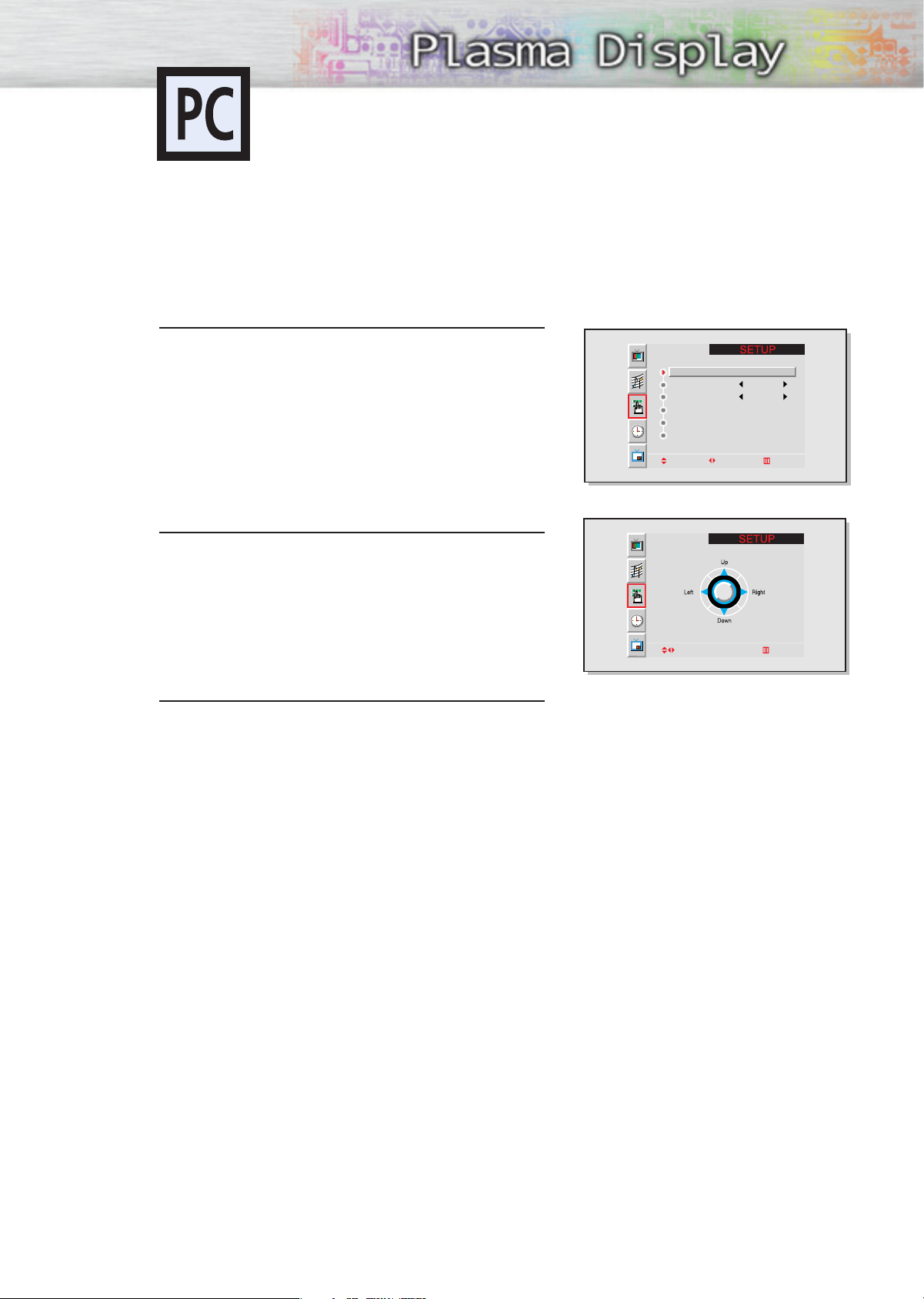
Changing the Position of the Image
After connecting the PDP to your PC, adjust the position of the screen if it is not well-aligned.
Preset:
•Press the RGB button to select the PC mode.
Press the Menu button. Move the joystick up or
down to select “SETUP”, then press the joystick
1
to enter.
Move the joystick left or right to select “Position”,
then adjust the position of screen by using the
2
joystick button.
Position
Language English
Scaling Wide
Zoom/Panning
Image Lock
Miscellaneous
Move Adjust Exit
Press the Menu button to exit.
3
Adjust Exit
51
Page 52
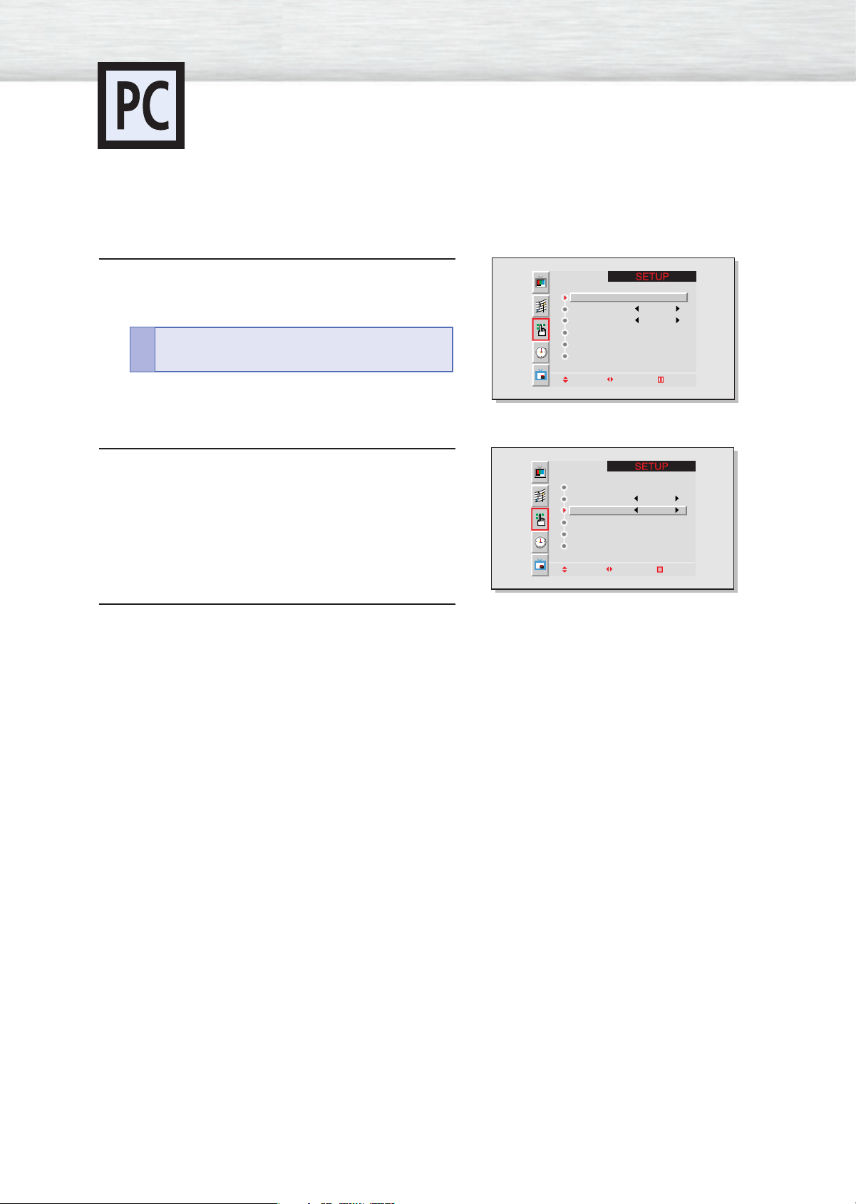
Changing the Size of the Image
Preset:
•Press the RGB button to select the PC mode.
Press the Menu button. Move the joystick up or
down to select “SETUP” , then press the joystick to
1
enter.
Quick way to access the Size: Just press
“Scaling” in the cover on the remote control.
!
Move the joystick up or down to select “Scaling”,
then move the joystick left or right to select “Wide”
2
or “4:3”.
Position
Language English
Scaling Wide
Zoom/Panning
Image Lock
Miscellaneous
Move Adjust Exit
Position
Language English
Scaling Wide
Zoom/Panning
Image Lock
Miscellaneous
Move Adjust Exit
Press the Menu button to exit.
3
52
Page 53
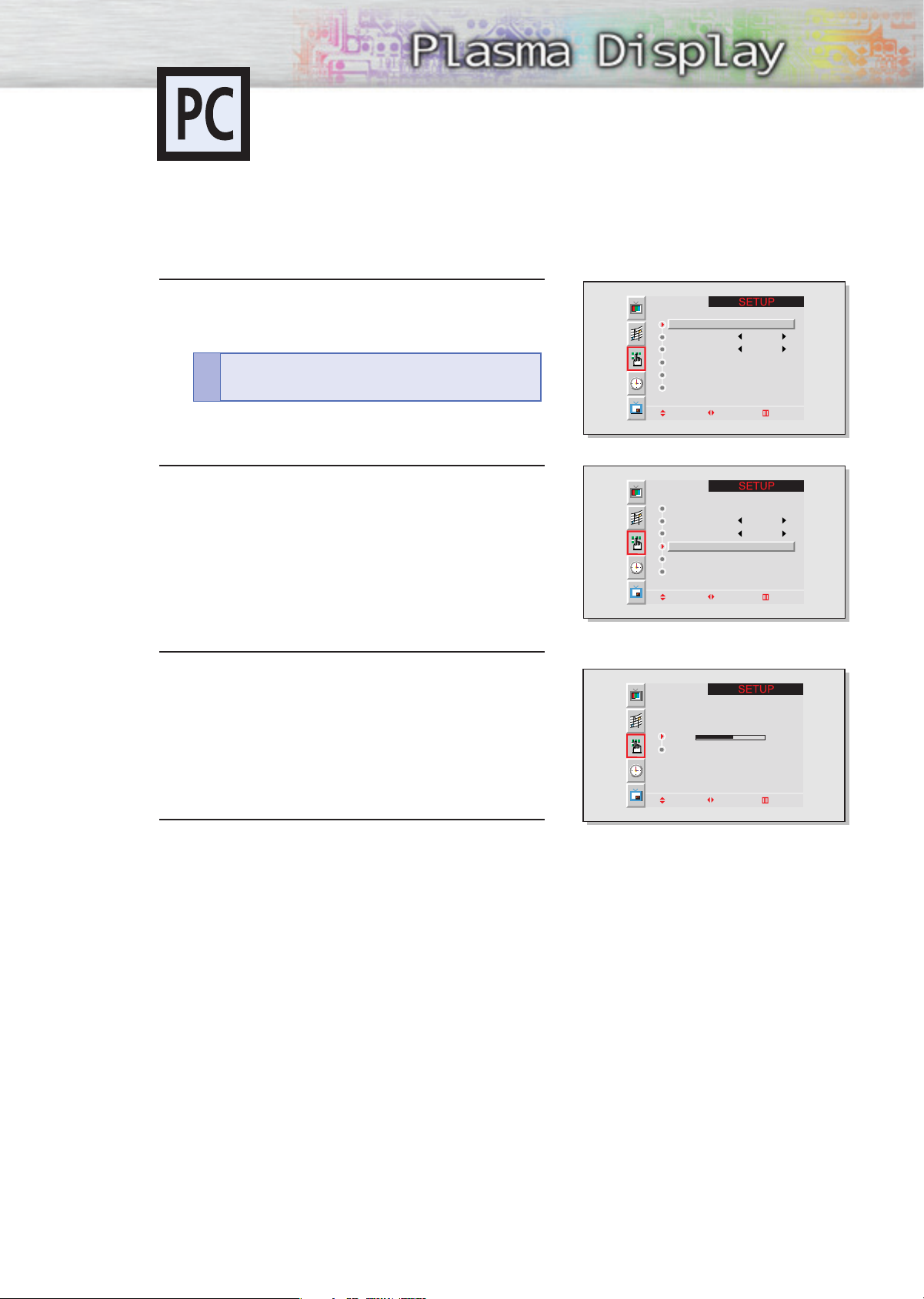
Enlarging the Image (Zoom)
Preset:
•Press the RGB button to select the PC mode.
Press the Menu button. Move the joystick up or
down to select “SETUP”, then press the joystick to
1
enter.
Quick way to access the Zoom: Just press
“Zoom/Pan” in the cover on the remote control.
!
Move the joystick up or down to select “Zoom/Panning”, then move the joystick left or right to enter.
2
Position
Language English
Scaling Wide
Zoom/Panning
Image Lock
Miscellaneous
Move Adjust Exit
Position
Language English
Scaling Wide
Zoom/Panning
Image Lock
Miscellaneous
Move Adjust Exit
Move the joystick left or right to enlarge the image.
• The picture can be expanded 0 to 10 in Zoom
3
mode.
Press the Menu button to exit.
4
Zoom 5
Panning
Move Adjust Exit
53
Page 54
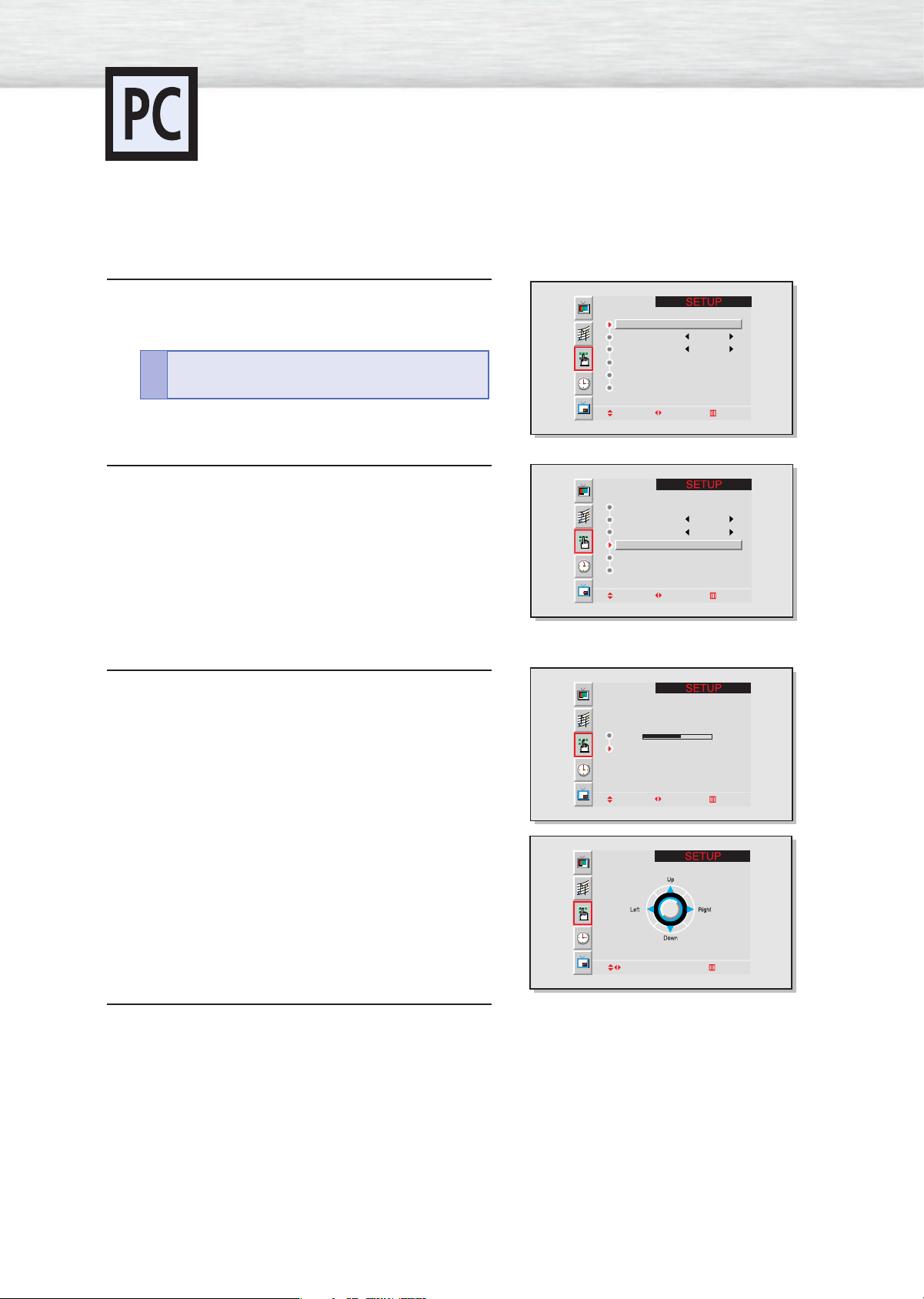
Moving the Zoom Picture
Preset:
•Press the RGB button to select the PC mode.
Press the Menu button. Move the joystick up or
down to select “SETUP”, then press the joystick to
1
enter.
Quick way to access the Panning : Just press
“Zoom/Pan” in the cover on the remote control.
!
Move the joystick up or down to select “Zoom/Panning”, then move the joystick left or right to enter.
2
Position
Language English
Scaling Wide
Zoom/Panning
Image Lock
Miscellaneous
Move Adjust Exit
Position
Language English
Scaling Wide
Zoom/Panning
Image Lock
Miscellaneous
Move Adjust Exit
Move the joystick up or down to select “Panning”,
then move the joystick left or right to enter.
3
Adjust the position of screen by using the joystick
button.
• The Panning feature operates only when the picture is in Zoom mode.
Press the Menu button to exit.
4
Zoom 5
Panning
Move Adjust Exit
Adjust Exit
54
Page 55
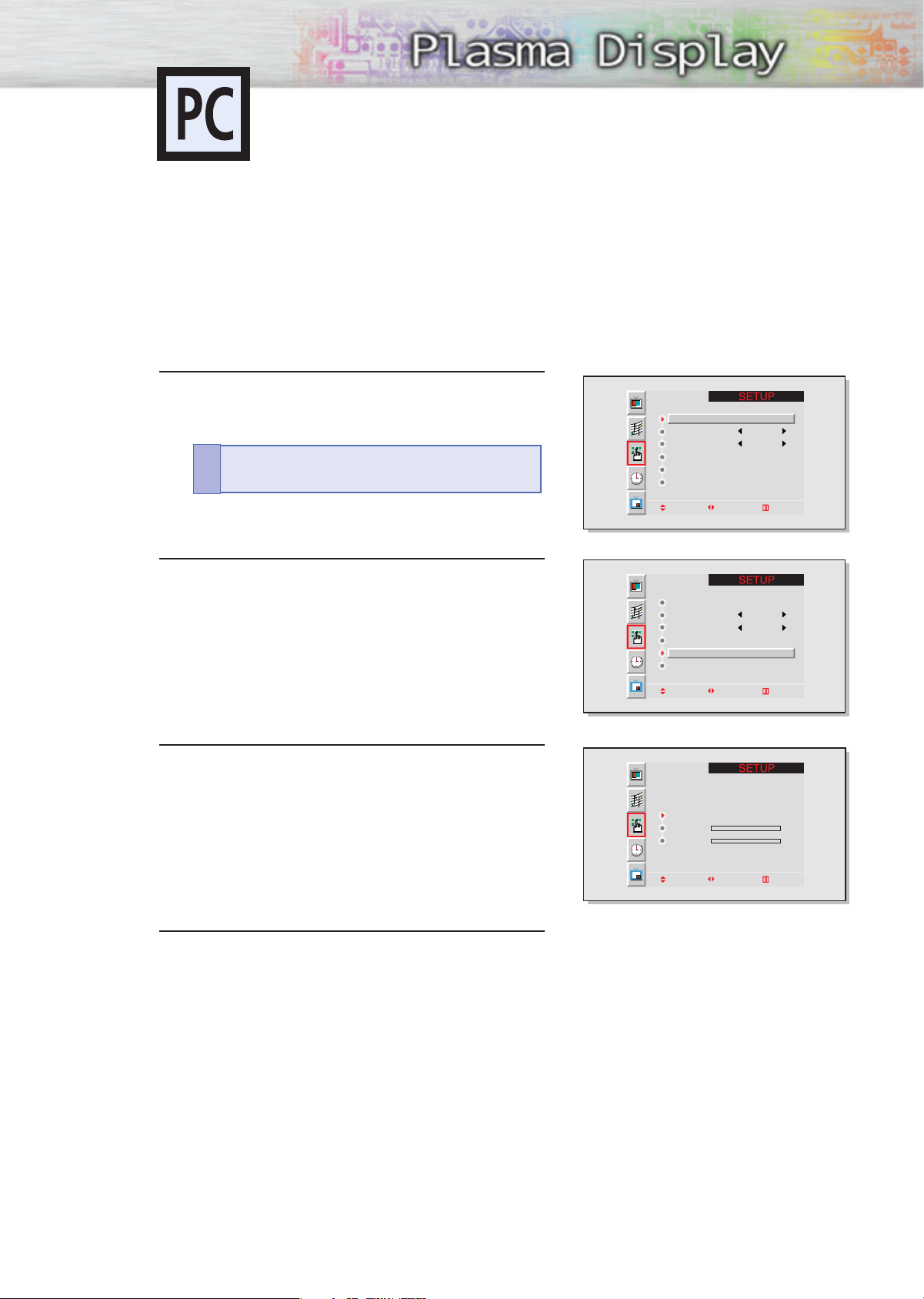
Picture Quality Adjustment
Picture Automatic Adjustment On/Off
Preset:
•Press the RGB button to select the PC mode.
Press the Menu button. Move the joystick up or
down to select “SETUP”, then press the joystick to
1
enter.
Quick way to access the Auto Adjust: Just press
“Auto Adjust.” in the cover on the remote control.
!
Position
Language English
Scaling Wide
Zoom/Panning
Image Lock
Miscellaneous
Move Adjust Exit
Move the joystick up or down to select “Image
Lock”, then move the joystick left or right to enter.
2
Move the joystick up or down to select “Auto
Adjust”, then move the joystick left or right.
3
The message “Auto in progress” appears on the
screen and the picture adjustments are automatically
activated.
Press the Menu button to exit.
4
Position
Language English
Scaling Wide
Zoom/Panning
Image Lock
Miscellaneous
Move Adjust Exit
Auto Adjustment
Frequency 0
Phase 0
Move Adjust Exit
55
Page 56
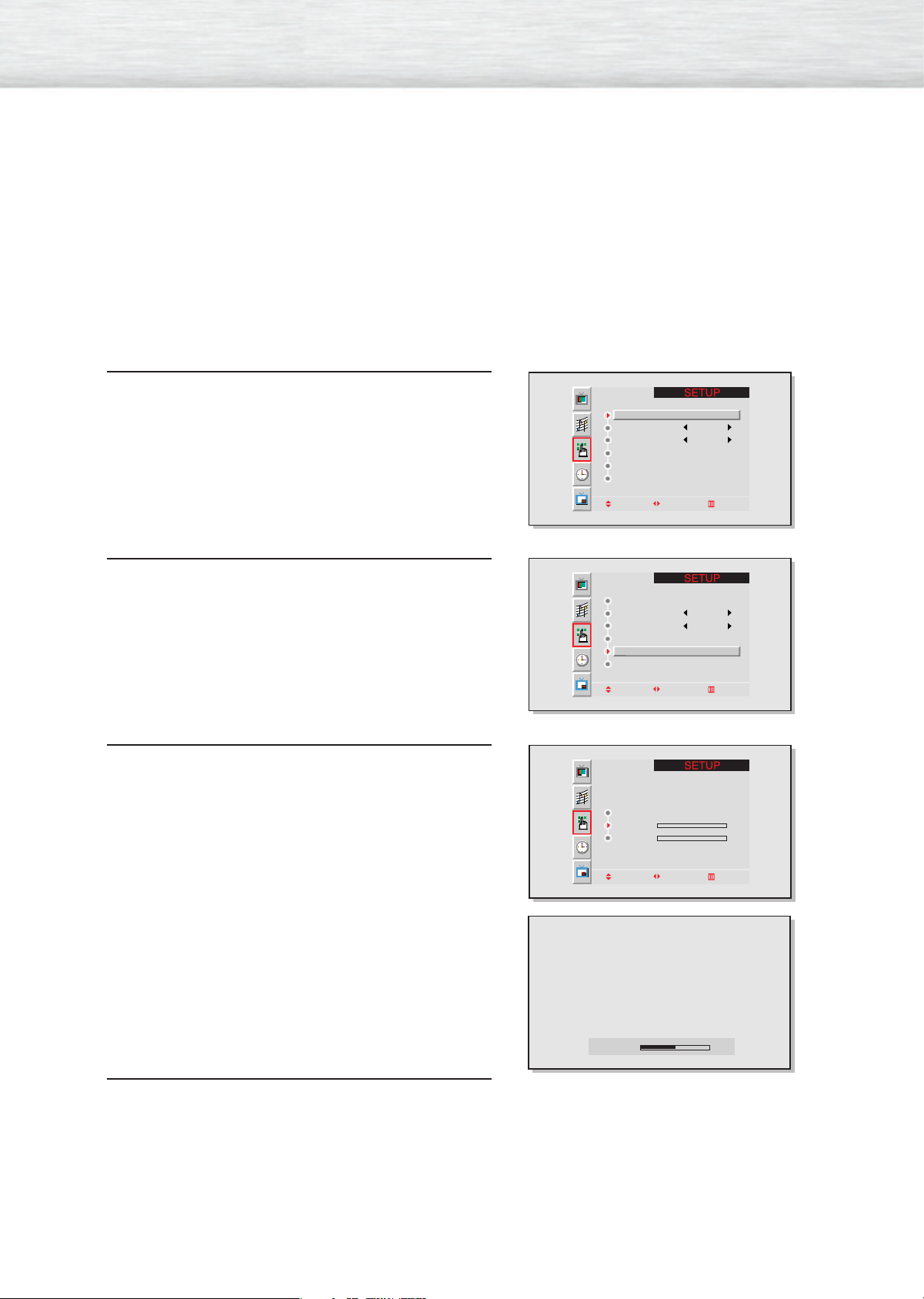
Frequency Adjustment
Preset:
•Press the RGB button to select the PC mode.
Press the Menu button. Move the joystick up or
down to select “SETUP”, then press the joystick to
1
enter.
Move the joystick up or down to select “Image
Lock”, then move the joystick left or right to enter.
2
Position
Language English
Scaling Wide
Zoom/Panning
Image Lock
Miscellaneous
Move Adjust Exit
Position
Language English
Scaling Wide
Zoom/Panning
Image Lock
Miscellaneous
Move Adjust Exit
Remove picture noise (vertical stripes) on the screen
by moving the joystick left or right.
3
(If frequency is not set properly, vertical stripes
will appear on the screen.)
Press the Menu button to exit.
4
Auto Adjustment
Frequency 0
Phase 0
Move Adjust Exit
Frequency 50
56
Page 57
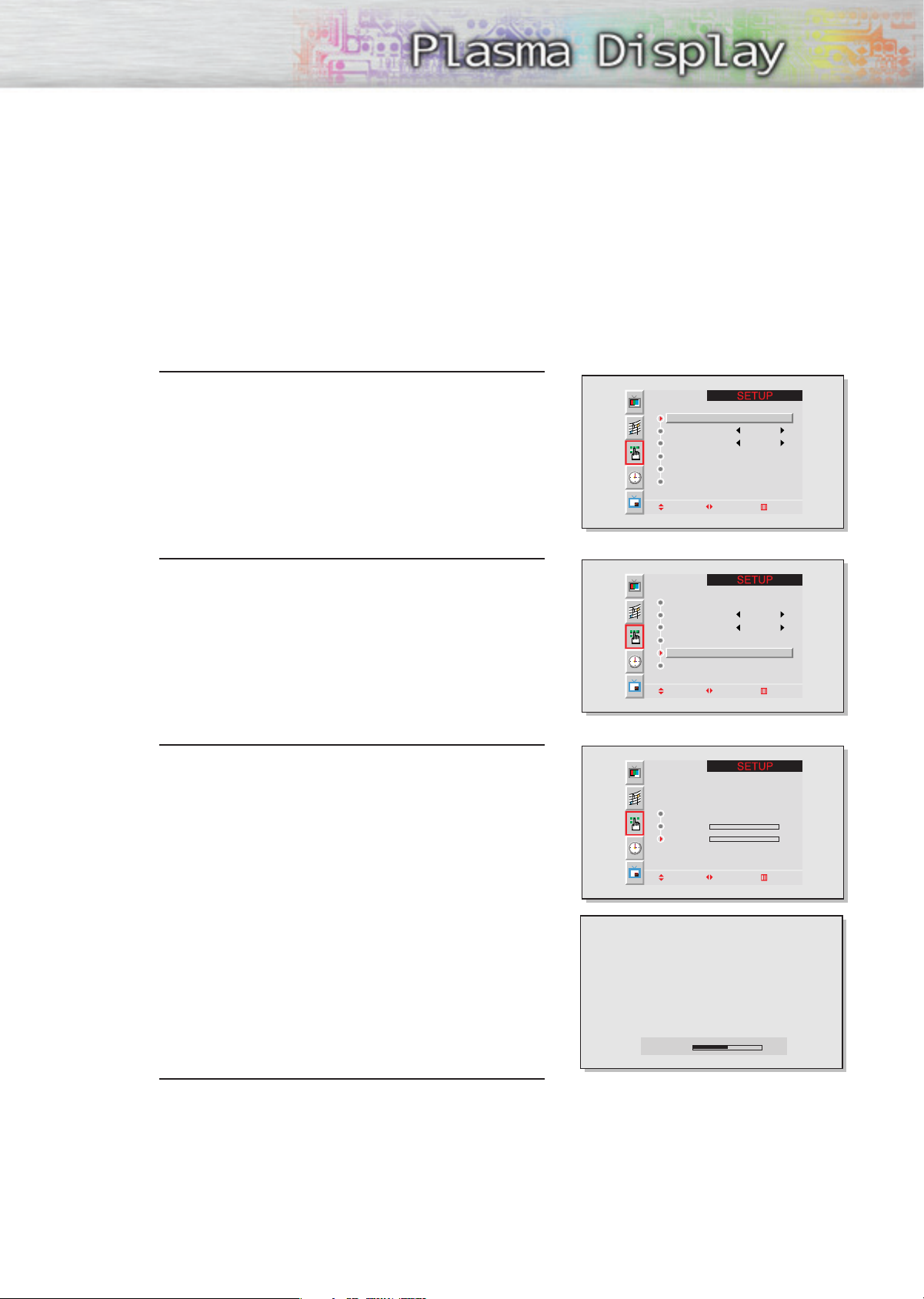
Fine Tuning (Phase)
Preset:
•Press the RGB button to select the PC mode.
Press the Menu button. Move the joystick up or
down to select “SETUP”, then press the joystick to
1
enter.
Move the joystick up or down to select “Image
Lock”, then move the joystick left or right to enter.
2
Position
Language English
Scaling Wide
Zoom/Panning
Image Lock
Miscellaneous
Move Adjust Exit
Position
Language English
Scaling Wide
Zoom/Panning
Image Lock
Miscellaneous
Move Adjust Exit
Move the joystick up or down to select “Phase”.
3
Remove picture noise (vertical stripes) on the screen
by moving the joystick left or right.
(If phase is not set properly, the picture may be
blurry.)
Press the Menu button to exit.
4
Auto Adjustment
Frequency 0
Phase 0
Move Adjust Exit
Phase 50
57
Page 58
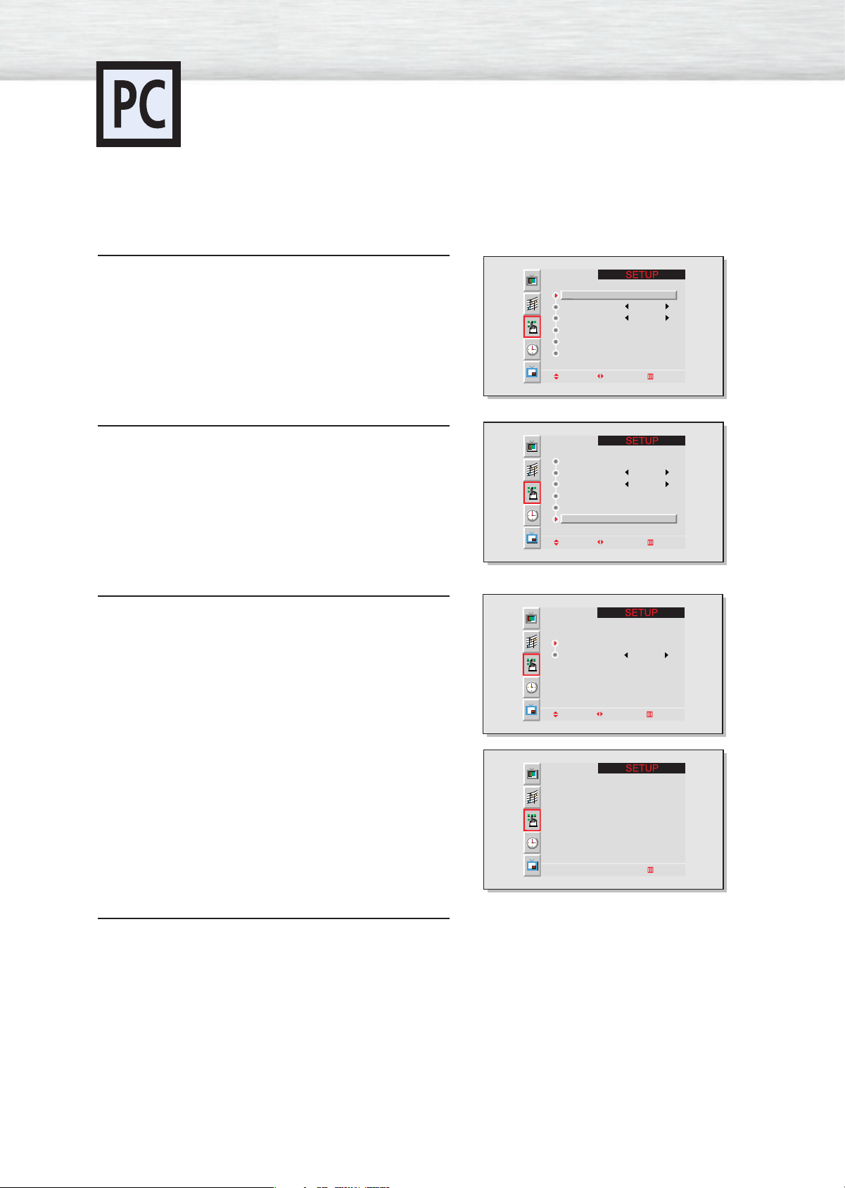
Information
Preset:
•Press the RGB button to select the PC mode.
Press the Menu button. Move the joystick up or
down to select “SETUP”, then press the joystick to
1
enter.
Move the joystick up or down to select “Miscellaneous”, then move the joystick left or right to
2
enter.
Position
Language English
Scaling Wide
Zoom/Panning
Image Lock
Miscellaneous
Move Adjust Exit
Position
Language English
Scaling Wide
Zoom/Panning
Image Lock
Miscellaneous
Move Adjust Exit
Move the joystick up or down to select “Information”, then move the joystick left or right to enter.
3
Press the Menu button to exit.
4
Information
Key Lock Off
Move Adjust Exit
Horizontal Vertical
Resolution
Frequency
640 480
31.5KHz 60Hz
Exit
58
Page 59
Power Saver (PC mode only)
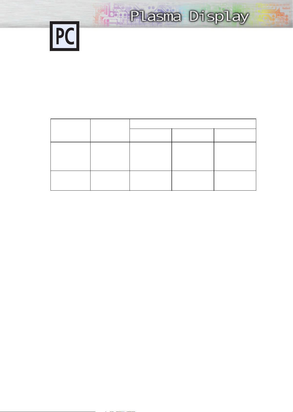
This monitor has a built-in power management system called Power Saver. This power management
system saves energy by switching your monitor into a low-power mode when it has not been used for a
certain amount of time. This power management system operates with a VESA DPMS compliant video
card installed in your computer. You use a software utility installed on your computer to set up this feature. See the table below for details.
Table 1. Power-saving modes
State
Horizontal Sync
Vertical Sync
Video
Power
Indicator
Notes:
• This monitor automatically returns to normal operation when horizontal and vertical sync return.
• This occurs when moving the computer’s mouse or pressing a key on the keyboard.
• For energy conservation, turn your monitor OFF when it is not needed, or when leaving it unattended for long periods.
Operation
Active
Active
Active
Green
Standby Mode
Inactive
Active
Blanked
Red Blinking
(1 sec Interval)
Normal
Power-saving Function Mode
Suspend Mode
Position A1
Active
Inactive
Blanked
Red Blinking
(1 sec Interval)
Power-off Mode
Position A2
Inactive
Inactive
Blanked
Red Blinking
(1 sec Interval)
59
Page 60

Page 61
PLASMA DISPLAY PANEL
Function Description
Selecting a Menu Language . . . . . . . . . . . . . . . . . . . . . . . . . . . . .62
Setting the Multi Control . . . . . . . . . . . . . . . . . . . . . . . . . . . . . . . .63
Using the Key Lock . . . . . . . . . . . . . . . . . . . . . . . . . . . . . . . . . . .64
Setting up Your Remote Control . . . . . . . . . . . . . . . . . . . . . . . . . . .65
Page 62
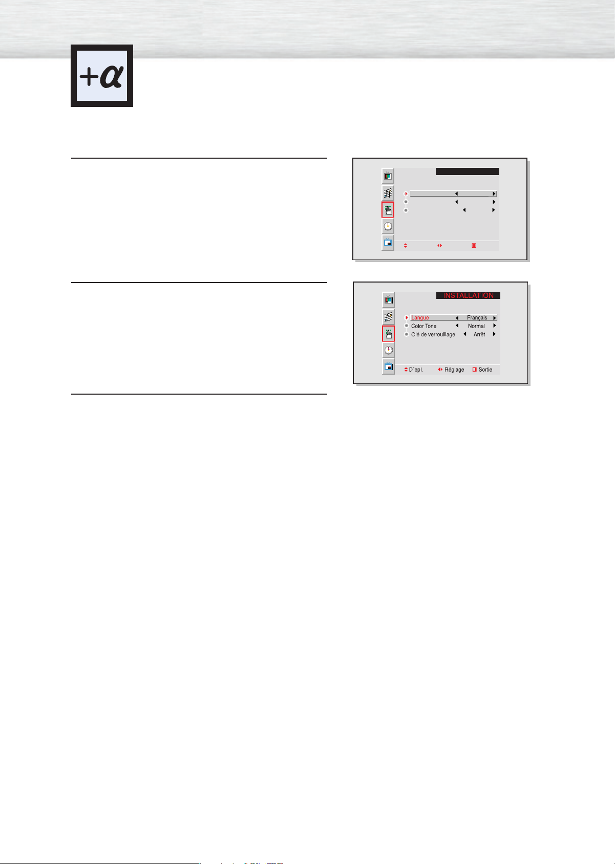
Selecting a Menu Language
Press the Menu button. Move the joystick up or
down to select “SETUP”, then press the joystick
1
to enter.
Move the joystick left or right to select the appropriate language: English, Spanish, or French.
2
Press the Menu button to exit.
3
SETUP
Language English
Color Tone Normal
Key Lock Off
Move Adjust Exit
62
Page 63
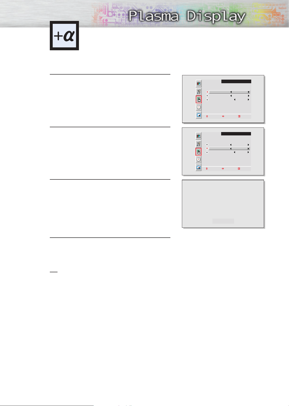
Setting the Color Tone
Press the Menu button. Move the joystick up or
down to select “SETUP”, then press the joystick
1
to enter.
Move the joystick up or down to select “Color Tone”.
2
Move the joystick left or right to select the Color
Tone : Normal, Warm1, Warm2, Cool1, Cool2.
3
SETUP
Language English
Color Tone Normal
Key Lock Off
Move Adjust Exit
SETUP
Language English
Color Tone Normal
Key Lock Off
Move Adjust Exit
Press the Menu button to exit.
4
Note
• In the PC mode, you can’t adjust the Color Tone.
Warm1
63
Page 64
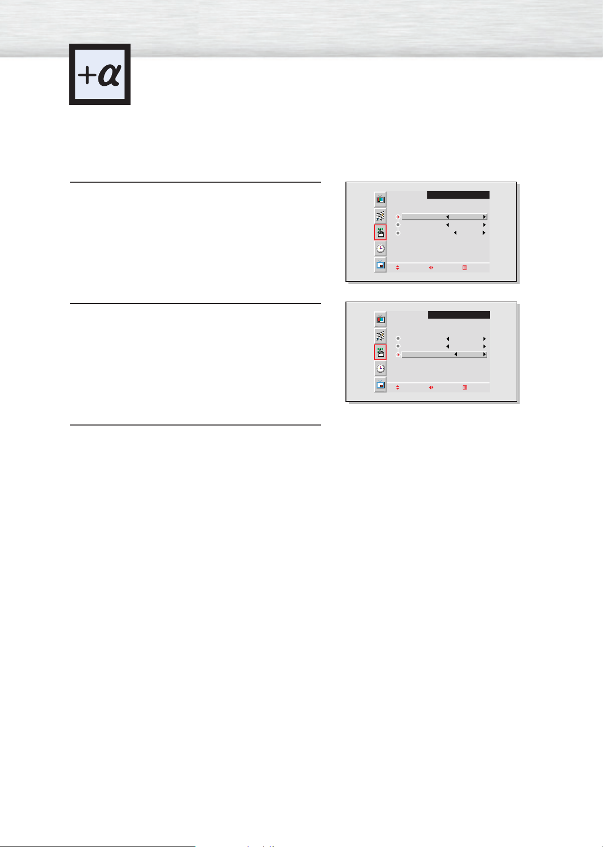
Using the Key Lock
When Key Lock is set to ON, the buttons (SOURCE, MENU, VOLUME, SELECT , MUTE, POWER) on
the front of the PDP will not operate. However, these buttons will operate when setting Key Lock OFF .
Press the Menu button. Move the joystick up or
down to select “SETUP”, then press the joystick
1
to enter.
Move the joystick up or down to select “Key Lock”,
then move the joystick left or right to select
2
“On” or “Off”.
Press the Menu button to exit.
3
SETUP
Language English
Color Tone Normal
Key Lock Off
Move Adjust Exit
SETUP
Language English
Color Tone Normal
Key Lock On
Move Adjust Exit
64
Page 65
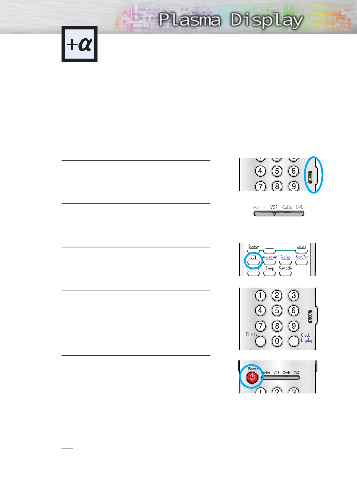
Setting up Your Remote Control
This PDP's remote control can operate almost any VCR, cable box, or DVD. After it has been set up
properly, your remote control can operate in four different modes :Monitor, VCR, Cable, or DVD.
Pressing the corresponding button on the remote control allows you to switch between these modes,
and control whichever piece of equipment you choose.
Note:The remote control may not be compatible with all DVD Players, VCRs, and Cable boxes.
Setting Up the Remote to Operate Your VCR, Cable box, or DVD player
Turn off your VCR. (or Cable box, DVD player.)
1
Press the MODE button and make sure that the VCR
(or Cable box, DVD) LED is illuminated.
2
Press the Set button on your PDP's remote control.
3
Using the number buttons on your remote control,
enter three digits of the VCR (or Cable box, DVD)
4
code listed on page 64 of this manual for your
brand of VCR (or Cable box, DVD player). Make
sure you enter three digits of the code, even if the
first digit is a "0".
(If more than one code is listed, try the first one.)
Press the Power button on the remote control.
Your VCR (or Cable box, DVD player) should turn
5
on if your remote is set up correctly. If your VCR (or
Cable box, DVD player) does not turn on after set
up, repeat steps 2, 3, and 4, but try one of the other
codes listed for your brand of VCR (or Cable box,
DVD player).
If no other codes are listed, try each code, 000
through 089 (or Cable box: 0000 through 077,
DVD player: 000 through 008).
S.Sel
Notes
• When your remote control is in “VCR” mode, the VCR control buttons (Stop, REW, Play/Pause, FF)
still operate your VCR.
• When your remote control is in “Cable box” or “DVD” mode, the VCR control buttons (Stop, REW,
Play/Pause, FF) still operate your VCR.
65
Page 66
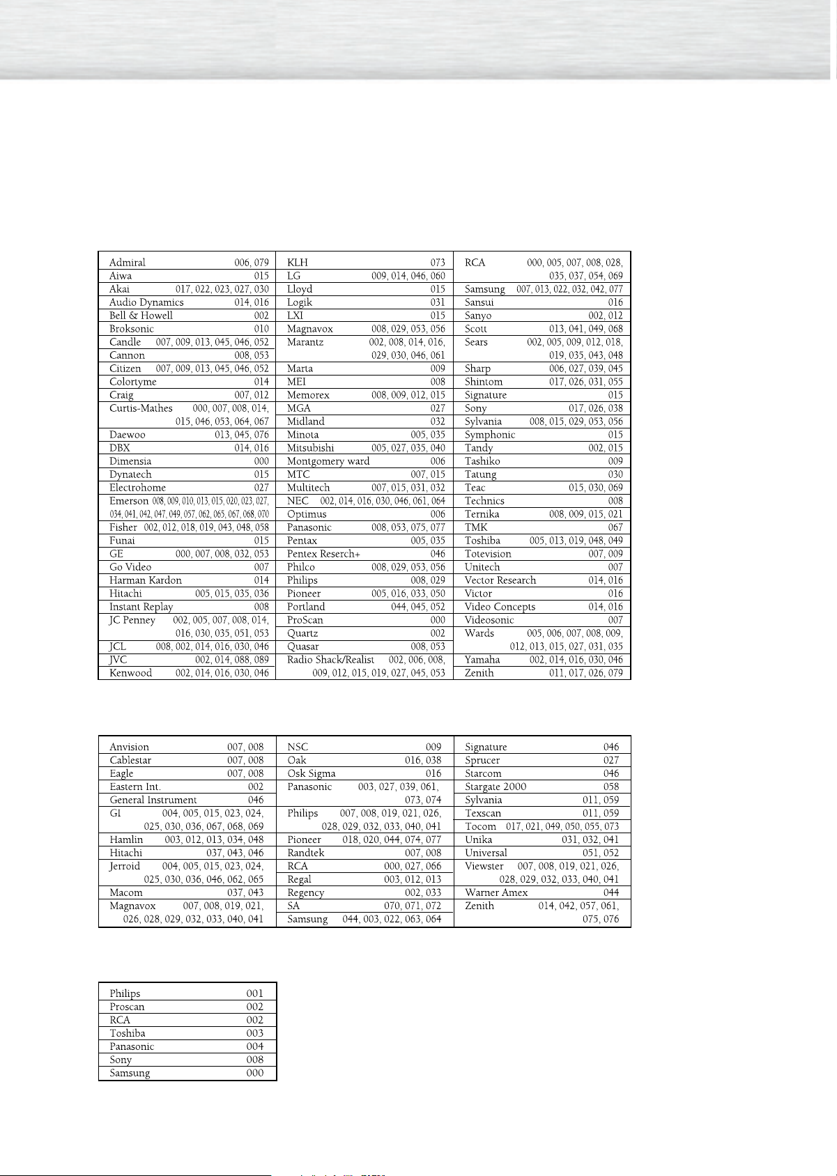
Remote Control Codes
VCR Codes
Cable Box Codes
DVD Codes
66
Page 67
PLASMA DISPLAY PANEL
Appendix
Troubleshooting............................................................................68
Care and Maintenance ................................................................69
Specifications ..............................................................................70
Page 68
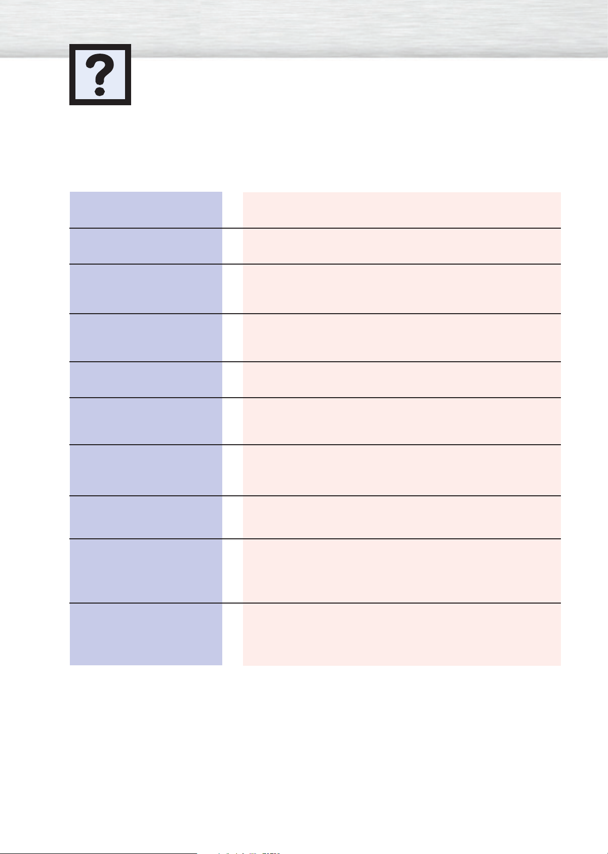
Troubleshooting
Before you call a service technician, please scan this list of problems and possible solutions. It may save you
time and money.
Problem
Poor picture.
The power indicator is
blinking amber.
Your Remote control does not
operate the monitor.
The monitor won’t turn on.
There is no screen image.
The image is too light or
too dark.
Possible Solution
Check all wire connections.
The monitor is using its power management system.
Check the power management utility on your computer.
Press the “Mode” button to put your remote control in the
“Monitor” mode.
Make sure the wall outlet is working.
Check to see that both the monitor and the source are plugged
in and turned on.
Adjust the Brightness or Contrast settings.
The image is too large or
too small.
The message "Check Temp"
blinks on the screen and then
the picture switches OFF.
The message "Check Fan”
blinks on the screen and then
the picture switches OFF.
Adjust the Size settings.
The PDP is overheated. Power off the PDP and let it cool for a
while.
The cooling fan of the PDP may have a problem. Contact an
authorized service center.
68
Page 69
Care and Maintenance
With proper care, your PDP will give you many years of service. Please follow these guidelines to get
the maximum performance from your PDP.
Identifying Problems
• Do not put the PDP near extremely hot, cold, humid or dusty places.
• Do not put the PDP near appliances that create magnetic fields.
• Keep the ventilation openings clear.
• Do not place the PDP on a rough and slanted surface, such as cloth or paper.
Liquids
• Do not place liquids near or on the PDP.
Cabinet
• Never open the cabinet or touch the parts inside.
•Wipe your PDP with a clean, dry cloth. Never use water, cleaning fluids, wax, or chemicals.
• Do not put heavy objects on top of the cabinet.
Temperature
• If your PDP is suddenly moved from a cold to a warm place, unplug the power cord for at least two
hours so that moisture that may have formed inside the unit can dry completely.
69
Page 70
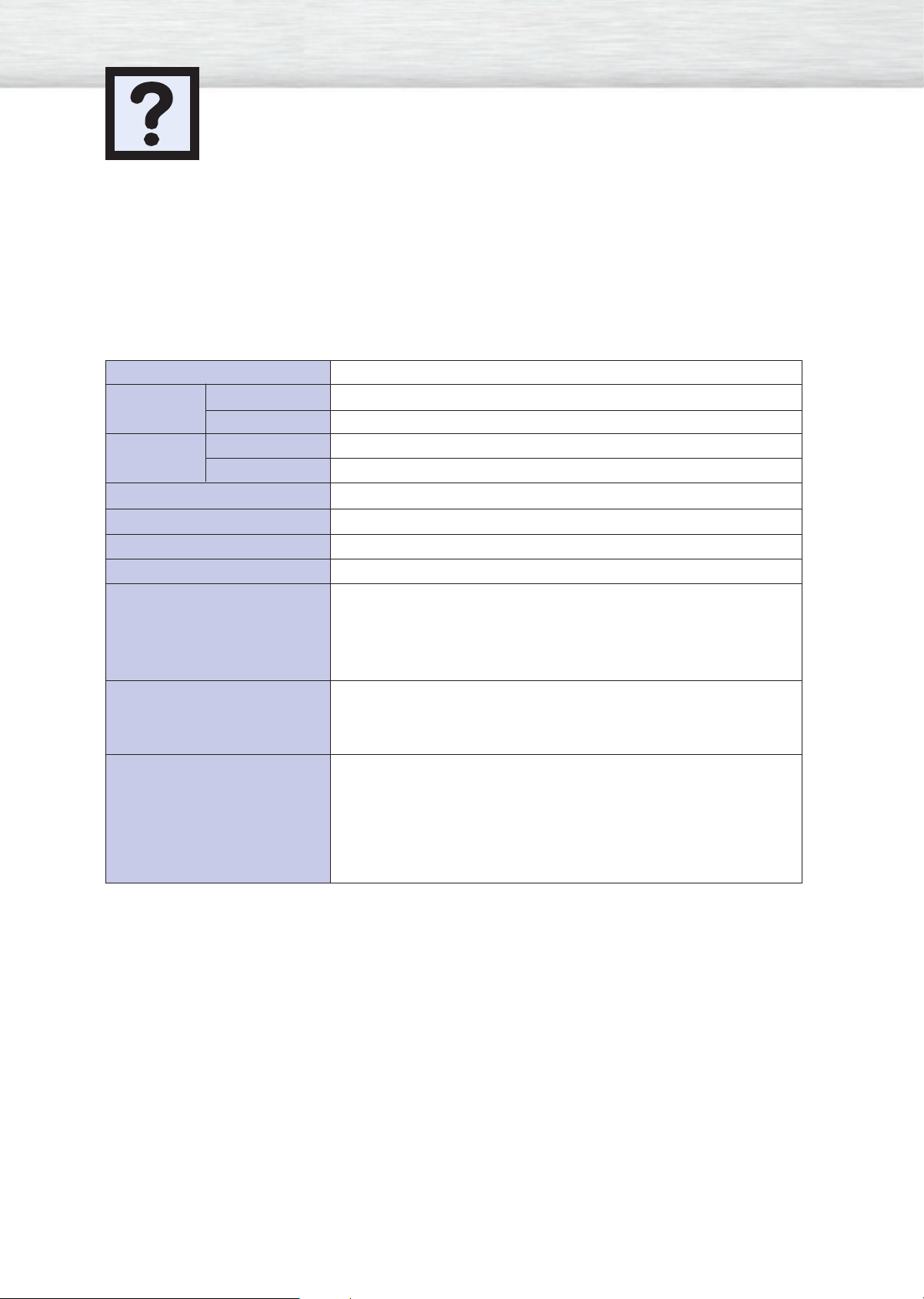
Specifications
Exterior design and product specifications are subject to change without prior notice to improve the
performance of this product.
This PDP applies to Class B digital device.
(Note: Class B system is for home use.)
This PDP has been registered for residential use in terms of EMI. So it can be used in all areas as well
as residential areas.
Model
Dimensions Display
Remote Control
Weight Display
Remote Control
Voltage
Power Consumption
Number of Pixels
Screen Size
AUDIO input
AUDIO output
VIDEO input
SPL4225
1038.8 (W) X 89 (D) X 635 (H) mm ; 40.90 (W) X 3.50 (D) X 25.00(H) inches
54 (W) X 31.5 (D) X 220 (H) mm ; 2.13 (W) X 1.24 (D) X 8.66 (H) inches
32kg ; 70.55lbs
150g (including batteries) ; 0.33lbs
100-240V~, 50/60Hz, 4A
310 Watts
852(H) x 480(V)
106 Cm/42 inches
VIDEO / S-VIDEO
COMPONENT 1
COMPONENT 2
PC (RGB)
7W + 7W (8 Ω)
VIDEO
S-VIDEO
COMPONENT 1 - 480i / 480p
COMPONENT 2 - 480p/720p/1080i
RGB : D-SUB 15P
70
Page 71
Memo
71
Page 72
Samsung Electronics America inc.
105 Challenger Road, Ridgefield Park, N.J. 07660-0511, U.S.A
SERVICE DIVISION
TEL: 1-800-SAMSUNG (1-800-726-7864)
www.samsungsupport.com
BN68-00262A-01(ENG)
 Loading...