

Page 1

USER MANUAL
Wearable Health Monitoring System
(MODEL: S-PATCH3-Cardio)
Samsung SDS Co., Ltd.
Caution: Federal law restricts this device to sale by or on the order of a physician.
Document No: SDS-UM-01 (Rev. 0)
125, Olympic-ro 35-gil, Songpa-gu, Seoul, Republic of Korea
[1]
Page 2

Revision History
Revision
Number
Issue Date
Contents of revision
Rev.0.0
2017.07.12
Established by Manufacturer’s User Manual Policy
[2]
Page 3

Contents
1. Product Introduction .................................................................................................................................... 5
1.1 Introducing S-PATCH3-CARDIO ......................................................................................................... 5
1.2 Indication for Use ...................................................................................................................................... 5
2. Cautions ............................................................................................................................................................. 5
2.1 General ......................................................................................................................................................... 5
2.2 Safety ............................................................................................................................................................ 5
2.3 Contra-Indication ....................................................................................................................................... 6
2.4 Usage and Storage Conditions ................................................................................................................ 7
2.4.1 Conditions for Usage ........................................................................................................................ 7
2.4.2 Conditions for Storage ...................................................................................................................... 7
2.4.3 Cleaning Condition ........................................................................................................................... 7
3. Components and Installation of S-PATCH3-CARDIO ............................................................................ 8
3.1 Main Device Components ........................................................................................................................ 8
3.2 Accessory Components ............................................................................................................................ 9
3.3 How to Install S-PATCH3-CARDIO ................................................................................................. 10
3.3.1 Installing S-PATCH ....................................................................................................................... 10
3.4 Precautions ............................................................................................................................................... 11
4. Using and Operating S-PATCH3-CARDIO ............................................................................................. 12
4.1 How to Use S-PATCH3-CARDIO ..................................................................................................... 12
4.2 Specifications ........................................................................................................................................... 17
4.2.1 S-PATCH3-CARDIO Specifications ......................................................................................... 17
4.3 Error Message .......................................................................................................................................... 18
4.4 Maintenance ............................................................................................................................................. 18
4.5 Specification of External Device connection .................................................................................... 18
5. Heart Rate Algorithm .................................................................................................................................... 19
5.1 HR calculation per beat .................................................................................................................... 19
5.2 Average HR calculation of a section .......................................................................................... 19
[3]
Page 4

6. Labels and Packaging .................................................................................................................................... 20
6.1 Labels ......................................................................................................................................................... 20
6.1.1 Label for Packaging ....................................................................................................................... 20
6.1.2 Label for module ............................................................................................................................. 20
6.2 Packaging .................................................................................................................................................. 21
6.2.1 Package List ..................................................................................................................................... 21
6.2.2 Package Units .................................................................................................................................. 21
6. Information on EMC ....................................................................................................................................... 22
6.1 Guidance and Manufacturer’s Declaration – Electromagnetic Emissions ................................. 22
6.2 Guidance and Manufacturer’s Declaration – Electromagnetic Immunity .................................. 22
6.3 Guidance and Manufacturer’s Declaration – Electromagnetic Immunity .................................. 23
6.4 Recommended separation distances between portable and mobile RF communications
equipment and the EUT ..................................................................................................................................... 24
6.5 Immunity and Compliance Level ........................................................................................................ 25
6.6 Guidance and Manufacturer’s Declaration – Electromagnetic Immunity .................................. 26
7. FCC Compliance Statement ......................................................................................................................... 27
8. Expected Service Life time and Warranty ................................................................................................ 27
8.1 Expected Service Life Time ................................................................................................................. 27
8.2 Product Warranty .................................................................................................................................... 27
9. Company Introduction ................................................................................................................................... 28
9.1 Company Name and Address ............................................................................................................... 28
[4]
Page 5

1. Product Introduction
1.1 Introducing S-PATCH3-CARDIO
This product is intended to measure, transfer and record electrocardiogram signal. The viewer on
mobile device may display ECG wave form, Heart Rate, Respiration Rate, Heart Rate Variability and
other information. The product consists of S-PATCH3-CARDIO body signal sensing module, ECG
electrodes and mobile app viewer to monitor the signals.
• Product Name– Wearable health Monitoring System
• Model Name– S-PATCH3-CARDIO
• Manufacturer–SAMSUNG SDS Co., Ltd.
1.2 Indication for Use
This product is intended to measure, transfer and record electrocardiogram signal. The viewer on
mobile device may display ECG wave form, Heart Rate and other information. The product consists
of S-PATCH3-CARDIO body signal sensing module, mobile application and web portal of
electrocardiogram analysis for physician.
The S-PATCH3-CARDIO signal sensing module transmits data through wireless communication to
mobile device.
The S-PATCH3-CARDIO wearable health monitoring system monitors and displays:
- Heart Rate
- ECG signal
- The connection between S-PATCH3-CARDIO and mobile device is using Bluetooth
communication.
2. Cautions
2.1 General
1) DO NOT store in extremely hot, cold, humid, or wet conditions.
2) Since this product is a medical device, instructions are required to properly dispose
of it. Contact the deputy or manufacturer for such instructions. Improper disposing of
this device can lead to legal consequences.
3) Contact the manufacturer if the product functions abnormally, problematically, or not
at all. Any attempt to repair without the manufacturer’s guide is not recommended.
4) Reuse of the electrodes is prohibited in any circumstances due to the infection.
5) Use of electrodes sticker may cause a skin irritation or reaction.
6) DO NOT expose to strong electromagnetic fields.
7) Too much body hair may cause an unsuccessful recording.
8) DO NOT use to diagnose heart related conditions.
9) No warranty for any data or information that is collected erroneously by the device,
or misuse or malfunction as a result of abuse, accidents, alteration, misuse, neglect,
or failure to maintain the products as instructed.
10) If there is a change in the performance of a medical device, contact the manufacturer
for action.
2.2 Safety
1) Before use, the doctor must explain cautions to the patient.
2) Operate the product in the correct order as described in this manual.
3) Use this device under doctor’s prescription.
4) Beware of the polarity of the Coin battery when exchange and insert the battery.
[5]
Page 6

5) DO NOT use during magnetic resonance imaging (MRI) or external defibrillation
procedures.
6) DO NOT drop or bump with excessive force.
7) DO keep components out of reach of children.
8) DO NOT swallow the device or wind the cable around the neck.
9) Conductive parts of electrodes and associated connectors for type CF applied parts,
should not contact other conductive parts including earth;
2.3 Contra-Indication
1) Patients with artificial cardiac pacemaker, cardioverter defibrillator, or other implantable
electric devices.
2) Pregnant or breast-feeding mothers
3) A current sign or medical history of skin cancer, rash, skin disorder, keloid, and/or any
injury.
[6]
Page 7

2.4 Usage and Storage Conditions
2.4.1 Conditions for Usage
1) Temperature: 5℃- 40℃(41℉ to 104℉)
2) Relative humidity: 10%-95%(non-condensing)
3) Atmospheric pressure: 700hPa-1060hPa
2.4.2 Conditions for Storage
1) Temperature: −25℃- 70℃ (-13°F to 158°F)
2) Relative humidity: 10%-95%( non-condensing)
3) Atmospheric pressure: 700hPa-1060hPa
4) Keep the device in the case when it doesn't use.
2.4.3 Cleaning Condition
1) Clean the device with soft, dry cloth
2) Equipment failure may occur due to dust and debris during long-term use of the
equipment.
[7]
Page 8

<S-PATCH3-CARDIO>
Labe
l
Name
Description
1
Main Body1
Coin battery inset module
2
Main Body2
Main PCB module
3
Connect Cable
Cable between two main bodies
4
Power Button
Power On/Off button
5
LED
LED Lamp to indicate the states
6
Electrode connect
hole
Holes for ECG electrodes connecting
S-PATCH3-CARDIO
6 6 5 4 2 1 3
S-PATCH3-CARDIO
3. Components and Installation of S-PATCH3-CARDIO
3.1 Main Device Components
[8]
Page 9

3.2 Accessory Components
<Electrode>
<Battery>
Label
Name
Description
1
Electrode
Multi-purpose monitoring electrodes with sticky gel
feature (high performance adhesive and foam backing)
Note: Use the FDA registered Electrode.
2
Battery
Power supply for S-PATCH3-CARDIO. DC 3V Coin
Battery.
The Applied Parts are main device and electrode
[9]
Page 10
S-PATCH3-CARDIO
3.3 How to Install S-PATCH3-CARDIO
3.3.1 Installing S-PATCH
1) Download the S-PATCH App from Google Play Store (Android KitKat or later). The
device must support Bluetooth Low Energy.
2) Install the downloaded file on user’s mobile device.
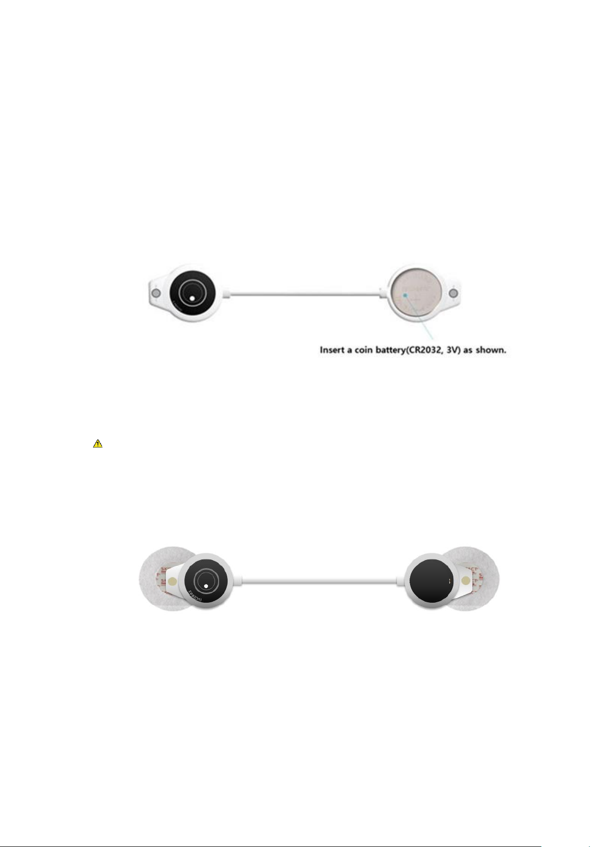
3) Insert battery to main body 1 of S-PATCH3-CARDIO.
First, release the screw on main body1 using screw driver.
Second, open the upper case of main body1 and insert the battery.
Lastly, close the case and lock the screw.
Caution ;
Do not replace the battery at extreme environment condition (Extremely high
temperature, high pressure, high humidity and Etc...)
Please contact to the manufacturer, if you need more information
to replace the battery.
4) Connect Electrodes to electrode connect hole in each side of S-PATCH3-CARDIO.
[10]
Page 11

3.4 Precautions
1) The electrodes and coin battery are disposable. Please observe local laws for disposal of
electrodes and coin battery.
2) To remove the battery if the S-PATCH3-CARDIO is not likely to be used for some time.
3) Please ensure user’s hands are clean and dry when handle the S-PATCH3-CARDIO
4) The body hair possibly causes contact problem which results a fault detection of
physiological data.
5) After using the device, wipe dust and other foreign substances using a dry cloth.
6) This product must not be disposed of with your other household waste. Instead, it is
your responsibility to dispose of your waste equipment by handing it over to a
designated collection point for the recycling of waste electrical and electronic
equipment. The separate collection and recycling of your waste equipment at the
time of disposal will help to conserve natural resources and ensure that it is recycled
in a manner that protects human health and the environment. For more information
about where you can drop off your waste equipment for recycling, please contact
your local city office, your household waste disposal service or the shop where you
purchased the product.
[11]
Page 12
4. Using and Operating S-PATCH3-CARDIO
S-PATCH3-CARDIO
4.1 How to Use S-PATCH3-CARDIO
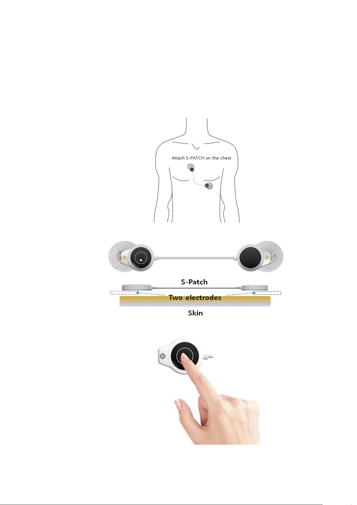
1) After connect the electrodes with S-PATCH3-CARDIO, peel the plastic on the backside
of the electrodes.
2) Attach the S-PATCH3-CARDIO on recommended position as drawn.
3) Push the power button longer than 3 seconds.
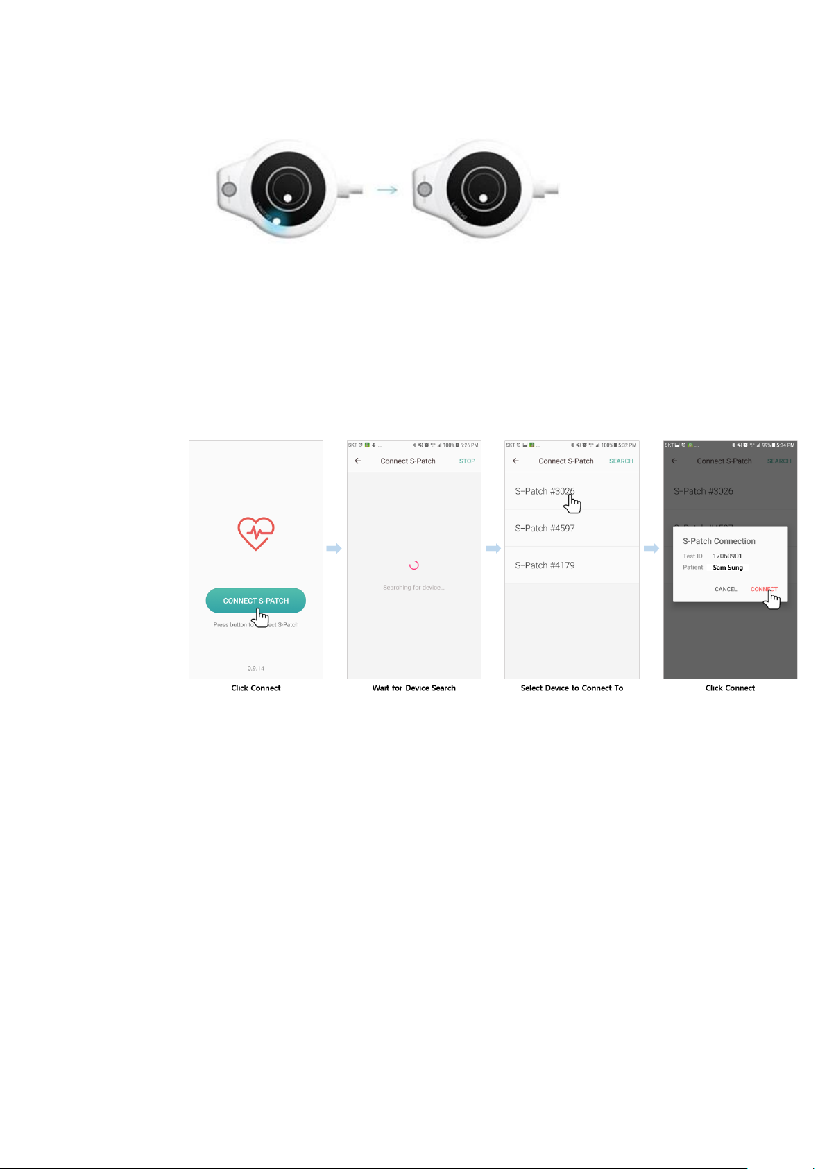
4) Confirm that the LED is ON and OFF 3 times.
[12]
Page 13
< ON > < OFF >
5) Put the Bluetooth mode to “ON” mode of user’s mobile device.
6) Please execute S-PATCH App
6-1) Open the App to see following sequence of screens:
6-2) Press “Connect S-Patch” button on lower center of screen.
6-3) Wait while the app searches for device.
6-4) Select device to connect.
6-5) Press “Connect” after confirming test sequence(test ID) and patient name (patient
ID).
[13]
Page 14
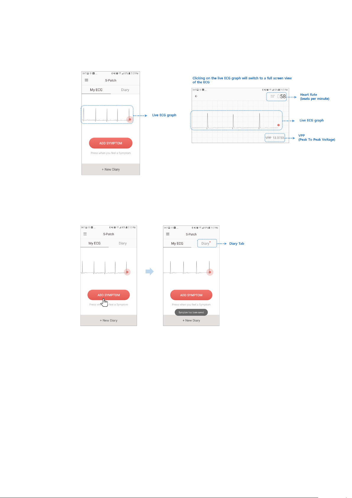
6-6) User’s ECG graph can be viewed from screen.
Clicking on the live ECG graph will pull up vertical screen for full screen view of ECG.
6-7) Press “Add Symptom” button to record any symptoms instantly. This button will
save a “not specified” symptom on diary tab to which user can add details at a later time.
After button is pressed “Symptom has been saved” message appears momentarily at
bottom of screen.
[14]
Page 15
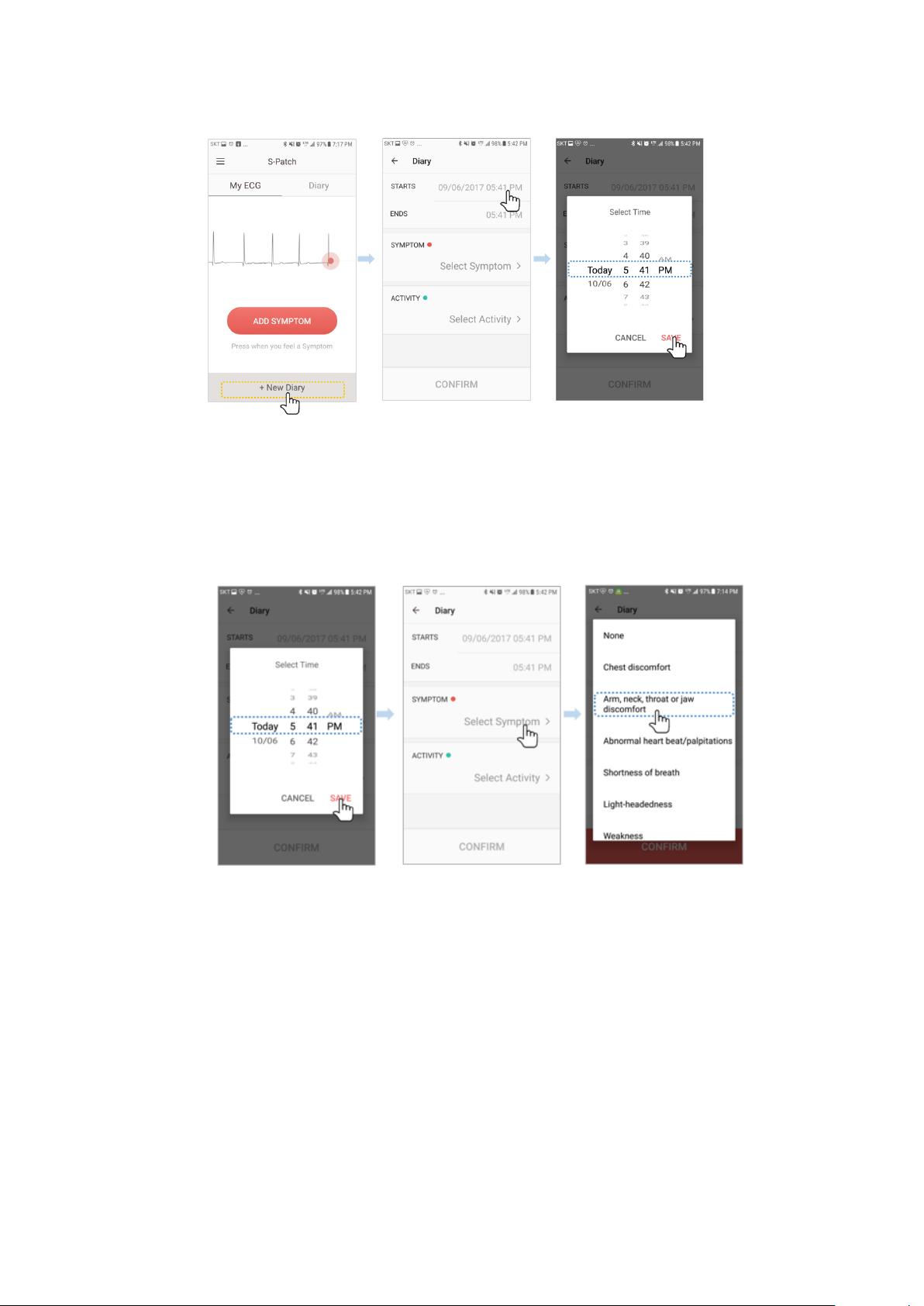
6-8) Press “+ New Diary” to create a new diary entry.
6-9) Enter start date and time of symptom.
6-10) Enter end date and time of symptom.
6-11) Press “Select Symptom” and select a symptom from list.
[15]
Page 16
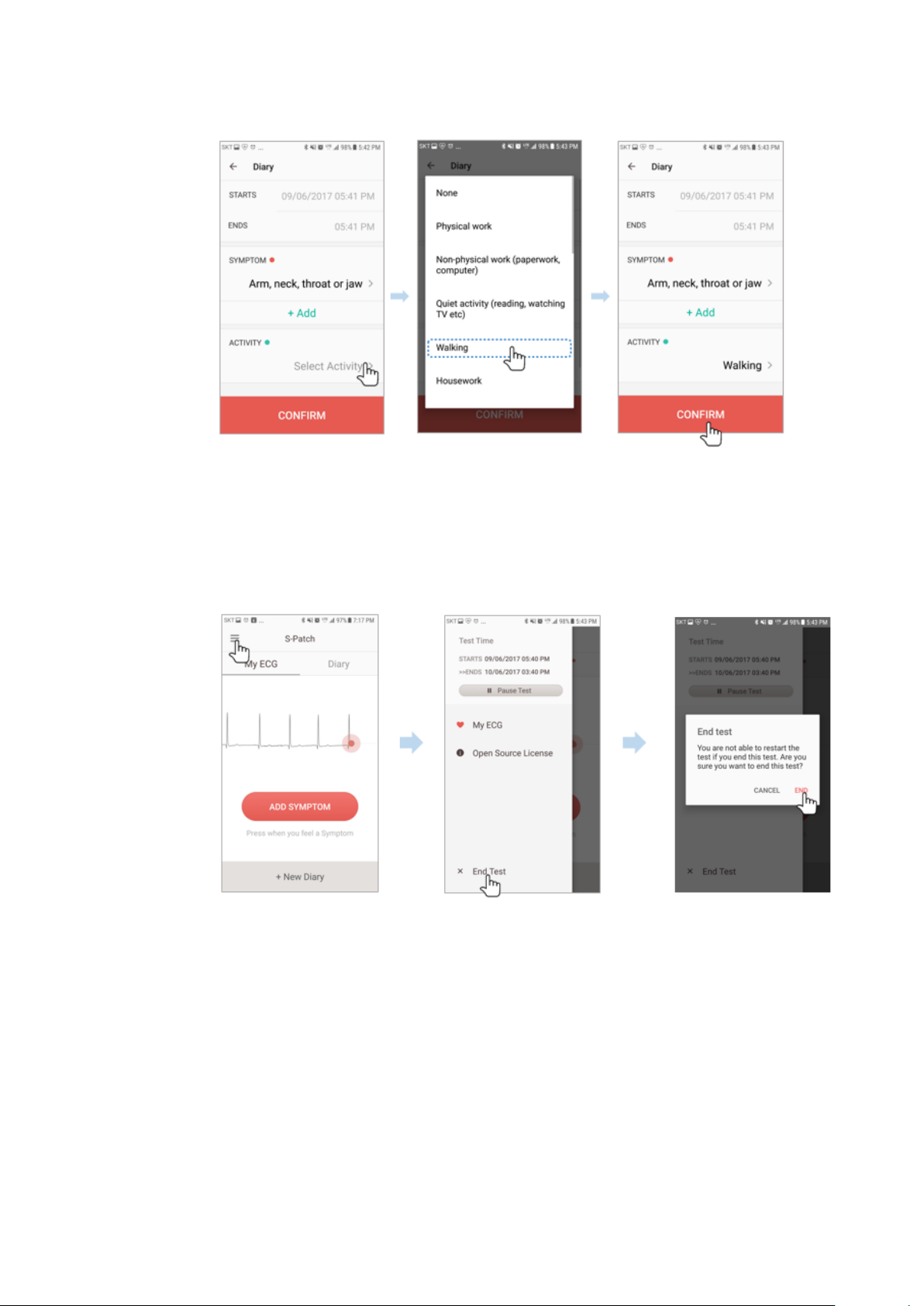
6-12) Press “Select Activity” and select an activity from list.
6-13) Press “Confirm” to save the new diary entry.
6-14) When the duration of test is over, test will automatically upload to cloud, but in
case user desires to end the test early press the menu button on upper left of screen.
6-15) Press “End Test” on the bottom of menu options.
6-16) An “End test” message will appear and user can press “End” to end the test.
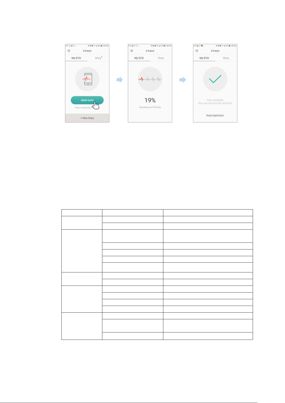
6-17) When manually ending the test, the test data also requires manual sending. After
the test is ended, screen will change to send data screen.
[16]
Page 17
Classification
Name
Description
Performance
Type
CF-Type
Channel
Single channel
Circuitry
Communication with
Mobile device
Bluetooth
DC Offset Tolerance
+/- 300mV
ADC Resolution
12 bits
ADC Sampling Rate
1000 Samples/Second
Input Impedance
>100 MΩ
Power
Requirements
Power Supply
3 Vd.c. (Lithium coin battery)
Battery Life
120 Hr.
Software
F/W version
V1.00
CPU
S1SBP6A (Cortex-M4F microprocessor)
BLE
Dialog DA14583(ARM Cortex-M0)
App(Android)
Kitkat(API19) or later
Physical
Characteristics
Weight (Exc. Battery)
8g
Dimension(Main Body1,2)
29*5.5(mm), 29*4.4(mm) [Diameter*
Height]
Dimension(Connect Cable)
110 ± 10 (mm)
4.2 Specifications
6-18) Press “Send Data” button on lower center of screen (requires internet connection).
6-19) Wait for app to finish transmitting data.
6-20) Click “Reset Application” to prepare the app for next S-Patch test.
4.2.1 S-PATCH3-CARDIO Specifications
[17]
Page 18

4.3 Error Message
Error
Message
Situation
Solution
The server
encountered
an error
When an error has occurred at server and the
mobile request cannot be executed
Contact service desk and
enquire.
No data to
send
When no data has been recorded because there
is an error with time of gateway device and the
test ends as soon as it has been started
Reinstall App
Failed to
connect to
service
When mobile device cannot access server due
to network error
Re-try after moving to
area with LTE or Wifi
connection
4.4 Maintenance
For cleaning, gently wipe with a soft dry cloth after using the S-PATCH 3. Please attempt to keep SPATCH3-CARDIO dust free. S-PATCH is waterproof. But it should be kept dry. This device does not
have serviceable components.
Do not disassemble, crush, puncture, short external contacts or circuits, dispose of in fire or water.
4.5 Specification of External Device connection
The S-Patch3 is connected to the Android Application. The data indicating the status of the device is
transmitted to the application from the device.
A. The required specification of the interface and IT -Network that combines PEMS
1) Main Device / Mobile App interface
Data format: Bluetooth
Mobile Application: Application on based Android
Device status information
Device information (Bringing information when connecting to BLE)
Battery information (Receiving information periodically)
Data to Device – Data Channel
Transmits the data to the device
B. Technical specification about network connection of PEMS including security features.
1) Mobile Application is designed to not-affect by an external virus infiltration. But if infected with
virus, Operating System may be a loss of storage data. Therefore, in the case of virus infection it
should be operated by an antivirus program.
2) Specification of Network connection
Communication protocol: the protocol between the main unit and the mobile app is a BLE
central (Mobile) – peripheral (main unit) communications and they communication with security
requirements defined in the BLE Protocol Stack.
C. Responsibility Organization
– connection of the PEMS to an it-network that includes other equipment could result in
previously unidentified risks to patients, operators or third parties;
– the responsible organization should identify, analyze, evaluate and control these risks;
– subsequent changes to the it-network could introduce new risks and require additional
analysis; and
– changes to the it-network include:
• changes in the it-network configuration;
• connection of additional items to the it-network;
• disconnecting items from the it-network;
• update of equipment connected to the it-network; and
• upgrade of equipment connected to the it-network.
[18]
Page 19
5. Heart Rate Algorithm
5.1 HR calculation per beat
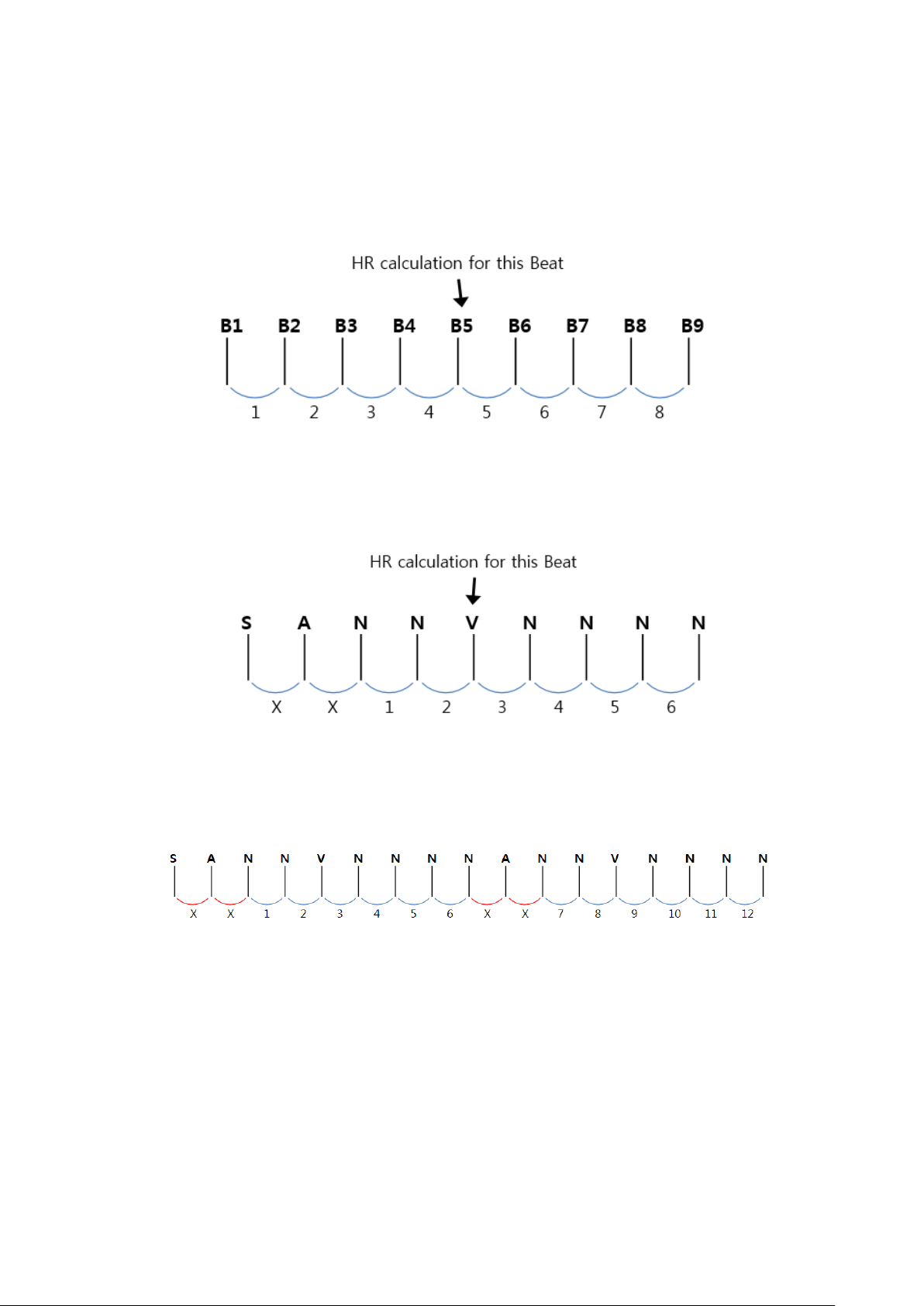
When calculating HR of each beat, 9 beats including previous 4 beats and following 4 beats are
required.
Number of effective sections / (( time of B9 – time of B1 ) / 60 )
Definition of “section” is the interval between consecutive beats such as B1 and B2, and in case 1 of the 2 beats
is A ( Artifact ) , exclude it from effective section. If there are less than 5 effective sections, no calculation.
As the above picture, if beats S A N N V N N N N are within a section of 5 seconds and the excluded section is
1 second, the V beat in the center will have HR value of 6 / ((5-1) / 60) = 91 bpm.
5.2 Average HR calculation of a section
Average HR of a section is calculated with the beats included in the section.
If the above data is within a 20 second frame, the average HR is calculated as follows:
Number of effective sections / (( Total length of effective sections ) / 60 )
At this time, “section” refers to the interval between consecutive beats such as B1 and B2, and in case 1 of the 2
consecutive beats is A ( Artifact ) , exclude it from effective section before calculation.
Therefore, there are 12 effective sections, and if the total length of invalid sections is 2 seconds , the average is
calculated as follows:
12 / ((20-2) / 60) = 40 bpm
[19]
Page 20
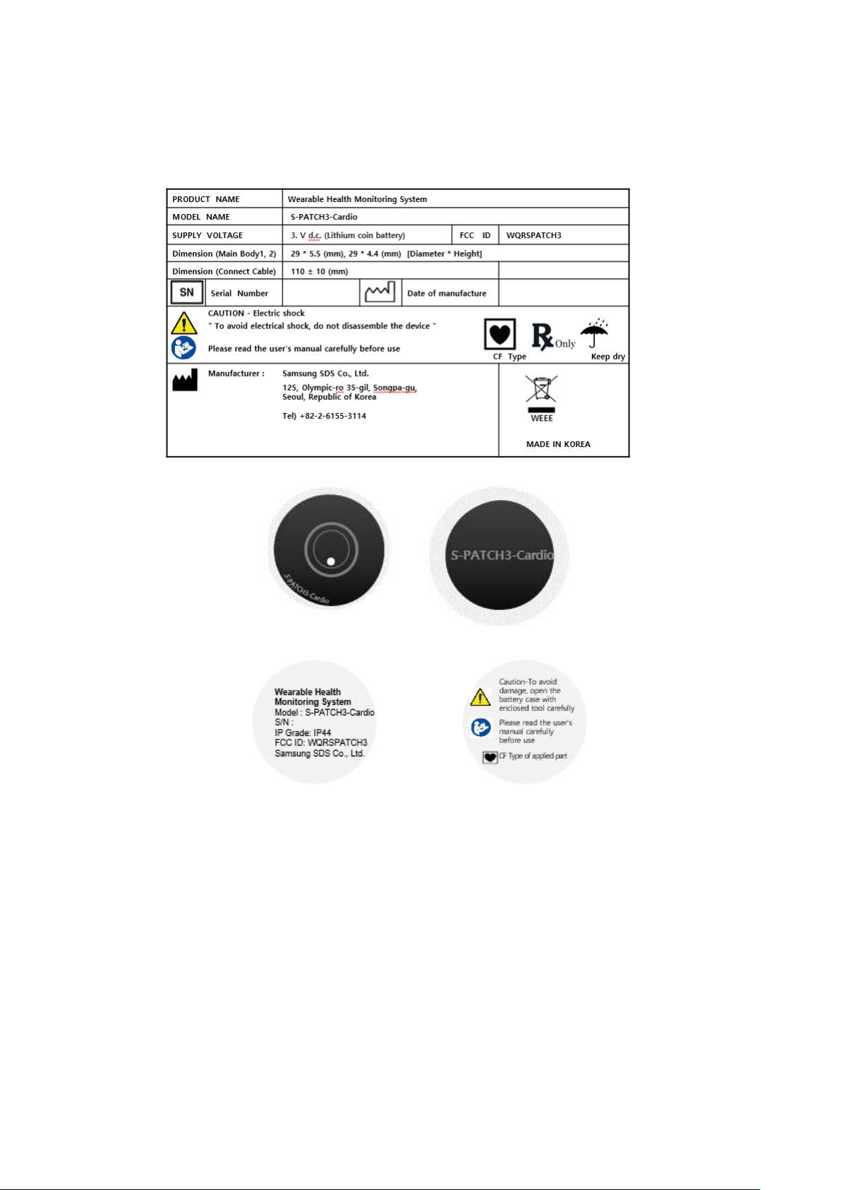
6. Labels and Packaging
6.1 Labels
6.1.1 Label for Packaging
6.1.2 Label for module
Front- side 2 Labels
Rear-side 2 Labels
[20]
Page 21
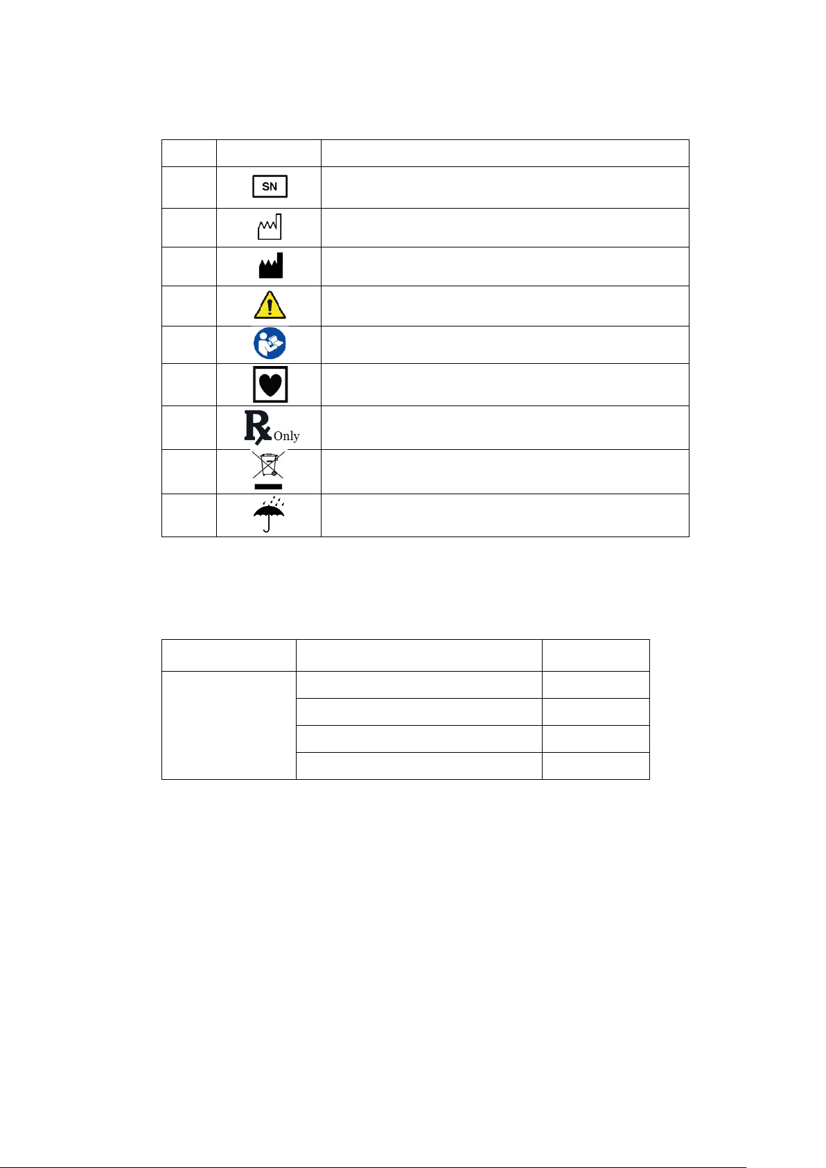
Label
Symbol
Description
1
The serial number that identifies the object.
2
Date of manufacture
3
Manufacturer
4
Caution / Warning
5
Instruction for User Manual
6
Type of applied part
7
Prescription only
8
WEEE Mark
9
Keep Dry
Classifications
Components
Quantity
Main Box
S-PATCH3-CARDIO module
1
Electrodes
4
Battery
1
Manual
1
- Descriptions on the visual symbols of the label
6.2 Packaging
6.2.1 Package List
6.2.2 Package Units
1) S-PATCH3-CARDIO module
Main module.
2) Electrodes
4 Electrodes are in the 1 plastic bag.
3) Battery
1 Coin Cell battery is shipped at package.
4) Manual
[21]
Page 22

Immunity test
Compliance
Electromagnetic environment - Guidance
RF Emissions
CISPR 11
Group 1
The S-PATCH3 uses RF energy only for its internal
function. Therefore, its RF emissions are very low and are
not likely to cause any interference in nearby electronic
equipment
RF Emissions
CISPR 11
Class B
The S-PATCH3 is suitable for use in ail establishments,
including domestic establishments and those directly
connected to the public low-voltage power supply network
that supplies buildings used for domestic purposes
Immunity test
IEC 60601
Test level
Compliance level
Electromagnetic environment -
Guidance
Electrostatic
discharge (ESD)
IEC 61000-4-2
±8kV Contact
±2,4,8,15 kV air
±8kV Contact
±2,4,8,15 kV air
Floors should be wood, concrete
or ceramic tile. If floors are
covered with synthetic material,
the relative humidity should be at
least 30%.
7. Information on EMC
7.1 Guidance and Manufacturer’s Declaration – Electromagnetic Emissions
- The EUT is intended for use in the electromagnetic environment specified below. The
customer or the user of the EUT should assure that it is used in such an environment.
7.2 Guidance and Manufacturer’s Declaration – Electromagnetic Immunity
- The EUT is intended for use in the electromagnetic environment specified below. The
customer or the user of the EUT should assure that it is used in such an environment.
[22]
Page 23
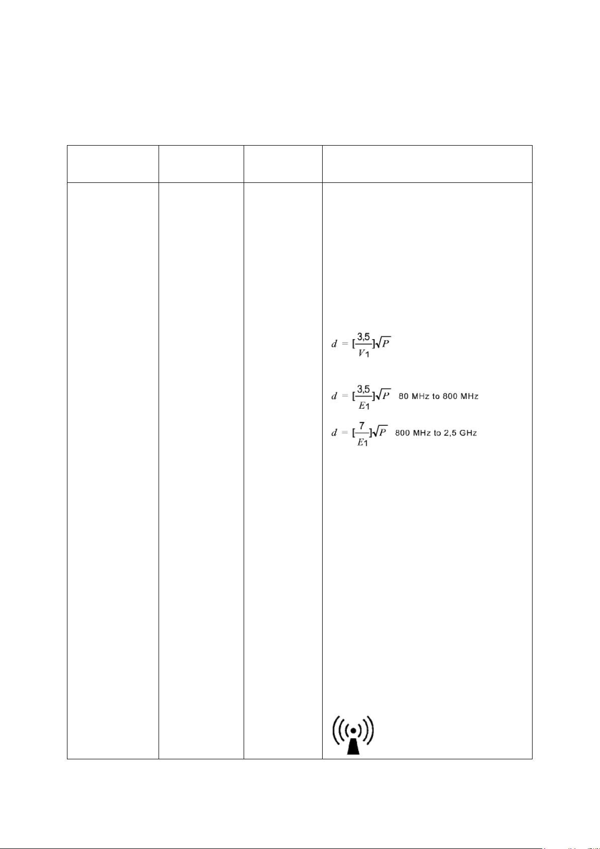
Immunity test
IEC 60601 Test
level
Compliance
level
Electromagnetic environment - Guidance
Conducted RF
IEC 61000-4-6
Radiated RF
IEC 61000-4-3
3 V
0,15 MHz – 80
MHz
6 V in ISM and
amateur radio
bands between
0,15 MHz and
80 MHz
80 % AM at 1
kHz
10 V/m
80 MHz – 2,7
GHz
80 % AM at 1
kHz
3 V
0,15 MHz – 80
MHz
6 V in ISM
and amateur
radio
bands between
0,15 MHz and
80 MHz
80 % AM at 1
kHz
10 V/m
80 MHz – 2,7
GHz
80 % AM at 1
kHz
Portable and mobile RF communications
equipment should be used no closer to any
part of the S-PATCH3, including cables,
than the recommended separation distance
calculated from the equation applicable to
the frequency of the transmitter.
Recommended separation distance
where P is the maximum output power
rating of the transmitter in watts (W)
according to the transmitter manufacturer
and d is the recommended separation
distance in meters (m).
Field strengths from fixed RF transmitters,
as deter-mined by an electromagnetic site
survey, a
should be less than the compliance level in
each frequency range. b
Interference may occur in the vicinity of
equipment marked with the following
symbol :
7.3 Guidance and Manufacturer’s Declaration – Electromagnetic Immunity
- The EUT is intended for use in the electromagnetic environment specified below. The
customer or the user of the EUT should assure that it is used in such an environment.
[23]
Page 24
NOTE 1) At 80MHz and 800MHz, the higher frequency range applies.
NOTE 2) These guidelines may not apply in all situations. Electromagnetic propagation is
affected by absorption and reflection from structures, objects and people.
a
Field strengths from fixed transmitters, such as base stations for radio (cellular/cordless) telephones
and land mobile radios, amateur radio, AM and FM radio broadcast and TV broadcast cannot be
predicted theoretically with accuracy. To assess the electromagnetic environment due to fixed RF
transmitters, an electromagnetic site survey should be considered. If the measured field strength in the
location in which the EUT is used exceeds the applicable RF compliance level above, the EUT should
be observed to verify normal operation. If abnormal performance is observed, additional measures
may be necessary, such as re-orienting or relocating the EUT.
b
Over the frequency range 150kHz to 80MHz, field strengths should be less than [V1] V/m.
Rated maximum output
power of transmitter
[W]
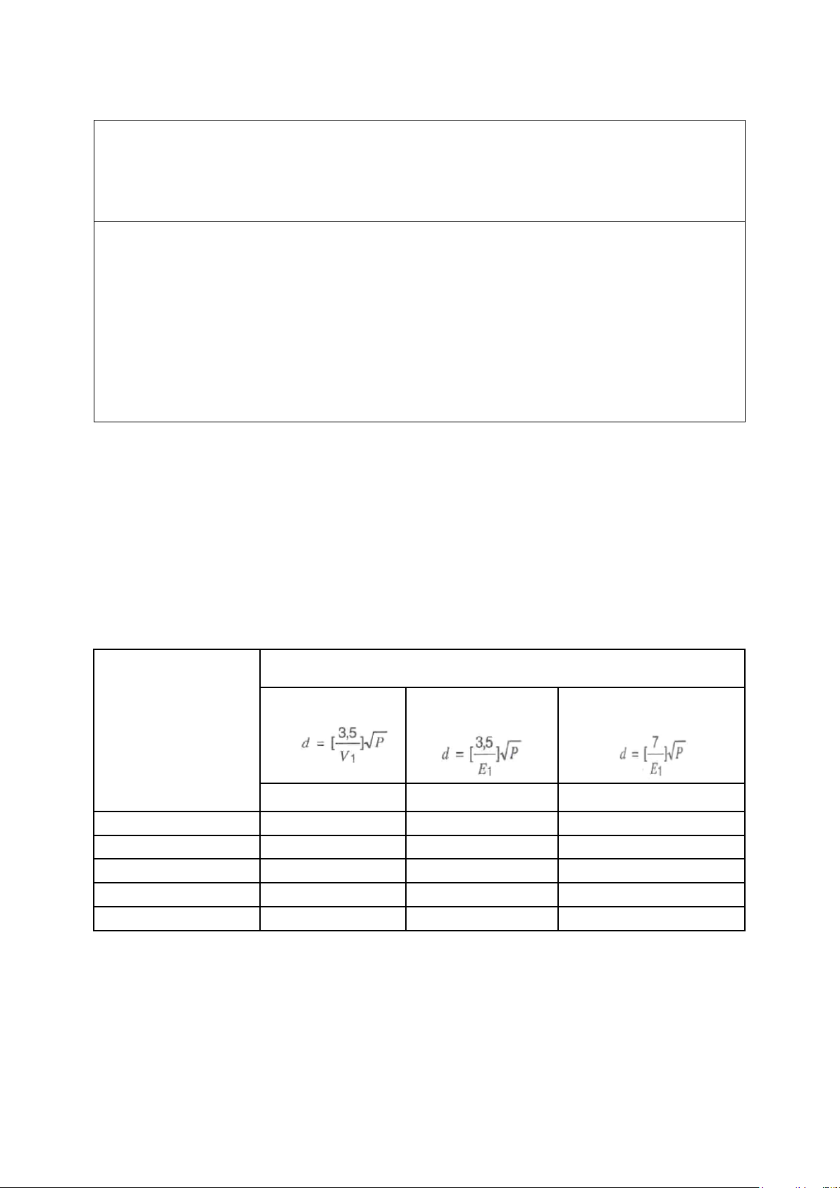
Separation distance according to frequency of transmitter [m]
150kHz to 80MHz
80MHz to
800MHz
800MHz to
2.5GHz
V1=3Vrms
E1=3V/m
E1=3V/m
0.01
0.116
0.1166
0.2333
0.1
0.368
0.3687
0.7378
1
1.166
1.1660
2.3333
10
3.687
3.6872
7.3785
100
11.660
11.6600
23.333
7.4 Recommended separation distances between portable and mobile RF communications
equipment and the EUT
- There is intended for use in an electromagnetic environment in which radiated RF
disturbances are controlled. The customer or the user of the EUT can help prevent
electromagnetic interference by maintaining a minimum distance between portable and
mobile RF communications equipment (transmitters) and the EUT as recommended
below, according to the maximum output power of the communications equipment.
[24]
Page 25
For transmitters rated at a maximum output power not listed above, the recommended separation
distance d in meters (m) can be estimated using the equation applicable to the frequency of the
transmitter, where p is the maximum output power rating of the transmitter in watts (W) according to
the transmitter manufacturer.
NOTE 1) At 80MHz and 800MHz, the separation distance for the higher frequency range applies.
NOTE 2) These guidelines may not apply in all situations. Electromagnetic propagation is affected by
absorption and reflection from structures, objects and people.
Immunity test
IEC 60601 Test Level
Actual Immunity Level
Compliance Level
Radiated RF
IEC 61000-4-3
10V/m
80MHz - 2.7GHz
80 % AM at 1 kHz
10V/m
10V/m
7.5 Immunity and Compliance Level
[25]
Page 26
Immunity test
IEC 60601
test level
Compliance
level
Electromagnetic environment - Guidance
Conducted RF
IEC 61000-4-6
Radiated RF
IEC 61000-4-3
3 V
0,15 MHz – 80
MHz
6 V in ISM and
amateur radio
bands between
0,15 MHz and
80 MHz
80 % AM at 1
kHz
10 V/m
80 MHz – 2,7
GHz
80 % AM at 1
kHz
3 V
0,15 MHz –
80 MHz
6 V in ISM
and amateur
radio
bands
between 0,15
MHz and
80 MHz
80 % AM at
1 kHz
10 V/m
80 MHz – 2,7
GHz
80 % AM at
1 kHz
The EUT must be used only in a shielded
location with a minimum RF shielding
effectiveness and, for each cable that enters
the shielded location with a minimum RF
shielding effectiveness and, for each cable
that enters the shielded location
Field strengths outside the shielded location
from fixed RF transmitters, as determined
by an
electromagnetic site survey, should be less
than 3V/m.
a
Interference may occur in the vicinity of
equipment marked with the following
symbol:
NOTE 1) These guidelines may not apply in all situations. Electromagnetic propagation is affected by
absorption and reflection from structures, objects and people.
NOTE 2) It is essential that the actual shielding effectiveness and filter attenuation of the shielded
location be verified to assure that they meet the minimum specification.
a
Field strengths from fixed transmitters, such as base stations for radio (cellular/cordless) telephones
and land mobile radios, amateur radio, AM and FM radio broadcast and TV broadcast cannot be
predicted theoretically with accuracy. To assess the electromagnetic environment due to fixed RF
transmitters, an electromagnetic site survey should be considered. If the measured field strength
outside the shielded location in which the EUT is used exceeds 3V/m, the EUT should be observed to
verify normal operation.
If abnormal performance is observed, additional measures may be necessary, such as relocating the
EUT or using a shielded location with a higher RF shielding effectiveness and filter attenuation.
7.6 Guidance and Manufacturer’s Declaration – Electromagnetic Immunity
- The EUT is intended for use in the electromagnetic environment specified below. The
customer or the user of the EUT should assure that it is used in such an environment.
[26]
Page 27

8 FCC Compliance Statement
This device complies with part 15 of the FCC rules. Operation is subject to the following two
conditions:
(1) This device may not cause harmful interference, and
(2) This device must accept any interference received, including interference that may
cause undesired operation.
This equipment has been tested and found to comply with the limits for a Class B digital device
pursuant to part 15 of the FCC rules. These limits are designed to provide reasonable protection
against harmful interference in a residential installation. This equipment generates, uses and
can radiate radio frequency energy and, if not installed and used in accordance with the
instructions, may cause harmful interference to radio communications. However, there is no
guarantee that interference will not occur in a particular installation. If this equipment does
cause harmful interference to radio or television reception, which can be determined by turning
the equipment on and off, the user is encouraged to try to correct the interference by one or
more of the following measures:
● Reorient or relocate the receiving antennae
● Increase the separation between the equipment and the receiver
● Connect the equipment into an outlet on a circuit different from that to which the
receiver is connected.
● Consult the dealer or an experienced radio/TV technician for help.
FCC RF Exposure Statement
This equipment complies with FCC radiation exposure limits set forth for an uncontrolled
environment. End users must follow the specific operating instructions for satisfying RF
exposure compliance. The antenna used for this transmitter must not transmit simultaneously
with any other antenna or transmitter, except in accordance with FCC multi-transmitter product
procedures.
FCC Caution
Any changes or modifications to the equipment not expressly approved by the party responsible
for compliance could void user’s authority to operate the equipment.
9 Expected Service Life time and Warranty
9.1 Expected Service Life Time
- S-PATCH3-CARDIO is guaranteed to last for a minimum of two years.
9.2 Product Warranty
- The warranty covers a year.
However, the conditions excluded by the warranty are as follows.
Natural aging of the product from daily usage
[27]
Page 28

Product damage due to improper storage
Product damage due to improper usage
10 Company Introduction
10.1 Company Name and Address
Company name: Samsung SDS Co., Ltd.
Address: 125, Olympic-ro 35-gil, Songpa-gu, Seoul, Republic of Korea
Tel: +82-2-6155-3114
10.2 EC Representative
Name: Samsung SDS Europe
Address: KT13 0NY, 1st Fl. No. 5, The Heights, Brooklands Weybridge
Surrey, United Kingdom
Contacts:
Phone: +44-7825-035-687
Fax: N/A
[28]
 Loading...