

Samsung SP0411N, SP0311N, SP0221N Service Manual
PANGO(PL40) Series
Model:
SP0221N
SP0311N
SP0411N
HARD DISK DRIVE service manual
Hard Disk Drive
Contents
1. Specification summary
2. Block Diagram of HDD
3. Connector & Jumper Pin Assignments
4. Exploded View
5. Maintenance Cylinder Configuration
6. How to use LEO Program
7. How to progress Burn-In Test
8. Caution
Attachment
related HDD
Attachment
Attachment
1. The basic information
2. HDD related terms
3. Q&A

SAMSUNG HARD DISK DRIVE
1. Specification Summary
Items Specification Remarks
Voltage Requirement DC +12V/±10%, DC +5V/±5%
Interface ATA - 6
SP0221N - 20.0GB (1CH)
Capacity
Disk / Head
Features
Seek Time
(RD/WT typical)
RPM 7,200 ± 0.35 % RPM
Temperature
(Operating)
Track to Track : 1.0 / 1.2 ms
Average : 10.0 / 12.0 ms
Full Stroke : 17.5 / 19.0 ms
SP0311N - 30.0GB (1CH)
SP0411N - 40.0GB (1CH)
SP0221N - 1/1(disk/head)
SP0311N - 1/1(disk/head)
SP0411N - 1/1(disk/head)
S.M.A.R.T Compliant
Buffer size 2 Mbytes
MTBF(POH) 500,000 hours
5~55°C
UDMA133supporting
MA100 Default)
(UD
Humidity
(Operating)
Temperature
(Non-operating)
Humidity
(Non-operating)
Linear Shock
(Operating)
Linear Shock
(Non-operating)
PANGO(PL40)
5~90%
-40~+70°C
5~95%
63 G @2.0ms Linear Shock
350 G (2ms linear shock)
Non-condensing
2
SAMSUNG HARD DISK DRIVE
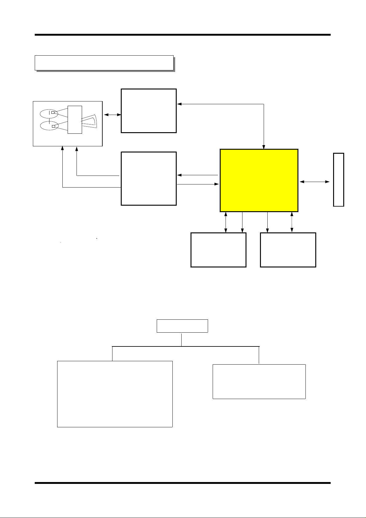
2. Block Diagram of HDD
PREAMP &
WRITE DRIVER
Marvell
81G5122
HDA
SPINDLE MOTOR &
ACTUATOR COMBO
DRIVER
HA13627
HDD
Flash 1Mbit
M29F102BB
AT Controller
R/W Channel
Servo Controller
Dual-DSP
88I6522
Buffer 16Mbit
EM636165TS-6
A
T
A
B
U
S
HDA (HEAD DISK ASSEMBLY)
-HEAD
-DISK
- VCM (Voice Coil Motor)
- SPM (Spindle Motor)
PANGO(PL40)
PCBA (PCB ASSEMBLY)
-PCBA
3
SAMSUNG HARD DISK DRIVE
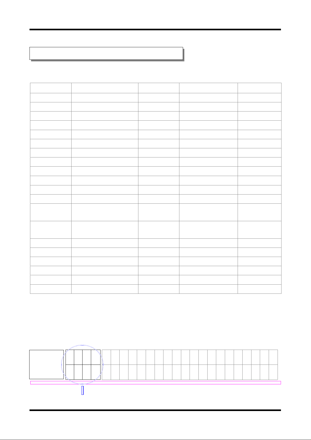
3. Connector / Jumper Pin Assignment
●
40 Pin I/O Connector Interface Signals
Number Signal Number Signal Remarks
1 RESET- 2 GND
3 DD7 4 DD8
5 DD6 6 DB9
7 DD5 8 DB10
9 DD4 10 DB11
11 DD3 12 DB12
13 DD2 14 DB13
15 DD1 16 DB14
17 DD0 18 DB15
19 GND 20 Key Pin
21 DMARQ 22 GND
23 DIOW - : STOP 24 GND
25 DIOR - : HDMARDY
27 IORDY : DDMARDY
29 DMACK 30 GND
31 INTRQ 32 IOCS16
33 DA1 34 PDIAG - : CBLID 35 DA0 36 DA2
37 CS0- 38 CS139 DASP- 40 GND
●
Jumper Pin Assignment
+GG+
12NN5
VDDV
JUMPER PIN
26 GND
: HSTROBE
28 CSEL
:HSTROBE
PCBA components side
oooo
PANGO(PL40)
2468
1357
246810121416182022242628303234363840
13579111315171921232527293133353739
HDA BASE
4
SAMSUNG HARD DISK DRIVE
②④⑥⑧
①③⑤⑦
M
S
C
S
A
L
S
T
S
A
E
T
V
L
E
E
R
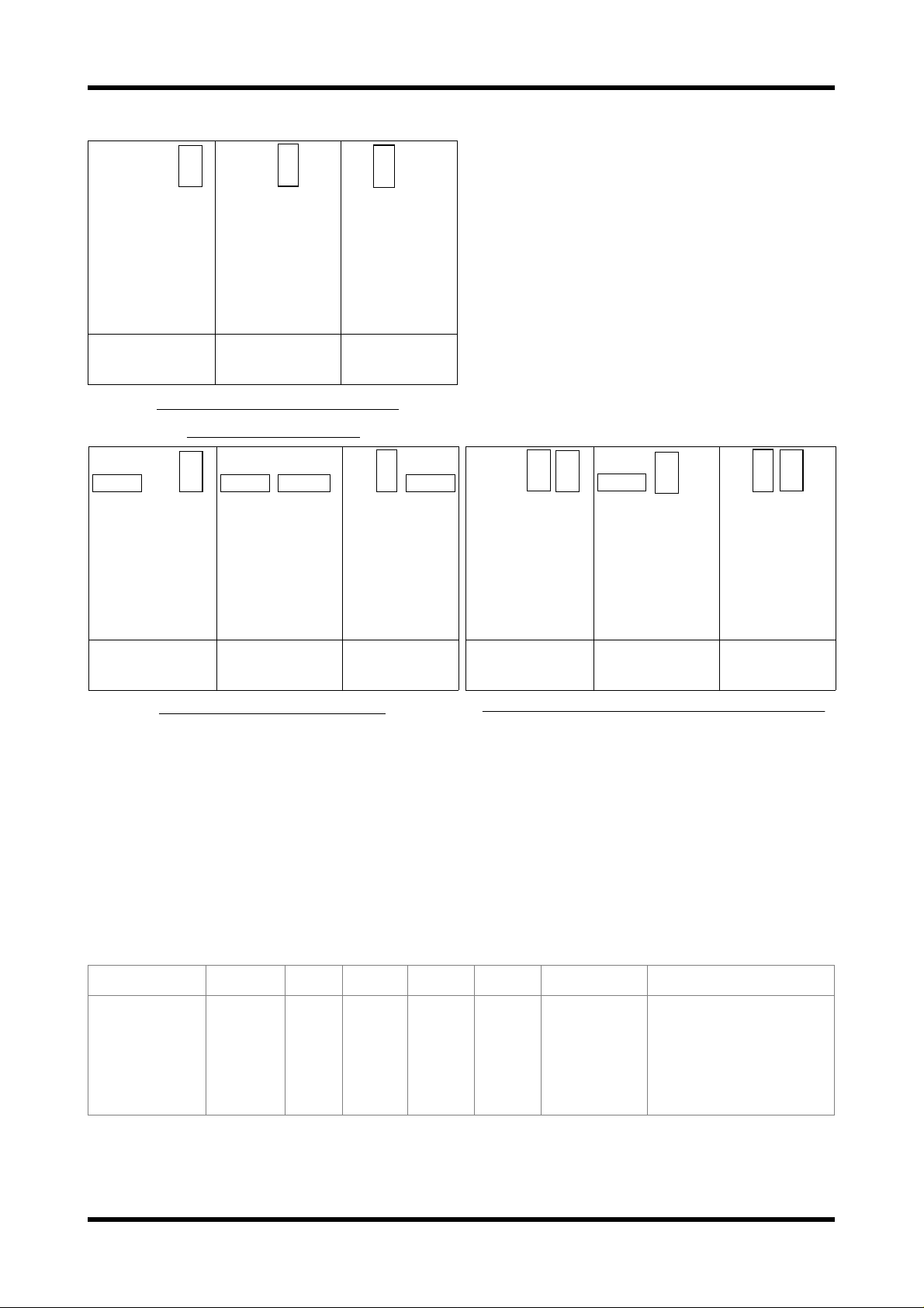
MASTER
(1DRIVE)
< Jumper Pin Setting for
SP0221n,SP0311N>
②④⑥⑧
①③⑤⑦
M
S
C
S
A
L
S
T
S
A
E
T
V
L
E
E
R
MASTER
(1DRIVE)
②④⑥⑧
①③⑤⑦
S
C
S
S
T
E
L
SLAVE
②④⑥⑧
①③⑤⑦
C
S
S
T
E
L
SLAVE
M
L
A
A
S
V
T
E
E
R
S
M
L
A
A
S
V
T
E
E
R
②④⑥⑧
①③⑤⑦
M
S
C
S
A
L
S
T
S
A
E
T
V
L
E
E
R
CABLE
SELECT
②④⑥⑧
①③⑤⑦
M
S
C
S
A
L
S
T
S
A
E
T
V
L
E
E
R
CABLE
SELECT
②④⑥⑧
①③⑤⑦
M
S
C
S
A
L
S
T
S
A
E
T
V
L
E
E
R
MASTER
(1DRIVE)
②④⑥⑧
①③⑤⑦
S
C
S
T
S
E
L
SLAVE
M
L
A
A
S
V
T
E
E
R
②④⑥⑧
①③⑤⑦
M
S
C
S
A
L
S
T
S
A
E
T
V
L
E
E
R
CABLE
SELECT
< Setting for SP0411N >
●
BIOS Setup Parameter
모델구분
SP0221N
SP0311N
SP0411N
CYL HD PRE LZ SEC SIZE
38,870
58,246
77,622
16
16
16
< 32GB Capacity Limit of PC/BIOS >
비고
X
X
X
X
X
X
63
63
63
20.0 GB
30.0 GB
40.0 GB
39,180,960
58,711,968
78,242,976
PANGO(PL40)
5
SAMSUNG HARD DISK DRIVE
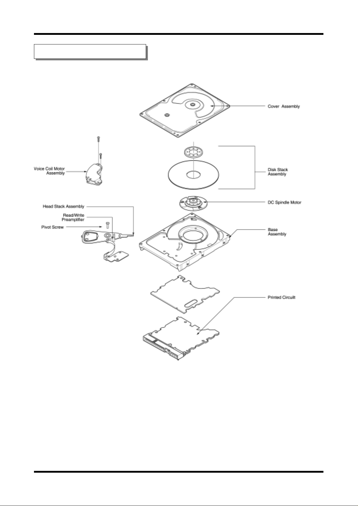
4. Exploded View
PANGO(PL40)
6

SAMSUNG HARD DISK DRIVE
<< Major components of HDD >>
HDD is formed by major components as follows: Base, Cover, ARM(E-Block), Latch, Crash Stop,
Pivot Bearing, Breather Filter, Window Clock, Window Push Pin, Jump Pin, Spindle Motor,
Actuator, Magnetic Head, Magnetic Disk, PCBA
① Base
Base could be a basic frames for HDD assembly. Spindle motor, ARM, VCM, cover and PCBA
are assembled on it, and other components are sub-assembled on those configuration.
ARM and Spindle motor assembled to Head and Disk each in advance,then those are assembled
on Base. If base could be effected by external and internal vibration (spindle motor
& actuator's fake vibration), relative displacement occurred between head and disk so to
reduce this effect to PES(Position Error Signal) and data signal, shape design concerned
mode shaping should be needed.
② Cover
Cover protect HDD components from the exterior impact and play role of sealing to cut off
particle and moisture which could be a fatal factor to head and disk. Cover is also designed
in consideration of noise and vibration effect.
③ ARM (E-block)
ARM is assembled HGA and VCM coil back and forth and it is connected to pivot axis pivot
bearing. When VCM coil generate torque due to electromagnetic force of VCM, ARM swing around
pivot and play a role of carriage so as head may access to information side of disk.
Inertia
reach to the proper point on of HDD efficiency, is minimizing ARM's weight to decrease inertia.
And then to decrease weight of ARM, it'll be composed low density materials and reduce ARM's
size within safety allowed when designed.
Unbalance
unbalance occur and it caused ARM to torque.
And acceleration might affect on unbalance mass in condition impact or vibration are given
from the exterior. In case of magnetic latch, this unbalance could be a reason that latch
released. Therefore shape simulation of ARM should be designed lest the center of gravity
should go off center of revolving.
④ Latch
When power HDD off, spindle motor stop spinning and park at parking zone automatically
according to the order systemized. By that time if head is given any impact or vibration
from the exterior, head invade data zone clung to disk. And then data damaged consequently,
Latch solve the problem above as maintain the regular distance of ARM.
: It is the best way to shorten data access time that shows how fast head can
: If the center of gravity for ARM isn't the same with that of pivot center,
PANGO(PL40)
7

SAMSUNG HARD DISK DRIVE
⑤ Crash Stop
Crash stop is made of elastic material and weaken a impact of actuator in emergency condition,
head getting out of data zone when it move to parking zone or seek.
⑥ Pivot Bearing
Pivot bearing is a roll bearing fixed the center of gyration of ARM. Inner Race is fixed by
screw after being connected to Base pivot and outer Race is fixed by retaining ring after
being connected by ARM's hole and make the ARM's revolving movement actively.
⑦ Breather Filter
In the interior of HDD, air flow is formed by the spinning disk in high speed and pressure
distribution occurred. This pressure is lower than atmospheric pressure of the exterior of
HDD and due to this, the outside air inflow into the interior caused contamination.
Breather filter fixed in inflow plug induce clean air and help air circulation.
⑧ Window Clock
Head must know the data's location information to access data on disk. Servo write is
a process of recording information disk. To record information, we make hole that head
for servo write can enter the interior of HDD and this hole is window clock.
This hole is closed with sealing label after done servo writing, be careful not to be
occurred inner contamination due to label's injury.
⑨ Window Push Pin
Head should be controlled to move on disk at a regular track pitch interval rate during
servo writing. ARM is torqued by VCM continuously and was controlled each track's moving
using push pin. Window push pin is a hole for this, the pin could enter interiorofHDA
and be careful contamination caused by label's injury because this hole is closed by sealing
label after done servo writing.
⑩ Jump Pin
During installing, HDD need setting of pin organization in the next according to
the drive running mode: master drive in single system, master drive in dual system,
slave drive in dual system.
⑪ Spindle Motor
Spindle motor is a sort of small motor which can change electric energy to mechanical energy
utilizing for magnetic field. When the current of stator's coil formed by electromagnet
is on, magnetic power occur between stator and rotator. (repeal occur between same pole and
attract occur in case of different pole) This power can make rotator revolve and we should
keep on changing the magnetic pole of the stator to maintain rotate at regular speed.
To progress this function, we deduct rotation speed and circuit for controlling needed.
It is possible to control the current flow and time interval with Hall element and MR
PANGO(PL40)
8

SAMSUNG HARD DISK DRIVE
element (these are sensitive to voltage change). The magnetic disk of hard disk is running
by DC Brushless direct drive motor directly. Brush has long life and high reliability
because it doesn't have belt. Recently we use flat motor to be adopted to the request of
minimizing. The rotation bearing is supported by Fluid Dynamic Bearing(FDB), this is not
keeping high speed spinning but also reducing resistance even eliminating and this make the
acceleration better.
The life of hard disk is up to the durability of this bearing supporting revolving axis.
Spindle motor rotate a disk media at regular speed.This device start to rotate as soon as
put power on and no matter what HDD read or write data,spindle motor always revolve.
Besides accurate reading from the media point of view is possible when maintain the constant
speed within 0.1%,rotation error. The control circuit of spindle motor receive the index data
from the spindle motor or media at every spin and check whether constant speed persists or not
then revise the speed. Spindle motor is applied to DC brushless motor.
⑫ Actuator
Hard disk has 2 disks so it has 4 written sides, and each side needs each written replay
device, 8 heads needed. This 4 heads can't work independently. Each head is connected with
one carriage and set as running altogether. For example, one head move at tenth track and
then the rest come to move at the same track. Retrieval(information searching) is a moving
the head to track properly. The faster searching speed, the better for a quick access.
It is profitable to use voice coil motor for a fast searching speed. Making narrow
the width and interval of track is for HDD capacity improvement so we can build more tracks
on written side so searching movements in head become subtle. Therefore servo control the
decision of HDD location. Magnetic disk is put standard signal for location marking from the
manufacturing step. Head read this to find the relative difference then run motor mediate
the head's location.
⑬ Magnetic Head
Magnetic field is formed around the conduct on passing electric current to conductor and
the direction and size of magnetic field are decided by those of an electric current.
Magnetic head build a minute gap in core (formed by ring) and pass an electric current then
strong magnetic leakage are occurred around gap thus magnetic particles of media vary the
direction according to the that of current: this is called recording. On the contrary, a
process induce magnetic signal to electric signal is called reading(decipherment).
⑭ Magnetic Disk
Recording carrier become a permanent magnet according to applying magnetic material to the
surface and change the magnetization direction of a electromagnet and it is possible to
store information during long term.
⑮ PCBA
PCBA is a circuit element concerning about HDD running and constructed in
engine IC,COMBO IC,read/write IC,ROM ,and sort of chip etc.
- Engine IC: contained RAM&Interface IC and exchange information to computer.
- COMBO IC: Controlling spindle motor & VCM running when HDD power on.
- Read/Write IC: read/write of HDD
PANGO(PL40)
9
SAMSUNG HARD DISK DRIVE
- ROM: Checking HDD basic function and management basic spec.
5.Maintenance Cylinder Configuration
Contents Disk Location sector size Header
CTBL 4, 0, 131 8 CHN_TB3
IDFY 0, 0, 1 1
IDFY 0, 0, 1 3
MLIST 0, 0, 6 1 MLIST
SRVTBL 0, 0, 7 3 SV_TBL
CONFIG 1, 0, 1 2 CONFIG
SNTBL 1, 0, 3 2
BISPT 1, 0, 5 4
BRSLT 1, 0, 10 1
FINALTST 1, 0, 12 8
FINALTST 1, 0, 19 8
CTBL 1, 0, 30 8 CHN_TBL
VLISTHDR 1, 0, 78 1 VLIST_H
VLIST 1, 0, 79 16
SLISTHDR 1, 0, 111 1 SLIST_H
SLIST 1, 0, 112 128
TLIST 1, 0, 368 4 TLIST
ALIST 1, 0, 372 8 RLIST
TMPRTR 1, 0, 395 2 TMPRTURE
MRTUNE 1, 0, 383 3 SV_TBL2
ARCOTBL2 1, 0, 387 8 CHN_TB2
LATCHFRC 4, 0, 4 1 LATCH_FC
BTIME 4, 0, 91 2 BI_TIME
ERRTRK 4, 0, 56 1 BER
ERRZN 4, 0, 57 1 BER1
ERRDRV 4, 0, 58 1 BER2
SRTDATA 4, 0, 59 1 ER_CNT
SRTSRVO 4, 0, 60 1 SV_ERCNT
PARAM 4, 0, 62 10
TSTPI 4, 0, 82 4 TPI_WRW
MRTUNEMT 4, 0, 86 5 MR_TUNE
DLIST 3, 0, 1 768
BPI 4, 0, 521 8 AZL_BPI
BPICSM 4, 0, 513 8 AZL_CSM
CURGEO 4, 0, 512 1 CUR_BPI
SMART 11, 0, 1 8 SMARTMEM
SEL 11, 0, 2 4
ELOG 12, 0, 1 768
RCOHDR 5, 0, 1 2 RCOHDR
RCODATA 5, 0, 1 256 RCODATA
SKEW 0, 0, 2 1 SKEW
CRITERIA 0, 0, 11 1
MRSKEW 0, 0, 189 1 MRSKEW
SMTBL 0,0,192 1 SM
UNITABLE 0, 0, 197 2 UNITABLE
SETMAX 0, 0, 233 1 SETMAX
D_CSM 3, 0, 2 252
WB_RLT 0, 1, 5 1 WB_RLT
GAIN 0, 0, 691 1 GAIN
WKHEAD 4, 0, 72 4 WK_HEAD
NPV 4, 0, 77 4
HIT 4,0,533 4
PANGO(PL40)
10

SAMSUNG HARD DISK DRIVE
7. How to use HUTIL Program
1) Before you start
HUTIL support from Voyager11P to VERNA series.(HUTIL 1.09 version)
(HUTIL has been upgrading constantly whenever new model comes out.)
- Preparation before use
Diskette or HDD containing HUTIL.EXE should be boot-up to MS-DOS mode,that is,
should be contained IO.SYS, MSDOS.SYS,COMMAND.COM (IO.SYS, MSDOS.SYS: hidden file).
And also HUTIL.CFG is required.
2) Explanation of each menu
OPTION - ABOUT HUTIL : Version of HUTIL.
OPTION - DOS SHELL : Execute DOS Shell. If you want back to HUTIL, input EXIT.
EXIT TO DOS : End HUTIL program.
OPTION - DRIVE INFORMATION : Open the information window about the target HDD.
Press ESC to close.
TEST - READ ALL: Display error list when error is occurred after reading whole cylinder.
Message will be appeared if the test time delay is over 20 seconds compared
with other normal HDD. In this case, HDD may have problem. (Progress
sequential read test from cyl. #0 to the last cylinder. No Defect Free.
- Refer to attachment below.)
TEST - READ FROM : Read from the designated cylinder and head to the last cylinder.
Press ESC to stop in the middle.
TEST - WRITE ALL: Write 00h on all cylinder except maintenance cylinder.
All data will be removed. (Even partition table, boot sector & FAT)
TEST - WRITE FROM : Write from the designate cylinder and head to the last cylinder.
INFORMATION - NEW DEFECT LIST : View the error list in memory.
TEST - BURN IN : Download burn-In script to HDD.
TEST - DEFECT FREE : Progress after Read Drive command.
Defect free operation for the defects in the error list.
TEST - SHORT TEST : Menu for random read test, no defect free test.
TEST - LONG TEST : Read test from the first cylinder to the last in order,
no defect free test.
TEST - LONG TEST & DF : Current auto test.Check defect and defect free during read test and
examine defect free again.
INFORMATION - NEW DEFECT MAP : Show defect on drive in graphic mode. These defects are invisible
because of done then these are added after defect free done
B/I & Read test or Auto test separately.
INFORMATION - GROWN DEFECT MAP : Show the defects in graphic mode during HUTIL program.
Moving along cursor with up/down arrow key, these keys
are indicated the location of defects in the right list
on disk. This location is agreed with the real location
because skew was concerned in that already.
The color of an arrow is agreed with those of head in
PANGO(PL40)
11
 Loading...