

Samsung SP0401N, SP1203N, SP1604N, SP0802N Product Manual

P80 Series
Product Manual
SAMSUNG 3.5” Hard Disk Drives
April 21, 2003 (Rev 01)


SpinPoint P80 Product Manual Rev. 01
i
TABLE OF CONTENTS
CHAPTER 1 SCOPE ..................................................................................................................................1
1.1 USER DEFINITION.............................................................................................................................. 1
1.2 MANUAL ORGANIZATION ................................................................................................................. 2
1.3 T
ERMINOLOGY AND CONVENTIONS
.................................................................................................2
1.4 REFERENCE .......................................................................................................................................3
CHAPTER 2 DESCRIPTION.................................................................................................................... 4
2.1 I
NTRODUCTION
.................................................................................................................................. 4
2.2 KEY FEATURES.................................................................................................................................. 4
2.3 STANDARDS AND REGULATIONS ....................................................................................................... 5
2.4 H
ARDWARE REQUIREMENTS
............................................................................................................ 5
CHAPTER 3 SPECIFICATIONS.............................................................................................................. 6
3.1 SPECIFICATION SUMMARY................................................................................................................ 6
3.2 P
HYSICAL SPECIFICATIONS
..............................................................................................................7
3.3 LOGICAL CONFIGURATIONS............................................................................................................. 7
3.4 PERFORMANCE SPECIFICATIONS...................................................................................................... 8
3.5 P
OWER REQUIREMENTS
................................................................................................................... 9
3.6 ENVIRONMENTAL SPECIFICATIONS................................................................................................ 10
3.7 R
ELIABILITY SPECIFICATIONS
....................................................................................................... 11
CHAPTER 4 INSTALLATION............................................................................................................... 12
4.1 SPACE REQUIREMENTS...................................................................................................................12
4.2 UNPACKING INSTRUCTIONS............................................................................................................ 13
4.3 M
OUNTING
...................................................................................................................................... 13
4.3.1 Orientation............................................................................................................................... 13
4.3.2 Clearance................................................................................................................................. 15
4.3.3 Ventilation................................................................................................................................ 16
4.4 C
ABLE CONNECTORS
...................................................................................................................... 16
4.4.1 DC Power Connector........ ......................................... .. ... .. .. .............. .. .. ... ................................ 16
4.4.2 AT-Bus Interface Connector .................................................................................................... 16
4.5 JUMPER BLOCK CONFIGURATIONS ................................................................................................ 18
4.6 DRIVE INSTALLATION ..................................................................................................................... 20
4.7 S
YSTEM STARTUP PROCEDURE
...................................................................................................... 21
4.7.1 Drive Installation to Access the Full Capacity Using 32GB Clip............................................ 22
4.7.2 Drive Installation to Access the Over than 128GB(or 137GB)……………………………….23
CHAPTER 5
DISK DRIVE OPERATION............................................................................................. 24
5.1 HEAD / DISK ASSEMBLY (HDA) ..................................................................................................... 24
5.1.1 Base Casting Assembl y ... ...................................................... ... .. .. ......................................... ... 24
5.1.2 DC Spindle Motor Assembl y ...................................... .. ... .. ........................... .. ... .. ..................... 24
5.1.3 Disk Stack Assembly................................................................................................................. 26
5.1.4 Head Stack Assembly............................................................................................................... 26
5.1.5 Voice Coil Motor and Actuat or Latc h Ass e mblies..................... .. .............. .. .. ... ............. ... .. .. ... 26
5.1.6 Air Filtration System................................................................................................................26
5.2 DRIVE ELECTRONICS ...................................................................................................................... 27
5.2.1 Digital Signal Process and Interface Controller ..................................................................... 27
5.2.2 AT Disk Controller................................................ ... .. .. ............................................................ 27
5.2.2.1 The Host Interface Control Block ..............................................................................................................29
5.2.2.2 The Buffer Control Block..................... ........................... ...........................................................................30
5.2.2.3 The Disk Control Block...................... ...................................................... ..................................................30
5.2.2.4 The Disk ECC Control Block................... ..................................................................... ........................... ..31
5.2.2.5 Frequency Synthesizer... ....................................................... ...................................................... ................31
5.2.2.6 Power Management................................. ........................... ................................................................... ......31

SpinPoint P80 Product Manual Rev. 01
ii
5.2.3
Read/Write IC ..........................................................................................................................31
5.2.3.1 Time Base Generator................. .... .. ... .... .. .. .. .... .. .. .. ..... .. .. .. .... .. .. .. .... ... .. .. .... .. .. .. .... .. .. ... .... .. .. ........................32
5.2.3.2 Automatic Gain Control..............................................................................................................................32
5.2.3.3 Asymmetry Correction Circuitry (ASC)............... .....................................................................................32
5.2.3.4 Analog Anti-Aliasing Low Pass Filter................................. .......................................... ............................32
5.2.3.5 Analog to Digital Converter (ADC) and FIR .............. .. .... .. .. .. .... .. ... .. .... .. .. .. .... .. .. .. ..... .. .. .... .. .. .. .... .. .. ........32
5.3 SERVO SYSTEM................................................................................................................................34
5.4 R
EAD AND WRITE OPERATIONS
.....................................................................................................34
5.4.1 The Read Channel......................................... .................................. .................................. .......34
5.4.2 The Write Channel ................................................................................................................... 35
5.5 FIRMWARE FEATURES ....................................................................................................................35
5.5.1 Read Caching .. .. .. .....................................................................................................................35
5.5.2 Write Caching.......................................................................................................................... 36
5.5.3 Defect Management .............................................................................................................. ...37
5.5.4 Automatic Defect Allocation ....................................................................................................37
5.5.5 Multi-burst ECC Correction .................................................................................................... 37
5.5.6 SMART..................................................................................................................................... 37
CHAPTER 6 AT INTERFACE AND ATA COMMANDS....................................................................38
6.1 INTRODUCTION................................................................................................................................38
6.2 PHYSICAL INTERFACE.....................................................................................................................38
6.2.1 Signal Conventions..................................... .. .. ... ........................... .. .. ... ........................... .. .. ......38
6.2.2 Signal Summary ............. ... .. .. .............. .. ... .. ............. ... .. .. ........................... ... .. .. .............. .. .. ......38
6.2.3 Signal Descriptions.................... ............. ... .. .. .............. .. .. ... ............. ... .. .. .............. .. .. ... ............39
6.2.3.1 CS1FX- (Drive Chip Select 0)............................. ........................... ............................................................39
6.2.3.2 CS3FX- (Drive Chip Select 1)............................. ........................... ............................................................39
6.2.3.3 DA0-2 (Drive Address Bus) ................ ........................... ............................................................................39
6.2.3.4 DASP- (Drive Active/Slave Present).........................................................................................................39
6.2.3.5 DD0-DD15 (Drive Data Bus)........................................................................................... ..........................39
6.2.3.6 DIOR- (Drive I/O Read) ............................ ........................... ......................................................................39
6.2.3.7 DIOW- (Drive I/O Write)..... .. .... .. ... .. .... .. .. .. .... .. .. .. ..... .. .. .. .... .. .. .. .... .. ... .. .... .. .. .. .... .. .. .. ..... .. .. .. ... ...................39
6.2.3.8 DMACK- (DMA Acknowledge)..................... .. .. .... ... .. .. .... .. .. .... .. .. ... .... .. .. .. .... .. .. .. ..... .. .. .. .... .. .. .. .... .. ..........40
6.2.3.9 DMARQ (DMA Request)...................................................................... .....................................................40
6.2.3.10 INTRQ (Drive Interrupt)........................................................................................................................40
6.2.3.11 IOCS16- (Drive 16-bit I/O).............................................. ......................................................................40
6.2.3.12 IORDY (I/O Channel Ready) .............................................................................................. ..................41
6.2.3.13 PDIAG- (Passed Diagnostics)..................... .... .. .. ... .... .. .. .. .... .. .. .. ..... .. .. .. .... .. .. .. .... ... .. .. .... .. .. .. .... .. ............41
6.2.3.14 RESET- (Drive Reset)................. .. .... .. .. .... .. .. .. ..... .. .. .. .... .. .. .. .... .. ... .. .... .. .. .. .... .. .. .. ..... .. .. .. .... .. ..................41
6.3 LOGICAL INTERFACE ...................................................................................................................... 45
6.3.1 General.....................................................................................................................................45
6.3.1.1 Bit Conventions.................................................................................................... .......................................45
6.3.1.2 Environment ................................................. ................................................................................. ..............45
6.3.2 I/O Register - Address.............................................................................................................. 47
6.3.3 Control Block Register Descriptions........................................................................................48
6.3.3.1 Alternate Status Register (3F6h).... ..... .. .. .... .. .. .. .... .. ... .... .. .. .. .... .. .. .. ..... .. .. .... .. .. .. .... .. ... .... .. .. .. .... ..................48
6.3.3.2 Drive Address Register (3F7h).......................... .................................................................................. .......48
6.3.3.3 Device Control Register (3F6h) ............................ ............... ......................................................................48
6.3.4 Command Block Register Descriptions................................................................ ................ ....49
6.3.4.1 Data Register (1F0h)....................... ... .. .... .. .. .... .. .. .. ..... .. .. .. .... .. .. .. .... ... .. .. .... .. .. .. .... .. .. ... .... .. .. ........................49
6.3.4.2 Features Register (1F1h)................. ... .... .. .. .. .... .. .. .... ... .. .. .... .. .. .. .... .. ... .. .... .. .. .... .. .. .. ..... .. .. .. .... ......................49
6.3.4.3 Sector Number Register (1F3h)................... .......................................... .....................................................49
6.3.4.4 Error Register (1F1h)........ .. .. .. .... .. ... .. .... .. .. .... .. .. .. ..... .. .. .. .... .. .. .. .... .. ... .... .. .. .. .... .. .. .. .... ... .. .. .. ........................49
6.3.4.5 Sector Count Register (1F2h)........................ .......................................... ...................................................50
6.3.4.6 Cylinder High Register (1F5h).................... ...................................................... ........................... ..............50
6.3.4.7 Cylinder Low Register (1F4h)............... .. .. .. .... .. .. .. ..... .. .. .. .... .. .. .. .... .. ... .. .... .. .. .. .... .. .. ... .... .. .. .. .. ... .................50
6.3.4.8 Command Register (1F7h)............................................................................................................ ..............50
6.3.4.9 Drive/Head Register (1F6h) ...................................................................... .................................................50
6.3.4.10 Status Register (1F7h)...... .. .. .. ..... .. .. .. .... .. .. .. .... .. ... .. .... .. .. .... .. .. .. ..... .. .. .. .... .. .. .. .... .. ... .. .... .. .. .. ....................51
6.4 AT C
OMMAND REGISTER DESCRIPTIONS
......................................................................................52
6.4.1 Check Power Mode (98h, E5h)................................................................................................55
6.4.2 Download Micro Code (92h) ...................................................................................................55
6.4.3 Device Configuration Overlay (B1h) ....................................................................................... 55

SpinPoint P80 Product Manual Rev. 01
iii
6.4.4
Execute Device Diagnostics (90h)...........................................................................................56
6.4.5 Flush Cache (E7h, EAh:extended).......................................................................................... 57
6.4.6 Format Track (50h).................................................................................................................. 57
6.4.7 Identify Device (ECh)............................................................................................................... 57
6.4.8 Idle (97h,E3h) .......... .. ... ........................................................................................................... 64
6.4.9 Idle Immediate (95h,E1h)........................................................................................................64
6.4.10 Initialize Device Parameters (91h) .......................................................................................... 64
6.4.11 Read Buffer (E4h) ...... ... .. .. .............. .. .. ... ...................................................... .. ... .. ..................... 65
6.4.12 Read DMA (C8h:with retry, C9h:without retry, 25h:extended)............................................. 65
6.4.13 Read Log Extended (2Fh) ...... .. .. ... ...................................................... .. ... .. .. ............................ 65
6.4.14 Read Long (22h:with retry, 23h: without retry).............................. .................. ......................65
6.4.15 Read Multiple Command (C4h, 29h:extended)....................................................................... 66
6.4.16 Read Nat ive Max Address (F8h, 27h:extended ).......... ... ............................. ............................ 67
6.4.17 Read Sector(s) (20h:with retry, 21h:without retry, 42h:extended) ........................................ 67
6.4.18 Read Verify Sector(s) (40h:with retry, 41h:without retry, 41h:extended).............................. 68
6.4.19 Recalibrate (1xh) ..................................................................................................................... 68
6.4.20 Security Disable Passwo rd (F6h) ..................................................................... .. .. ... ................ 68
6.4.21 Security Erase Prepare (F3h).................................................................................................. 68
6.4.22 Security Erase Unit (F4h)................. .. .............................. ....................................................... 69
6.4.23 Security Freeze Lock (F5h)......................................................................................................69
6.4.24 Security Set Password (F1h)...................... .. ... ......................................... .. .. .. .......................... 69
6.4.25 Secur it y Unl o ck (F2h )..................... .. .. ... .................................................................................. 70
6.4.26 Seek (7xh)................................................................................................................................. 70
6.4.27 Set Features (EFh)................................................................................................................... 71
6.4.28 Set Max Address (F9h, 37h:extended) .................................................................................... 72
6.4.29 Set Multiple Mode (C6h).......................................................................................................... 74
6.4.30 Sleep (99h, E6h)....................................................................................................................... 74
6.4.31 Standby (96h, E2h). ........................... .. ... .. ...................................................... ... .. .. ................... 75
6.4.32 SMART (B0h)........................................................................................................................... 75
6.4.32.1 Smart disable operation (D9h)........................ ......................................... ..............................................75
6.4.32.2 Smart enable/disable attribute autosave (D2h) ........ ............... .............. .......................................... ......76
6.4.32.3 Smart enable operations (D8h) ..............................................................................................................76
6.4.32.4 Smart execute off-line immediate (D4h).................. ............... ......................................... .....................76
6.4.32.5 Smart read data (D0h) ................................................................ ............................................................77
6.4.32.6 SMART read log sector (D5h)................................................................. ..............................................79
6.4.32.7 SMART return status (DAh)...................................................... ...................................................... ......79
6.4.32.8 SMART save attribution value (D3h) .................. .......................................... .......................................79
6.4.32.9 SMART write log sector (D6h) ......................................... ......................................... ...........................79
6.4.33 St an d by (96h , E2h ) ............ .. ... .. ....................................................... .. .. .. ................................... 80
6.4.34 Standby Immediate (94h, E0h).................................................................................................80
6.4.35 Write Buffer (E8h).................................................................................................................... 80
6.4.36 Write DMA (CAh, 35h:extended).................. ................................. ................................ .........80
6.4.37 Write Long (32h:with retry, 33h:without retry) ...................................................................... 80
6.4.38 Write Multiple Command (C5h, 39h:extended)......................... .................. ...........................81
6.4.39 Write Sector(s) (30h:with retry, 31h:without retry, 34h:extended)......................................... 81
6.5 P
ROGRAMMING REQUIREMENTS
.................................................................................................... 83
6.5.1 Reset Response......................................................................................................................... 83
6.5.2 Error Posting ........................................................................................................................... 83
6.5.3 Power Conditions.....................................................................................................................85
6.5.3.1 Sleep mode................................................................................................................................. ..................85
6.5.3.2 Standby mode ......................................................... ................................................................................. ....85
6.5.3.3 Idle mode ......................................................................................................................................... ............85
6.5.3.4 Normal mode ................................................................................................................................. ..............86
6.6 PROTOCOL OVERVIEW ................................................................................................................... 87
6.6.1 PIO Data in Commands........................................................................................................... 87
6.6.1.1 PIO Read Command....................................................................................................................................88
6.6.1.2 PIO Read Aborted Command........................................................................................................... ..........88
6.6.2 PIO Data Out Commands........................................................................................................ 88
6.6.2.1 PIO Write Command................................................................. ..................................................................89
6.6.2.2 PIO Write Aborted Command................ .................................................................................. ..................89

SpinPoint P80 Product Manual Rev. 01
i
v
6.6.3 Non-Data Commands...............................................................................................................90
6.6.4 DMA Data Transfer Commands ........................... .. ... .. .............. .. .. .. ............................ .. .. .. ......91
6.6.4.1 Normal DMA transfer...................... .. .. .. .... .. .. .... .. .. .. ..... .. .. .. .... .. .. .. .... ... .. .... .. .. .. .... .. .. ... .... .. .. .. ......................92
6.6.4.2 Aborted DMA transfer ........................................................................................................ ........................92
6.6.4.3 Aborted DMA Command ....................................................................................................... ....................92
6.7 TIMING............................................................................................................................................. 93
6.7.1 Register transfers ..................................................................................................................... 93
6.7.2 PIO data transfers........ ........................... ... .. .. ....................................................... .. .. ... ............ 95
6.7.3 Multiword DMA data transfer.... .. .. .............. .. ... .. .............. .. .. .. .............. .. .. .............. .. ... .. .......... 98
6.7.4 Ultra DMA data transfer........................................................................................................100
6.7.4.1 Initiating an Ultra DMA data in burst..... ..................................................................... ............................100
6.7.4.2 Ultra DMA data burst timing requirements..................... ...................................................... ..................101
6.7.4.3 Sustained Ultra DMA data in burst................. ............... ..........................................................................102
6.7.4.4 Host pausing an Ultra DMA data in burst ........................................................................... ....................103
6.7.4.5 Device terminating an Ultra DMA data in burst............................................................. ........................104
6.7.4.6 Host terminating an Ultra DMA data in burst ............... ......................................... ............................ .....105
6.7.4.7 Initiating an Ultra DMA data out burst... .............. ............... ....................................................................106
6.7.4.8 Sustained Ultra DMA data out burst................................................................. .......................................107
6.7.4.9 Device pausing an Ultra DMA data out burst .................................................. .......................................108
6.7.4.10 Host terminating an Ultra DMA data out burst ................ .. .. .. .... ... .. .. .... .. .. .... .. .. ... .... .. .. .. .... .. .. .... ... .. .. .109
6.7.4.11 Device terminating an Ultra DMA data out burst .................. ............... ............... ..............................110
CHAPTER 7 MAINTENANCE .............................................................................................................111
7.1 GENERAL INFORMATION ..............................................................................................................111
7.2 M
AINTENANCE PRECAUTIONS
......................................................................................................111
7.3 SERVICE AND REPAIR ...................................................................................................................111

SpinPoint P80 Product Manual Rev. 01
v
TABLE OF TABLES
Table 3-1 Specifications............................................................................................................................ 6
Table 3-2 Physical Specifications ............................................................................................................. 7
Table 3-3 Logical Configurations ............................................................................................................. 7
Table 3-4 Performance Specifications....................................................................................................... 8
Table 3-5 Power Requirements ................................................................................................................. 9
Table 3-6 Environmental Specifications .................................................................................................10
Table 3-7 Reliability Specifications ........................................................................................................ 11
Table 4-1 Power C onnector Pin Assignment ........................................... ...............................................16
Table 4-2 Logical Drive Parameters........................................................................................................ 21
Table 6-1 AT-Bus Interface Signals........................................................................................................ 45
Table 6-2 Interface Signals Description.................................................................................................. 47
Table 6-3 I/O Port Function/Selection Address ...................................................................................... 47
Table 6-4 Command Codes and Parameters............................................................................................ 53
Table 6-5 Device Configuration Overlay Features Register Values ....................................................... 55
Table 6-6 Diagnostic Codes .................................................................................................................... 57
Table 6-7 IDENTIFY DEVICE information...........................................................................................58
Table 6-8 Automatic Standby Timer Periods............................................................................... ...........64
Table 6-9 Security password content ...................................................................................................... 68
Table 6-10 Security Erase Unit password ............................................................................................... 69
Table 6-11 Security Set Password data content....................................................................................... 69
Table 6-12 Identifier and security level bit interaction ...........................................................................70
Table 6-13 Set Feature Register Definitions ........................................................................................... 71
Table 6-14 Transfer mode values............................................................................................................ 71
Table 6-15 SMART Feature register values............................................................................................ 75
able 6-16 Device SMART data structure ................................................................................................77
Table 6-17 Off-line data collection status values ....................................................................................78
Table 6-18 Command Errors................................................................................................................... 84
Table 6-19 Power Saving Mode.............................................................................................................. 85
Table 6-20 Power Conditions.................................................................................................................. 86
Table 6-21 Register transfer to/from device............................................................................................ 95
Table 6-22 PIO data transfer to/from device ........................................................................................... 97
Table 6-23 Multiword DMA data transfer .............................................................................................. 99
Table 6-24 Ultra DMA data burst timing requirements ........................................................................ 101

SpinPoint P80 Product Manual Rev. 01
vi
TABLE OF FIGURES
Figure 4-1 Mechanical Dimens ion ................ ..........................................................................................12
Figure 4-2 Mounting Dimensions (in Millimeters) .................................................................................14
Figure 4-3 Mounting-Screw Clearan ce ............ .. ................ ................ ................ .. ................ ...................15
Figure 4-4
DC Power Connector, Configuration Jumper Block & AT- Bus Interface Connector (JHST)......17
Figure 4-5 Jumper Pin Locations on the Drive PCBA ............................................................................19
Figure 4-6 Options for Jumper Block Configuration...............................................................................19
Figure 4-7 DC Power Connector and AT-Bus Interface Cable Connections ..........................................20
Figure 5-1 Exploded Mechanical View .................. ... ............................. .............................. ...................25
Figure 5-2 88I5520 AT Controller Block Diagram ................................................................................. 28
Figure 5-3 Read/Write 88C550 0 ............. .. .. ............................................................................................34
Figure 6-1 Register transfer to/from device.............................................................................................96
Figure 6-2 PIO data transfer to/from device............................................................................................ 98
Figure 6-3 Multiword DMA dat a trans fer . .. .. ........................................................................................100
Figure 6-4 Initiating an Ultra DMA data in burst..................................................................................102
Figure 6-5 Sustained Ultra DMA data in burst......................................................................................104
Figure 6-6 Host pausing an Ultra DMA data in burst............................................................................105
Figure 6-7 Devic e terminating an Ultra DMA data in burst..................................................................106
Figure 6-8 Host terminating an Ultra DMA data in burst...................................................................... 107
Figure 6-9 Initiating an Ultra DMA data out burst................................................................................108
Figure 6-10 Sustained Ultra DMA data out burst..................................................................................109
Figure 6-11 Device pausing an Ultra DM A data out burst....................................................................110
Figure 6-12 Host terminating an Ultra DMA data out burst..................................................................111
Figure 6-13 Device terminating an Ultra DMAdata out burst……………….…………...………….....112

SCOPE
SpinPoint P80 Product Manual Rev. 01 1
CHAPTER 1 SCOPE
Welcome to the SpinPoint P80 series of Samsung hard disk drives. This series of drives consists of the
following models: SP0401N, SP0802N, SP1203N and SP1604N. This chapter provides an overview of the
contents of this manual, including the intended user, manual organization, terminology and conventions. In
addition, it provides a list of references that might be helpful to the reader.
1.1 User Definition
The SpinPoint P80 product manual is intended for the following readers:
• Original Equipment Manufacturers (OEMs)
•
Distributors
1.2 Manual Organization
This manual provides information about installation, principles of operation, and interface command
implementation. It is organized into the following chapters:
• Chapter 1 - SCOPE
•
Chapter 2 - DESCRIPTION
• Chapter 3 - SPECIFICATIONS
• Chapter 4 - INSTALLATION
•
Chapter 5 - DISK DRIVE OPERATION
• Chapter 6 - AT INTERFACE and ATA CO MMANDS
• Chapter 7 - MAINTENANCE
In addition, this manual contains a glossary of terms to help you understand important information.

SCOPE
SpinPoint P80 Product Manual Rev. 01
2
1.3 Terminology and Conventions
The following abbreviations are used in this manual:
µinches Microinches(10
-6
inches)
µs Microseconds
Bpi Bits per inch
dB Decibels
Fci Flux changes per inch
GB Gigabytes
Hz Hertz
Kbytes Kilobytes
Lb Pounds
m Meter
mA Milliampere
MB Megabytes
Mbit/s Megabits per second
Mbytes/s Megabytes per second
MHz Megahertz
mil Millinches
ms Milliseconds
mV Millivolts
ns Nanoseconds
Rpm Rotations per minute
Tpi Tracks per inch
V Volts
W Watts
This manual uses the following conventions:
• Computer Message
Computer message refers to items you type at the computer keyboard. These items are listed in all
capitals in Courier New font. For example:
FORMAT C:/S
• Commands and Messages
Interface commands and messages sen t fro m th e dri ve to th e host are listed in all capi t als . For example:
READ SECTORS
WRITE LONG

SCOPE
SpinPoint P80 Product Manual Rev. 01 3
• Parameters
Parameters are given as initial capitals when spelled out and as all capitals when abbreviated. For
example:
Prefetch Enable: PE
Cache Enable: CE
• Names of Bits and Registers
Bit names and register names are presented in initial capitals. For example:
Host Software Reset
Sector Count Register
• Hexade cimal Notation
Hexadecimal notation is identified using the small letterform. For example:
30h
•
Signal Negation
An active low signal name is listed with a dash character (-) following the signal name. For example:
IOR-
• Notes
Notes are used after tables to provide you with supplementary information.
• Host
In general, the system in which the drive resides is referred to as the host.
1.4 Reference
For additional information about the AT interface, refer to:
• ATA-2 (AT Attachment 2), Revision 3, January, 1995
• ATA-3 (Attachment-3 Interface) Revision 7b, 27 January, 1997
•
ATA-4 (AT Attachment with Packet Interface Extension) Revision 18, 19 august 1998
• ATA-5 (AT Attachment with Packet Interface Extension) Revision 3, 29 February 2000
• ATA-6 (AT Attachment with Packet Interface Extension) Revision 2a, 26 September 2001
•
ATA-7 (AT Attachment with Packet Interface Extension) Revision 1, 28 August 2002

DESCRIPTION
SpinPoint P80 Product Manual Rev. 01
4
CHAPTER 2 DESCRIPTION
This chapter summarizes general functions and key features of the Spinpoint P80 drive, as well as the
standards and regulations they meet.
2.1 Introduction
The Samsung SpinPoint P80 3.5 inch disk drives are high capacity, high performance random access storage
devices, which use non-removable 3.5-inch disks as stor age media. Each dis k incorporates thin film metallic
media technology for enhanced performance and reliability. And for each disk surface there is a
corresponding movable head actuator assembly to randomly access the data tracks and write or read the user
data. The formatted capacities of the SpinPoint P80 family are 40.0, 80.0, 120.0 and 160.0 Gigabytes of
storage. Samsung defines a Gigabyte (GB) as one billion bytes.
The SpinPoint P80 drives include the AT controller embedded in the disk drive PCB electronics. The dri ve's
electrical interface is compatible with all mandatory, optional and vendor-specific commands within the ATA
specification.
Drive size conforms to the industry standard 3.5-inch form factor. The 40-conductor or 80-conductor AT
interface connectors are used d epending on the transfer mode.
The SpinPoint P80 incorporates Advanced GMR (Giant Magneto Resistive) head and Noise Predictive
PRML (Partial Response Maximum Likelihood) signal processing technologies. These advanced
technolo gies allow for an a rea l density of about 6 0 Gigabits per squa re inch and storage cap acity of over
80.06 Gigabytes per disk . It also incorporates 48 bit LBA for over 137GB capac ity.
The heads, disk(s), and actuator housing are environmentally sealed within an aluminum-alloy base and
cover. As the disks spin, air circulates within this base and cover, commonly referred to as the head and disk
assembly (HDA), through a non-replaceable absolute filter ensuring a contamination free environment for the
heads and disks throughout the life of the drive.
2.2 Key Features
Key features of the SpinPoint P80 hard disk drives include:
• Formatted capacities are 40, 80, 120 and 160 GB
• 1-inch height form factor
• 7200 RPM
• 8.9 ms average seek time
• High accuracy rotary voice coil actuator with embedded sector servo
• Ultra ATA33/66/100/133 interface
• ATA standard PIO Mode 4/DMA Mode 2/Ultra DMA 5(UDMA 100)/Ultra DMA 6 (UDMA 133)
support

DESCRIPTION
SpinPoint P80 Product Manual Rev. 01 5
•
Supports both CHS and LBA Add ressing modes
• Supports all logical geometries as programmed by the host
• 2MB/8MB buffer memory for read and write cache.
•
Transparent media defect mappin g
• High performance in-line defective sector skipping
• Auto-reassignment
•
Automatic error correction and retries
• On-the-fly (OTF) error correction
• Noise predictive PRML read channel
•
TA detection and correction
• Dynamic anti-stiction algorithm
• Advanced GMR head
•
SMART III support
• Cable select ability
• Support Automatic Acoustic Management (A AM)
2.3 Standards and Regulations
The SpinPoint P80 depends upon its host equipment to provide power and appropriate environmental
conditions to achieve optimum performance and compliance with applicable industry and governmental
regulations. Special attention has been given in the areas of safety, power distribution, shielding, audible
noise control, and temperature regulation.
The SpinPoint P80 hard disk drives satisfy the following standards and regulations:
• Underwriters Laboratory (UL): Standard 1950. Information technology equipment including business
equipment.
• Canadian Standards Association (CSA): Standard C22.2 No.3000- 201 Information technology
equipment including business equipment.
•
Technisher Überwachungs Verein (TUV): Standard EN 60 950. Information technology equipment
including business equipment.
2.4 Hardware Requirements
SpinPoint P80 hard disk drives are designed for use with host computers and controllers that are PC/AT
compatible. They are connected to a PC either by:
• Using an adapter board, or
•
Plugging a cable from the drive directly into a PC motherboard with an IDE (Integrated Drive
Electronics) interface.

SPECIFICATIONS
SpinPoint P80 Product Manual Rev. 01
6
CHAPTER 3 SPECIFICATIONS
This chapter gives a detailed description of the physical, electrical, and environmental characteristics of the
SpinPoint P80 hard disk drives.
3.1 Specification Summary
Table 3-1 Specifications
DESCRIPTION SP0401N SP0802N SP1203N SP1604N
Number of Disks 1 1 2 2
Number of R/W heads 1 2 3 4
Maximum recording density (Kbpi) 630
Track densi ty (tpi) 93,000
Encoding method Noise Predictive PRML
Interface Ultra ATA 133
Actuator type Rotary Voice Coil
Servo type Embedded Sector Servo
Spindle speed (rpm)
7,200 ± 0.35%

SPECIFICATIONS
SpinPoint P80 Product Manual Rev. 01 7
3.2 Physical Specifications
Table 3-2 Physical Specifications
DESCRIPTION SP0401N SP0802N SP1203N SP1604N
Physical dimensions:
Length (inches)
Width (inches)
Height (inches)
Weight (lb)
5.75
4.00
1.00
1.39LB 1.39LB 1.44LB 1.44LB
3.3 Logical Configurations
Table 3-3 Logical Configurations
DESCRIPTION SP0401N SP0802N SP1203N SP1604N
Default logical mode:
Number of cylinders
Number of heads / cylinders
Number of sectors / heads
77,622
16
63
155,127
16
63
232,632
16
63
310,101
16
63
Total Number of logical sectors 78,242,976 156,368,016 234,493,056
312,581,808
Capacity 40.06 GB 80.06 GB 120.06 GB 160.04 GB
* Maximum number of logical cylinders in CHS mode is 16,383.
Systems that incorporate more than 8.4GB per storage device must access the drive in LBA
addressing mode.

SPECIFICATIONS
SpinPoint P80 Product Manual Rev. 01
8
3.4 Performance Specifications
Table 3-4 Performance Specifications
DESCRIPTION SP0401N SP0802N SP1203N SP1604N
Seek Time (Rd/Wt, typical):
Average seek time
Track to track seek time
Full stroke seek time
8.9/10.0 ms
0.8/1.0 ms
18/19 ms
Data Transfer Rate: (Maximum)
buffer to/from media
host to/from buffer
730 Mbits/s
16.6/33/66/100/133 MB/s
Average latency 4.17 ms
Rotational Speed 7,200 ± 0.35% rpm
Motor spin up time (Typical) 5 sec (1 Disk) / 7 sec (2 Disk)
Motor spin down time (Typical) 7 sec
Buffer size 2048 Kbytes/8192 Kbytes
NOTES: ∗ Seek time is defined as the time from the receipt of a read, write or seek command until
the actuator has repositioned and settled on the desired track with the drive operating at
nominal DC input voltages and nominal operating temperature.
∗ Average seek time is determined by averaging the time to complete 1,000 seeks of
random length.
∗ Average latency is the time required for the drive to rotate 1/2 of a revolution and on
average is incurred after a seek completion prior to reading or writing user data.
∗ Sp in up time is the time elapsed between the supply voltages reaching operating range
and the drive being ready to accept all commands.
* Model number for drives with 8MB buffer:
SP0421N for 40 GB capacity
SP0812N for 80 GB capacity
SP1213N for 120 GB capacity
SP1614N for 160 GB capacity

SPECIFICATIONS
SpinPoint P80 Product Manual Rev. 01 9
3.5 Power Requirements
Table 3-5 Power Requirements
Typical Current (mA rms)
Mode
+5 Volts
+12 Volts
Typical Power
(Watts)
Spin-up(1/2 Disk) 600/600 1900/1900 N/A
Normal 600/600 300/400 6.6/7.8
Idle 480/480 300/400 6.0/7.2
Random Seek
(1)
- - 7.8/9.0
Read/Write
(2)
- -
6.8/8.0
Standby - -
0.3/0.3
Sleep - - 0.3/0.3
1) Random seek: 30% Duty cyc le seek commands with logical random location.
2) Read/Write @ OD: On track Read/Write operation at OD, 256 se ctor commands.

SPECIFICATIONS
SpinPoint P80 Product Manual Rev. 01
10
3.6 Environmental Specifications
Table 3-6 Environmental Specifications
DESCRIPTION SP0401N SP0802N SP1203N SP1604N
Ambient Temperature:
Operating
Non-operating
Max. gradient (Temperature/Humidity)
(The Temp of Drive should be below 60C @ Ambient Condition)
5 ∼ 55°C
-40 ∼ 70°C
20°C/15%/hr
Relative Humidity (non conde nsing)
Operation
Non-operation
Maximum wet bulb temperature:
Operating
Non-operating
8~90 %
5~95 %
30° C
40° C
Altitude (relative to sea level):
Operating
Non-operating
-1,000 ∼ 10,000 feet
-1,000 ∼ 40,000 feet
Vibration (1/2 oct/min sweep sine):
Operating
Linear
5-21Hz
21-300Hz
300-500Hz
Random
10-300Hz
300-400Hz
400-800Hz
Non-operating
5-21Hz
21-500Hz
0.034" (double amplitude)
1.5 G (P-P) *
0.5 G (P-P) **
0.008 G
2
/Hz
0.0006 G
2
/Hz
0.0004 G
2
/Hz
0.195" (double amplitude)
8.0 G (p-p)
* No more than 15% throughput degradation
** No error during test

SPECIFICATIONS
SpinPoint P80 Product Manual Rev. 01 11
Table 3-6 Environmental Specifications (continued)
DESCRIPTION SP0401N SP0802N SP1203N SP1604N
Shock (1/2 sine pulse);
Operating
2.0 ms
Non-operating 2.0 ms
1.0 ms
0.5 ms
Rotational Shock
Operating
2.0 ms
Non-operating
2.0 ms
1.0 ms
63G Read/63G Write
350G
200G
200G
2K rad/sec
2
20K rad/sec
2
20K rad/sec 2
Acoustic Noise
(Typical Sound Power)
Idle
Random Read/Write
2.5 bels (2.7 bels – 2 disk)
2.7 bels (2.9 bels – 2 disk)
3.7 Reliability Specifications
Table 3-7 Reliability Specifications
DESCRIPTION SP0401N SP0802N SP1203N SP1604N
Recoverable Read Error:
<10 in 10
11
bits
Non-
Recoverable Read Error:
<1 sector in 1014 bits
MTBF (POH): 600,000 hours
MTTR (typical): 5 minutes
Start/Stop Cycles:
Ambient
Stressed
50,000
50,000
Component Design Life: 5 years

INSTALLATION
SpinPoint P80 Product Manual Rev. 01
12
CHAPTER 4 INSTALLATION
This chapter describes how to unpack, mount, configure, and connect a SpinPoint P80 hard disk drive. It also
describes how to install the drive in systems.
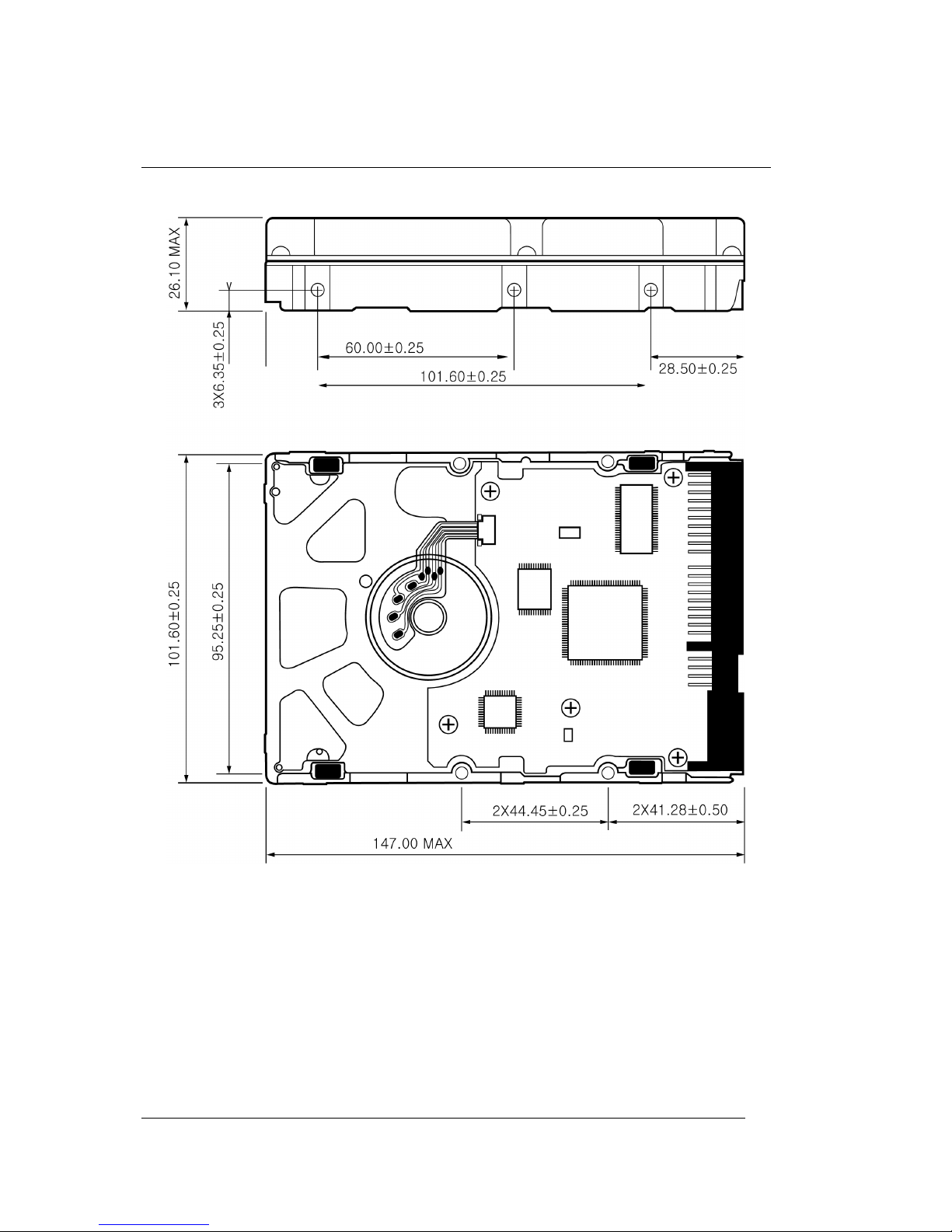
4.1 Space Requirements
Figure 4-1 shows the external dimensions of the drive.
Figure 4-1 Mechanical Dimension

INSTALLATION
SpinPoint P80 Product Manual Rev. 01 13
4.2 Unpacking Instructions
(1) Open the shipping container of the SpinPoint P80.
(2) Lift the packing assembly that contains the drive out of the shipping container.
(3) Remove the drive from the packing assembly. When you are ready to install the drive, remove it from
the ESD (Electro Static Discharge) protection bag. Take precautions to protect the drive from ESD
damage after re m o ving it from the bag.
CAUTION: During shipment and handling, the anti-static ESD protection bag
prevents electronic component damage due to electrostatic discharge. To avoid
accidental damage to the drive, do not use a sharp instrument to open the ESD
protection bag.
(4) Save the packing material for possible future use.
4.3 Mounting
Refer to your system manual for complete mounting details.
(1) Be sure that the system power is off.
(2) For mounting, use four 6-32 UNC screws.
CAUTION: To avoid stripping the mounting-hole threads, the maximum torque
applied to the screws must not exceed 8.0 Kg-cm (6.95 inch-pounds).
4.3.1 Orientation
Figure 4-2 shows the physical dimensions and mounting holes located on each side of the drive. The
mounting holes on SpinPoint P80 hard disk drives allow the drives to be mounted in any direction.
INSTALLATION
SpinPoint P80 Product Manual Rev. 01
14
Figure 4-2 Mounting Dimensions (in Millimeters)
INSTALLATION
SpinPoint P80 Product Manual Rev. 01 15
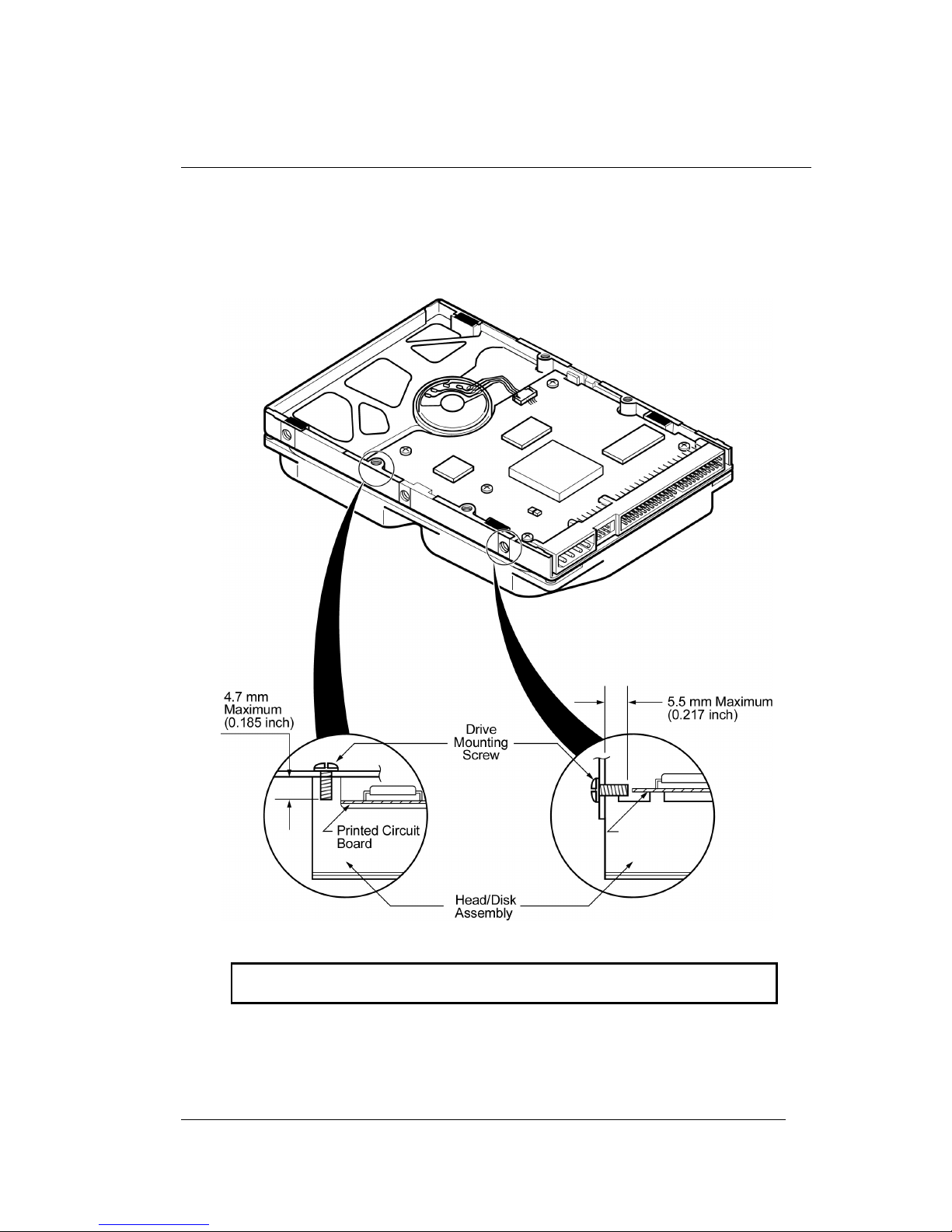
4.3.2 Clearance
The printed circuit board (PCB) is designed to be very close to the mounting holes. Do not exceed the
specified length fo r the mounting screw described in Figure 4-3. The specified screw length allows full use of
the mounting-hole threads, while avoiding damage or placing unwanted stress on the PCB.
Figure 4-3 Mounting-Screw Clearance
CAUTION: Using mounting screws that are longer than the maximum
lengths specified in Figure 4-3 voids the warranty of the drive.

INSTALLATION
SpinPoint P80 Product Manual Rev. 01
16
4.3.3 Ventilation
SpinPoint P80 hard disk drives are designed to operate without the need of a cooling fan, provided the
ambient air temperature does not exceed 55ºC. Any user-designed cabinet must provide adequate air
circulation to prevent exceeding the maximum temperature.
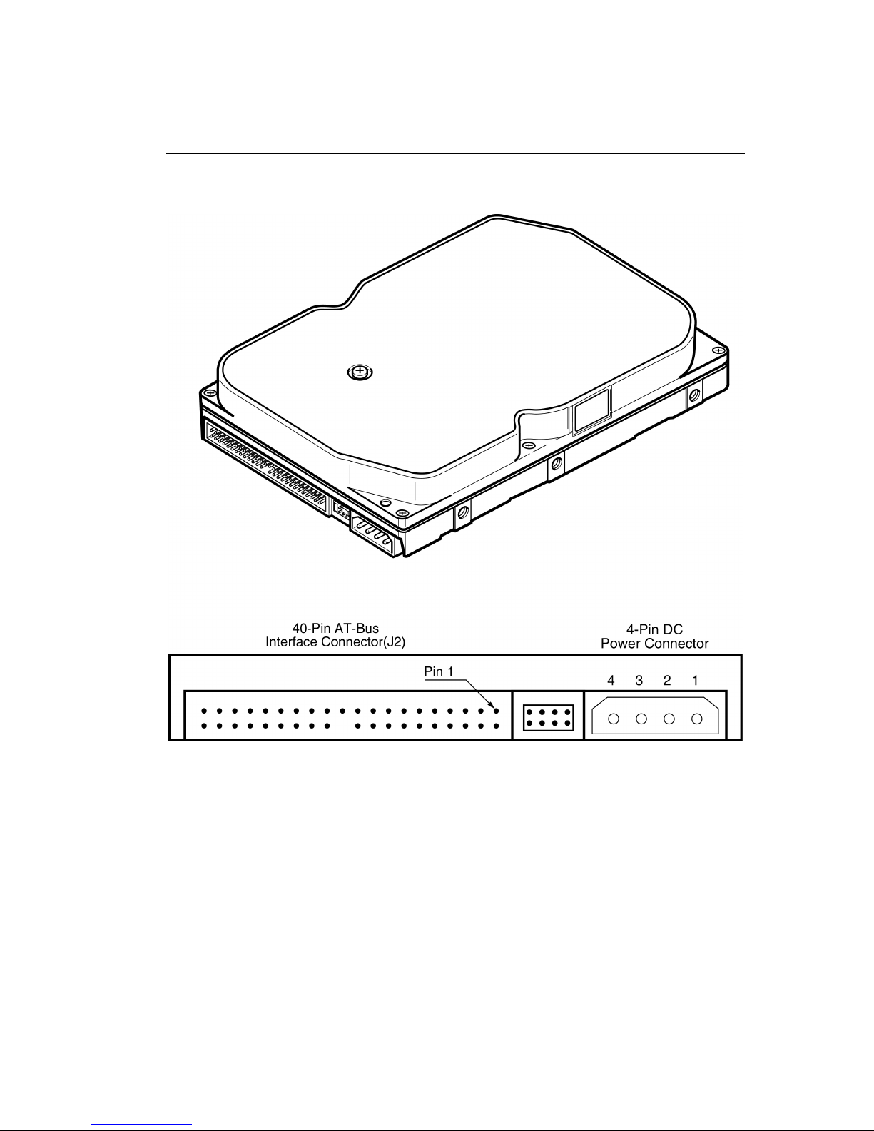
4.4 Cable Connectors
The Interface/Power connector consists of three portions; a DC power connector, a configuration jumper
block, and the standard 40 pin AT-Bus Interface connector.
4.4.1 DC Power Connector
The DC power connector is mounted on the back edge of the Printed Circuit Board (PCB)
(Figure 4-4). Table 4-1 lists the pin assignments.
Table 4-1 Power Connector Pin Assignment
Pin Number Power Line Designation
1 +12V DC
2 +12V Return (Ground)
3 +5V Return (Ground)
4 +5V DC
4.4.2 AT-Bus Interface Connector
The AT-Bus interface connector on the drive connects the drive to an adapter or an on-board AT a dapter in
the computer. JHST is a 40-pin Universal Header with two rows of 20 pins on 100-mil centers, as shown in
Figure 4-4.
To prevent the incorrect installation of the I/F cable, the connector has been keyed by the removal of Pin #20.
The connecting cable is a 40-conductor or a 80-conductor flat ribbon cable, and the maximum cable length is
0.46m (18 inches).
For pin assignments and si gnal d esc ri ptions, see Chapter 6, AT Interface and ATA Comman ds .
INSTALLATION
SpinPoint P80 Product Manual Rev. 01 17
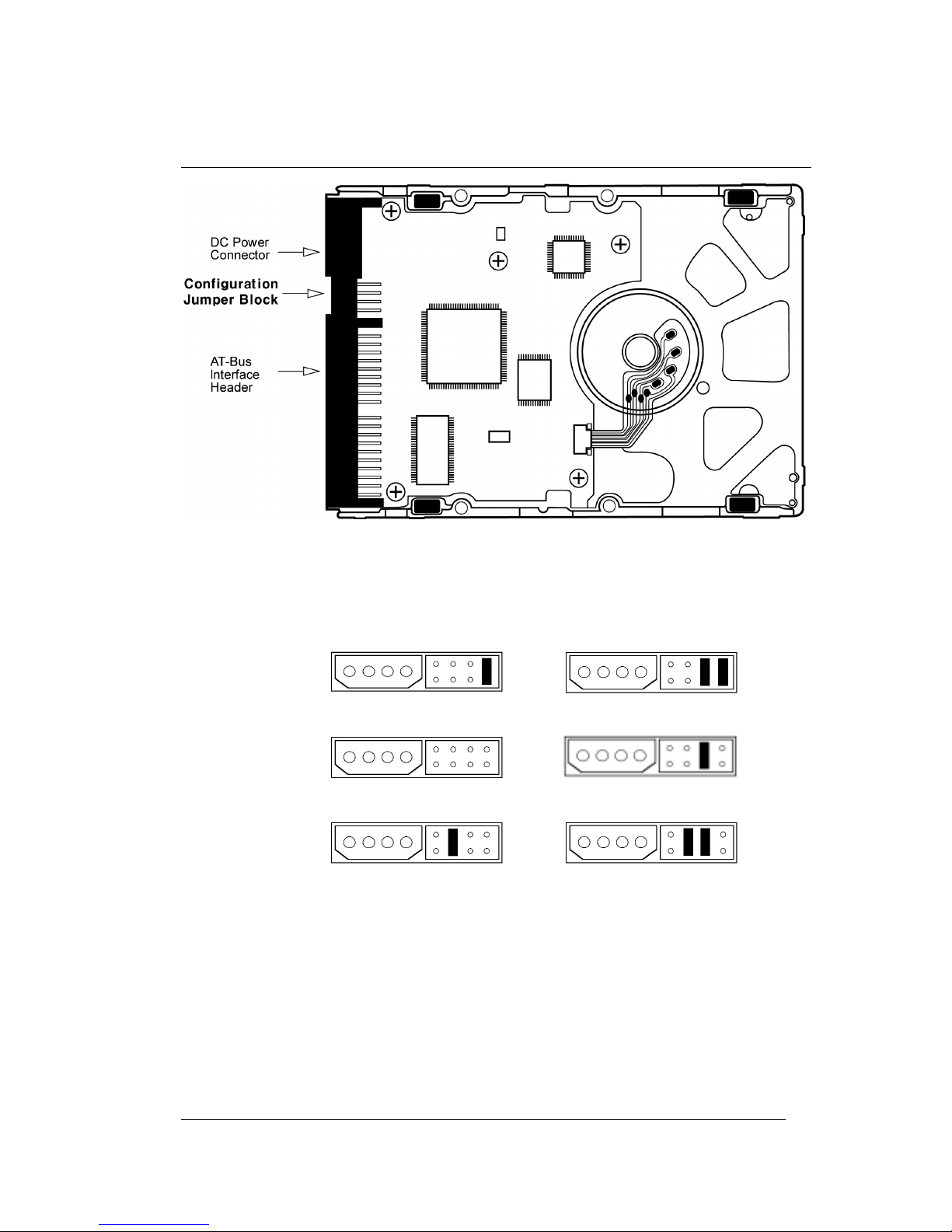
Figure 4-4 DC Power Connector, Configuration Jumper Block & AT-Bus Interface Connector (JHST)
INSTALLATION
SpinPoint P80 Product Manual Rev. 01
18
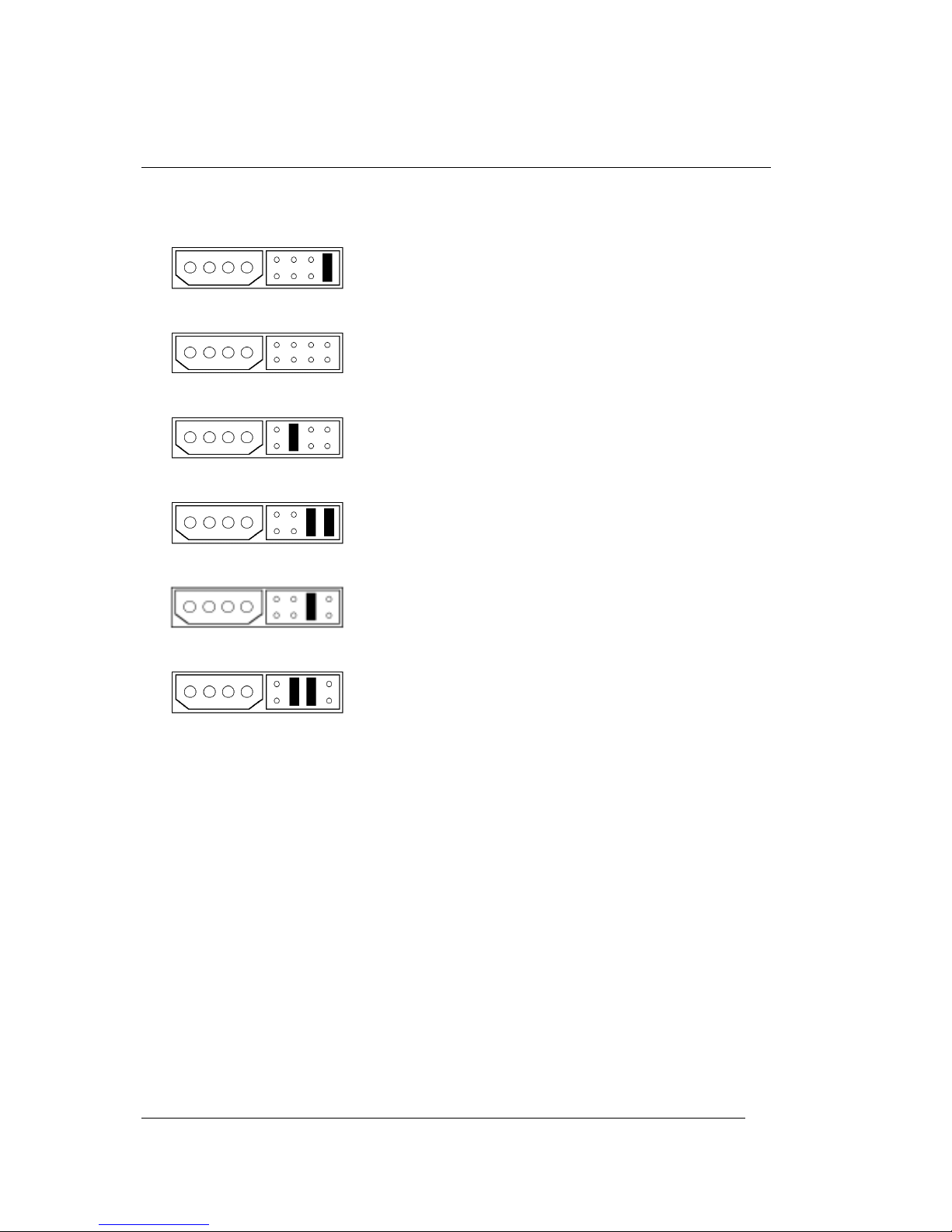
4.5 Jumper Block Configurations
Master Mode
This mode is selected as the fact or y default. It co nfi gures t he
drive as the Master.
Slave Mode
Select this mode to configure the drive as the Slave.
Cable Select Mode
Select this mode if the Cable Select feature of the AT Bus
Interface is to be used for Master / Slave selection.
Master Mode wit h 32GB Clip
Select this mode to limit the capacity of the drive to 32 gigabytes
and configure the drive as the Master, or to help install the drive
to access the full capacity of the drive as the Master in certain old
PC systems.
Slave Mode with 32GB Clip
Select this mode to limit the capacity of the drive to 32 gigabytes
and configure the drive as the Slave, or to help install the drive to
access the full capacity of the drive as the Slave in certain old PC
systems.
Cable Select Mode with 32GB Clip
Select this mode to limit the capacity of the drive to 32 GB and
use the Cable Select feature of the AT Bus Interface for Mast er /
Slave selection, or to help install the drive to access the full
capacity of the drive using Cable Select feature in certain old PC
systems.
NOTES:
• The 32GB Cli p may be required for the hard disk drive to b e recognized by system s that incorporate
specific older BIOS. For t he install ation instructions, refer to section “4.7.1 Drive Inst allation to Access
the Full Capacity Using 32GB Clip.”
•
The ATA standard allows for daisy-chaining up to two drives on the AT-Bus interface. When daisychaining two drives, specify one drive as the Master and the other as the Slave. Both drives could also be
set to Cable Select Mode if the host is using the Cable Select feature of the AT Bus Interface.
• SpinPoint P80 hard disk drives are shipped from the factory in Master Mode (Drive 0).
INSTALLATION
SpinPoint P80 Product Manual Rev. 01 19
Figure 4-5 Jumper Pin Locations on the Drive PCBA
Master
Master Mode with 32GB Clip
Slave
Slave Mode with 32GB Clip
Cable Select
Cable Select Mode with 32GB Clip
Figure 4-6 Options for Jumper Block Configuration
INSTALLATION
SpinPoint P80 Product Manual Rev. 01
20
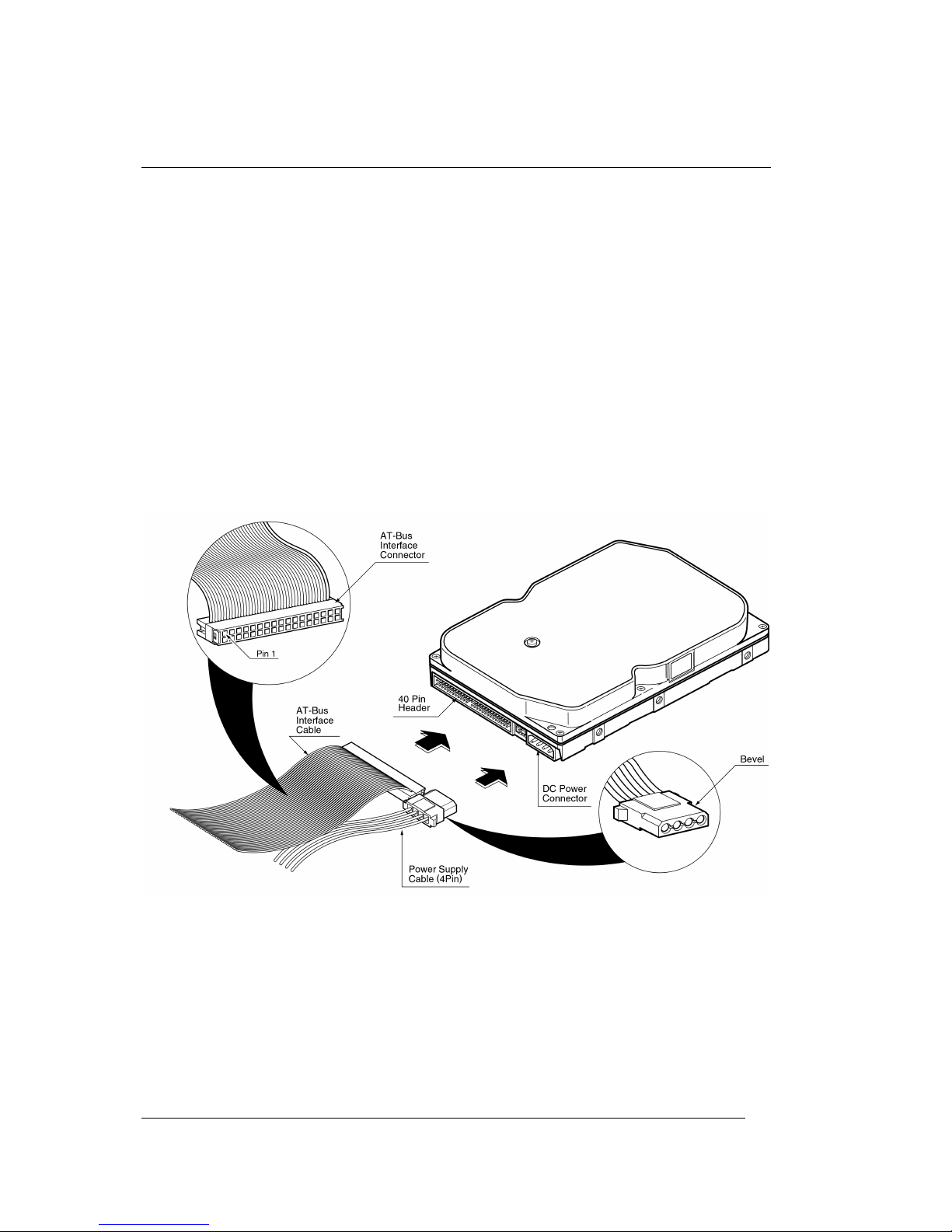
4.6 Drive Installation
The SpinPoint P80 hard disk drive can be installed in an AT-compatible sy stem in two ways:
• To install the drive with a motherboard that contains a 40-pin AT-bus connector, connect the drive to the
motherboard using a 40-conductor or a 80-c onductor ribbon cable. Ensure that pin 1 of the drive is
connected to pin 1 of the motherboard connector. For UDMA mode 2 or higher, use a 80-conductor
ribbon cable.
• To install the drive in a system without a 40-pin, AT-bus con nector on its motherboard, an AT-bus
adapter kit is required. The kit includes an adapter board and a ribbon cable to connect the board to the
drive.
Figure 4-7 indicates the cable and power cord connections required for proper drive installation.
Figure 4-7 DC Power Connector and AT-Bus Interface Cable Connections

INSTALLATION
SpinPoint P80 Product Manual Rev. 01 21
4.7 Sy stem Startup Proce dure
Once the SpinPoint P80 hard disk drive and along with the adapter board (if required) have been installed in
your system, the drive can now be partitioned and formatted for operation. To set up the drive correctly,
follow these instructions:
1. Power on the system.
2. Typically the system will detect a configuration change automatically. If so, then jump to step 6.
3. If installing SpinPoint SP0401N, SP0802N, SP1203N, & SP1604N model and the system hangs during
boot up,(or bios does not detect the drive), follow the instructions in section “4.7.1 Drive Installation to
Access the Full Capacity Using 32GB Clip”.
If system does not support 137GB consult Microsoft Corporation or the PC maker for upgrading bios
and/or Microsoft Corporation service pack
4. If the system does not hang but doe s not automatically detect the drive either during reboot, r un the setup
program of the system. Setup pr ogram is usually on a diagnostics or utility disk, or in the system BIOS.
Refer to the manual of your system for this operation. Once you ge t into setup prog ram then follow step
5. Perform one of the following steps that applies to your system:
I. Select “Auto Detect” if it is supported.
II. When using “User Defined” type , enter the appropriate parameters for the installed drive,
according to
Table 4-2
.
III. When using “Pre-Defined” type, select any drive type that does not exceed the maximum capacity
of the drive. Table 4-2 shoes the logical parameters that provide the maximum capacity of
SpinPoint P80 family drives.
6. If the system recognizes the drive but experiences problems on properly handling the full capacity of the
drive, run Disk Manager utility program provided by Samsung and follow the instructions. The Disk
Manager utility program is available from Samsung on a floppy diskette, or downloadable from the
Samsung website at www.samsunghdd.com
. If, after all these steps are succes s fu lly completed, your
system will not boot up, then contact technical support.
Table 4-2 Logical Drive Parameters
PARAMETER SP0401N SP0802N SP1203N SP1604N
Logical Cylinders
77,622
155,127
232,632
310,137
Logical Heads
16 16 16 16
Logical Sectors
63 63 63 63
T
otal Number of Logical Sectors
78,242,976 156,368,016 234,493,056 312,618,096
Capacity
40.06 GB 80.06 GB 120.06 GB 160.06 GB
NOTES:
• The total numbers of sectors is calculated by (Cylinders x Heads x Sectors) of the selected drive

INSTALLATION
SpinPoint P80 Product Manual Rev. 01
22
type.
•
Maximum number of logical cylinders in CHS mode is 16,383.
• Systems that incorporate more than an 8.4GB per storage device must access the drive in LBA
addressing mode.
•
Windows 95 or 98 that use FAT16 file system will limit the drive’s logical partition at 2.1GB per
logical drive. Windows95 OSR2 or later allow for the FAT32 file system which provides access to
greater than 2GBof logical capacity.
•
A low-level format is not required, as this was done at the factory before shipment.
4.7.1 Drive Installation to Access the Full Capaci ty Using 32GB Clip
A system hang condition is identified when the installation of a hard disk drive large r than 32G B is a ttempted
into a PC system that incorporates specific older BIOS’. This issue is caused by the older BIOS’ inability to
support the full capacity of the hard disk drive, not by the SpinPoint P80 hard disk drive.
One solution to this issue, is to contact the system or motherboard manufacturer and upgrade the BIOS (to
enable the system to access the full capacity of the hard disk drive).
As an alternative solution, the drive can be installed by using a 32GB clip jumper on the SpinPoint P80 hard
disk drive, along with the Disk Manager utility program. To set up the drive using 32GB clip, follow the
instructions provided below:
1. Install a 32 GB clip jumper (see section 4.5).
2. Boot up the system, enter SYSTEM SETUP, change the settings for the drive to “Auto”, and exit
SYSTEM SETUP.
NOTE: At this point in the installation, the drive capacity is limited to 32GB. No further steps are
needed if the drive is intended to be used as 32 gigabytes.
3. To access the full capacity, reboot the system with the Disk Manager diskette. Disk Manager will install
Dynamic Drive Overlay on the drive. The Dynamic Drive Overlay will take control of the drive from
the BIOS each time the system is booted, and enable access to the entire capacity of the drive.
4. Select “Easy Disk Installation”
5. Select drive to be installed (master or slave)
6. Select the operating system (Win95 OSR2, 98, 98SE, ME, NT, 2000,XP)
7. Follow the instruction to format drive
NOTE;
Microsoft identified a 32GB capacity limitation issue with the Windows 95 operating system. The solutions
provided above do not overcome the capacity limitation of the Windows 95 operating system. Microsoft
recommends that Windows 95 customers who want to use media larger than 32GB, upgrade to Microsoft
Windows 98 or Microsoft Windows NT. For more information, please check Microsoft Knowledgebase.
4.7.2 Drive Installation to Access the Over than 128GB (or 137GB)
Drive access more than 128GB or 137GB capacity for Palo 160GB drive
Some motherboards may have updated BIOS available that enables 48-bit support. At this
time however, 48-bit BIOS support is only needed if using Windows* Me, Windows 98 SE, or
Windows 98. Additional information on why the BIOS may limit FDISK when partitioning hard
drives can be found at this Microsoft* Knowledge Base article
†. While 48-bit LBA BIOS
support is not needed for Windows XP or Windows 2000, it may add certain 48-bit BIOS
functionality. This is limited to items such as the BIOS setup menu, Power-On Self Test (POST)
screen, and operation in a MS-DOS*-based environment.
 Loading...