

Samsung SN-S082D, TS-K632D Service Manual
The exterior design and some parts of the product may be changed without prior notification.
Service
Manual
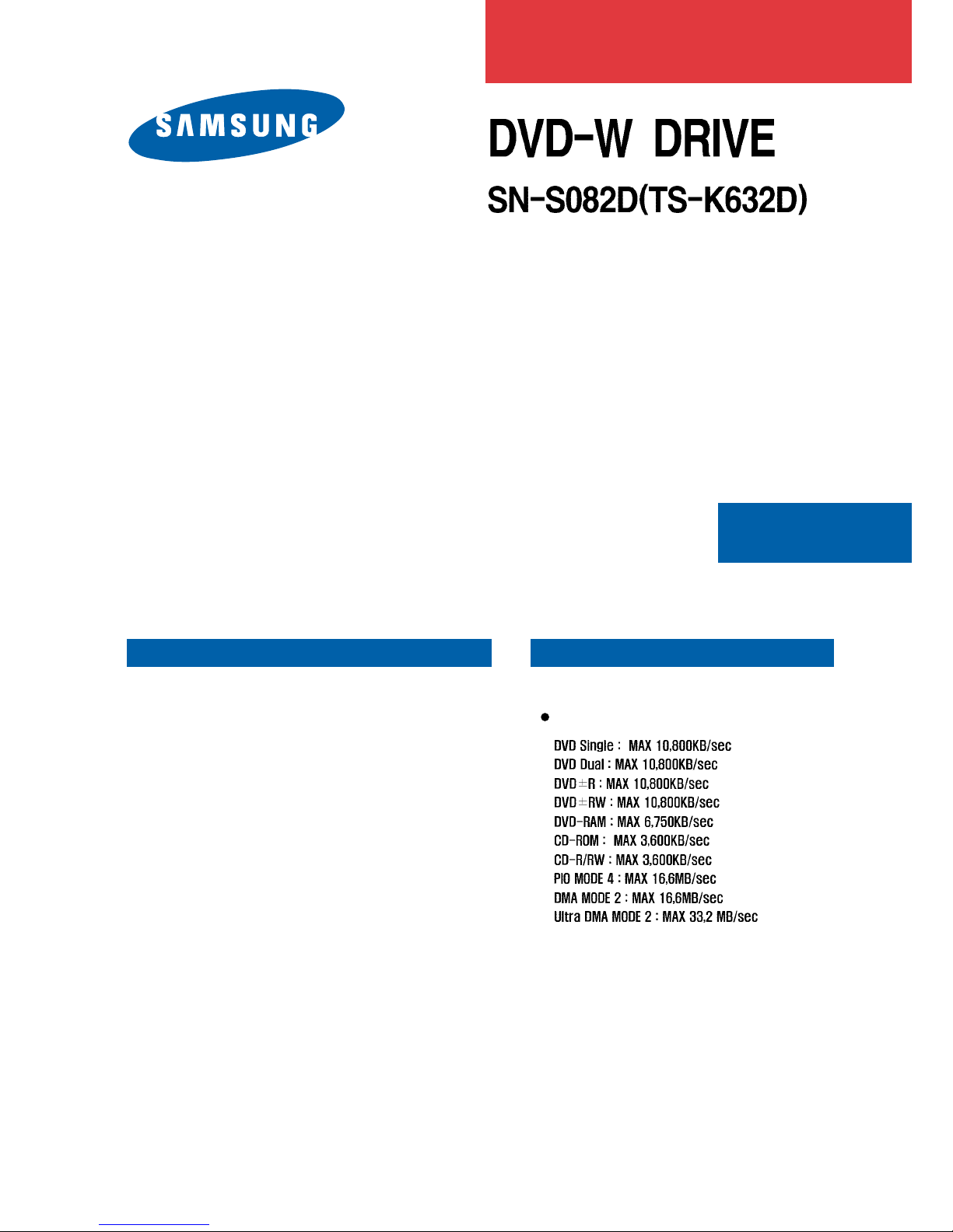
DVD-W SLIM
DVD-W SLIM
Product Features
Product Features
READ

Contents
Contents
Chapter 1 Safety Precautions
Chapter 2 General Specifications and
Features
Chapter 3 Functional Description and
Installation
Chapter 4 Disassembly and Assembly
Chapter 5 Troubleshooting
Chapter 6 Block Diagram
Chapter 7 Schematic Drawings

1
1-1. Safety Precautions for Repairs
1. Safety Precautions
1) Since the equipment uses laser diode, ensure
that eyes and parts of the body do not come
near the laser diode while performing repair
service.
2) Do not disassemble pickup to repair. If the laser
diode is faulty, then replace the complete pickup
assembly.
3) Perform repair services away from electrical
equipments such as TV to avoid interference
from these equipments.
4) Ensure to unplug the power cord from the unit
before replacing any parts.
5) Ensure to insert the disc properly into the unit
before use.
6) Since this equipment cannot be used as a
standalone unit, it must be installed in a PC
(586 or higher) with appropriate device driver from
the floppy disk to verify proper operation.
7) This equipment has many parts with properties
related to safety. These parts are specifically
noted in the parts list and schematic drawings.
Ensure to replace these parts with new parts
that have the same specifications.
- Since the laser diode in the optical pickup
bundle can be easily damaged by the static
electricity in human body or clothing, use
the following grounding guidelines when
handling the bundle.
Wear a wrist strap with one end properly
grounded. The wrist strap discharges the static
electricity in human body.
Work on a conductive material such as copper
plate that is properly grounded.
Since the static electricity stored in clothing is
not easily discharged, ensure that clothing does
not make a contact with the pickup bundle.
1-2. Safety Precautions for Installations
A certain semiconductor components are highly
susceptible to damages caused by electrostatic
discharge (ESD).
Semiconductors components such integrated circuits,
field effect transistors, and other semiconductor
devices are examples of devices that are highly
sensitive to ESD.
Use the following guidelines to reduce the damages
caused by the ESD.
1) Before handling any semiconductor components
or parts that contains semiconductors,
immediately discharge all static electricity in the
body by making a contact with a grounded
metallic object. A commercially available wrist strap
may also be used.
The static electricity must be discharged to avoid
potential impact on the voltage during testing.
2) After removing ESD-sensitive components or
parts, place the items on a conductive surface
such as on a piece of aluminium to prevent
accumulation of charges and exposure to ESD.
3) Use properly grounded soldering iron to solder
or to de-solder ESD-sensitive components.
4) Only use anti-static soldering iron to de-solder
ESD-sensitive components.
Use of soldering irons not classified as “anti -static”
has enough electrostatic charges to cause damages
to the components.
5) Do not use chemical sprays such as Freon.
These chemicals have enough electrostatic
charges to cause damages to the ESD-sensitive
components.
6) Do not remove replacement parts from the
anti-static packaging until they are ready for
installation. [Most of the replacement parts are
packaged in conductive foam, aluminium, or
other conductive materials with all the leads
shorted together.]
7) Before removing the anti-static packing
materials for the new parts, make a contact with
the chassis or protective material for the circuits
to discharge the static charges.
8) Minimize body movement when handling
unprotected ESD-sensitive parts and
components. (The movement of body causes
build up of electrostatic charges from friction
between layers of clothing, and between the
shoes and the carpet which may cause damage
to the components.)
Caution: Ensure that the power does not get transferred to
the chassis or to the circuitry, and that all general
safety guidelines are followed.
2
1-3. Static Electricity, PL, and Voltage Safety Precautions
1) Read all safety and operational manuals before
operating the product.
2) Keep the safety and operational manuals for
future reference.
3) Follow all precautions and operational
instructions shown inside or on the outside of
the product.
4) Follow all operational and maintenance
precautions.
5) Unplug the power cord from the socket before
cleaning operation. Do not use liquid or aerosol
type of cleaners to clean the exterior cabinet.
Use a dry cloth only to clean the dust off the
cabinet.
6) Do not use any attachments not recommended
by the manufacturer. This may be unsafe and may
damage the product.
7) Do not use the product near water such as
bathtubs, washbasins, washing machines,
swimming pools, or lakes.
8) Never place the product on the bed, sofa,
radiator, or near any heat source.
9) Power: Only use the type described on the label.
Contact the dealer if the power type cannot
be identified. To operate the product using
batteries or other sources of power,
consult the operating manual.
10)Lightening: Unplug the power during lightening
and during a long period when the
product is not being used.
11) Electrical Overload: Do not plug excessive number of
power cords into the outlet
or extension outlet to prevent fire
hazard and electrical shock.
12) Never put any object or liquid in the product.
It may cause fire or electrical shock due to a
potential contact with the power supply and/or
short-circuit.
13) Replacement Parts: The service technician
must use a replacement part with
the same exact specification.
Use of replacement part with
incorrect specification may
result in fire, electrical shock,
and other safety hazards.
14) Safety Inspection: Always perform a safety
inspection after a service
and/or repairs.
Important Safety Precaution:
The product contains special components important for
safety.
These components are identified with in the schematic
drawings.
These components must be replaced with components with
the exact same specification to prevent electrical shock, fire,
and other hazards.
Do not modify any part of the original product design without
manufacturer
s permission.
Warning: A death or a serious injury may result if the
instructions are not followed properly.
Caution: Property damage may result if the instructions
are not followed properly.
Description of Warning / Caution

3
2. General Specifications and Features
2-1. General Specifications
2-2. Features
DC +5V, 1.5A
- Drive Type:
- Power Consumption:
Internal
- Interface: S-ATA
- Data Transfer Rate:
CD
DVD
Write (CD-R)
1,200KB/sec ( 8X), 2,400KB/sec (16X)
3,600KB/sec (24X), 4,800KB/sec (32X)
6,000KB/sec (40X), 7,200KB.sec (48X)
Write (CD- RW)
600KB/sec ( 4X), 1,500KB/sec (10X)
2,400KB/sec (16X), 3,600KB/sec (24X)
4,800KB/sec (32X),
Read (CD- ROM)
6,000KB/sec (Maximum: 40X)
7,200KB/sec (Maximum: 48X)
Read (DVD±R, DVD±RW) 10,800KB/sec(8X), 16,200KB/sec(12X)
Write
(DVD+R) 21,600 KB/sec(16X)
Write
(DVD-R) 21,600 KB/sec(16X)
Write
(DVD+RW,-RW) 10.800KB/sec(8X), 8,100KB/sec(6X)
Write
(DVD+R DUAL LAYER) 10,800KB/sec(8X)
Write
(DVD+R DUAL LAYER) 5,400KB/sec(4X)
Write (DVD-RAM )6,750MB/sec (FAT32)
- ACCESS TIME
- (CD-ROM) 1/3 Stroke: < 130ms
Full Stroke: <160ms
- (DVD-ROM) 1/3 Stroke: < 130ms
Full Stroke: <160ms
- Buffer Size: 2MB
- Error Rate: Mode 1:10-12
Mode 2: < 10-9
- Frequency Response: 20Hz~20KHz (Line out)
- Signal to Noise Ratio: 70dB (1KHz, Line out)
- Distortion: < 0.15% (1KHz)
- Channel Separation: Line out: 65dB (1KHz)
- Laser Type: Semiconductor Laser
- Audio Output: Line out : 0.7Vrms¡¾10% 47Kohm
- Dimensions:
128(W) X 12.7(H) X 127(D)
- Weight:
170g

3. Functional Description and Installation
4
3-1. Hardware Functional Description
Read
CD-ROM: CAV 24X Max.
CD-R: CAV 24X Max.
CD-RW: CAV 24X Max.
5
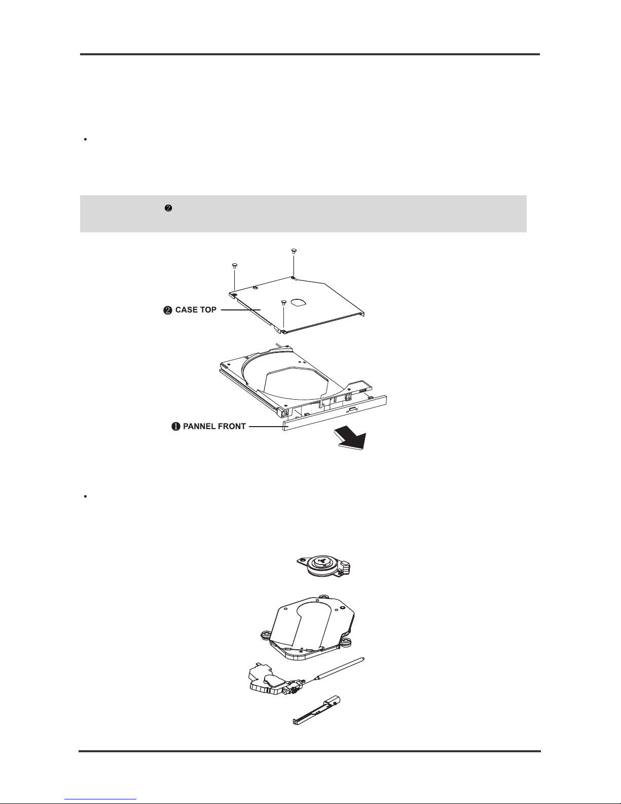
4-1. Disassembly
CASE-TOP and ASSY PANEL FRONT Disassembly
4-1-1. Exterior Components and PCB Disassembly
(a) Unscrew 3 Screws in the back by ejecting SET and pulling it forward.
(b) Detach CASE TOP by pushing back and lifting up.
(c) Detach COVER-DECK.
Note: If the tray does not open, then force the tray open manually by pushing the pin Clip 3
into the emergency hole on the unit.
ASSY-FEED ING Disassembly
(a) Detach FPC-SUB from MONITOR-SPINDLE, and FPC-PU,
FPC-MONITOR SPINDLE from MAIN-PCB.
(b) Detach ASSY-FEEDING from ASSY-TRAY.
4. Disassembly and Assembly

6
ASSY-SOLENOID Disassembly
(a) Unscrew 2 SCREWs in the bottom of ASSY TRAY.
(b) Detach GUIDE GROUND.
(c) Detach ASSY-SOLENOID from ASSY TRAY.
ASSY PCB MAIN Disassembly
(a) Unscrew 2 SCREWs in ASSY PCB MAIN.
(b) Detach FPC MAIN by turning over ASSY PCB MAIN.
(c) Detach ASSY PCB MAIN from ASSY TRAY.
 Loading...