How it Works
Log In / Sign Up
Buy Points
How it Works
FAQ
Contact Us
Questions and Suggestions
Users
Samsung
Loading...
S
SNB-1000
2
SNB-1000-N
2
SNB-1001
4
SNB-2000
SNB-2000-N
2
SNB-2000P
2
SNB-2312
2
SNB-2312 KIT
SNB-3000
2
SNB-3000N
2
SNB-3000P
2
SNB-3002
4
SNB-5000
8
SNB-5000N
SNB-5000P
SNB-5001
4
SNB-5003
SNB-5004
3
SNB-5004N
SNB-5004P
SNB-600
SNB-6003
4
SNB-6004
7
SNB-6005
2
SNB-6010
5
SNB-6010B
2
SNB-6011
2
SNB-6011B
2
SNB-6011B-15
SNB-7000
5
SNB-7000N
2
SNB-7000P
2
SNB-7001
3
SNB-7001N
SNB-7002
3
SNB-7004
4
SNB-8000
2
SNB-9000
2
SNB-B-6024
2
SNB-B-6024B
SNB-B-6025B
SNB-J-6010B
2
SNC-1300
SNC-35E
SNC-4241BE
SNC-550
SNC-550 iPOLiS
SNC-570
SNC-570-N
2
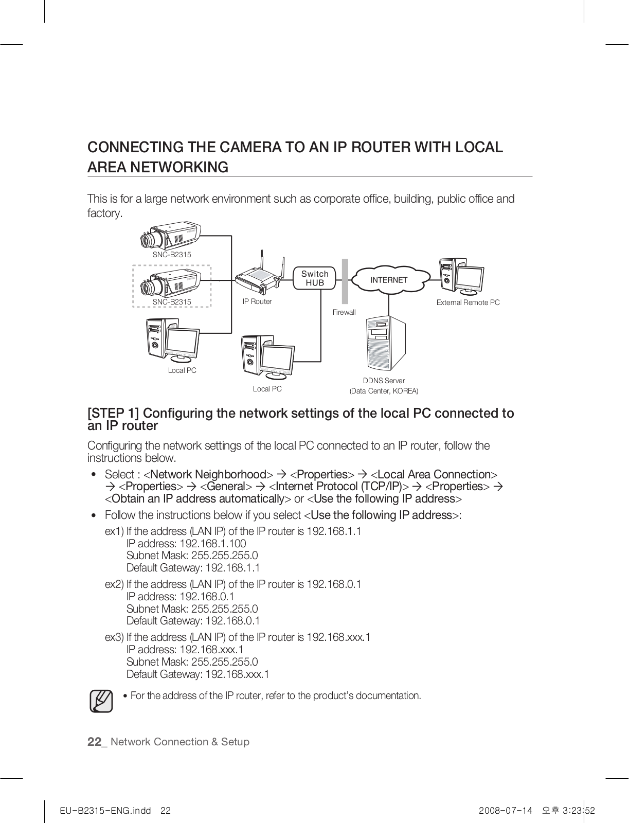
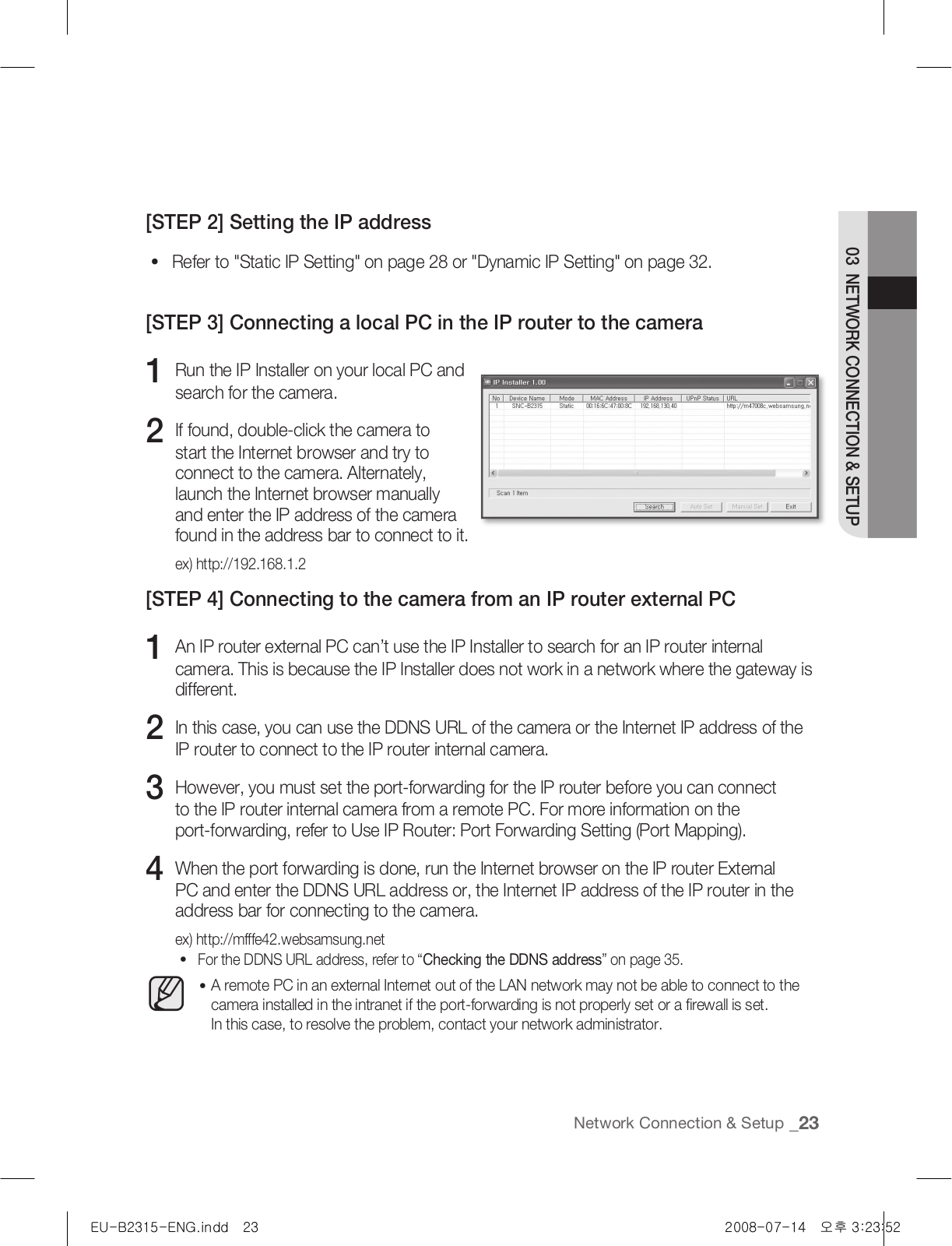
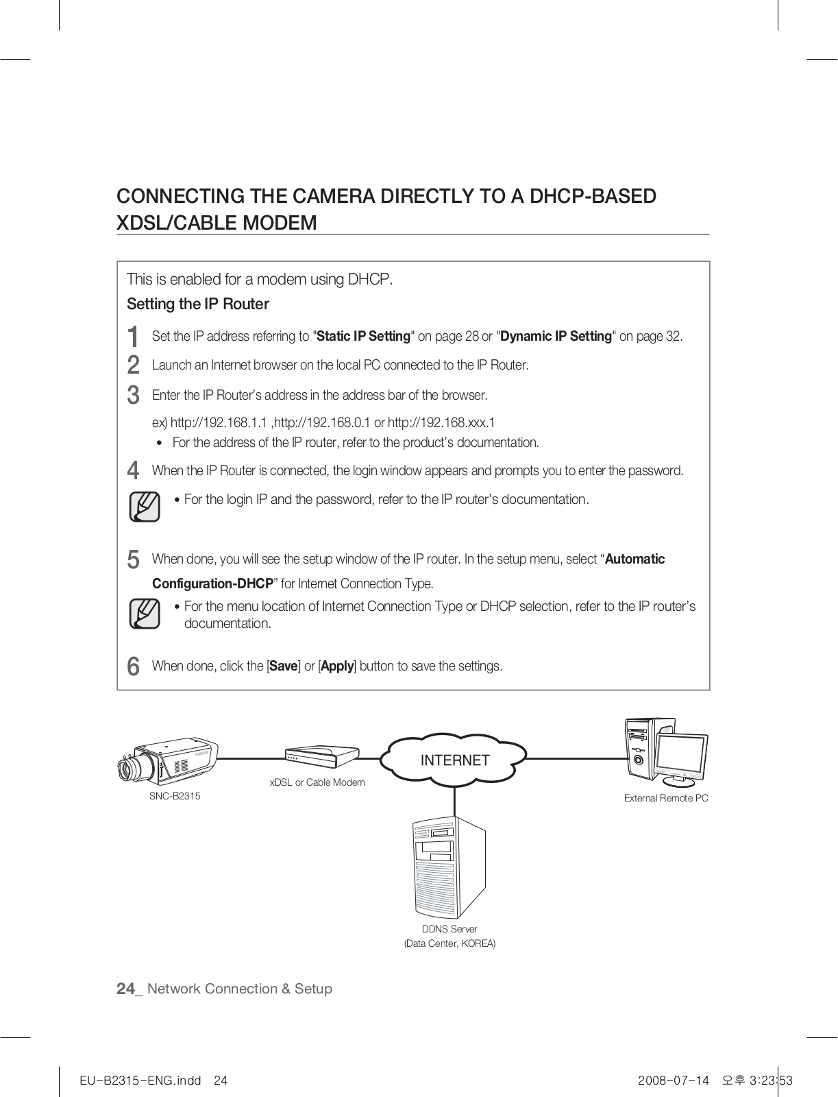
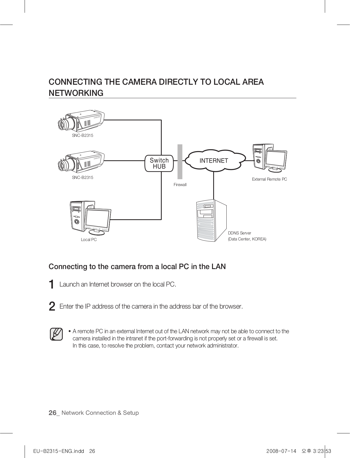
SNC-B2315
3
SNC-B2315P
SNC-B2331
2
SNC-B2331-FRA-QG
SNC-B2331P
2
SNC-B2335
3
SNC-B2335P
2
SNC-B5368
4
SNC-B5368-N
SNC-B5368P
2
SNC-B5395
2
SNC-B5395P
SNC-B5399
2
SNC-B5399-N
2
SNC-B5399(P)
3
SNC-C6225
3
SNC-C7225
4
SNC-C7225 Mini SmartDome
SNC-C7478
6
SNC-C7478C
2
SNC-C7478CP
SNC-C7478P
SNC-L200
3
SNC-L200N
SNC-L200P
3
SNCL200W
SNC-L200WP
2
SNC-M300
3
SND
SND-1010
SND-1011
2
SND-1080
4
SND-1080N
2
SND-3080
2
SND-3080C
2
SND-3080CF
2
SND-3080F(P)
SND-3080P
2
SND-3082
3
SND-3082F
4
SND-460V
SND-460VN
SND-460VP
SND-5010
3
SND-5011
4
SND-5011N
SND-5011P
SND-5061
4
SND-5080
9
SND-5080F
10
SND-5080N
Loading...
Loading...
Nothing found
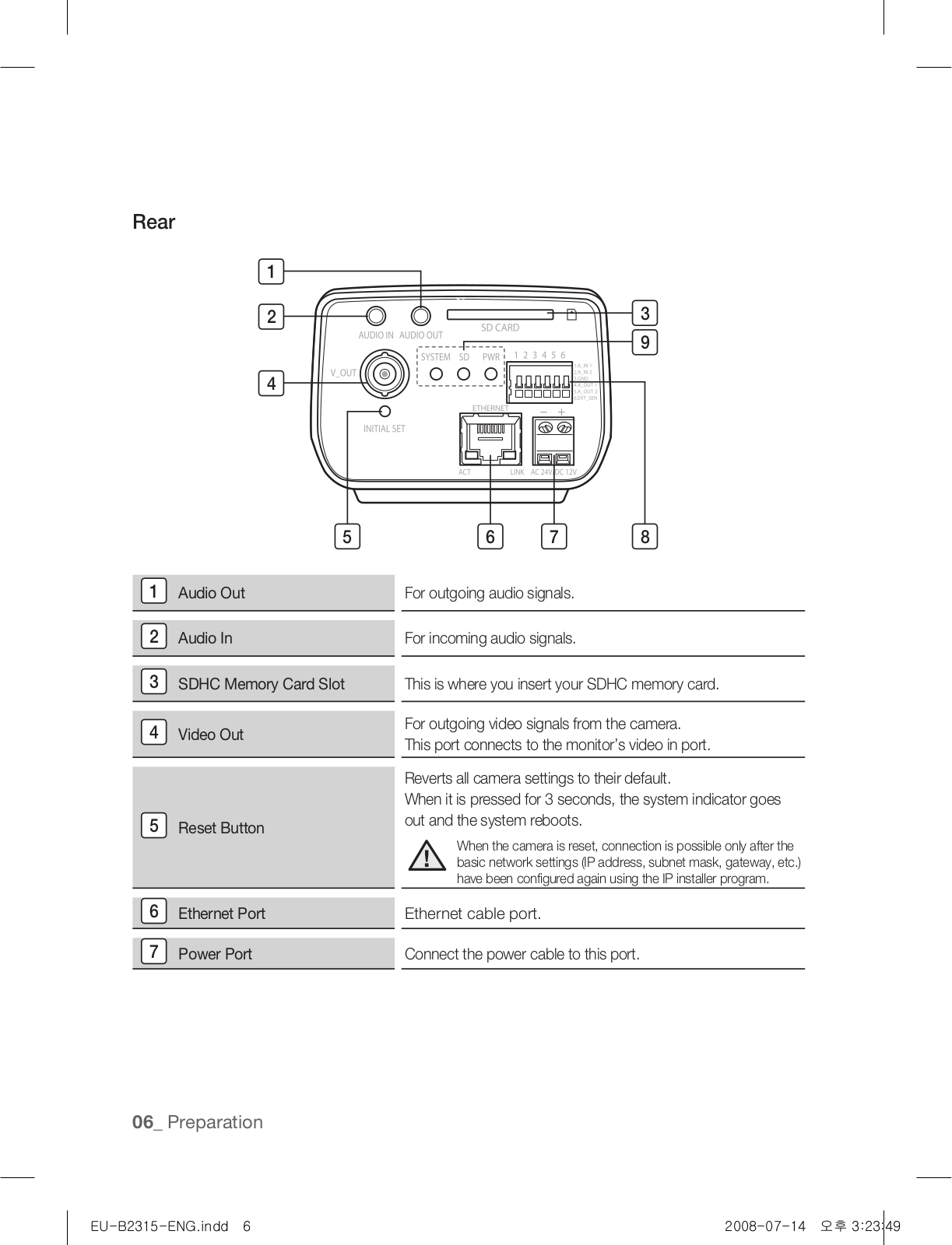
SNC-B2315P
User Manual
280 pgs
28.39 Mb
0
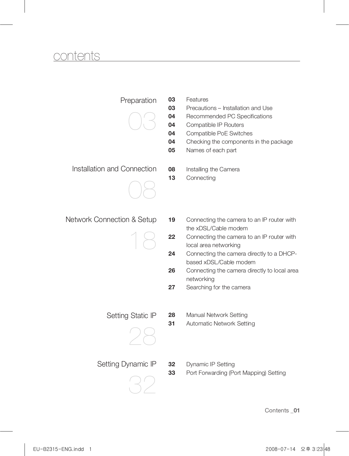
Table of contents
Loading...
Samsung SNC-B2315P User Manual
...
Samsung User Manual
Download
Specifications and Main Features
Frequently Asked Questions
User Manual
Download
Loading...
+
250
hidden pages
Unhide
You need points to download manuals.
1 point = 1 manual.
You can buy points or you can get point for every manual you upload.
Buy points
Upload your manuals
 Loading...