

Samsung SNK-D85121BF, SNR-D5401, SNC-4241BE User Manual

SNK-D85121BF
NETWORK VIDEO RECORDER
User Manual

2_ Overview of NVR
Overview of NVR
CONTENTS
OVERVIEW OF NVR
2
2 Contents
3 Safety Instruction
GET CLOSE TO NVR
4
4 Front Panel
5 Back Panel
6 Remote Controller
7 Install Hard Drive
8 Connect external equipment
8 Connect Camera
9 Connect NVR
9 How to assemble the waterproof RJ-45 coupler
11 Cable Protection
11 Installing the camera
NVR BOOT UP
12
12 System Initialization
12 Startup Wizard
15 Main Interface
NVR MENU
16
16 Popup Menu
17 Main Menu Guide
18 Main Menu
35 Menu Lock
36 Split Mode
36 Stream Switch
36 View Image Quality
36 Record Search
36 Start Sequence
WEB APPLICATION MANAGER
37
37 Download and Installation of Plugin
40 Web Application Manager Login
40 Live Interface
MOBILE APP
51
51 Android Phones/Tablets
52 iPhone/iPad
APPENDIX
53
53 Troubleshooting
55 Specifications
58 Dimension
SAFETY INSTRUCTION
Please carefully read the following safety instruction so as to avoid personal injuries and prevent the equipment and other connection
devices from being damaged.
1.
Please use the power supply enclosed or specified by the manufacturer.
Never operate the equipment by using unspecified power supply.
2.
Never push objects of any kind through openings of NVR so as to avoid electric shock or other accidents.
3.
Do not put the equipment in a dusty location.
4.
Do not place the equipment under the rain or humid environment like the basement.
If the equipment is accidentally in contact with water, please unplug the power cable and immediately contact technical support.
5.
Keep the surface of the equipment clean and dry.
Use a soft damp cloth to clean the outer case of the NVR. (Do not use liquid aerosol cleaners.)
6.
Do not operate if any problems are found.
If there is a strange smell or sound from the NVR, unplug the power cable and contact technical support.
7.
Do not try to remove the NVR cover to avoid electric shock.
8.
Handle with care.
If NVR does not work properly, please contact technical support for repair or replacement.
9.
Install and place the equipment in a well ventilated area. The NVR system includes a HDD, which produces large amount of heat
during operation. As a result, do not block the ventilation vents (on the top, bottom, sides and the back of the NVR).
10.
Do not install near any heat sources such as radiator, stove, and other machinery or devices (including speakers) that produce
large amount of heat.
11.
If the provided plug does not fit your outlet, please technical support for assistance.
12.
Protect the power cord from being walked on or pinched particularly at the plug level and each ends of the cord.
13.
Only use attachments/accessories specified by the manufacturer.
14.
Only use the cart, stand, tripod, bracket, or table specified by the manufacturer, or sold with the system.
When a cart is used, use caution when moving the cart and the device to avoid injury from tip-over.
15.
Unplug the device during lightning storms or when unused for long periods of time.
16.
Refer all servicing to qualified service personnel. Servicing is required when the device has been damaged in any way, such as
power-supply cord or plug is broken, liquid has been spilled or objects have fallen onto the device, exposed to rain or moisture,
does not operate normally, or has been dropped.
Standards Approvals
J
`
Any changes or modifications in construction of this device which are not expressly approved by the party responsible for compliance could void
the user's authority to operate the equipment.
M
`
This device complies with part 15 of the FCC Rules. Operation is subject to the following two conditions: (1) This device may not cause harmful
interference, and (2) this device must accept any interference received, including interference that may cause undesired operation.
`
This equipment has been tested and found to comply with the limits for a Class A digital device, pursuant to part 15 of the FCC Rules. These limits
are designed to provide reasonable protection against harmful interference when the equipment is operated in a commercial environment.
This equipment generates, uses, and can radiate radio frequency energy and, if not installed and used in accordance with the instruction manual,
may cause harmful interference to radio communications. Operation of this equipment in a residential area is likely to cause harmful interference
in which case the user will be required to correct the interference at his own expense.
Caution
•
Connect the power cord into a grounded outlet.
•
The Mains plug is used as a disconnect device and shall stay readily operable at any time.
•
Batteries shall not be exposed to excessive heat such as sunshine, fire or the like.
•
Risk of Explosion if Battery is replaced by an Incorrect Type. Dispose of Used Batteries According to the Instructions.
English _3
● OVERVIEW OF NVR
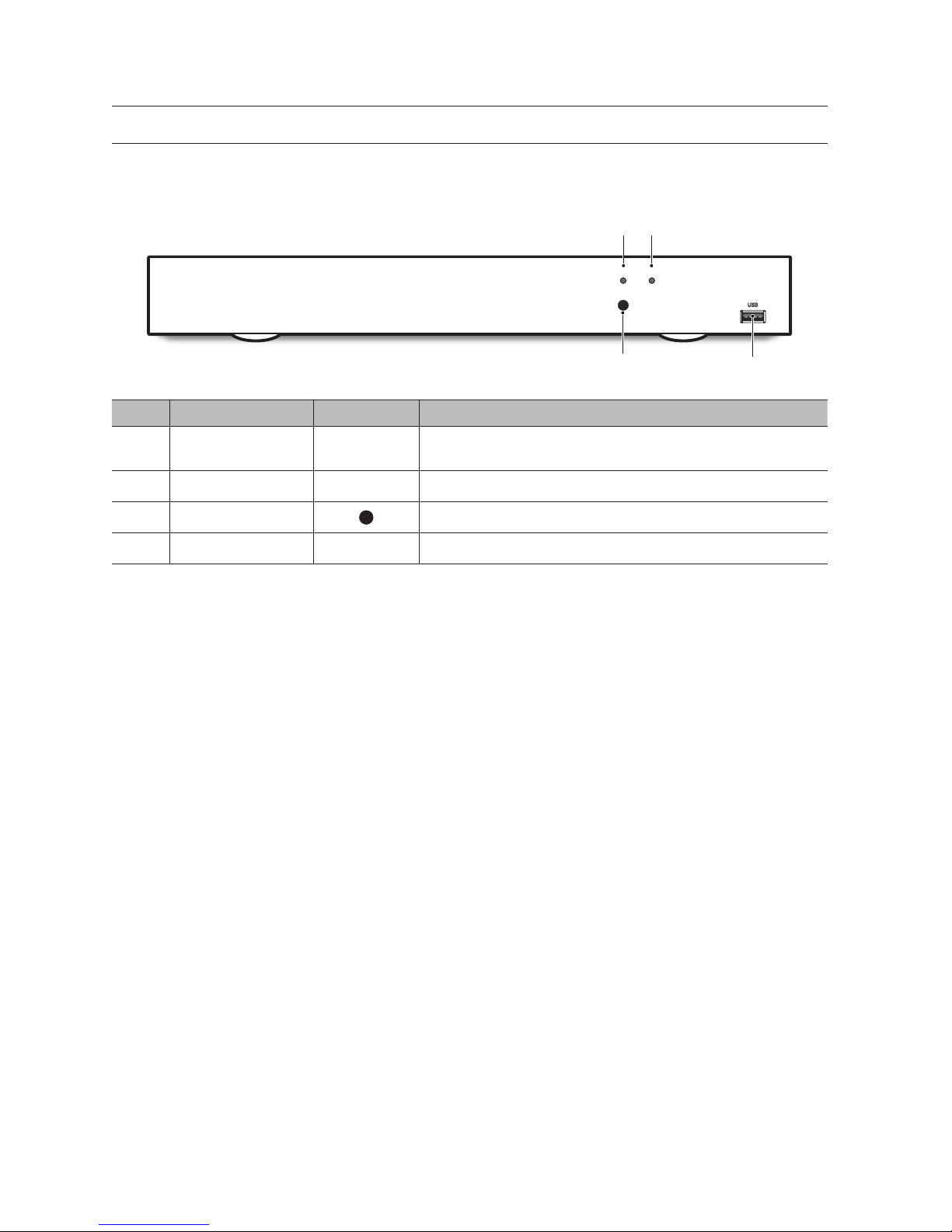
FRONT PANEL
NVR is the abbreviation of Network Video Recorder.
SNR-D5401
SN Key or LED Identification Functions
a
Power indicator lamp PWR
When the indicator lamp turns on in green color, it means that the NVR is powered
normally.
b
Hard drive indicator lamp HDD If the “Red” indicator flashes, the hard drive is being read or written to.
c
IR Signal Reception Port For reception of IR remote control signal.
d
USB USB USB Port
4_ Get Close to NVR
Get Close to NVR
DV25
SRN-475S
NETWORK VIDEO RECORDER
PWR HDD
a
b
c
d
BACK PANEL
SNR-D5401
SN Physical Interface Connection Instructions
a
e-SATA Connect to a e-SATA HDD
b
VGA Output Connect VGA display device, such as PC monitor.
c
AUDIO OUT No Function
d
LINE IN No Function
e
Power Switch Power the NVR on/off
f
Power Port Connect to power cable provided along with the device.
g
USB USB Port
h
HDMI Port Connect to monitor
i
WAN Port Router network I/O port/for connection to network camera
j
LAN Port LAN: network port, PoE compliant, and capable of supplying power to camera.
English _5
● GET CLOSE TO NVR
AC 100
240~IN
VGA
LINEIN AUDIO OUT
WAN
HDMI
LAN1
LAN2
LAN3
LAN4
LAN5
LAN6
LAN7
LAN8
LAN9
LAN10
LAN11
LAN12
LAN13
LAN14
LAN15
LAN16
CAUTION
RISK OF ELECTRI SHOCK
DO NOT OPEN
CAUTION : TO REDUCE THE RISK OF ELECTRICAL SHOCK
DO NOT OPEN COVERS. NO USER SERVICEABLE
PARTS INSIDE. REFER SERVICING TO QUALIFIED
SERVICE PERSONNEL.
WARNING : TO PREVENT FIRE OR SHOCK HAZARD. DO NOT
EXPOSE UNITS NOT SPECIFICALLY DESIGNED
FOR OUTDOOR USE TO RAIN OR MOISTURE.
e-SATA
USB 3.0
USB 2.0
dc b a
j i h f eg
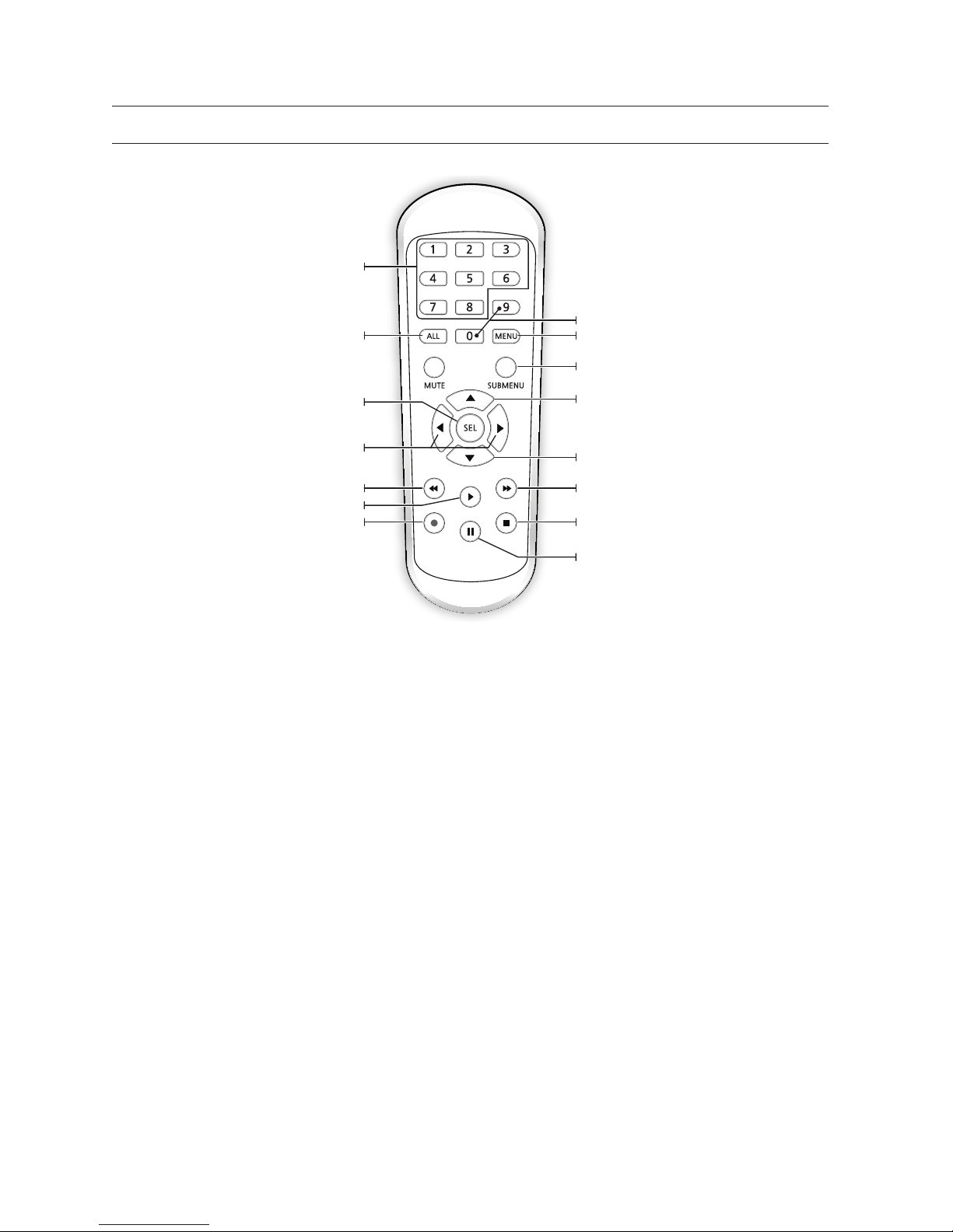
REMOTE CONTROLLER
Operation of remote controller
M
`
There is no function of Mute button.
Get Close to NVR
6_ Get Close to NVR
ALL
Multiple display mode
SEL
Select key/Edit key
Rewind key
Channel select Numeric key
Record key
Enter into record search menu/Play key
MENU
Enter into Main menu/Exit
SUBMENU
Go to Submenu
Up arrow key
Numeric key
Down arrow key
Forward key
Stop manual record; stop playing
Pause/Step forward key
Left/Right key; Decrease/Increase parameter value of
control bar.
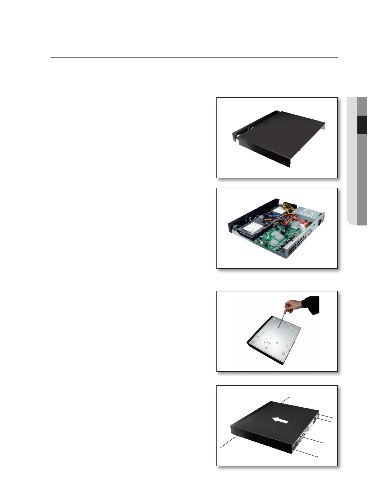
INSTALL HARD DRIVE
M
`
Do not remove the hard drive when NVR is operating.
Installation of Hard Drive
1. When power supply is disconnected, remove the screws at both
sides with screwdriver, then remove the screws on the rear board,
and then remove top cover of NVR.
2. Connect data and power cables of hard drive to motherboard.
Mount the hard drive by mounting it onto the rack and connecting
the power and data cables. Two groups of screw mounting
holes are provided in the base frame of the NVR, respectively for
installation of 3.5' hard drive and 2.5' hard drive. User should make
selection based on their hard drive size.
3. First mount the screws onto the rear board and then mount the
sides.
English _7
● GET CLOSE TO NVR
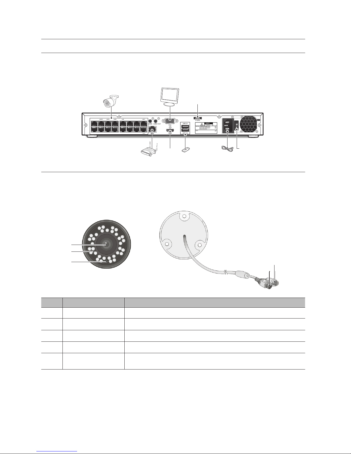
CONNECT EXTERNAL EQUIPMENT
Connect the cameras to the NVR via the network cables. If you choose not to power the cameras via the LAN ports, be sure to use
a 12V power adapter for power each camera.
Connect your monitor to the NVR using a VGA or HDMI cable to its respective port. Connect the NVR to the power cable that’s
supplied with the system.
CONNECT CAMERA
Connecting the Camera (SNC-4241BE)
Equipped with the IR LED and the illumination sensor, the camera enables you to monitor at all times, day and night. The camera is
suitable for both indoor and outdoor use.
Do not fully expose the camera to rain. The camera must be installed under a shelter to avoid exposure to excessive rain or moisture.
SN Name Description
a
Lens 3.6mm focal length enables you to monitor at a wider field of view.
b
IR LED Infrared LED lights are controlled by the illumination sensor.
c
Illumination Sensor Detects incoming light to control the IR LED.
d
IPC Network Port Connect to NVR via POE port or switch.
e
Power Cable
Use to power the camera if you would l like to power up the camera by using separate DC 12V power
adaptor.
Get Close to NVR
8_ Get Close to NVR
c
d
e
b
a
AC 100
240~IN
VGA
LINEIN AUDIO OUT
WAN
HDMI
LAN1
LAN2
LAN3
LAN4
LAN5
LAN6
LAN7
LAN8
LAN9
LAN10
LAN11
LAN12
LAN13
LAN14
LAN15
LAN16
CAUTION
RISK OF ELECTRI SHOCK
DO NOT OPEN
CAUTION : TO REDUCE THE RISK OF ELECTRICAL SHOCK
DO NOT OPEN COVERS. NO USER SERVICEABLE
PARTS INSIDE. REFER SERVICING TO QUALIFIED
SERVICE PERSONNEL.
WARNING : TO PREVENT FIRE OR SHOCK HAZARD. DO NOT
EXPOSE UNITS NOT SPECIFICALLY DESIGNED
FOR OUTDOOR USE TO RAIN OR MOISTURE.
e-SATA
USB 3.0
USB 2.0
e-SATA
HDMI
Power Switch
CONNECT NVR
The following figures are based on Model SNR-D5401.
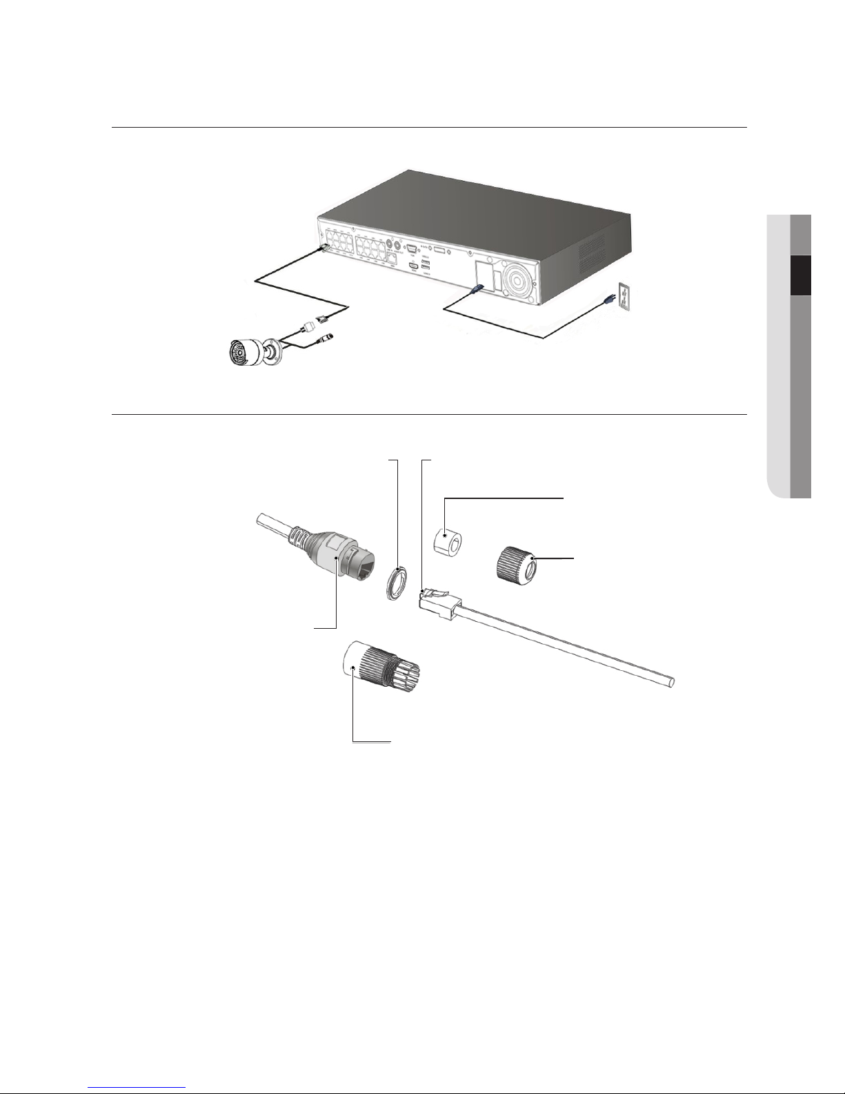
HOW TO ASSEMBLE THE WATERPROOF RJ-45 COUPLER
The following figures are based on Model SNR-D5401.
English _9
● GET CLOSE TO NVR
Waterproof rubber gasket(Female) RJ45 male connector
Fastening rubber gasket
(male)
Fastening back cover
RJ45 connector protector cap
RJ45 female modular jack(mold)
1. Insert the LAN cable through each component as shown below:
Fastening back cover -> Fastening rubber gasket -> RJ45
connector protector cap
2. Insert the fastening rubber gasket into the RJ45 protector cap so
the inner diameter of the fastening rubber gasket is tightened when
the back cap is screwed on.
Get Close to NVR
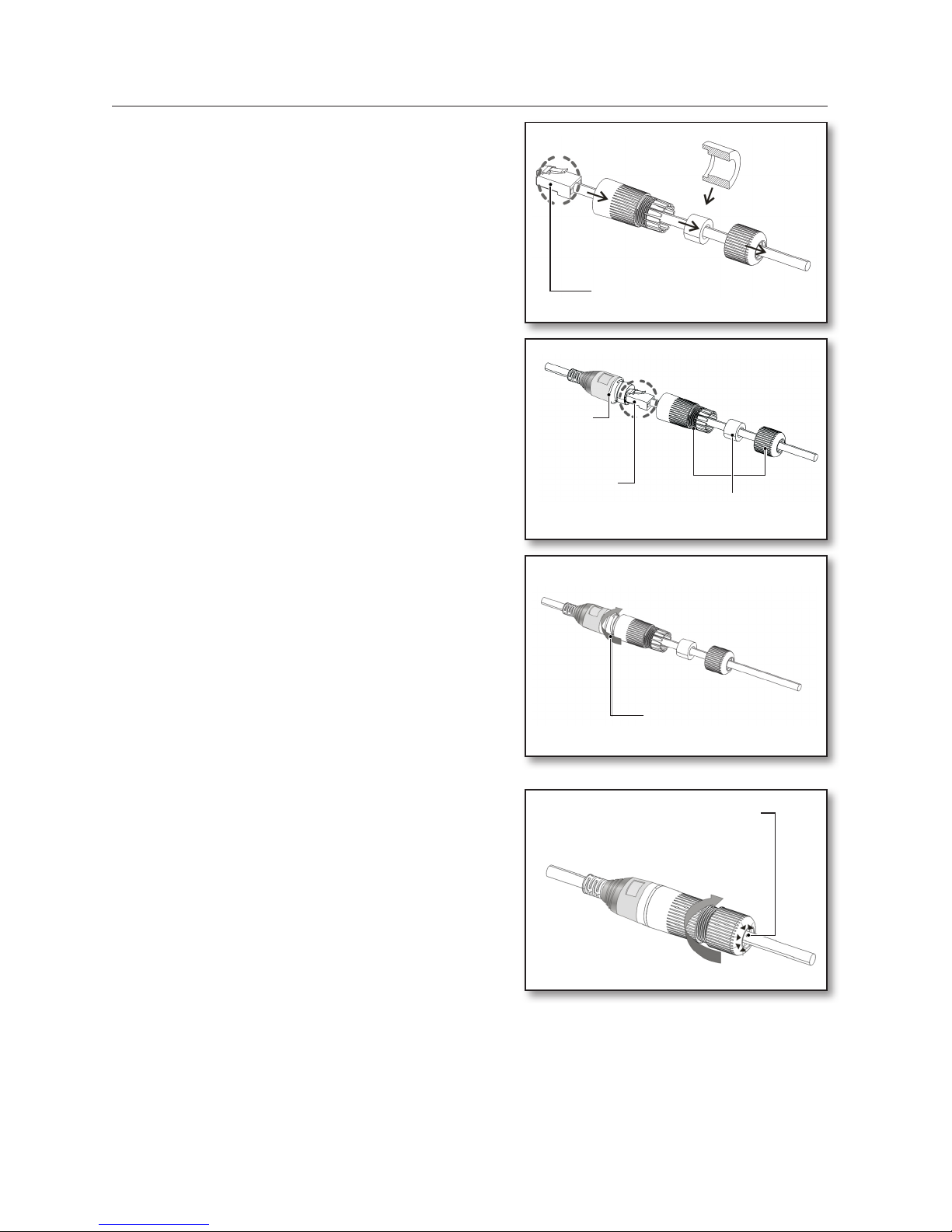
10_ Get Close to NVR
RJ45 connector protector cap
RJ45 male connector
* (Caution) Gasket
direction
RJ45 connector protector cap
Connect the RJ45
male and
female
connectors
Waterproof
rubber
gasket
(Female)
Keep fastening rubber gasket
separate
Tightly screw the protector cap
Tightly screw the back cap clockwise
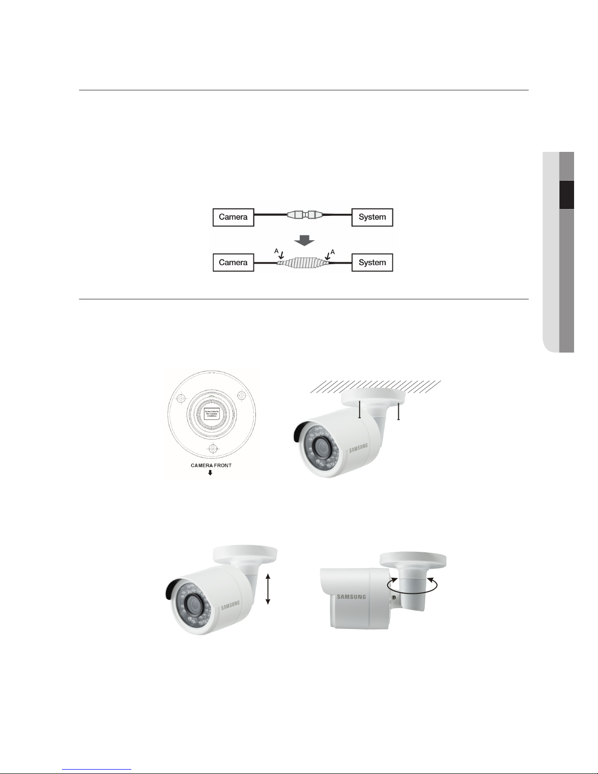
CABLE PROTECTION
1. As there may be direct leakage to the external cables when installed outside, please use waterproof butyl rubber tape to
protect the cables.
2. Wrap the cable jacket (Area A) and the cable connectors with waterproof (butyl rubber) tape so that more than half of the
butyl rubber tape is tightly overlapped.
`
If the cable jacked in not wrapped properly, water will directly leak into the connectors.
`
Waterproofing butyl tape is made of butyl rubber which extends twice its normal length.
`
If the power cable terminal is not in use, wrap it with waterproofing tape.
INSTALLING THE CAMERA
The camera can be installed on the wall, ceiling, shelf or a desired position using the provided mounting bracket.
1. Adhere the installation template onto the ceiling and use it as installation locating tool. (Please refer to Page 14 of Quick
Guide.)
2. Choose an installation site that can sufficiently support the weight of the camera to be installed.
3. Attach the camera bracket to the wall using the supplied screws.
4. Adjust the direction of the camera to the desired direction, and tighten the bracket.
5. Adjust the camera angle as needed.
6. Connect the camera cable to the camera.
J
`
Take caution when installing the camera outdoors because the cable connectors may be wet with moisture or with dirt buildup.
`
Although the camera is IP66 rated, direct exposure to water or moisture may cause problem such as condensation.
English _11
● GET CLOSE TO NVR
SYSTEM INITIALIZATION
After connecting the NVR power cable to the wall outlet,press the power button
and the theinitializing screen will appear.
M
`
The illustration in the user manual may not be the same as the menu interface in your
monitor. All the illustrations are for users’ reference.
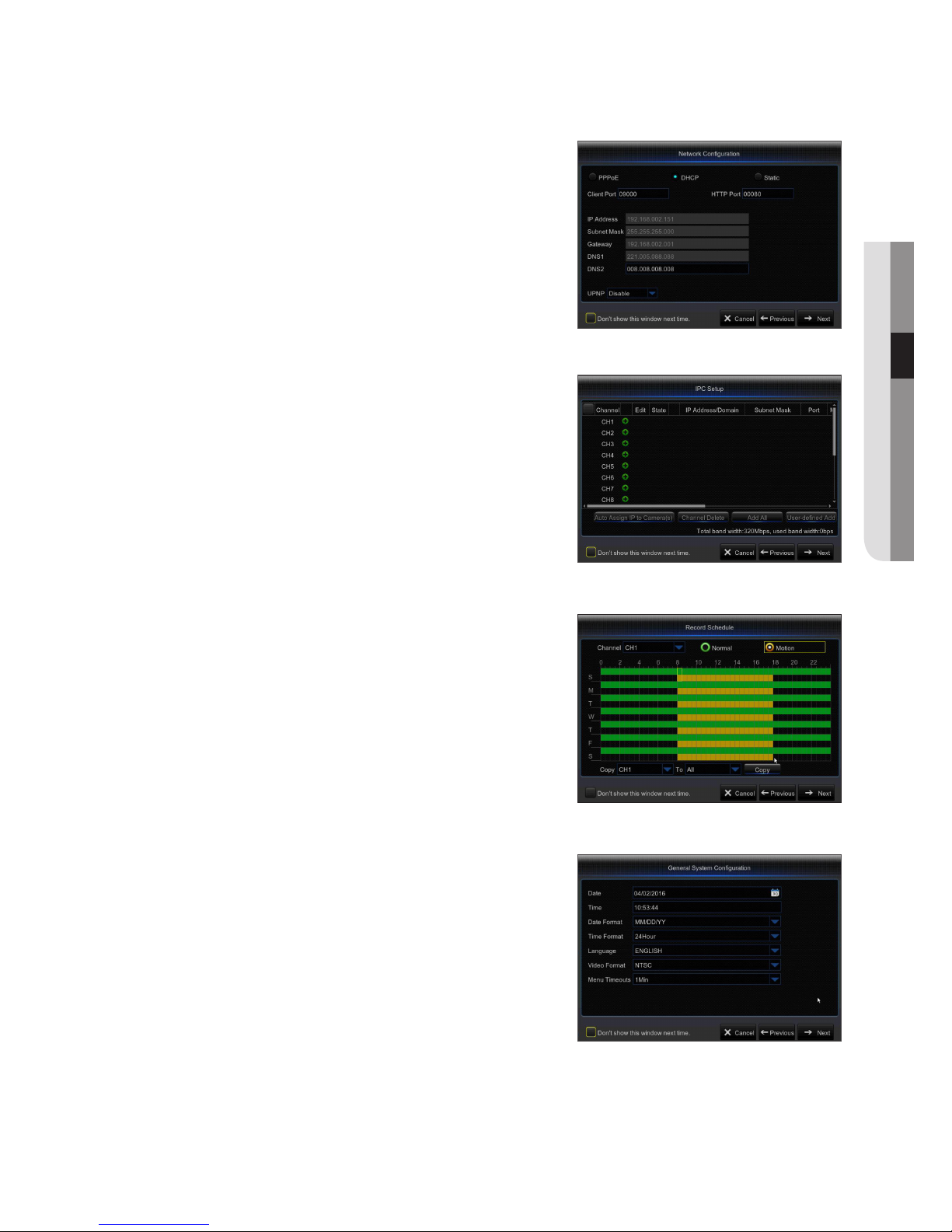
STARTUP WIZARD
After the NVR Startup is completed, the Startup wizard will be displayed. If you do not want to make any additional changes to your
settings when it reboots, check “To disable Startup Wizard after reboot”.
Wizard setting menu includes Homepage, Network setup, IPC setup, Record Schedule and hard disk maintenance.
•
Homepage
•
Admin password setting
•
Hard drive management
•
Network setup
•
IPC setup
•
Video recording Schedule
•
General system configuration
•
E-mail setting
•
DDNS setting
1.
Set Admin Password
Please create a username and password for your NVR. Password MUST
be 8~13 characters long. When password is 8~9 characters long, it
should be with at least a combination of letters, digits and special symbols. If it is 10~13 characters long, it should be with at least a combination
of two types of characters. 4 or more contiguous or repeated characters
or key arrangement are prohibited, for example 1111, 1234, abcd, qwerty.
Retype password: Re-enter the password set above.
2.
Hard Drive Management
New hard drive(s) connected must be formatted before use. Upon
connection, it will indicate to format new hard drive. Click on “Select” to
select the unformatted hard drive. Click on “Format HDD” to pop up the
user login window and enter the password to log in. A notice window will
indicate “Entire Data Will Be Erased. do You Want To Continue?”. Click
“OK” to format the disk. When the progress bar is complete, the formatting process is completed.
12_ NVR Boot up
NVR Boot up
3.
Network setup
In DHCP mode, the router will automatically allocate IP address to the
NVR. If the NVR fails to obtain an IP address, refer to the NVR Router
Guide. If the problem still cannot be resolved, contact technical support.
4.
IPC Setup
User may add and delete IPC.
5.
Video Recording Schedule
Select the channel and the date to be set. One week’s schedule can be
set. The record “schedule” of the current channel can be copied to any
other channel or all channels.
M
` If there is no color in the record menu and record search, there is no recording
saved.
` “Green” stands for normal record and “yellow” stands for motion record.
6.
General System Configuration
You can set date, time, date format, time format, language, video format
and menu timeouts.
English _13
● NVR BOOT UP
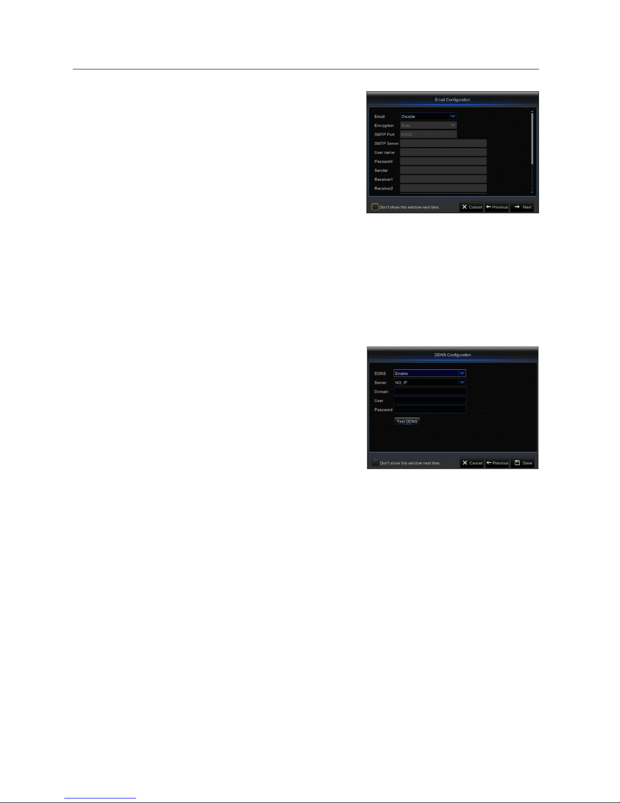
7.
Email Setting
Receive or Send NVR alarm email and set parameters like email address,
SSL, email enable, and interval.
•
Encryption: Disable, SSL, TLS and Auto optional. Auto means it can
detect the encryption type automatically. It is recommended to set the
encryption type as Auto.
•
SMTP Port: Mail sending port used by SMTP (Simple Mail Transfer
Protocol). Server is generally Port 25 or Port 465 when SSL is used by
Gmail.
•
SMTP Server: Enter the address of the server for the mailbox in use.
•
User Name: Enter a server to connect to. For example, email “aaa@
gmail.com” should correspond to server “smtp.gmail.com”
•
Password: Enter the password of the SMTP server user.
•
Sender Address: Sender’s email address, which must correspond to the server used. For example, email “aaa@gmail.
com” should correspond to server “smtp.gmail.com”.
•
Receiver 1/2/3: Recipient’s mail address, used to receive alarm image and message from NVR side. If system alarms
continually and sends email images frequently, save the images to another location or remove them, so as to avoid
excessive space occupation and thereby affect your normal use of mailbox.
•
Time Interval: A mail will be sent every three minutes by default. If the time interval for mail notification is set too short,
email server may deem mails as junk mails, so they cannot be transferred normally.
•
Click on “Test Email”. If connection succeeds “Test E-mail” will be sent out.
8.
DDNS SETTING
User may set DDNS under network type of PPPoE/Static/DHCP after applying dynamic domain service. User may remotely access NVR through
domain by using browser in the form of http://applied domain: mapped
HTTP port number when using DDNS domain name to access NVR.
•
Server address: Select dynamic domain name server provider.
Available domain name servers (HANWHA-SECURITY, DDNS_3322,
DYNDNS, NO_IP, CHANGEIP, DNSEXIT)
•
Domain name: Dynamic domain name of the host obtained from
dynamic domain name service provider upon registration, for example,
nvr2016.no-ip.org.
•
User Name: The user name registered upon application for dynamic
domain name.
•
Password: The password set upon registration.
•
Click on “Test DDNS”. If connection is made, it will indicate “DDNS Test is Successful!”. Perform remote access to the
NVR by using dynamic domain name, for example, http://ddns.hanwha-security.com/snb5000: HTTP port number (e.g.
19010)
9.
Click on “Save” to finish setting of startup wizard.
NVR Boot up
14_ NVR Boot up
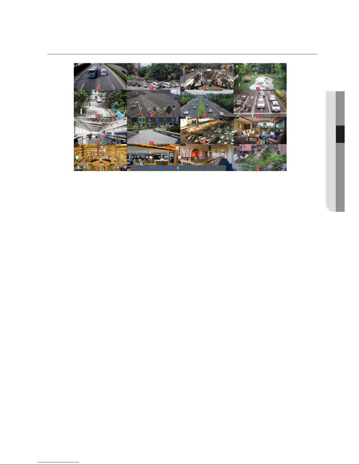
MAIN INTERFACE
J
`
When there is no HDD pre-installed or pre-installed HDD is not formatted, buzzer will be activated. If you want turn off the buzzer, please go to
[Advanced -> Events -> Disk Full or Disk Error] to set the buzzerto ‘Off’.
English _15
● NVR BOOT UP
NVR Menu
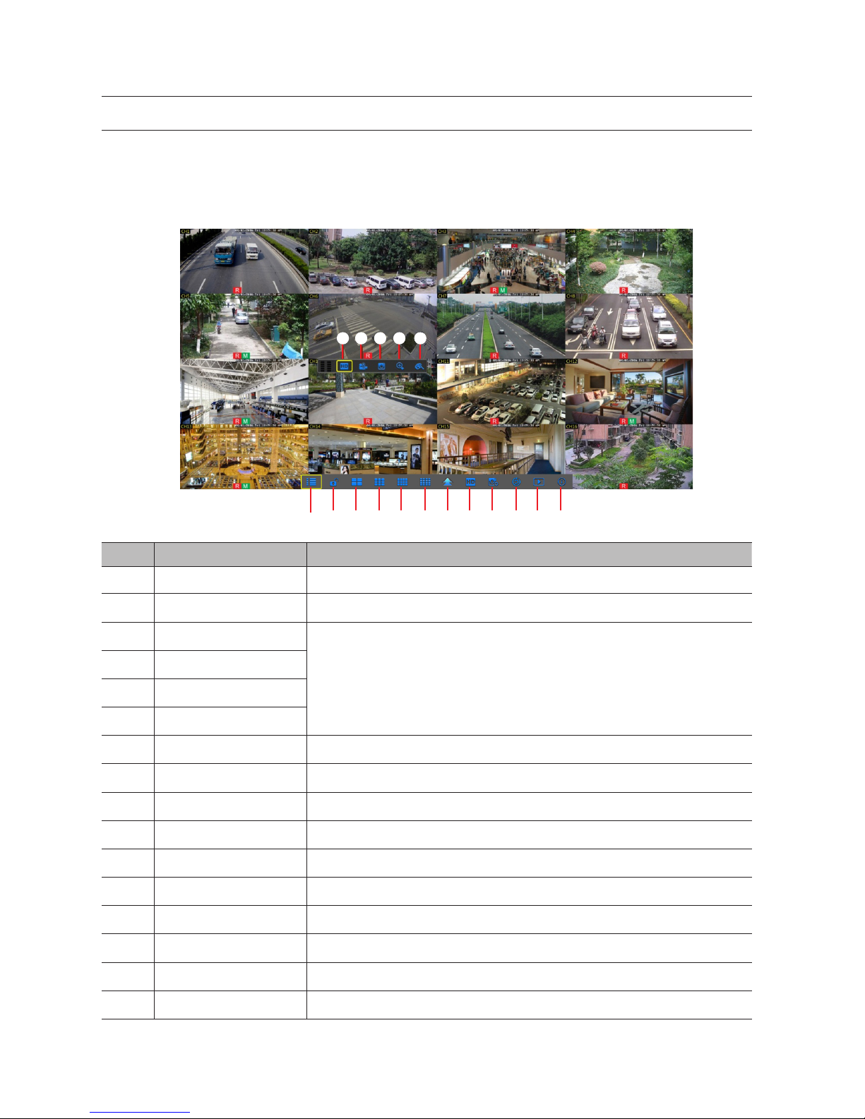
POPUP MENU
After finishing system initialization, right click the mouse topreview interface or slide the mouse to the bottom of screen to enter into
Pop-up Menu. Now you could perform parameter setting and operate on Main Menu, Multi-Pics, Record Search, Sequence and
Stream switching.
The options in the pop-up menu may be varied slightly according to different parameter settings. The options in the menu will be
explained in detail in the following chapters.
SN Component Name Function
1
Main Menu Access the main menu.
2
Manually Lock Screen Sign out or access sign-in page.
3
4-Channel Layout
Display four channels of video/ Display nine channels of video/Display twelve channels of video/ Display
sixteen channels of video
4
9-Channel Layout
5
12-Channel Layout
6
16-Channel Layout
7
More Layout Displays different channel layout
8
Stream Switch Switch between Main Stream and Sub Stream
9
View Image Quality Switch among Realtime, Balanced and Smooth
0
SEQ Start or stop SEQ
!
Playback Replay video recorded
@
Information System Information.
#
Record Enable or disable manual recording
$
Instant Playback Display channel name Quick playback of video of last 5 minutes
%
Zoom Hold and drag mouse cursor to select a frame of current video to zoom in
^
Color Adjust the color of video
1 2 3 4 5 6 7 8 9 0 ! @
#7 $ % ^
16_ NVR Menu
MAIN MENU GUIDE
Parameter
Record Search
Device
System
Advanced
Shutdown
Display
Record
Network
Alarm
General
HDD
Events
General
Users
Log
Info
Events
Maintain
IP Channels
Record
Network
Live
Record Schedule
Switch
Output
Mainstream
Email
Image control
Substream
Email Schedule
Privacy Zone
Mobliestream
DDNS
Motion
General
DST
NTP
Main Menu
Info
Channel Info
RTSP
Record Info
English _17
● NVR MENU

MAIN MENU
On LIVE mode, click the mouse button, or [Menu] button on the remote controller, or
click [ ] icon on the toolbar to enter the main menu screen.
If system interface is locked, please enter the password to log in. If you forgot your
password, please contact technical support.
In Main Menu mode, you can make adjust the settings for Parameter, Record
Search, Device, System, Advanced and Shutdown.
Parameter
Display
IP Camera
Go to "Main Menu" ; "Parameter" ; "Display" ; "IP Camera" to enter into the interface.
•
Channel: IPC camera channel.
•
Edit: Modify the name and location of channels, change other IPC or
protocols, etc.
•
State: Display IPC on-line state.
•
: Modify IP address of IPC camera.
•
IP Address/Domain: IP address of the IPC connected of the channel.
•
Subnet Mask: IPC camera Subnet mask.
•
Port: Connection port number of the currently set IPC.
•
Manufacturer: Manufacturer for different IPC.
•
Device type: Add IPC with different protocols.
•
Protocol: Private
•
MAC Address: Physical address for device.
•
Software: Display current version of IPC.
•
Auto Assign IP to Camera(s): Auto Assign IP to IPC.
•
Channel Delete: Delete IPC
•
Add All: Add All IPC
•
User-defined Add: User-defined
NVR Menu
18_ NVR Menu
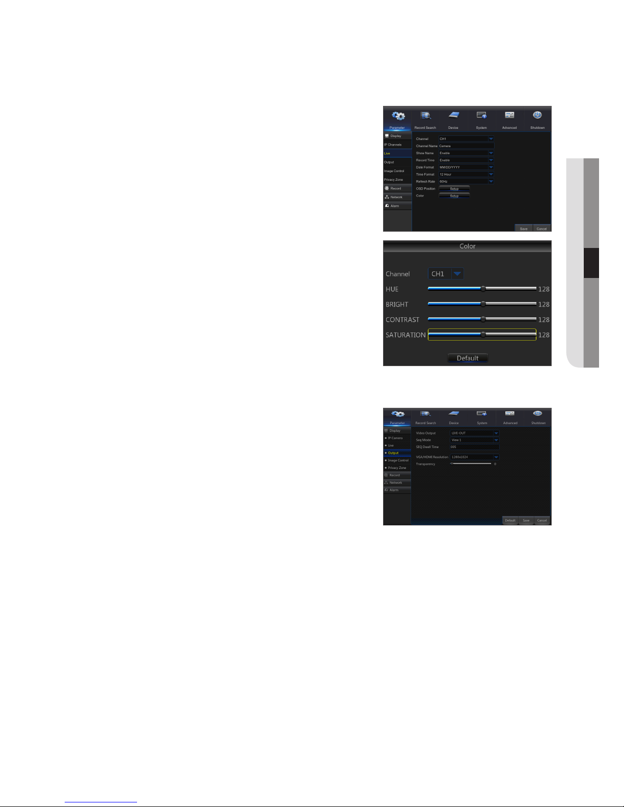
Live
Go to "Main Menu" ; "Parameter" ; "Display" ; "Live" to enter into the interface.
•
Channel: Select channel number.
•
Channel Name: Name marked on IPC.
•
Show name: Enable or Disable display channel name.
•
Show Time: Enable or Disable display time.
•
Date Format: Set date format such as m/d/y or y/m/d and d/m/y.
•
Time Format: 12 hour or 24 hour.
•
Refresh Rate: IPC Refresh Rate 50Hz or 60Hz.
•
OSD Position: Freely set the position of IPC name and time.
•
Color: Adjust the hue, brightness, contrast and saturation of the IPC of the
channel.
Output
Go to "Main Menu" ; "Parameter" ; "Display" ; "Output" to enter into the interface.
•
Video Output: Live Output
•
Sequence Mode: Set sequence mode
•
SEQ Dwell Time: Sequence dwell time is set 5 seconds by default. User
may set it as required.
•
VGA/HDMI Resolution: VGA output or HDMI output. Including1024×768,
1280×1024, 1440×900, 1280×720, 1920×1080, 2560×1440, 3840×2160.
•
Transparency: Set the transparency of the menu in the range of 0—128.
English _19
● NVR MENU
 Loading...