

Samsung SNC-1300 User Manual
Before installing and operating this product,
please read this manual thoroughly.
Megapixel Network Camera SNC-1300
User Guide
English
NETWORK CAMERA User Guide
2
NETWORK CAMERA User Guide
3
a brand integrated into Samsung’s network products, stands for a convenient world
(Polis) made safe (Police) through Samsung’s superior network performance (Internet Protocol). iPOLiS
network cameras and servers are our advanced security systems providing versatile network options by
default, including an Ethernet interface for easy internet connection, high-quality image transfer options
using MPEG-4, M-JPEG a Web Viewer, two-way audio, and remote control capacity.
FCC Compliance Statement
NOTE :
This equipment has been tested and found to comply with the limits for a Class A digital
device, pursuant to part 15 of the FCC Rules. These limits are designed to provide reasonable
protection against harmful interference when the equipment is operated in a commercial
environment. This equipment generates, uses, and can radiate radio frequency energy and, if not
installed and used in accordance with the instruction manual, may cause harmful interference to radio
communications. Operation of this equipment in a residential area is likely to cause harmful
interference in which cause the user will be required to correct the interference at his own expense.
Correct Disposal of Batteries in this Product
(Applicable in the European Union and other European countries with separate
battery return systems.)
marked, the chemical symbols Hg, Cd or Pb indicate that the battery contains mercury, cadmium or
lead above the reference levels in EC Directive 2006/66. If batteries are not properly disposed of, these
substances can cause harm to human health or the environment. To protect natural resources and to
promote material reuse, please separate batteries from other types of waste and recycle them through
your local, free battery return system.
The rechargeable battery incorporated in this product is not user replaceable.
For information on its replacement, please contact your service provider.
This marking on the battery, manual or packa ging indicates that the batteries in this product
should not be disposed of with other household waste at the end of their working life. Where
■
Preface
Thank you for purchasing this SNC-1300 camera.
This user’s manual describes how to use the high-resolution network camera. Also ‘product’ in
this document indicates high-resolution network camera. The user who installs and operates the
product shall be aware of this manual and other manuals referenced by this manual before the
installation and operation and use it properly. This manual and the software and hardware
explained here are protected by copyright law.All copying, reprinting and translating to other
languages of part of or all of its contents without permission of Samsung Techwin Co., Ltd. are not
allowed, except for fair use within the scope of copyright law.
Samsung Techwin cares for the environment at all product manufacturing stages,
and is taking measures to provide customers with more environmentally friendly
products.
The Eco mark represents Samsung Techwin’s devotion to creating environmentally
friendly products, and indicates that the product satisfies the EU RoHS Directive.
■
Product Warranty and Limited Liability
The manufacturer of this product is not responsible for the sale of the product, nor does the
manufacturer delegate such responsibility to a third party.
The product warranty does not cover accidents, negligence, abuse, or improper use for the
item in whole or in any part. Additionally, the manufacturer does not provide warranty for any
additional part or piece that was not supplied by the manufacturer.
The product warranty period is for two years from the purchase date. However, the warranty
does not cover any of the following problems, and a nominal service fee will be charged if:
· Product has been improperly used or handled by user.
· Product has been disassembled and/or altered by user.
· Product has been damaged by connecting a power supply with improper specifications.
· Product has been damaged due to an “Act of God” (fire, flood, tsunami, natural disaster, etc.).
· To replace expendable components.
· Product is malfunctioning due to an unstable network connection.
■
This instruction manual is based on the product installed with the
firmware version at 1.0.0.
Correct Disposal of This Product
(Waste Electrical & Electronic Equipment)
to the environment or human health from uncontrolled waste disposal, please separate this from other
types of wastes and recycle it responsibly to promote the sustainable reuse of material resources.
Household users should contact either the retailer where they purchased this product, or their local
government office, for details of where and how they can take this item for environmentally safe
recycling. Business users should contact their supplier and check the terms and conditions of the
purchase contract. This product should not be mixed with other commercial wastes for disposal.
(Applicable in the European Union and other European countries with separate collection
systems.) This marking shown on the product or its literature, indicates that it should not be
disposed with other household wastes at the end of its working life. To prevent possible harm
NETWORK CAMERA User Guide
4
NETWORK CAMERA User Guide
5
Caution
Using the Product
· Opening or removing the product case will expose you to the risk of electric shock; do not open
or remove the case unless you are a qualified technician.
· Please keep the product within the recommended temperature and humidity range.
· To prevent electrical fire, do not connect multiple power cords to a single outlet.
· Do not place heavy objects or vessels containing water on the unit since it can cause serious
malfunctions.
· Do not install the product in a location where it may be exposed to extreme heat or cold.
· Using the product in extremely hot (over 50ºC) or extremely cold (under -10ºC) environments
may degrade picture quality and/or cause product malfunctions.
· Do not install the product in areas with flickering illumination. Severe fluctuations in ambient
luminance, such as flickering of old fluorescent lights, may cause the product to malfunction.
· Do not drop the camera or subject it to physical shock. It may damage the product.
· Do not drop the camera or subject it to physical shock. It may damage the product.
· Avoid touching the camera lens. It is the most important component of your product. Be careful
not to smear it with fingerprints.
· Do not install the camera where it may be exposed to rain, water, and/or radioactivity. Water may
enter the product and cause malfunctions.
· Do not open or disassemble the product. Opened or disassembled products are not covered by
the warranty.
· Inspect your network environment before connecting the camera to the network.
· Do not use power adapters other than the one that is provided with the camera.
· Please review local, state, and federal information security laws before using this product as
part of your security system.
Warning Symbols Warning Symbols
· Do not use this item in a location containing propane gas, gasoline, or other flammable
substances to avoid risk of explosion or fire.
· To avoid the risk of electric shock, do not touch the power plug with moisture on your hands.
· Do not pull on the power plug with any force; a damaged plug may cause electric shock or fire.
· Do not force an RJ-45 cable into the product connection port when connecting to a network.
· Stop using the product immediately if smoke or an unusual amount of heat is emanating from
your camera. Failure to do so may result in fire.
· To avoid the risk of an explosion, the internal Lithium battery must be replaced only with an
identical, or a fully compatible, product. The internal lithium battery requires specialized skills for
replacement; it must be replaced by a technician, not by the user. For assistance, please contact
our service center. Obsolete batteries must be properly retired or recycled to protect the
environment.
· Do not expose the battery to heat or place it in fire; short-circuiting or disassembling the battery
is also hazardous.
· Do not recharge the battery.
Disassembly and Cleaning
· There is a risk of malfunction, shock, and other dangers. Do not disassemble or attempt to fix or
alter the product yourself.
· Do not clean the product with water, paint thinner, or other organic solvent as doing so may
cause product malfunctions and/or electric shock. When cleaning the product, use a dry cloth to
wipe the exterior of the device.
Warning
Installing the Product
· Please check the power outlet voltage before you connect the power to the outlet.
· Make sure that the product is switched off before you install it.
· There is a risk of shock or fire; be sure to avoid setting up in places with high humidity.
· The product must be grounded to reduce the risk of electric shock.
· Self-installation of this product is prohibited.
Installing this product requires experience and specialized skills; attempting to install the
product by yourself exposes you to the risk of fire and/or electrical shock. Please contact your
vendor for installation.
· Do not install the product on a structurally unsound surface.
The product may detach from the surface and fall down.
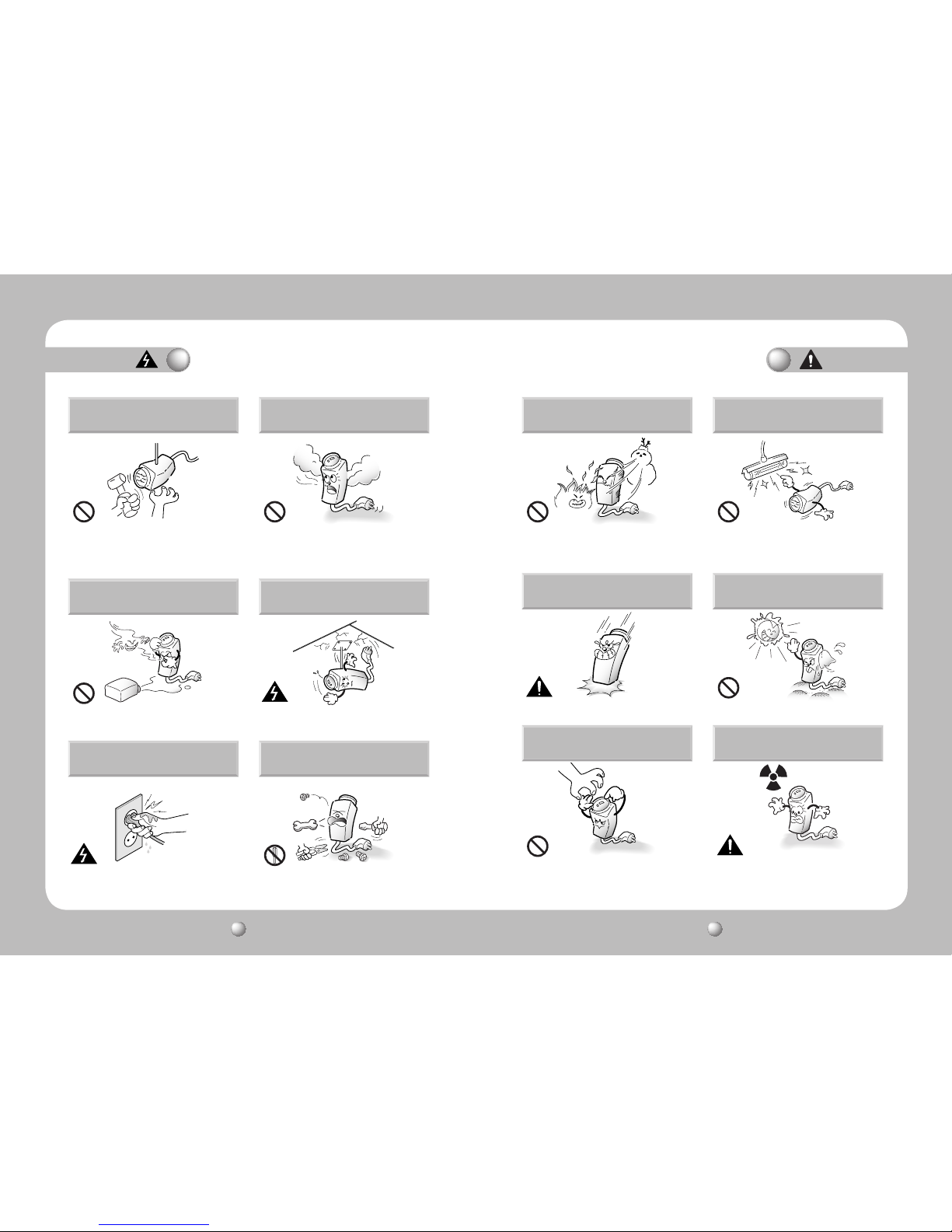
The following section contains vital information that helps protect the safety of the user
and prevent property damage/loss. Please read it carefully for safe and proper use of
your product.
This warning symbol indicates death, grave personal injury, and/or damage
to property as consequences for failure to comply.
This caution symbol indicates damage to the equipment, installed programs,
and/or contained data as consequences for failure to comply.
This symbol indicates an informative appendix to a certain section of this
user’s manual.
Legend: Warning and Caution Symbols
NETWORK CAMERA User Guide
6
NETWORK CAMERA User Guide
7
Table of Contents
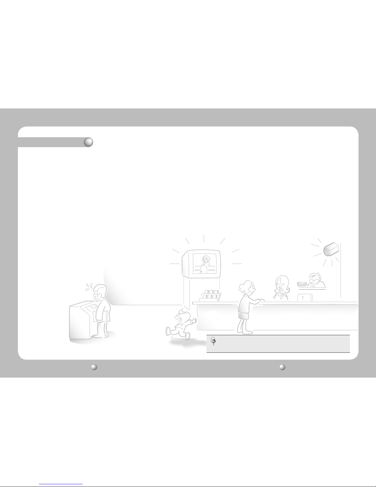
·
For instructions on using the SVM-S1 program, please refer to the enclosed
SVM-S1 Quick Guide and the user's manual file on the CD.
Note
Preface ································································································ⅲ
Product Warranty and Limited Liability ·················································ⅲ
Warning Symbol ····················································································4
Warning ·································································································8
Caution ···································································································9
Factory Default Settings ······································································ 10
∙ Monitoring ··································································································10
∙ Video Setup ·································································································10
∙ PTZ ··············································································································12
∙ Config ·········································································································12
∙ System ········································································································14
Ch1. SNC-1300 Network Camera Summary ·········································16
1.1. SNC-1300 Network Camera Introduction ················································16
1.2. Features ································································································16
Ch2. Product Information ······································································ 18
2.1. Package Contents ··················································································18
2.2. Part Names and Functions ·····································································18
2.2.1. Front ·····································································································18
2.2.2. Side ······································································································19
2.2.3. Bottom ··································································································20
2.2.4. Back ····································································································21
2.3. PC Requirements ···················································································22
Ch3. Installing Camera & Network Setup ··········································· 23
3.1. Installing Lens ······················································································ 23
3.2. Connecting Monitor ·············································································· 26
3.3. Power Input ··························································································· 27
3.4. Connecting External Control Terminals ·················································· 28
3.5. Network Configuration & Connection via Website ··································· 32
Ch4. Using Web Viewer ········································································ 37
4.1. Using Web Viewer ···················································································37
4.1.1. Login ····································································································37
4.1.2. Monitoring Screen ·················································································38
4.2. Administrator Page ················································································ 42
4.2.1. Video Setup ···························································································42
4.2.1.1. Video / Audio ····················································································· 42
4.2.1.2. Streaming ························································································· 45
4.2.1.3. Motion Detection ··············································································· 51
4.2.1.4. Privacy ······························································································ 52
4.2.1.5. Camera ····························································································· 53
4.2.1.6. Record ······························································································ 57
4.2.1.7. Replay / Backup ················································································ 58
4.2.2. PTZ SETUP ····························································································59
4.2.3. Config Page ··························································································60
4.2.3.1. Network ···························································································· 60
4.2.3.2. IP Filtering ························································································· 68
4.2.3.3. Alarm Sensor ···················································································· 69
4.2.3.4. E-mail-FTP (Alarm) ············································································ 71
4.2.4. System ·································································································72
4.2.4.1. Product Info ······················································································73
4.2.4.2. User ·································································································· 74
4.2.4.3. Time ································································································· 76
4.2.4.4. Log Message ···················································································· 77
4.2.4.5. Upgrade ···························································································· 78
Ch 5. Troubleshooting ··········································································79
Product Specification ·········································································· 81
Dimension ····························································································· 83
MEMO ··································································································· 84
NETWORK CAMERA User Guide
8
NETWORK CAMERA User Guide
9
Caution
Warning
Self-installation of this product is
prohibited.
Installing this product requires experience and
specialized skills; attempting to install the product by
yourself exposes you to the risk of fire and/or electrical
shock. Please contact your vendor for installation.
Stop using the product immediately if smoke or an
unusual amount of heat is emanating from your camera.
Failure to do so may result in fire.
Do not install the product in a damp area, or where
it may be exposed to flammable liquids and/or gas.
Product malfunctions, electric shock, and/or fire
may occur.
Do not install the product on a structurally
unsound surface.
The product may detach from the surface and fall
down.
Do not handle the power plug with wet
hands.
It may cause electric shock.
Do not disassemble the product or place
foreign objects into the product.
Product damage and/or fire may occur.
Do not install the product in a location where
it may be exposed to extreme heat or cold.
Using the product in extremely hot (over 50ºC) or extremely cold
(under -10ºC) environments may degrade picture quality and/or
cause product malfunctions. When using the product in hot
areas, be sure to provide adequate ventilation for the product.
Do not install the product in areas with
flickering illumination.
Severe fluctuations in ambient luminance, such as
flickering of old fluorescent lights, may cause the
product to malfunction.
Do not drop the product, or subject it to
strong shocks or vibration.
It may damage the product.
Never point the camera directly at the
sun, or other powerful sources of light.
You may severely damage the charge-coupled
device (CCD).
Do not touch the camera lens.
It is the most important component of your product.
Avoid contaminating the lens with fingerprints or
other pollutants.
Do not install the product where it may
be exposed to radioactivity.
Exposure to radioactivity will degrade the CCD and
cause malfunctions.
NETWORK CAMERA User Guide
10
NETWORK CAMERA User Guide
11
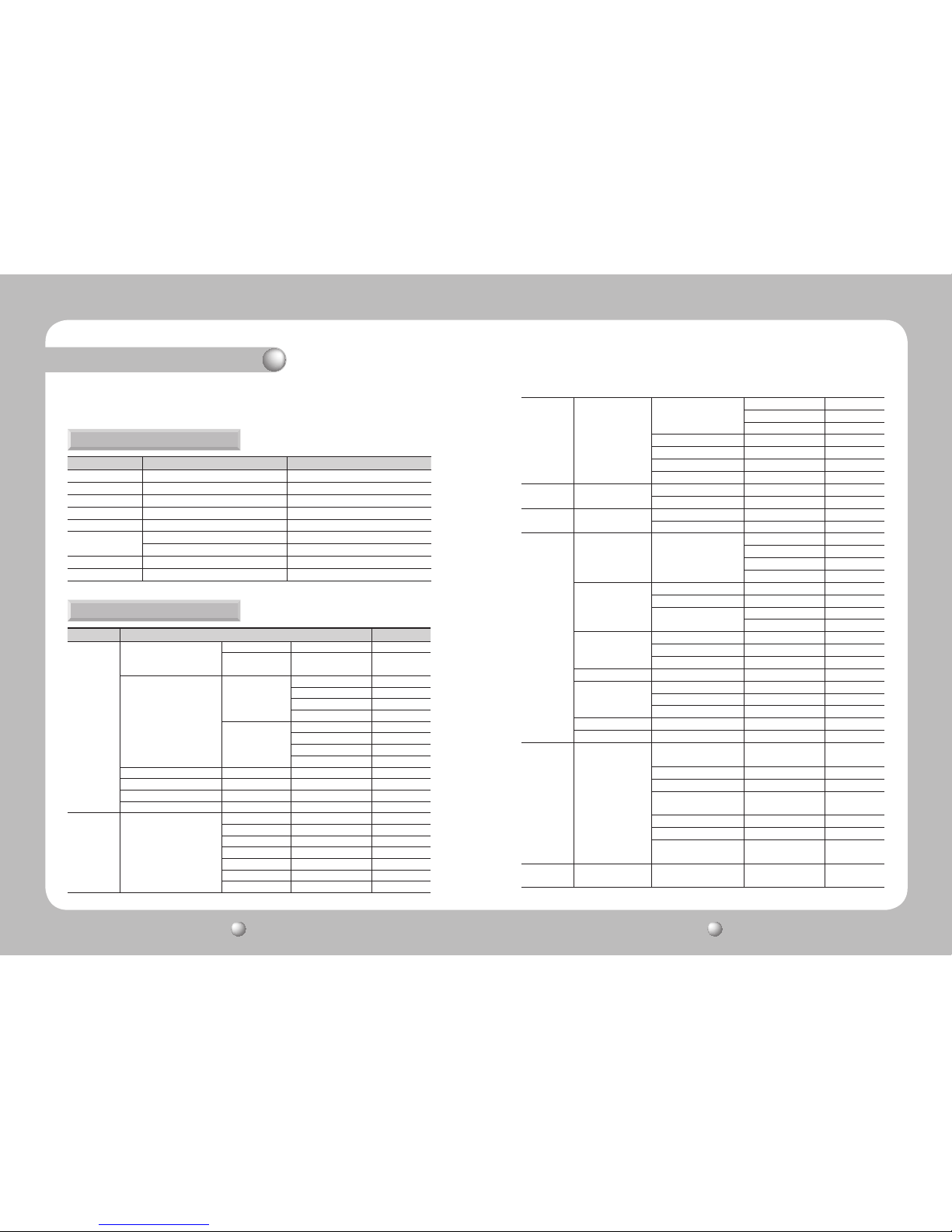
Factory Default Settings
The following are the factory default settings for the product.
Main Menu Sub Menu Default setting
1 Ch Display On
Flip Image Off
Stretch Image Off
Information On
Save Image Off
Basic Mode
Resolution Main
Compression MPEG - 4
PTZ Mode PTZ Speed 3
Relay Off
Main Menu Sub Menu Default setting
Video/Audio
Video
Mode 960P
Default Display
Stream
Main Stream
Stream
Main Stream
Resolution MEGA
Frame rate(MPEG-4) 10
Frame rate(M-JPEG) 5
Quality High
Sub Stream
Resolution CIF(Fixed)
Frame rate(MPEG-4) 20
Frame rate(M-JPEG) 5
Quality High
Audio-In Use
Audio-Out Use
Max User Connection 5
Mic. Sensitivity Low
Streaming
Continuous Jpeg Image
Transmission to FTP Server
(Jpeg CIFs.)
Use No Use
Frame Rate 1fps
Server Name server_name
Server Port 21
Home Directory /
User ID user_id
User Password
Streaming Streaming Engine
Service
RTSP/TCP No Use
RTP/UDP No Use
RTP/Multicast No Use
RTP/Multicast IP 224.0.1.1
RTP/Multicast Port 9000
Unicast Image Resolution Main
RTSP Standard Port(554) Use
Motion
Detection
Enable No use
Sensitivity 3
Privacy
Enable No Use
Blending Level 5
Camera
1. LENS LENS SETUP
DC/VIDEO
Brightness Level 30
Focus ADJ No Use
Shutter Level 1/60
2. EXPOSURE
SHUTTER SETUP A.FLK.60Hz
GAIN SETUP Low
SENSUP SETUP
Enable Use
Sens-Up Level X2
3. WHITE BALANCE
WHITE BALENCE SETUP ATW
RED Level 200
BLUE Level 35
4. DAYNIGHT DAY & NIGHT SETUP AUTO
5. IMAGE ADJ
FLIP SETUP On
MIRROR SETUP On
SHARPNESS SETUP 3
6. BLC BLC SETUP OFF
7. RESET OFF
Record Recording Setup
Target Stream
Main Stream
(MPEG-4)
Pre Alarm 1 sec
Post Alarm 5 sec
M-JPEG Recording
Frame Rate
N/A
MPEG-4 Recording Option 1 fps
Overwrite No Use
Warning
Message
No Use
Replay /
Backup
Replay / Backup Event Type ALL
Monitoring
Video Setup
NETWORK CAMERA User Guide
12
NETWORK CAMERA User Guide
13
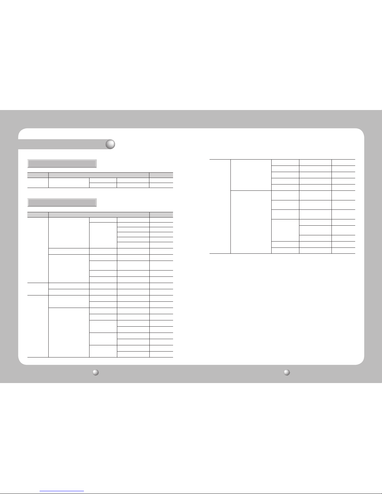
Main Menu Sub Menu Default setting
Pan / Tilt /
Zoom
Device Setup
Device ID 1
Mode SRX-100B
Main Menu Sub Menu Default setting
Network
Interface
LAN
LAN
IP Address 192.168.1.100
Net Mask 255.255.255.0
GateWay 192.168.1.1
DNS1 168.126.63.1
DNS2 168.126.63.2
Port Service Port 80
DDNS
Use No Use
Server
www.samsung
ipolis.com
ID
Password
IP Filtering
IP Filtering Use No Use
Default Policy Den y
Alarm Sensor
Digital In(Sensor) Setup
Use S1 Use
Type Type Normal Open
Digital Out(Relay/Alarm) Setup
Relay(R1) S1 No Use
Relay(Duration) 3sec 3sec
FTP
S1 No Use
MD No Use
Mail
S1 No Use
MD No Use
Recording
S1 No Use
MD No Use
PTZ
Config
Factory Default Settings
E-mail / FTP
(Alarm)
FTP Setup
Server Name server_name
Server Port 21
Home Directory /
User ID user_id
User Password
Email - Setup
Recipient E-mail
Address 1
mail_address1
Recipient E-mail
Address 2
mail_address2
SMTP Server Name
external_smtp_
server_name
Authentication
Use
ID
external_smtp_
id
PW
Mail Subject mail_subject
Mail Body mail_body
NETWORK CAMERA User Guide
14
NETWORK CAMERA User Guide
15
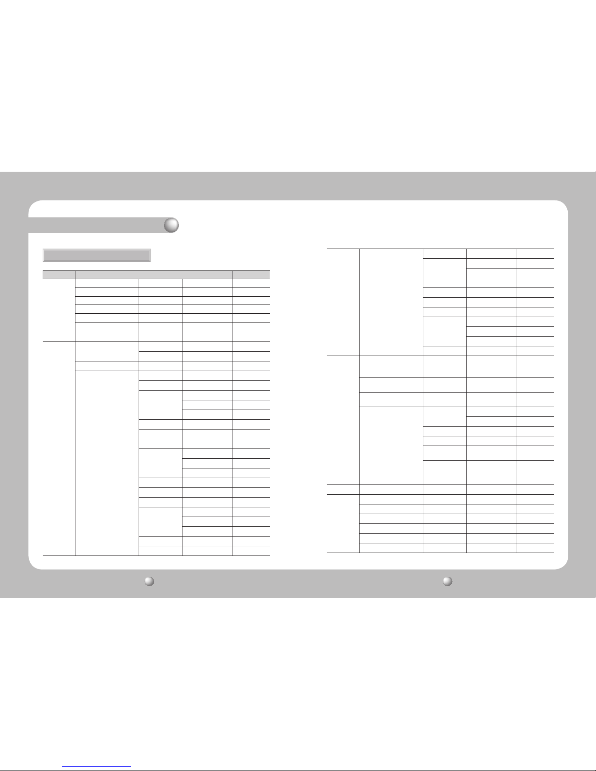
Main Menu Sub Menu Default setting
Product Info
Model SNC-1300
Mac Address
Device Name SNC-1300
Channel Name ch01cam
Location location
Description description
Memo memo
User
Administrator
Password Change
Type
Re-Type
Guest Setup Guest Access No Use
Current Users
User Name user1
Password user1
Control Level
Video Use
Control Use
Audio - In Use
Use No Use
User Name user2
Password user2
Control Level
Video Use
Control Use
Audio - In Use
Use No Use
User Name user3
Password user3
Control Level
Video Use
Control Use
Audio - In Use
Use No Use
User Name user4
User Current Users
Password user4
Control Level
Video Use
Control Use
Audio - In Use
Use No Use
User Name user5
Password user5
Control Level
Video Use
Control Use
Audio - In Use
Use No Use
Time
Current Time
2009-01-01
00:00:00
(+00:00)
Time Zone
(GMT) Greenwich
Mean Time
Device Name
Use Daylight Saving
Time
Use
Time Setup
Set Manually
Date
Time
Time Server Server1 pool.ntp.org
Time Server Server2 asia.pool.ntp.org
Time Server Server3
europe.pool.ntp.
org
Time Server Server4
north-america.
pool.ntp.org
Time Server Server5 time.nist.gov
Log message Syslog All
Upgrade/
Reboot
SNC-1300 Firmware 1.0.0
Current version
Module Version
Last Updated
Default Setting
Reboot
System
Factory Default Settings
NETWORK CAMERA User Guide
16
NETWORK CAMERA User Guide
17
Chapter 1. SNC-1300 Network Camera Summary
The SNC-1300 is based on the MPEG-4 codec technology which achieves both a high data
compression rate and high image quality. This advanced network camera is capable of
transferring high quality image data at a high frame rate and in real time over the network.
It is easy to install and use; you only need a network cable to install and connect it to your
network, and you can remote-control, monitor, command it online from anywhere, anytime.
The SNC-1300 network camera is provided with our proprietary embedded software
solutions (Embedded Web Server, Embedded Streaming Server, and Network Protocol) to
guarantee optimal performance and stability through various internet-integrated services.
1.1. SNC-1300 Network Camera Introduction
1.2. Features
Day & Night Capacity
Privacy Protection
Supports RTSP, RTP/UDP, RTP/Multicast
Electronic Iris
Supports Video/DC Lens Drives
Alert Options
High Data Compression Rate
Two-Way Audio
Additional Features
Real-Time Multi-Channel Multi-Encoding
With the Day & Night switch and Sens-Up
functions based on the ICR (Infrared Cut filter
Removal) method, the camera provides highquality pictures regardless of whether it is day
or night.
※
Day & Night enables you to select between
color and B/W modes depending on the
lighting conditions.
※
Sens-Up increases the CCD sensitivity by
electrically extending the camera’s exposure
time.
You can mask desired areas on the screen for
privacy protection.
With the electronic iris function, this camera can
auto-control its shutter.
An easy-to-use menu lets you choose between a
video lens drive and a DC lens drive.
The camera’s motion detection is integrated
with various alert options; you can set it up to
transfer a still image via FTP or email, or store
the image to an SD memory card upon
detecting movement.
Based on the MPEG-4 high data compression
rate, this camera has a comparatively high
data transfer rate; images are transferred at a
high frame rate over a network.
Transfers real-time audio data both ways.
Right/Left Image Inversion, Sharpness.
This camera can encode images simultaneously
at different resolutions (960P/720P/4CIF/CIF)
with two different codecs (MPEG-4 and JPEG)
and transfer them in real time.
Diagonal 6mm (1/3") super-sensitive CCD and
digital signal processing technology make it
possible to discern subject shapes and colors
clearly even in extreme low-light (starlight level
illumination) environments.
The product's low-light functionality makes it
ideal for 24-hour video security outdoors and in
perimeter areas.
High Resolution
Supports PoE (Power over Ethernet)
The Progressive Sony CCD with 1320k pixels
achieves HD-grade high resolution images.
PoE uses a single LAN cable to transfer both
electrical power and data; embedded with PoE
technology, this camera is easy to install and use.
SD memory card can be used to store event data
when the pertinent option is activated.
Excellent Low-Light Functionality
SD Memory Card Slot for Local Storage
NETWORK CAMERA User Guide
18
NETWORK CAMERA User Guide
19
3
6
4
5
2
1
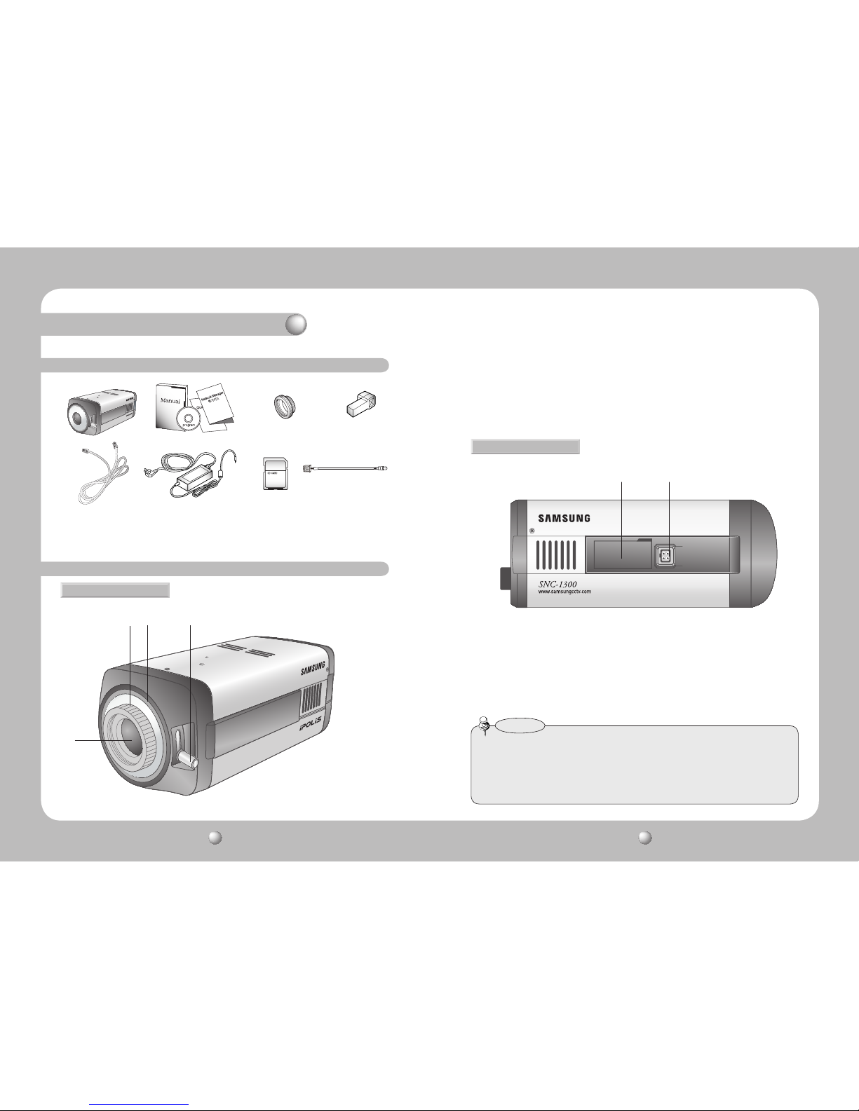
2.1. Package Contents
2.2. Part Names and Functions
❶
Camera Chassis
2
User’s Manual/CD/Quick Guide 3 C-Mount Adapter
❹
Auto Iris Lens Connector Plug ❺ Cross Cable
❻
DC 12V Adapter/Power Cord
7
SD Card (2GB)
8
Included Video Cable
❶ 2
❺ ❻ 7 8
3
❹
❶
Protective Cover : Keep the cover on if the camera is not attached with a lens.
2
C-Mount Lens Adapter : Attach a C-Mount lens here.
3
CS-Mount Lens Adapter : Remove C-Mount lens adapter to attach a CS-Mount lens
directly to the camera.
4
Back Focus Adjustment Lever : Use this lever to adjust the back focus.
5
Auto Iris Lens Connector : Connect an auto iris lens here.
6
SD Memory Card Slot : Insert the SD memory card here.
2.2.1. Front
2.2.2. Side
• The SNC-1300 is compatible only with SD card; MMC cannot be used. Do not insert the SD card
backward; it may damage the slot.
• Only 1 to 2GB SD and 4GB SDHC cards are supported.
• We recommend the FAT32 format.
• Please turn off the camera before removing the SD card; the data may be dama ged otherwise.
Caution
Chapter 2. Product Information
NETWORK CAMERA User Guide
20
NETWORK CAMERA User Guide
21
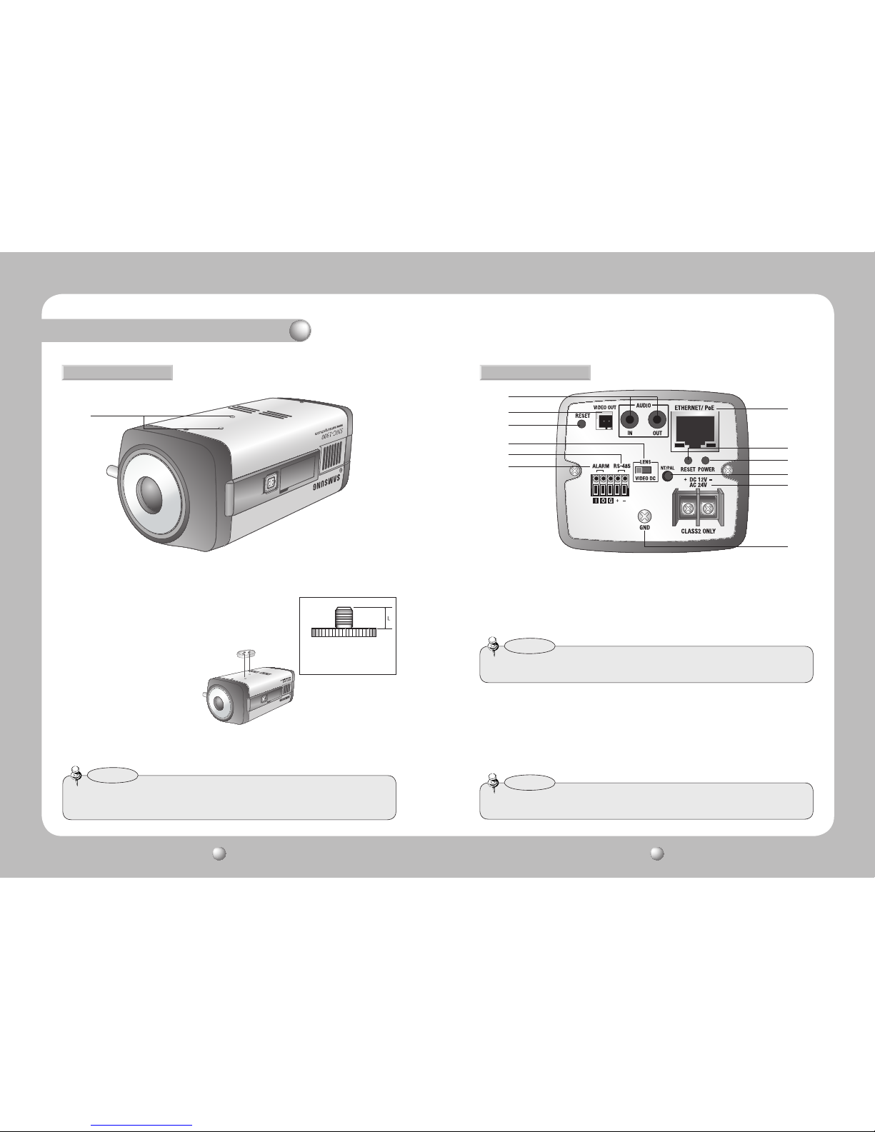
※ The stand fixture can be detached and
attached on the top. When attaching on
the top, use screws less than 5mm in
size. Longer screws may cause critical
errors inside the camera.
7
❿
⓭
⓫
⓬
9
7
Stand Fixture Groove : Use this groove to attach a stand.
Make sure to use the correct-size
screws as shown in the figure on
the right.
1/4˝-20UNC (20 THREAD)
L: 4.5mm±0.2mm (ISO Standard),
or 0.197˝ (ASA Standard)
• A stand is not provided with the camera. When using a stand, please refer to the stand user's manual
as well.
Caution
2.2.3. Bottom 2.2.4. Back
⓮
⓰
⓯
⓱
⓲
⓳
8
Audio Input/Output :
IN : The audio input terminal; connect a sound source such as a mic.
OUT : The audio output terminal; connect a sound receiver such as a speaker.
9
Video Output :
Video output terminal is used to set the focus and other functions when the
camera is installed. (You can optimize your monitor’s screen between NTSC and PAL mode using
the NT/PAL switch.)
Chapter 2. Product Information
❽
• The camera is compatible only with the included video cable.
Caution
❿
RESET Switch : Use this switch to reset the camera to its factory defaults. When pressing the reset
switch for longer than 5 seconds, the RESET LED starts blinking as the camera resets to the
factory defaults. To reset the camera, please wait at least 1 minute after the camera is turned on.
⓫
Auto Iris Lens Switch : Select DC or Video depending on your current auto iris lens type.
⓬
RS-485 : Connect the RS-485 to SRX-100B or SUNGJIN with the plus (+) signal to plus
and minus (-) signal to minus.
• A 30m or shorter length is recommended for the connection.
Caution
NETWORK CAMERA User Guide
22
NETWORK CAMERA User Guide
23
Category Minimum Requirements Recommended Requirements
CPU Intel Core 2 Duo E4300 or better Intel Core 2 Duo E7400 or better
Main Memory 1GB or more 2GB or more
Video Memory 256M or more 512MB or more
Display 1600 X 1200 (w/ 32-bit color) or higher / OpenGL compatible
Hard Disk 80GB or more
Operating System Windows 2000 SP4 / Windows XP Professional / Window Vista
Network 10/100 Base-T Ethernet
DirectX 9.0 or higher
2.3. PC Requirements
⓮
ETHERNET : Connect to a 10/100 Mbps Ethernet network by using a standard RJ-45
connector. You can also use this terminal for PoE (IEEE 802.3af) to supply power to the
camera. The orange LED starts blinking when the camera is successfully connected to a
network and starts transferring data.
⓯
RESET LED :
When pressing the reset switch for longer than 5 seconds, this green LED starts blinking
as the camera resets to its factory defaults.
⓰
POWER LED : This LED turns on when the camera is turned on.
⓱
NT/PAL : Use this switch to optimize your monitor’s screen between NTSC and PAL mode.
⓲
Power : Connect the camera’s default power adapter here.
⓳
GROUND : Use this terminal to ground the camera to external devices.
• Connecting the SNC-1300 network camera to a PoE device may transfer a higher voltage to the
camera; please contact your vender for assistance when installing and uninstalling the camera.
Caution
Chapter 2. Product Information
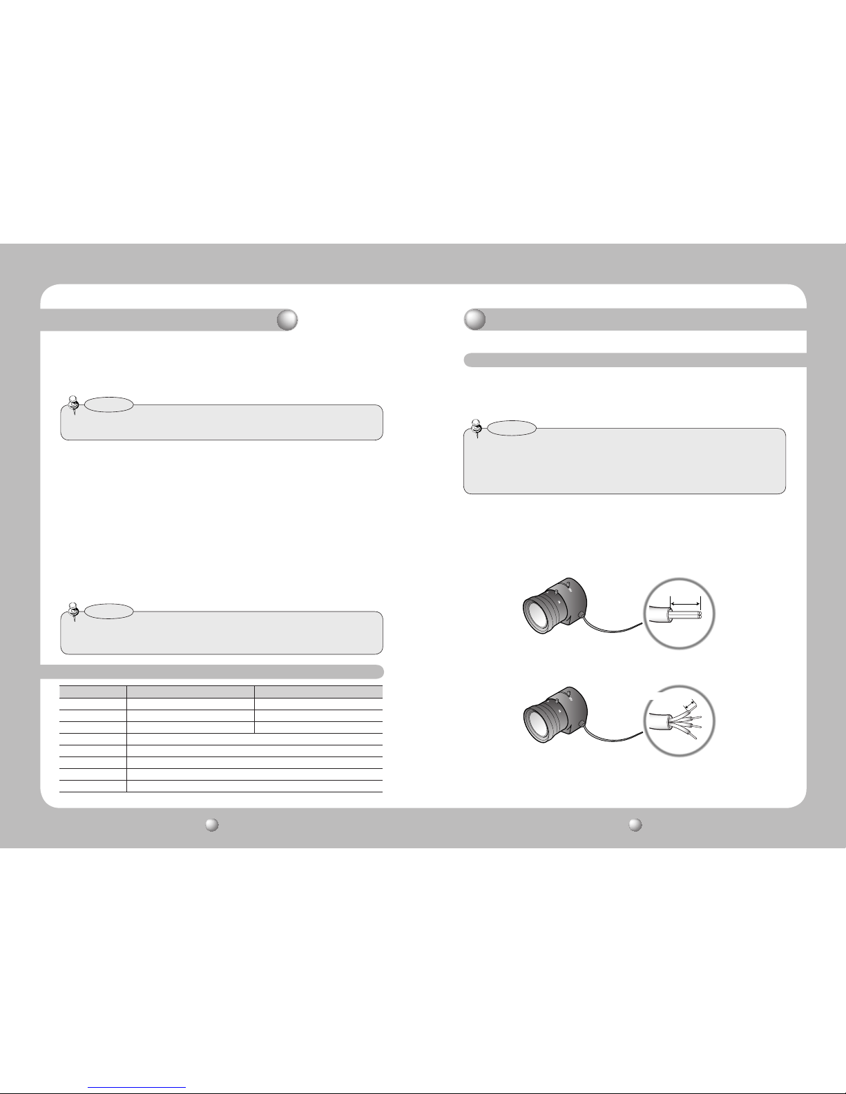
3.1. Installing Lens
Lenses are sold separately; an auto iris lens, CS-mount lens, or C-mount lens can be used
with this product.
• To take full advantage of this product, it is recommended that you use an auto iris lens with DC drive.
• Keep the lens surface free of pollutants such as dirt or fingerprints, since lens contamination causes
degradation in picture quality.
• Lenses other than dedicated megapixel lenses may cause degradation in picture quality.
Caution
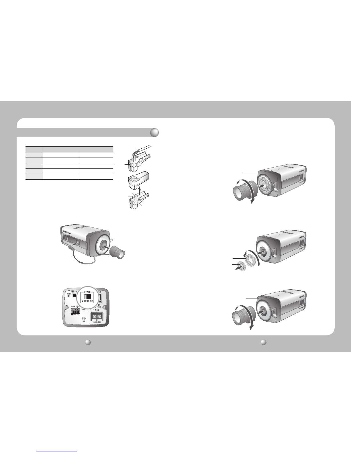
1. Strip the coating from the end of the auto iris lens cable for approximately 8 mm.
2. Strip the coating from the insulated conductor of lens cable for approximately 2mm.
3. Remove the cover from the Auto Iris Lens Connector Plug, and solder the lens cable to the
connector plate of the connector plug.
■
When Using an Auto Iris Lens
Approx. 8mm
Approx. 2mm
(1/16 inch)
Chapter 3. Installing Camera & Network Setup
• Connected length is 30m or less.
Caution
⓭
ALARM :
Alarm Input (I) : Used to connect an alarm input signal such as infrared or thermal sensors.
Alarm Output (O) : Used to connect an alarm output signal such as a flash light or siren.
NETWORK CAMERA User Guide
24
NETWORK CAMERA User Guide
25
SNC-1300
4. Close the cover of the Auto Iris Lens Connector Plug.
Remove the camera's Front Protective Cover, and attach
the auto iris lens to the camera by turning the lens
clockwise.
5. Insert the connector plug of the auto iris lens cable into the
Auto Iris Lens Connector on the side of the camera. (This
product is compatible with the SLA-2882.)
6. Use the Auto Iris Lens Switch on the back of the camera to select DC or VIDEO depending
on the type of your auto iris lens.
Pin 3
Pin 1
Connector
Lens Cable
Pin 4
Pin 2
Lens
Type DC VIDEO
Pin 1 Damping - Red (Power)
Pin 2 Damping + NC
Pin 3 Drive + White (Video Signal)
Pin 4 Drive - Black (Ground)
Chapter 3. Installing Camera & Network Setup
Remove the camera’s Front Protective Cover, and attach the C-Mount lens to the camera by
turning the lens clockwise.
1. Remove the camera’s Front Protective Cover and C-Mount Adapter.
2. Attach the CS-Mount lens by turning the lens clockwise.
■
When Using a C-Mount Lens
■
When Using a CS-Mount Lens
C-Mount Adapter
C-Mount Adapter
CS-Mount Adapter
Protection Cap
NETWORK CAMERA User Guide
26
NETWORK CAMERA User Guide
27
• Please make sure that your lens connector has the dimensions illustra ted below. If you use a lens
whose connector does not fit the camera, you may damage the
camera or fail to attach the lens securely.
• If your lens is too heavy, your camera will be out of balance and may
be damaged. Please use a lens that does not weigh more than 450g
(15.87 oz.)
• The recommended mode for the Automatic Light Control (ALC) for
an auto iris lens is Av Mode. Using Pk mode may cause image
brightness to constantly change.
Caution
C-Mount Lens: 10mm or smaller
CS-Mount Lens: 5mm or smaller
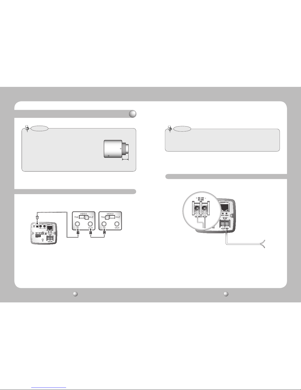
3.2. Connecting Monitor
Connect a cable to the camera’s rear video output terminal and a monitor's video input terminal.
SNC-1300 Network Camera
· The wiring varies depending on your monitor type and peripheral devices; please refer to
the user manual of each device.
· Please keep the monitor and camera turned off while connecting them.
· As shown in the picture above, set the 75Ω/ Hi-Z switch of each device to Hi-Z for the
middle video receiver and to 75Ω for the end device.
• This product is a network camera that transfers video over a network; the video output terminal is used
to set the imaging range of the camera upon the installation.
• Please make sure that the video output terminal of this product is not connected to an y recording
equipment as this can cause problems.
Caution
3.3. Power Input
The SNC-1300 requires an adapter with a voltage of at least AC 24V/1A or DC12V/2A. Make
sure to use an appropriate adapter for the camera.
■
AC/DC Compatible
Chapter 3. Installing Camera & Network Setup
Intermediate
End monitor
 Loading...