

Samsung SNB-6003, SND-6083, SNB-6004, SND-6084, SNB-600 User Manual

NETWORK CAMERA
User Manual
SNB-6003/SNB-6004
SND-6083/SND-6084

Copyright
©2013 Samsung Techwin Co., Ltd. All rights reserved.
Trademark
is the registered logo of Samsung Techwin Co., Ltd.
The name of this product is the registered trademark of Samsung Techwin Co., Ltd.
Other trademarks mentioned in this manual are the registered trademark of their respective company.
Restriction
Samsung Techwin Co., Ltd shall reserve the copyright of this document. Under no circumstances, this document shall
be reproduced, distributed or changed, partially or wholly, without formal authorization of Samsung Techwin.
Disclaimer
Samsung Techwin makes the best to verify the integrity and correctness of the contents in this document, but no
formal guarantee shall be provided. Use of this document and the subsequent results shall be entirely on the user’s own
responsibility. Samsung Techwin reserves the right to change the contents of this document without prior notice.
Design and specifications are subject to change without prior notice.
The default password can be exposed to a hacking thread so it is recommended to change the password
after installing the product.
Note that the security and other related issues caused by the unchanged password shall be responsible
for the user.
Network Camera
User Manual
English _3
● OVERVIEW
IMPORTANT SAFETY INSTRUCTIONS
1. Read these instructions.
2. Keep these instructions.
3. Heed all warnings.
4. Follow all instructions.
5. Do not use this apparatus near water.
6. Clean only with dry cloth.
7. Do not block any ventilation openings, Install in accordance with the manufacturer’s
instructions.
8. Do not install near any heat sources such as radiators, heat registers, stoves, or other
apparatus (including amplifiers) that produce heat.
9. Do not defeat the safety purpose of the polarized or grounding-type plug. A polarized
plug has two blades with one wider than the other. A grounding type plug has two
blades and a third grounding prong. The wide blade or the third prong are provided for
your safety. If the provided plug does not fit into your outlet, consult an electrician for
replacement of the obsolete outlet.
10. Protect the power cord from being walked on or pinched particularly at plugs,
convenience receptacles, and the point where they exit from the apparatus.
11. Only use attachments/ accessories specified by the manufacturer.
12. Use only with the cart, stand, tripod, bracket, or table specified by
the manufacturer, or sold with the apparatus. When a cart is used,
use caution when moving the cart/apparatus combination to avoid
injury from tip-over.
13. Unplug this apparatus during lighting storms or when unused for
long periods of time.
14. Refer all servicing to qualified service personnel. Servicing is required when the
apparatus has been damaged in any way, such as power-supply cord or plug is
damaged, liquid has been spilled or objects have fallen into the apparatus, the apparatus
has been exposed to rain or moisture, does not operate normally, or has been dropped.
overview
overview
4_ overview
WARNING
TO REDUCE THE RISK OF FIRE OR ELECTRIC SHOCK, DO NOT EXPOSE
THIS PRODUCT TO RAIN OR MOISTURE. DO NOT INSERT ANY METALLIC
OBJECT THROUGH THE VENTILATION GRILLS OR OTHER OPENNINGS
ON THE EQUIPMENT.
Apparatus shall not be exposed to dripping or splashing and that no objects
filled with liquids, such as vases, shall be placed on the apparatus.
To prevent injury, this apparatus must be securely attached to the Wall/ceiling
in accordance with the installation instructions.
CAUTION
CAUTION
RISK OF ELECTRIC SHOCK.
DO NOT OPEN
CAUTION
: TO REDUCE THE RISK OF ELECTRIC SHOCK.
DO NOT REMOVE COVER (OR BACK).
NO USER SERVICEABLE PARTS INSIDE.
REFER SERVICING TO QUALIFIED SERVICE PERSONNEL.
EXPLANATION OF GRAPHICAL SYMBOLS
The lightning flash with arrowhead symbol, within an
equilateral triangle, is intended to alert the user to the
presence of “dangerous voltage” within the product’s
enclosure that may be of sufficient magnitude to constitute a
risk of electric shock to persons.
The exclamation point within an equilateral triangle is intended
to alert the user to the presence of important operating
and maintenance (servicing) instructions in the literature
accompanying the product.

English _5
● OVERVIEW
Class construction
An apparatus with CLASS
construction shall be connected to a MAINS
socket outlet with a protective earthing connection.
Battery
Batteries(battery pack or batteries installed) shall not be exposed to excessive
heat such as sunshine, fire or the like.
Disconnection Device
Disconnect the main plug from the apparatus, if it’s defected. And please call
a repair man in your location.
When used outside of the U.S., it may be used HAR code with fittings of
an approved agency is employed.
CAUTION
Risk of explosion if battery is replaced by an incorrect type.
Dispose of used batteries according to the instructions.
These servicing instructions are for use by qualified service personnel only.
To reduce the risk of electric shock do not perform any servicing other than
that contained in the operating instructions unless you are qualified to do so.
The CVBS out terminal of the product is provided for easier installation, and is
not recommended for monitoring purposes.
Please use the input power with just one camera and other devices must not
be connected.
The ITE is to be connected only to PoE networks without routing to the
outside plant.

overview
6_ overview
Please read the following recommended safety precautions carefully.
yDo not place this apparatus on an uneven surface.
yDo not install on a surface where it is exposed to direct sunlight, near
heating equipment or heavy cold area.
yDo not place this apparatus near conductive material.
yDo not attempt to service this apparatus yourself.
yDo not place a glass of water on the product.
yDo not install near any magnetic sources.
yDo not block any ventilation openings.
yDo not place heavy items on the product.
User’s Manual is a guidance book for how to use the products.
The meaning of the symbols are shown below.
yReference : In case of providing information for helping of product’s usages
yNotice : If there’s any possibility to occur any damages for the goods and
human caused by not following the instruction
Please read this manual for the safety before using of goods and keep it in
the safe place.

English _7
● OVERVIEW
CONTENTS
OVERVIEW
3
3 Important Safety Instructions
9 Product Features
10 Recommended PC Specifications
10
Recommended Micro SD/SDHC/
SDXC Memory Card Specifications
11 NAS recommended specs
11 What’s Included
14 At a Glance (SNB-6003)
17 At a Glance (SNB-6004)
20 At a Glance (SND-6083)
23 At a Glance (SND-6084)
INSTALLATION &
CONNECTION
26
26 Mounting the Lens (SNB-6003/
SNB-6004)
28 Installation (SND-6083/SND-
6084)
31 Inserting/Removing a Micro SD
Memory Card
33 Memory Card Information (Not
Included)
34 Connecting with other Device
NETWORK CONNECTION
AND SETUP
41
41 Connecting the Camera Directly
to Local Area Networking
42 Connecting the Camera Directly
to a DHCP Based DSL/Cable
Modem
43 Connecting the Camera Directly
to a PPPoE Modem
44 Connecting the Camera to a
Broadband Router with the
PPPoE/Cable Modem
45 Buttons used in IP Installer
46 Static IP Setup
50 Dynamic IP Setup
51 Port Range Forward (Port
Mapping) Setup
53 Connecting to the Camera from a
Shared Local PC
53 Connecting to the Camera from a
Remote PC via the Internet

overview
8_ overview
SETUP SCREEN
72
72 Setup
72 Video & Audio Setup
97 Network Setup
108 Event Setup
113 NAS (Network Attached Storage)
guide
130 System Setup
APPENDIX
138
138 Specification
143 Product Overview
146 Troubleshooting
148 Open Source Announcement
WEB VIEWER
54
54 Connecting to the Camera
56 Login
57 Installing Silverlight Runtime
60 Installing STW WebViewer Plugin
62 Using the Live Screen
65 Playing the recorded video

English _9
● OVERVIEW
PRODUCT FEATURES
•Full HD Video Quality
•Multi-Streaming
This network camera can display videos in different resolutions and qualities
simultaneously using different CODECs.
•Web Browser-based Monitoring
Using the Internet web browser to display the image in a local network environment.
•Alarm
When an event occurs, video is either sent to the email address registered by the user, sent
to the FTP server, saved in a Micro SD card or NAS, or a signal is sent to the alert output
terminal.
•Tampering Detection
Detects tempering attempts on video monitoring.
•Motion Detection
Detects motion from the camera’s video input.
•Intelligent Video Analysis
Analyzes video to detect logical events of specified conditions from the camera’s video
input.
•Face Detection
Detects faces from the camera’s video input.
•Audio Detection
Detects sound louder than a certain level specified by user.
•Smart Codec
Adaptively applies codecs for a portion of the camera’s field of view to improve the quality
of such area specified by user.
•Auto Detection of Disconnected Network
Detects network disconnection before triggering an event.
•ONVIF Compliance
This product supports ONVIF Profile-S.
For more information, refer to www.onvif.org.

overview
10_ overview
RECOMMENDED PC SPECIFICATIONS
•CPU :
Intel Core 2 Duo 2.4 GHz or higher (for using 1920x1080 30 fps)
Intel Core i7 2.8 GHz or higher (for using 1920x1080 60 fps)
`
Web Plug-in is optimized to SSE 4.1 Instruction Set.
•Resolution : 1280X1024 pixels or higher (32 bit color)
•RAM : 2GB or higher
•Supported OS : Windows XP / VISTA / 7, MAC OS X 10.7
•Supported Browser : Microsoft Internet Explorer (Ver. 10 ~ 7)
Mozilla Firefox (Ver. 19 ~9) ※ Windows Only
Google Chrome (Ver. 25 ~ 15) ※ Windows Only
Apple Safari (Ver. 6.0.2(Mac OS X 10.8, 10.7 only), 5.1.7) ※ Mac OS X only
`
Windows 8 is supported only in the Desktop mode.
`
Neither a beta test version unlike the version released in the company website nor the developer version will
be supported.
`
For IPv6 connection, Window 7 or higher is recommended.
`
For Mac OS X, only the Safari browser is supported.
•Video Memory : 256MB or higher
J
`
If the driver of the video graphic adapter is not installed properly or is not the latest version, the
video may not be played properly.
`
For a multi-monitoring system involving at least 2 monitors, the playback performance can be
deteriorated depending on the system.
RECOMMENDED MICRO SD/SDHC/SDXC MEMORY CARD
SPECIFICATIONS
•Recommended capacity : 4GB ~ 64GB
•For your camera, we recommend you use a memory card from the following
manufacturers:
Micro SD/SDHC/SDXC Memory Card : Sandisk, Transcend
•For the framerate below 30 fps, it is recommended to use the specification memory card
of Class 6 or higher.
•For the framerate over 31 fps, it is recommended to use the specification memory card of
Class 10 UHS or higher.
English _11
● OVERVIEW
NAS RECOMMENDED SPECS
•Recommended capacity : 200GB or higher is recommended.
•Simultaneous access : One unit of NAS can accept a maximum of sixteen camera
accesses.
•For this camera, you are recommended to use a NAS with the following manufacturer’s
specs.
Recommended products Available sizes
Netgear NAS A maximum of 16 cameras can access simultaneously.
Synology NAS A maximum of 16 cameras can access simultaneously.
J
`
When you use Netgear’s NAS equipment, do not allocate the capacity for use.
`
If you use NAS equipment for purposes other than video saving, the number of accessible
cameras may be reduced.
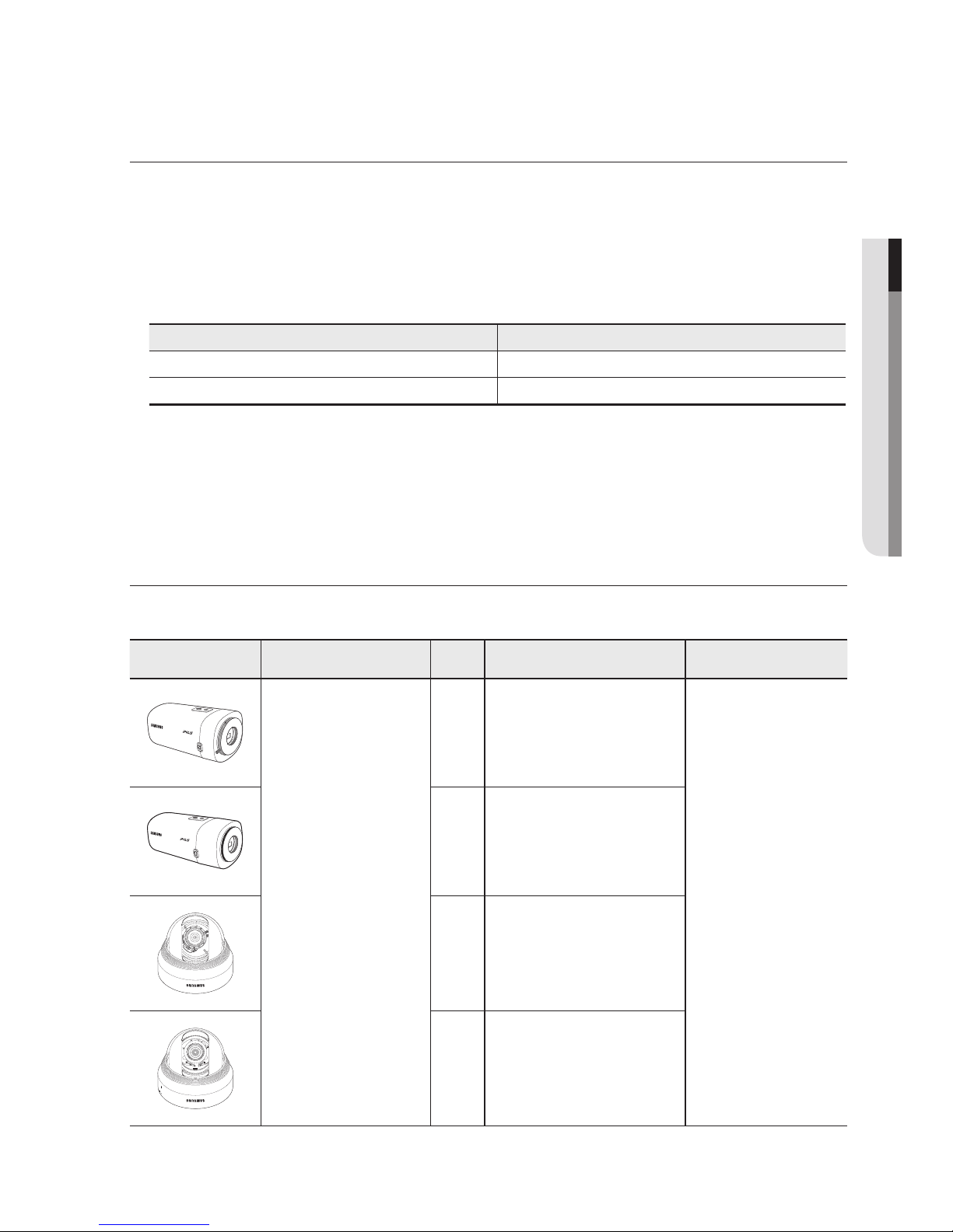
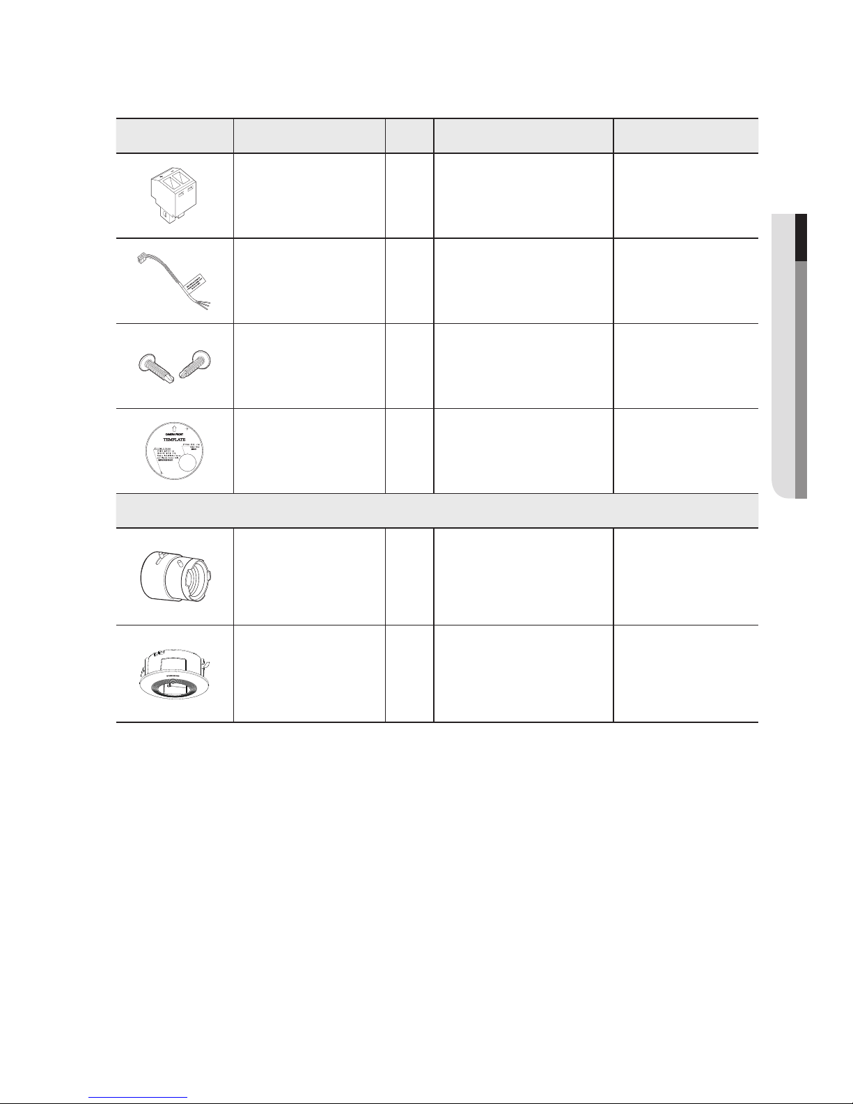
WHAT’S INCLUDED
Please check if your camera and accessories are all included in the product package.
Appearance Item Name
Quantity
Description Model Name
Camera
1
SNB-6003 or
SNB-6004 or
SND-6083 or
SND-6084
1
1
1
overview
12_ overview
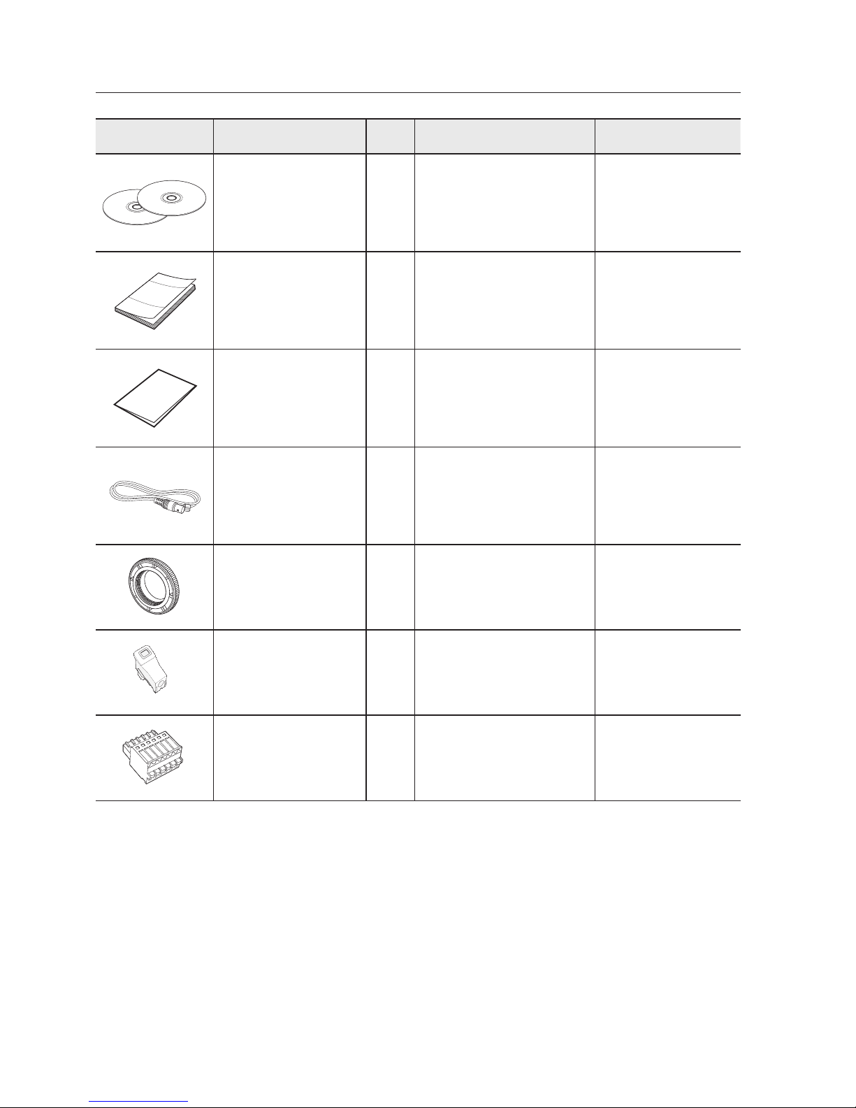
Appearance Item Name
Quantity
Description Model Name
Instruction book,
Installer S/W CD,
CMS S/W DVD
2
SNB-6003/
SNB-6004/
SND-6083/
SND-6084
Quick Guide
(Optional)
1
SNB-6003/
SNB-6004/
SND-6083/
SND-6084
Warranty card
(Optional)
1
SNB-6003/
SNB-6004/
SND-6083/
SND-6084
Cable for the testing
monitor
1
Used to test the camera
connection to a portable display
device
SNB-6003/
SNB-6004/
SND-6083/
SND-6084
C Mount Adapter 1
Used to install the C Mount
camera lens
SNB-6003/
SNB-6004
Automatic Iris Lens
Connector
1
Useful for camera lens
installation
SNB-6003/
SNB-6004
6-position Terminal Block 1 Used for alarm in/out terminals
SNB-6003/
SNB-6004
English _13
● OVERVIEW
Appearance Item Name
Quantity
Description Model Name
Power Terminal Block 1 Plugged in the power plug
SND-6083/
SND-6084
Alarm Cable 1 Useful for alarm connection
SND-6083/
SND-6084
Screw 2
Useful for installation on the
ceiling, wall, etc.
SND-6083/
SND-6084
Template
1
Product installation guide
SND-6083/
SND-6084
Options (not included)
CS/C Lens
Optional lens to be inserted in
a camera
SNB-6003/
SNB-6004
Indoor Buried Housing
Housing for installing indoor
buried type cameras
SND-6083/
SND-6084
overview
14_ overview
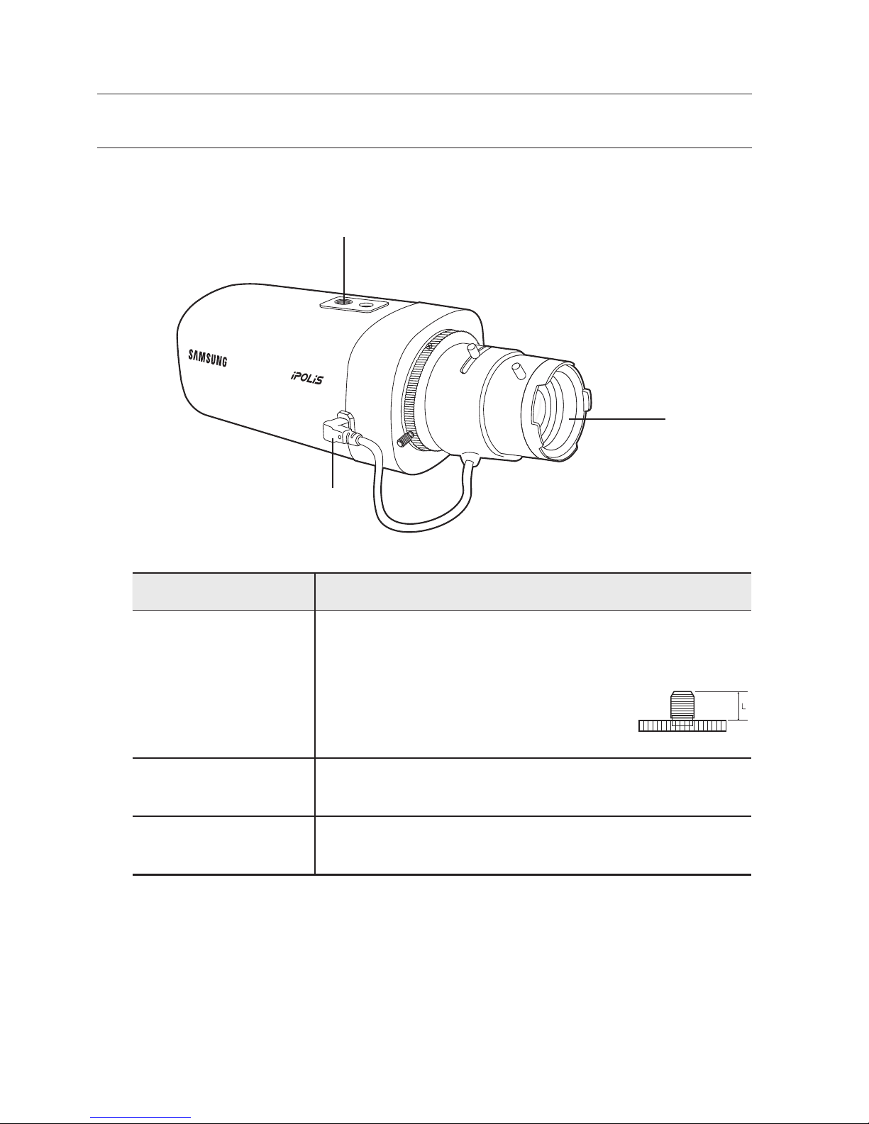
AT A GLANCE (SNB-6003)
Front Side
Item Description
a
Mounting Bracket
Screw Hole
Used to fix the camera on a mounting bracket.
`
The screw size : It is the specification for the screws used to fasten the
camera to the support.
1/4" - 20 UNC
L : 4.5mm±0.2mm (ISO Standard) or 0.197" (ASA
Standard)
b
Auto Iris Lens
(Optional)
Installed on the lens adaptor.
c
Auto Iris Lens
Connector
Used to supply power and output signal to control the iris of the lens.
M
`
Wipe out a dirty surface of the lens softly with a lens tissue or cloth to which you have applied
ethanol.
`
Mounting Bracket is not included.
For more information to use mounting bracket, refer to the product’s documentation.
a
b
c
English _15
● OVERVIEW
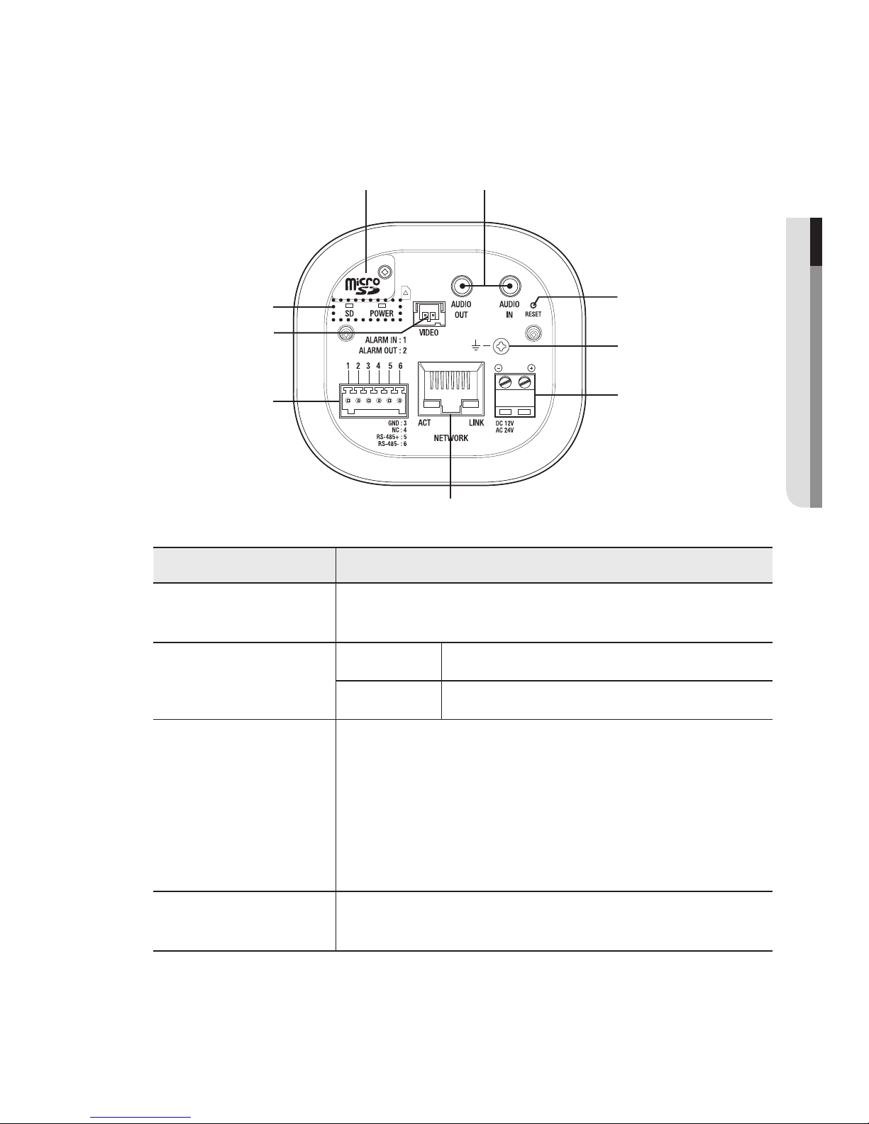
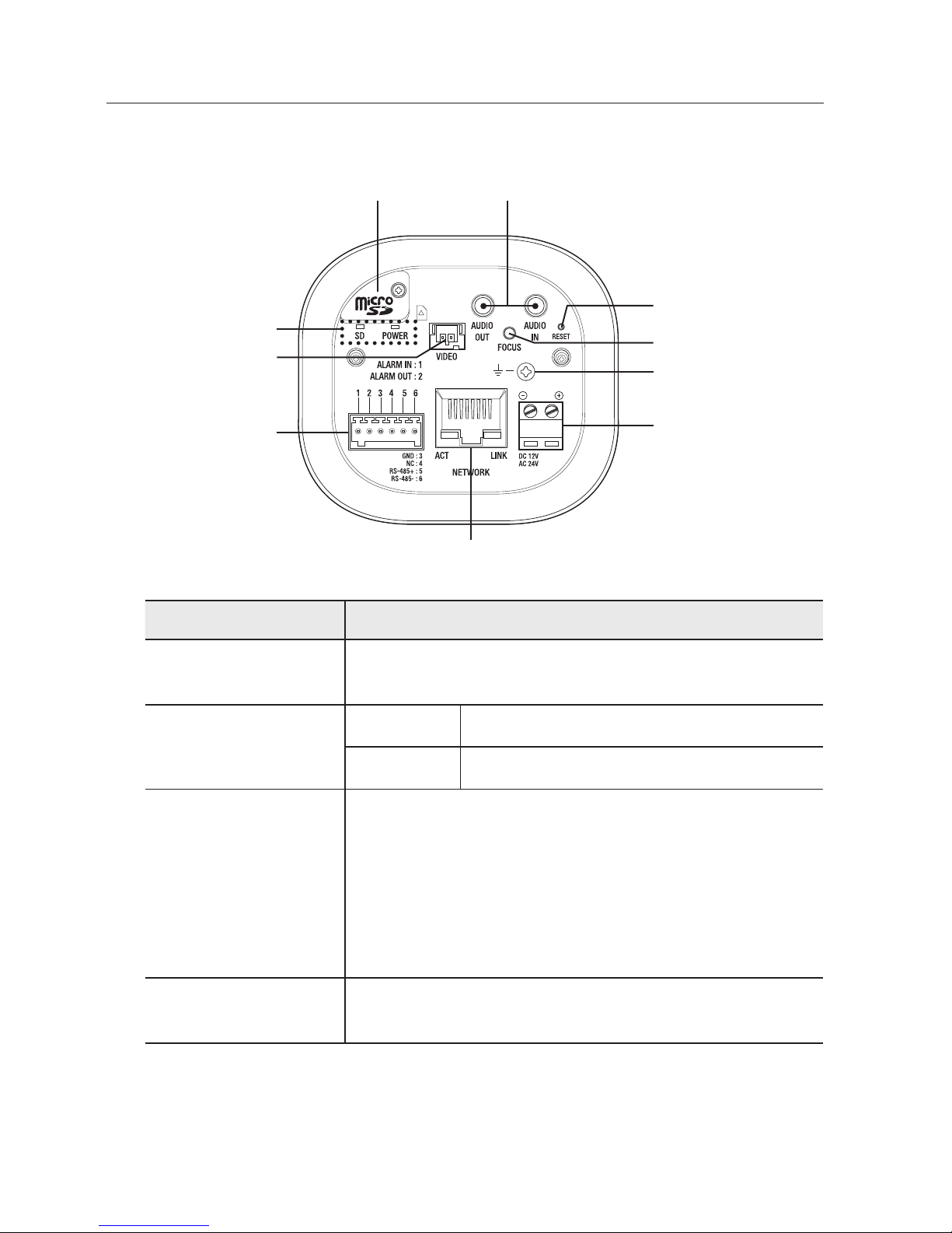
Rear Side
Item Description
a
Micro SD Memory
Card Compartment
Compartment for the
Micro SD memory card.
b
Audio terminal
AUDIO OUT Used to connect to speakers.
AUDIO IN Used to connect to a microphone.
c
Reset Button
The button restores all camera settings to the factory default.
Press and hold for about 5 seconds to reboot the system.
J
If you reset the camera, the network settings will be adjusted so that
DHCP can be enabled. If there is no DHCP server in the network, you
must run the IP Installer program to change the basic network settings
such as IP address, Subnet mask, Gateway, etc., before you can
connect to the network.
d
Lightning protective
grounding port
Used to discharge the lightning current safely outside in order to protect the
camera.
a b
c
e
f
g
i
d
h

overview
16_ overview
Item Description
e
Power Port Used to plug the power cable.
f
Network Port Used to connect the PoE or Ethernet cable for network connection.
g
Alarm I/O Port
ALARM IN
Used to connect the alarm input sensor or external day/
night sensor.
ALARM OUT Used to connect the alarm output signal.
GND Used for earth-grounding.
RS-485+ RS-485 Data line
RS-485- RS-485 Data line
h
Test Monitor Out
Output port for test monitoring the video output. Use the test monitor cable
to connect to a mobile display and check the test video.
i
SD, Power Indicators
SD
ON : A memory card is inserted and operates normally.
Flashing : Failed to record, insufficient space, or inserted
abnormally.
OFF : Camera is off, camera is restarting, memory card is
not in place, or when record is off.
POWER
ON : While the power is on
OFF : If the power is off
J
`
RS-485 port only supports direct connection with pan/tilt driver and external connections of the
RS-485 controller is not supported.
English _17
● OVERVIEW
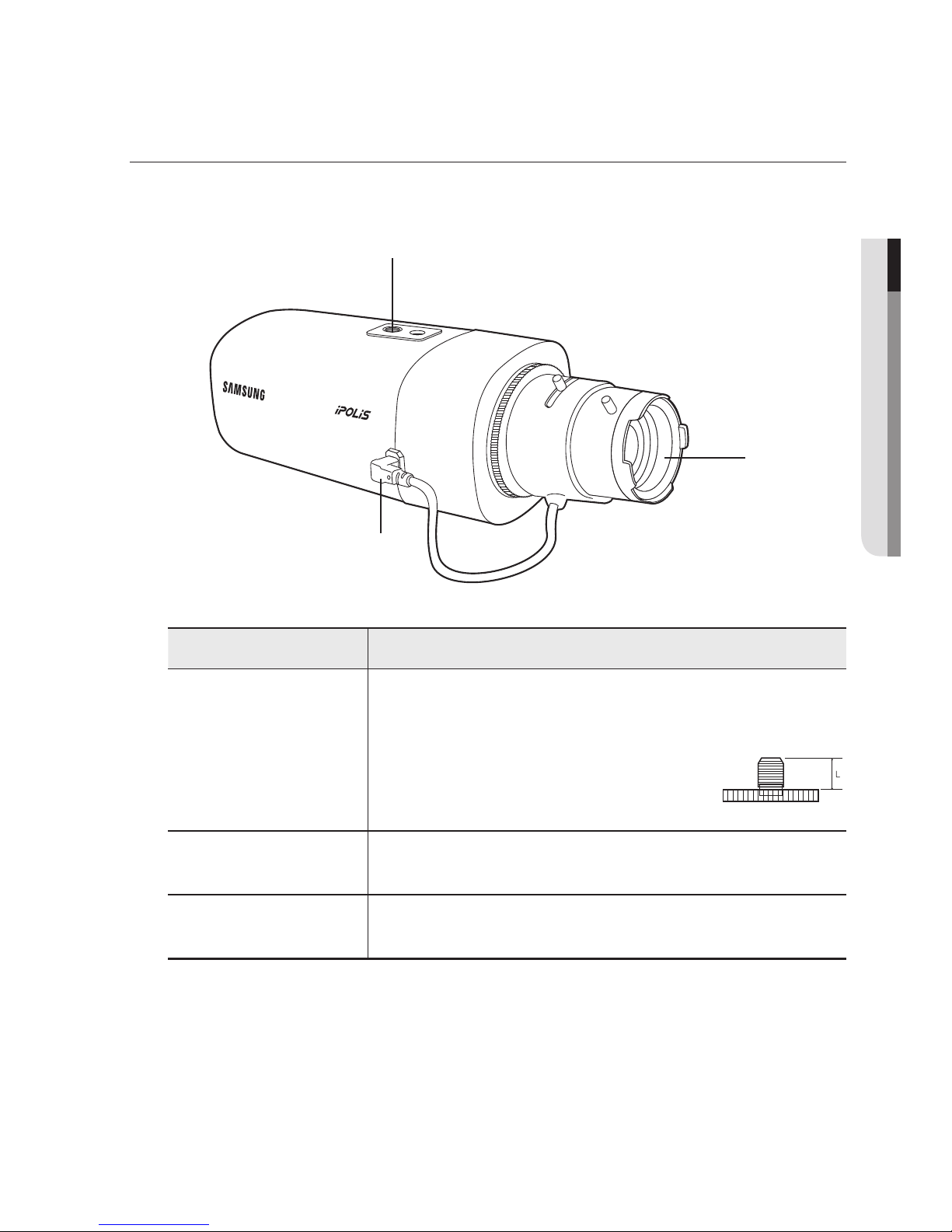
AT A GLANCE (SNB-6004)
Front Side
Item Description
a
Mounting Bracket
Screw Hole
Used to fix the camera on a mounting bracket.
`
The screw size : It is the specification for the screws used to fasten the
camera to the support.
1/4" - 20 UNC
L : 4.5mm±0.2mm (ISO Standard) or 0.197" (ASA
Standard)
b
Auto Iris Lens
(Optional)
Installed on the lens adaptor.
c
Auto Iris Lens
Connector
Used to supply power and output signal to control the iris of the lens.
M
`
Wipe out a dirty surface of the lens softly with a lens tissue or cloth to which you have applied
ethanol.
`
Mounting Bracket is not included.
For more information to use mounting bracket, refer to the product’s documentation.
a
b
c
overview
18_ overview
Rear Side
Item Description
a
Micro SD Memory
Card Compartment
Compartment for the
Micro SD memory card.
b
Audio terminal
AUDIO OUT Used to connect to speakers.
AUDIO IN Used to connect to a microphone.
c
Reset Button
The button restores all camera settings to the factory default.
Press and hold for about 5 seconds to reboot the system.
J
If you reset the camera, the network settings will be adjusted so that
DHCP can be enabled. If there is no DHCP server in the network, you
must run the IP Installer program to change the basic network settings
such as IP address, Subnet mask, Gateway, etc., before you can
connect to the network.
d
Focus Adjustment
Button
The button adjusts the focus of image automatically.
a b
c
f
g
h
j
e
i
d

English _19
● OVERVIEW
Item Description
e
Lightning protective
grounding port
Used to discharge the lightning current safely outside in order to protect the
camera.
f
Power Port Used to plug the power cable.
g
Network Port Used to connect the PoE or Ethernet cable for network connection.
h
Alarm I/O Port
ALARM IN
Used to connect the alarm input sensor or external day/
night sensor.
ALARM OUT Used to connect the alarm output signal.
GND Used for earth-grounding.
RS-485+ RS-485 Data line
RS-485- RS-485 Data line
i
Test Monitor Out
Output port for test monitoring the video output. Use the test monitor cable
to connect to a mobile display and check the test video.
j
SD, Power Indicators
SD
ON : A memory card is inserted and operates normally.
Flashing : Failed to record, insufficient space, or inserted
abnormally.
OFF : Camera is off, camera is restarting, memory card is
not in place, or when record is off.
POWER
ON : While the power is on
OFF : If the power is off
J
`
RS-485 port only supports direct connection with pan/tilt driver and external connections of the
RS-485 controller is not supported.
overview
20_ overview
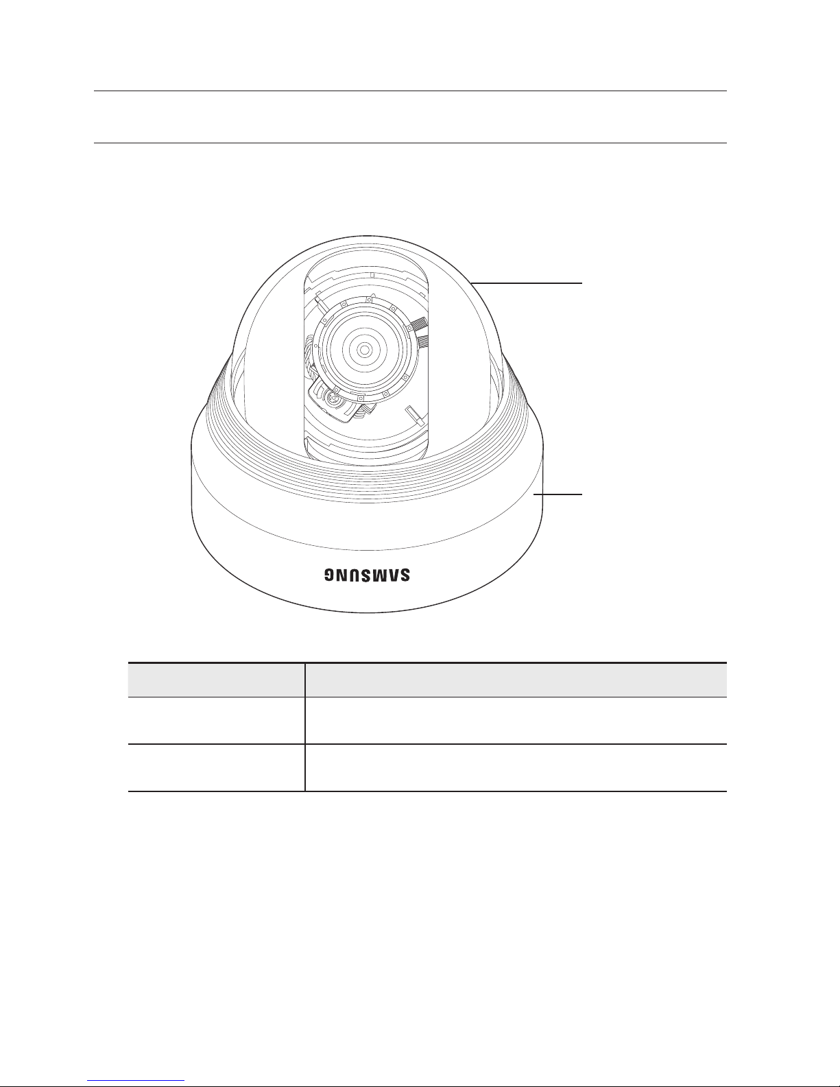
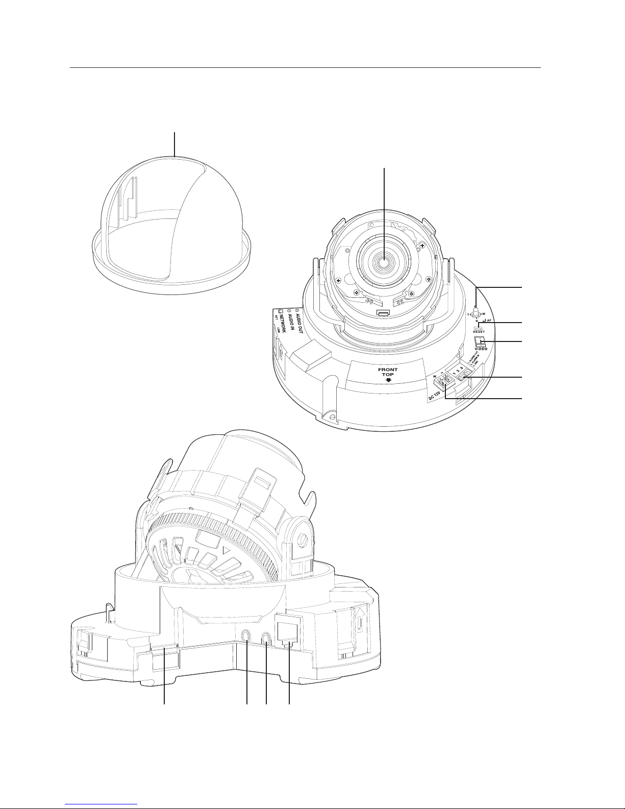
AT A GLANCE (SND-6083)
Appearance
Item Description
a
Dome cover
Case cover used to protect the lens and the main unit.
b
Camera Case
Housing part that covers the camera body.
a
b
English _21
● OVERVIEW
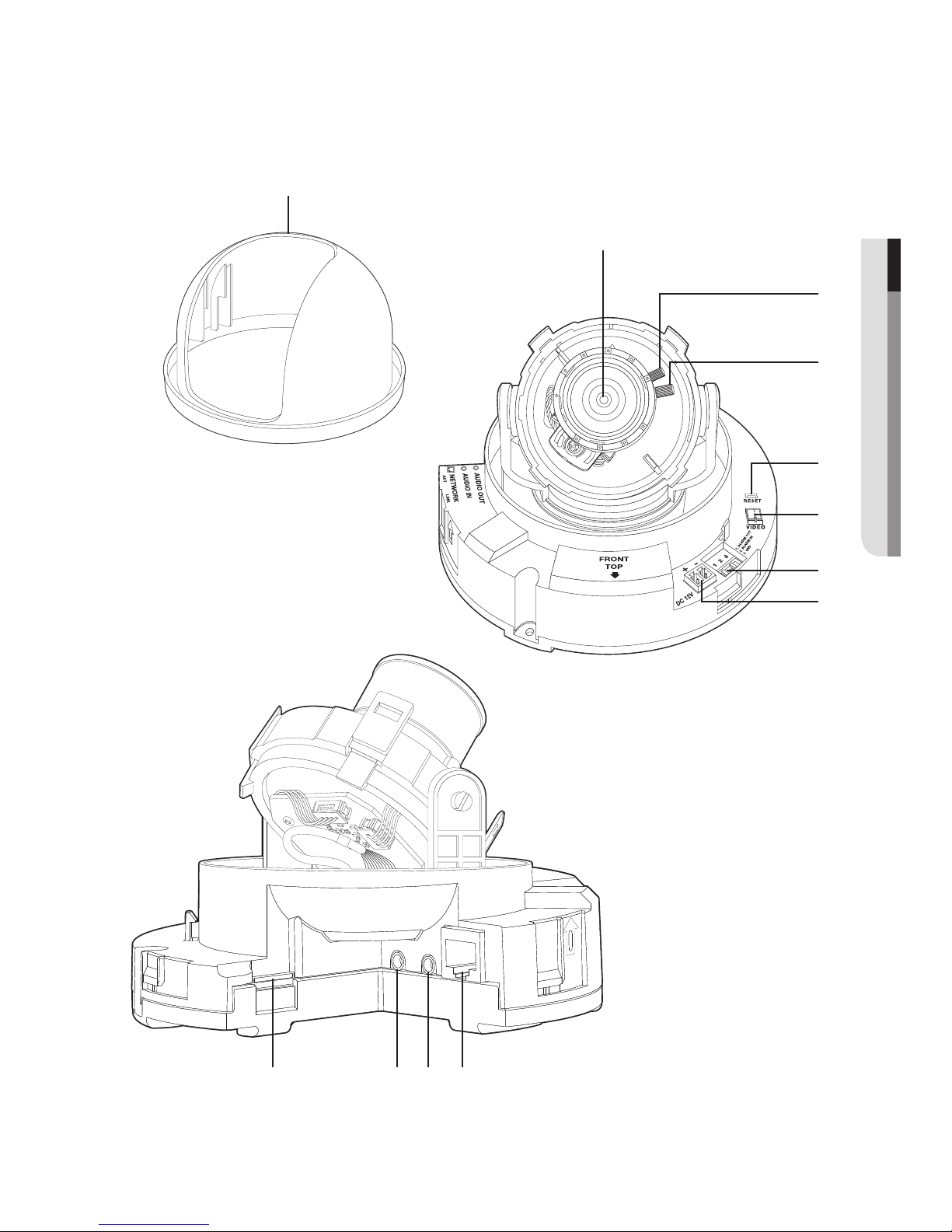
Components
b
c
d
h
e
f
g
a
AUDIO
IN
AUDIO
OUT
AUDIO
IN
AUDIO
OUT
jk li

overview
22_ overview
Item Description
a
Internal Cover It is a cover to protect the main body.
b
Lens
Lens for the camera.
c
Focus Adjusting
Lever
Turn it left and right to adjust the lens focus and rotate it clockwise to fix it.
d
Zoom Adjusting
Lever
It can be used to adjust or fix the lens zoom.
e
Reset Button
The button restores all camera settings to the factory default.
Press and hold for about 5 seconds to reboot the system.
J
If you reset the camera, the network settings will be adjusted so that
DHCP can be enabled. If there is no DHCP server in the network, you
must run the IP Installer program to change the basic network settings
such as IP address, Subnet mask, Gateway, etc., before you can
connect to the network.
f
Test Monitor Out
Output port for test monitoring the video output. Use the test monitor cable
to connect to a mobile display and check the test video.
g
Alarm I/O Port
ALARM IN
Used to connect the alarm input sensor or external day/
night sensor.
ALARM OUT Used to connect the alarm output signal.
GND Used for earth-grounding.
h
Power Port Used to plug the power cable.
i
Micro SD Memory
Card Compartment
Compartment for the
Micro SD memory card.
j
Audio Out Jack Used to connect to speakers.
k
Audio In Jack Used to connect to a microphone.
l
Network Port Used to connect the PoE or Ethernet cable for network connection.
English _23
● OVERVIEW
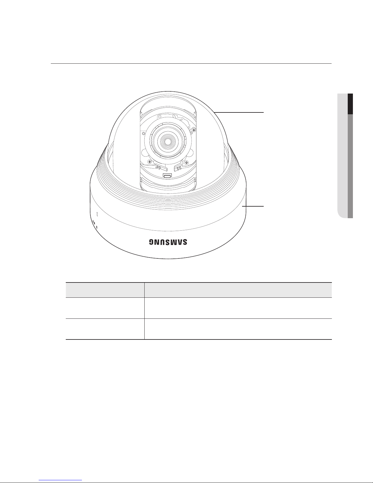
AT A GLANCE (SND-6084)
Appearance
Item Description
a
Dome cover
Case cover used to protect the lens and the main unit.
b
Camera Case
Housing part that covers the camera body.
a
b
overview
24_ overview
Components
c
b
g
d
e
f
a
AUDIO
IN
AUDIO
OUT
ij kh

English _25
● OVERVIEW
Item Description
a
Internal Cover It is a cover to protect the main body.
b
Lens
Lens for the camera.
c
Zoom/Focus Control
Button
T Zoom in (Tele)
W Zoom out (Wide)
N Focusing on a near object (Near)
F Focusing on a far object (Far)
Focus Control Press this button for automatic focus control.
d
Reset Button
The button restores all camera settings to the factory default.
Press and hold for about 5 seconds to reboot the system.
J
If you reset the camera, the network settings will be adjusted so that
DHCP can be enabled. If there is no DHCP server in the network, you
must run the IP Installer program to change the basic network settings
such as IP address, Subnet mask, Gateway, etc., before you can
connect to the network.
e
Test Monitor Out
Output port for test monitoring the video output. Use the test monitor cable
to connect to a mobile display and check the test video.
f
Alarm I/O Port
ALARM IN
Used to connect the alarm input sensor or external day/
night sensor.
ALARM OUT Used to connect the alarm output signal.
GND Used for earth-grounding.
g
Power Port Used to plug the power cable.
h
Micro SD Memory
Card Compartment
Compartment for the
Micro SD memory card.
i
Audio Out Jack Used to connect to speakers.
j
Audio In Jack Used to connect to a microphone.
k
Network Port Used to connect the PoE or Ethernet cable for network connection.
26_ installation & connection
installation & connection
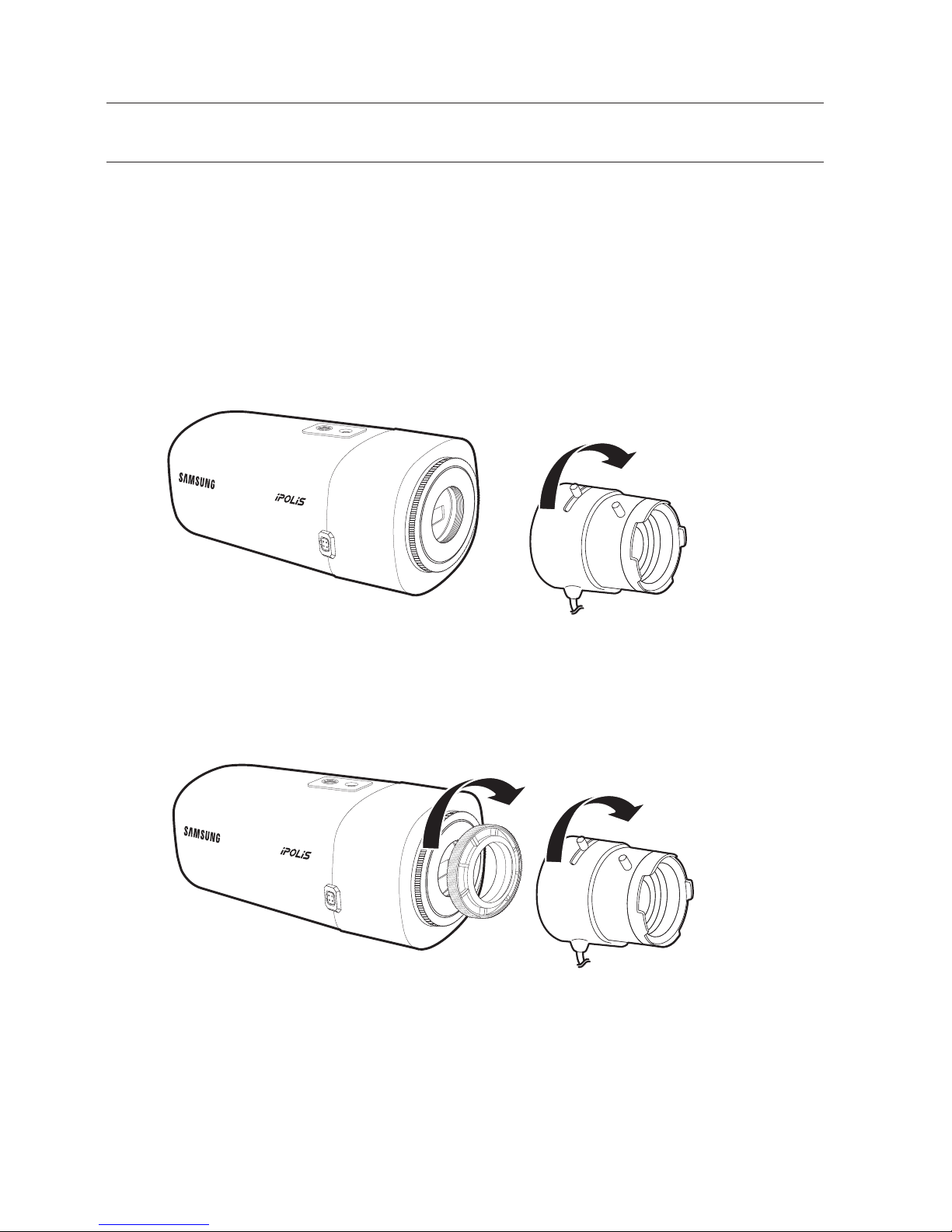
MOUNTING THE LENS (SNB-6003/SNB-6004)
Disconnect the power before proceeding.
M
`
The C lens and CS lens are not included in the product package.
It is recommended that megapixel lens are use on this camera to optimise performance.
Mounting the CS lens on a camera
Turn the CS lens clockwise to attach it.
Mounting the C lens on a camera
Turn the C mount adapter included in the product package clockwise and turn the C lens
clockwise.
CS Lens
C Lens
English _27
● INSTALLATION & CONNECTION
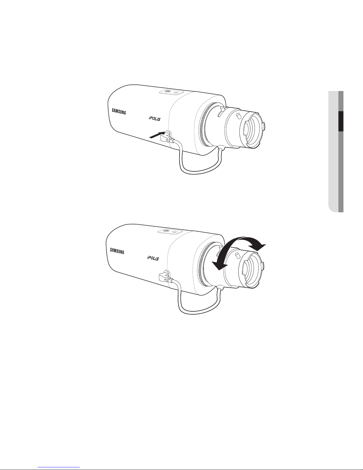
Connecting the Auto Iris Lens connector
Plug the iris connector of the lens in the camera connecting groove.
Focusing
Select a target to film, turn the zoom lever of the lens to adjust the magnification and then
focus the lens so that target is clearly displayed.
M
`
After focusing with the zoom lever of the lens, press the [FOCUS] button on the rear of the camera
to adjust the lens even more clearly. (It is applicable only to the SNB-6004 model.)
installation & connection
28_ installation & connection
INSTALLATION (SND-6083/SND-6084)
Precautions before installation
Ensure you read out the following instructions before installing the camera:
•It must be installed on the area (ceiling or wall) that can withstand 5 times the weight
of the camera including the installation bracket.
•Stuck-in or peeled-off cables can cause damage to the product or a fire.
•For safety purposes, keep anyone else away from the installation site.
And put aside personal belongings from the site, just in case.
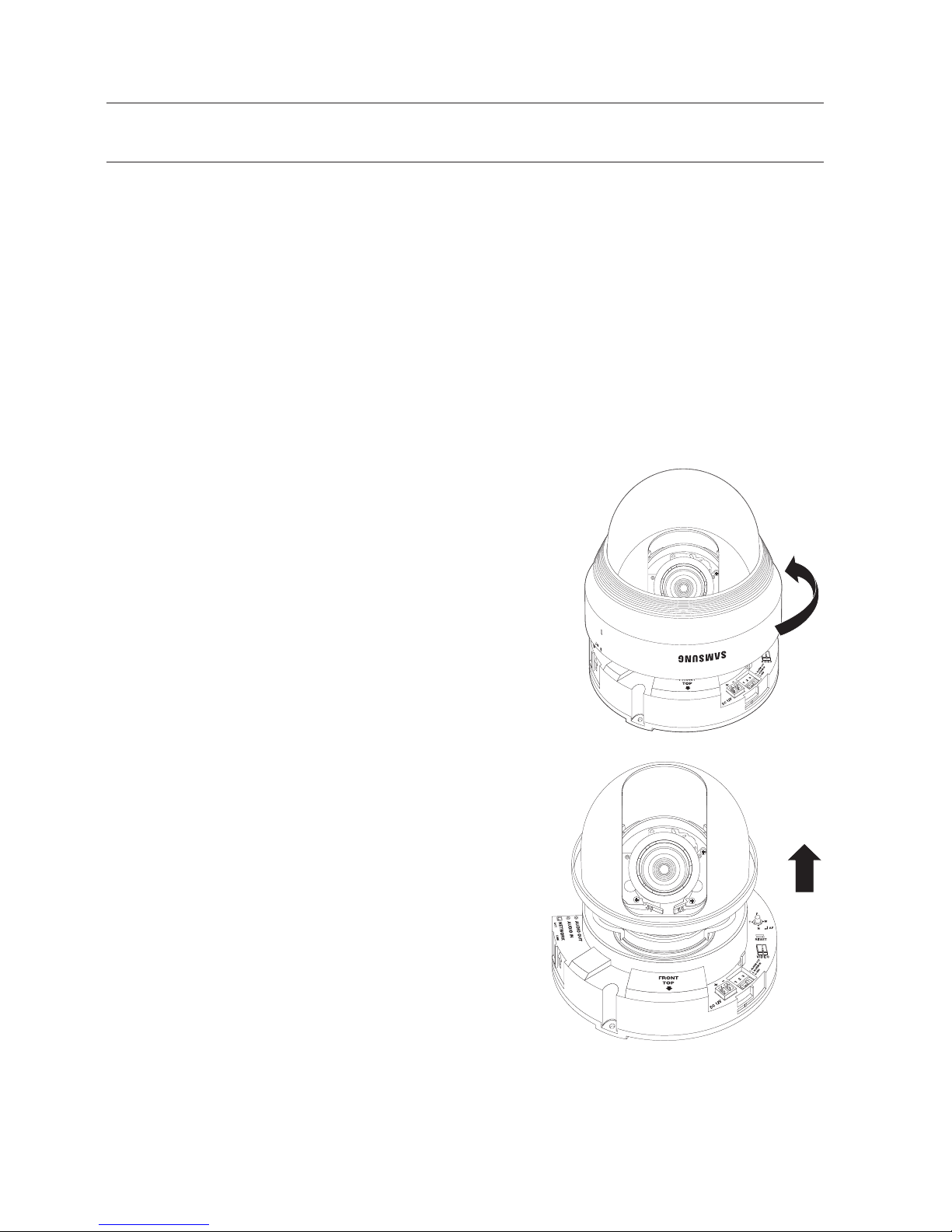
Disassembling
1. Use one hand to hold the camera’s bottom part
and turn the cover counterclockwise with another
hand to separate it.
2. Lift up the inner cover to separate it.
English _29
● INSTALLATION & CONNECTION
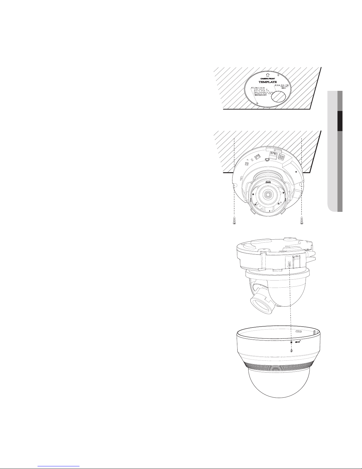
Installation
1. Attach the installation template to the
selected area and punch 3 holes as shown in
the figure.
2. Use the 2 supplied screws to fix the camera
to the 2 punched holes.
`
Set the <FRONT TOP> mark imprinted on the
camera to face the direction of camera monitoring.
3. Connect the camera internal terminal with the
corresponding cable.
4.
Refer to “Adjusting the monitoring direction
for the camera” to adjust the lens in a desired
direction. (page 30)
5. Fasten the dome case (dome cover + camera
case) to the main body as shown in the figure.
J
`
Pay attention to the direction for assembly.
FRONT
TOP
DC 12V
1 2 3
1. ALARM OUT
2. ALARM IN
3. GND
VIDEO
RESET
T
F
W
N
AF
+
-
installation & connection
30_ installation & connection
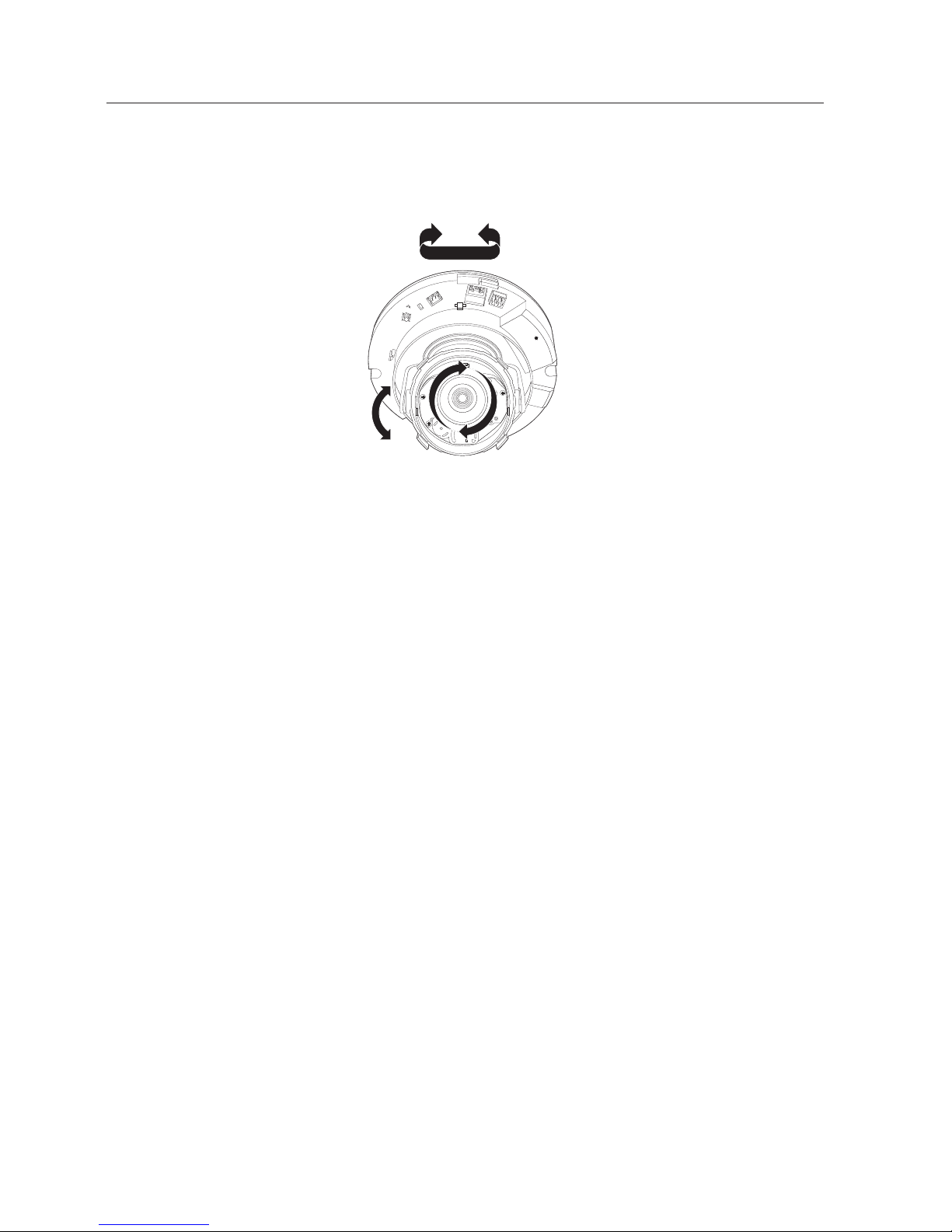
Adjusting the monitoring direction for the camera (SND-6083/
SND-6084)
`Adjusting the monitoring direction
You can adjust the camera direction only when the camera is fixed on the ceiling.
Where, rotating the camera unit to the left or right is called Pan, adjusting the tilt is called
Tilt, and turning the lens on its axis is called Rotation.
- The effective range of pan is a total of 35
4 degrees.
- The effective range of rotation is a total of 355 degrees.
- The effective range of tilt is a total of
67 degrees.
J
`
The image can be covered up by the camera case depending on the angle.
`
Do not forcefully turn the focus/zoom lens after the dome case is disassembled.
Otherwise, it may cause an incorrect focus due to a motor failure.
`Methods of adjustment
1. After installing the camera, adjust the panning angle in consideration of the
monitoring direction.
2. Set the horizontal angle so that the image is not reversed.
`In case of the SND-6083 model, rotate the lens using the rib around the lens unit.
In case of the SND-6084 model, rotate the lens with the cover on the rear of the lens unit.
3. Adjust the tilt angle so that the camera faces toward the monitoring object.
FRONT
TOP
DC 12V
1 2 3
1. ALARM OUT
2. ALARM IN
3. GND
VIDEO
RESET
T
F
W
N
AF
+
-
Pan
Tilt
Lens rotation
 Loading...