


NETWORK CAMERA
User Manual
SNB-2000(P)
2_ overview
CAUTION
RISK OF ELECTRIC SHOCK.
DO NOT OPEN
CAUTION
:
TO REDUCE THE RISK OF ELECTRIC SHOCK, DO NOT REMOVE COVER (OR BACK) NO USER
SERVICEABLE PARTS INSIDE. REFER SERVICING TO QUALIFIED SERVICE PERSONNEL.
This symbol indicates that dangerous voltage consisting a
risk of electric shock is present within this unit.
This symbol indicates that there are important
operating and maintenance instructions in the literature
accompanying this unit.
WARNING
To reduce the risk of fi re or electric shock, do not expose this appliance
to rain or moisture.
To prevent injury, this apparatus must be securely attached to the fl oor/
wall in accordance with the installation instructions.
If this power supply is used at 24V ac, a suitable plug adapter should be
used.
The camera is to be only connected to PoE networks without routing to
the outside plant.
WARNING
Be sure to use only the standard adapter that is specifi ed in the
specifi cation sheet.
Using any other adapter could cause fi re, electrical shock, or damage to
the product.
Incorrectly connecting the power supply or replacing battery may cause
explosion, fi re, electric shock, or damage to the product.
Do not connect multiple cameras to a single adapter. Exceeding the
capacity may cause abnormal heat generation or fi re.
Securely plug the power cord into the power receptacle. Insecure
connection may cause fi re.
y
y
y
y
1.
2
.
3.
4.
overview

English _3
● OVERVIEW
When installing the camera, fasten it securely and fi rmly. The fall of
camera may cause personal injury.
Do not place conductive objects (e.g. screwdrivers, coins, metal parts,
etc.) or containers fi lled with water on top of the camera. Doing so may
cause personal injury due to fi re, electric shock, or falling objects.
Do not install the unit in humid, dusty, or sooty locations. Doing so may
cause fi re or electric shock.
If any unusual smells or smoke come from the unit, stop using the
product. In such case, immediately disconnect the power source and
contact the service center. Continued use in such a condition may
cause fi re or electric shock.
If this product fails to operate normally, contact the nearest service
center. Never disassemble or modify this product in any way.
(SAMSUNG is not liable for problems caused by unauthorized
modifi cations or attempted repair.)
When cleaning, do not spray water directly onto parts of the product.
Doing so may cause fi re or electric shock
Do not expose the product to the direct airfl ow from an air conditioner.
Otherwise, it may cause moisture condensation inside the Clear Dome
due to temperature difference between internal and external of the
dome camera.
If you install this product in a low-temp area such as inside a cold store,
you must seal up the wiring pipe with silicon, so that the external air can
not fl ow inside the housing.
Otherwise, external high, humid air may fl ow inside the housing, pooling
moisture or vapor inside the product due to a difference between
internal and external temperature.
5.
6.
7.
8.
9.
10.
11.
12.

overview
4_ overview
CAUTION
Do not drop objects on the product or apply strong blows to it. Keep
away from a location subject to excessive vibration or magnetic
interference.
Do not install in a location subject to high temperature (over 50°C), low
temperature (below -10°C), or high humidity. Doing so may cause fi re or
electric shock.
If you want to relocate the already installed product, be sure to turn off
the power and then move or reinstall it.
Remove the power plug from the outlet when there is a lighting storm.
Neglecting to do so may cause fi re or damage to the product.
Keep out of direct sunlight and heat radiation sources. It may cause fi re.
Install it in a place with good ventilation.
Avoid aiming the camera directly towards extremely bright objects such
as sun, as this may damage the CCD image sensor.
Apparatus shall not be exposed to dripping or splashing and no objects
fi lled with liquids, such as vases, shall be placed on the apparatus.
The Mains plug is used as a disconnect device and shall stay readily
operable at any time.
When using the camera outdoors, moisture may occur inside the
camera due to temperature difference between indoors and outdoors.
For this reason, it is recommended to install the camera indoors. For
outdoor use, use the camera with built-in fan and heater.
1.
2.
3.
4.
5.
6.
7.
8.
9.
10.

English _5
● OVERVIEW
FCC STATEMENT
This device complies with part 15 of the FCC Rules. Operation is subject to the
following two conditions :
1) This device may not cause harmful interference, and
2) This device must accept any interference received including interference that
may cause undesired operation.
CAUTION
This equipment has been tested and found to comply with the limits for a Class A
digital device, pursuant to part 15 of FCC Rules. These limits are designed to provide
reasonable protection against harmful interference when the equipment is operated in a
commercial environment.
This equipment generates, uses, and can radiate radio frequency energy and, if not
installed and used in accordance with the instruction manual, may cause harmful
interference to radio communications. Operation of this equipment in a residential area
is likely to cause harmful interference in which case the user will be required to correct
the interference at his own expense.
IC Compliance Notice
This Class A digital apparatus meets all requirements of the
Canadian Interference.-Causing Equipment Regulations of
ICES-003.

overview
6_ overview
IMPORTANT SAFETY INSTRUCTIONS
Read these instructions.
Keep these instructions.
Heed all warnings.
Follow all instructions.
Do not use this apparatus near water.
Clean only with dry cloth.
Do not block any ventilation openings. Install in accordance with the manufacturer’s
instructions.
Do not install near any heat sources such as radiators, heat registers, or other apparatus
(including amplifi ers) that produce heat.
Do not defeat the safety purpose of the polarized or grounding-type plug.
A polarized plug has two blades with one wider than the other. A grounding type plug
has two blades and a third grounding prong. The wide blade or the third prong is
provided for your safety. If the provided plug does not fi t into your outlet, consult an
electrician for replacement of the obsolete outlet.
Protect the power cord from being walked on or pinched particularly at plugs,
convenience receptacles, and the point where they exit from the apparatus.
Only use attachments/accessories specifi ed by the manufacturer.
Use only with the cart, stand, tripod, bracket, or table specifi ed by
the manufacturer, or sold with the apparatus. When a cart is used,
use caution when moving the cart/apparatus combination to avoid
injury from tip-over.
Unplug this apparatus during lightning storms or when unused for
long periods of time.
Refer all servicing to qualifi ed service personnel. Servicing is required when the
apparatus has been damaged in any way, such as powersupply cord or plug is
damaged, liquid has been spilled or objects have fallen into the apparatus, the apparatus
has been exposed to rain or moisture, does not operate normally, or has been dropped.
Apparatus shall not be exposed to dripping or splashing and no objects
filled with liquids, such as vases, shall be placed on the apparatus
1.
2.
3.
4.
5.
6.
7.
8.
9.
10.
11.
12.
13.
14.

English _7
● OVERVIEW
CONTENTS
OVERVIEW
2
6 Important Safety Instructions
9 Product Features
9 Recommended PC Specifi cations
10 What’s Included
11 At a Glance
INSTALLATION &
CONNECTION
13
13 Mounting the lens
15 Connecting with other Device
CAMERA SETUP
17
17
How to use the Keyboard Controller
18 Main Menu
18 Profi le
19 Camera Setup
23 Privacy Zone
24 Others
25 System Info
NETWORK CONNECTION
AND SETUP
26
26 Connecting the Camera to an
Broadband Router with the
xDSL/cable Modem
27 Connecting the Camera to an
Broadband Router with Local
Area Networking
28
Connecting the Camera Directly to
a DHCP-based xDSL/cable Modem
29 Connecting the Camera Directly
to Local Area Networking
30 IP Address Setup
31 Static IP Setup
34 Dynamic IP Setup
35 Port Range Forward (Port
Mapping) Setup
35 Connecting to the camera from a
shared local PC
36 Connecting to the camera from a
remote PC via the Internet

overview
8_ overview
WEB VIEWER
37
37 Connecting to the camera
38 Login
39 Installing ActiveX
40 Using the Live Screen
41 Backup
SETUP SCREEN
43
43 Accessing the Setup screen
44 Default Setup
48 System Setup
51 Overlay Setup
52 Event Setup
58 Network Setup
APPENDIX
59
59 Profi le
60 Terminology
61 Specifi cations
65 Frame Rate (NTSC)
71 Frame Rate (PAL)
77 Troubleshooting
79 GPL/LGPL Software License

English _9
● OVERVIEW
PRODUCT FEATURES
Support various communication protocols
Supports TCP/IP, UDP, RTP/RTSP, SMTP for email, and FTP protocols as well as various
internet protocols such as ARP, HTTP, HTTPS and DHCP.
Web Browser-based Monitoring
Using the Internet web browser to display the image in a local network environment.
Automatic Local IP Setup
Even a network novice can install it with minimum operations.
Alarm
If the camera equipped with an alarm sensor senses any motion, it will send a notifi cation
to a user FTP/email account (SMTP) or send the corresponding signal to the Alarm Out
terminal.
Motion Detection
If the camera with a specifi ed motion area detects a motion in that area, it will send a
notifi cation to a user FTP/email account (SMTP) or send the corresponding signal to the Alarm
Out terminal.
ONVIF (Spec 1.01) Compliance
This product supports ONVIF Core Spec. 1. 01.
For more information, refer to www.onvif.org.
RECOMMENDED PC SPECIFICATIONS
CPU : Pentium4 / 2.4GHz or higher
Operating System : Windows XP(Service Pack2, Service Pack3) / Windows Vista / Windows 7
Resolution : 1024X768 pixels or higher
RAM : 512MB or higher
Web Browser : Internet Explorer 6.0 or higher
Video Card : Radeon, Nvidia
Video Memory : 128MB
DirectX 8.1 or higher
Compatible Broadband Router
Linksys
D-Link
Netgear
Compatible PoE Switches
Linksys SRW224G4P
D-Link DES-1316
SMC SMCPWR-INJ3
y
y
y
y
y
y
y
y
y
y
y
y
y
y
y
y
y
y
y
y

overview
10_ overview
WHAT’S INCLUDED
Please check if your camera and accessories are all included in the product package.
Camera
C Mount Adapter
Auto Iris Lens Connector
Camera Holder (Mount)
& Screws (2EA)
User Manual,
Installer S/W CD,CMS S/W DVD
Quick Guide
Lens Options
CS Lens C Lens
English _11
● OVERVIEW
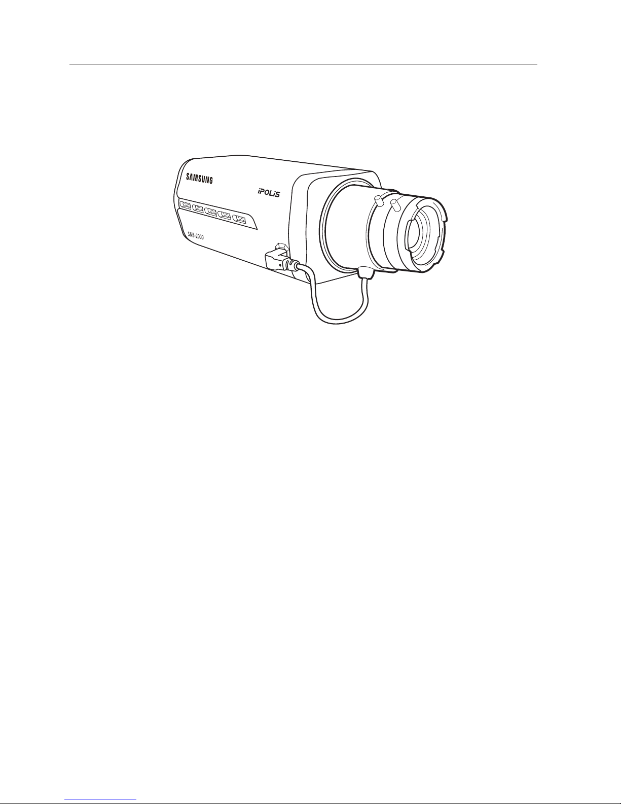
AT A GLANCE
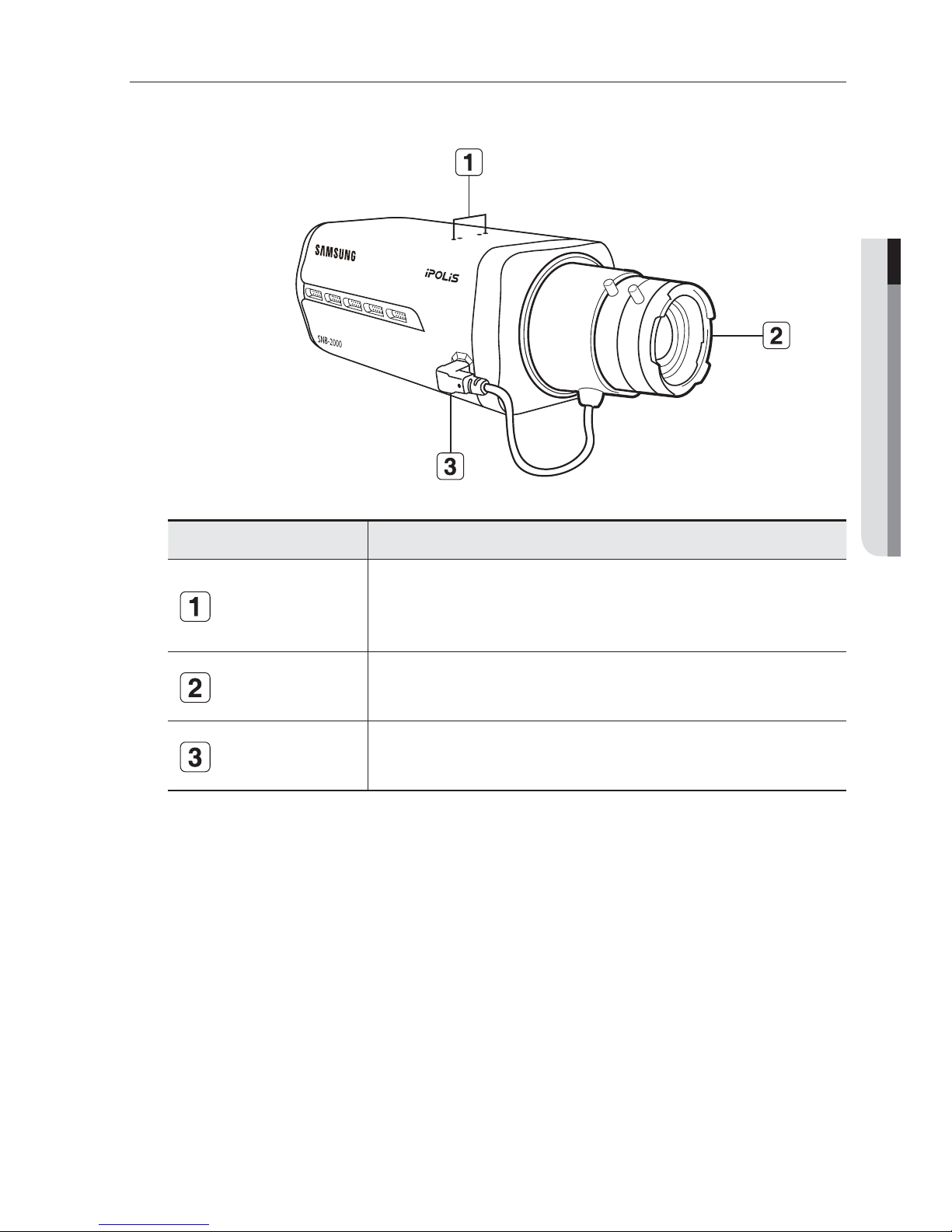
Front Side
Item Description
Camera Holder
(Mount) Holes
Used when you mount the camera onto the bracket by fixing the camera
holder (mount) adaptor with the bracket.
Auto Iris Lens
(Optional)
Installed on the lens adaptor.
Auto Iris Lens
Connector
Used to supply power and output signal to control the iris of the lens.
Wipe out a dirty surface of the lens softly with a lens tissue or cloth to which you have applied
ethanol.
M
overview
12_ overview
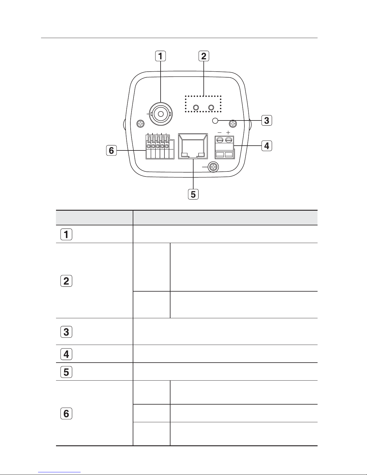
Rear Side
Item Description
Video Out Port Video signal output port connected to the monitor.
System, Power
Indicators
SYSTEM
ON: The camera is turned on and connected to the network
properly.
Blinking: During DDNS setup, or in case of setup failure, or
in a state of unstable network connection
OFF: When the system is rebooting, or turned off
POWER
ON: While the power is on
OFF: If the power is off
Reset Button
Resets the camera settings to the default. Press and hold it for about 3
seconds to turn off the system indicator and restart the system.
Power Port Used to plug the power cable.
Network Port Used to connect to the Network cable.
I/O Port
ALARM IN
1,2
Used to connect the alarm input signal.
GND Used for earth-grounding.
ALARM OUT
1,2
Used to connect the alarm output signal.
SYSTEM POWER
RESET
NETWORK
GND
1 2 3 4 5
VIDEO
AC 24V
LINK
ACT
DC 12V
1,2 : ALARM IN 1,2
3 : GND
4,5 : ALARM OUT 1,2
English _13
● INSTALLATION & CONNECTION
installation & connection
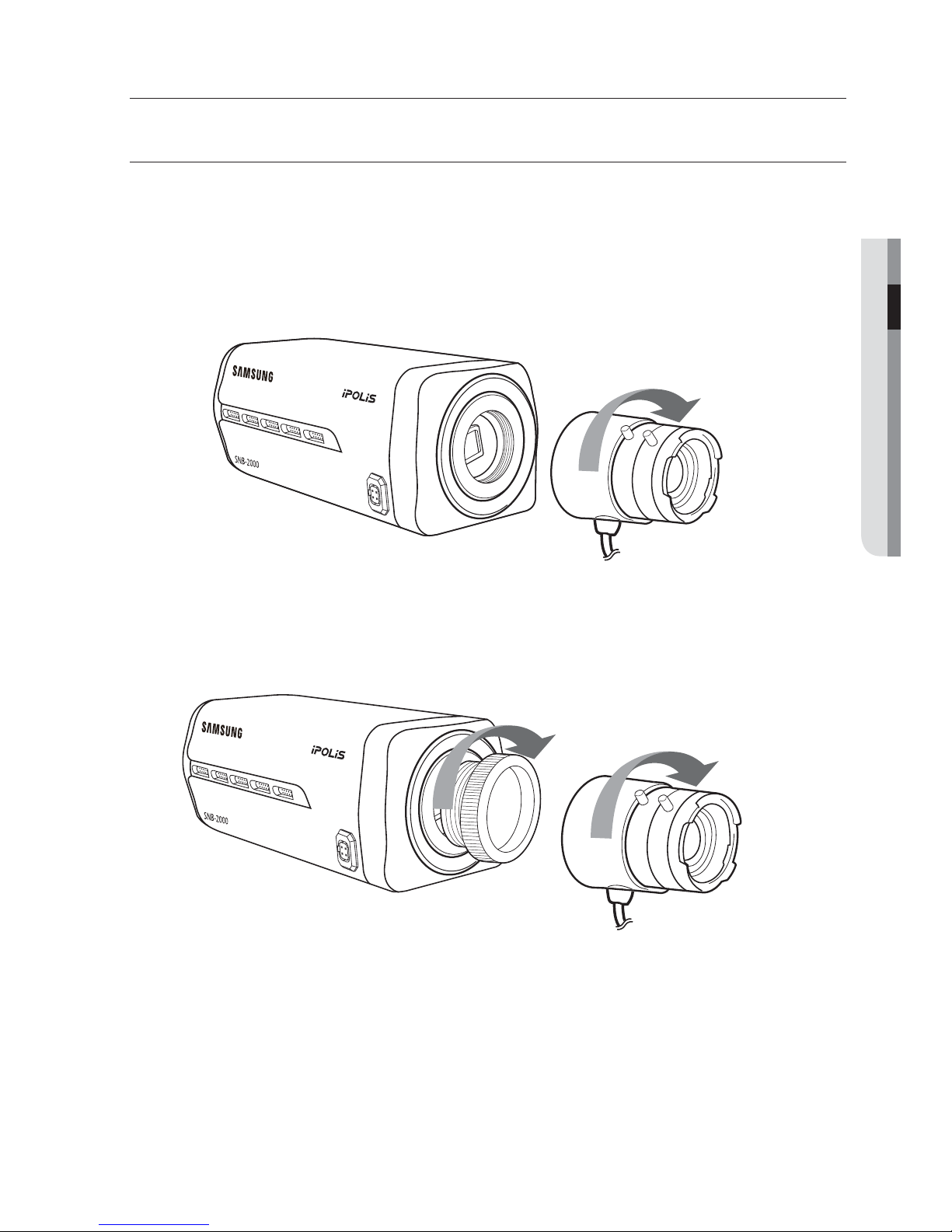
MOUNTING THE LENS
Disconnect the power before proceeding.
Mounting the CS lens
Turn the optional CS lens clockwise to insert it.
Mounting the C lens
Turn the C mount adaptor clockwise to insert it and do the same with the C lens.
CS Lens
C Lens
installation & connection
14_ installation & connection
Connecting the Auto Iris Lens connector
Insert the lens connector into the corresponding hole of the camera.
Focusing
Turn the lens left or right to control the zoom and focus the lens so that you can view a clear,
sharp object.
English _15
● INSTALLATION & CONNECTION
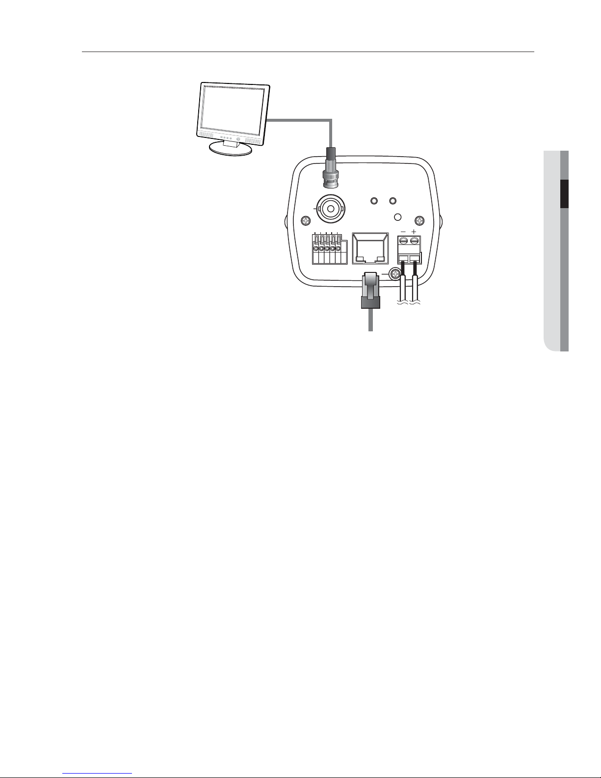
CONNECTING WITH OTHER DEVICE
Connecting to the monitor
Connect the [VIDEO] port of the camera to the video input port of the monitor.
Network Connection
Connect the Network cable to the local network or to the Internet.
Power Supply
Use the screwdriver to connect each line of the power cable to the corresponding port of
the camera.
Be careful not to reverse the polarity when you connect the power cable.
You can also use a router featuring PoE (Power over Ethernet) to supply power to the camera.
J
Monitor
Network
Power
SYSTEM POWER
RESET
NETWORK
GND
1 2 3 4 5
VIDEO
AC 24V
LINK
ACT
DC 12V
1,2 : ALARM IN 1,2
3 : GND
4,5 : ALARM OUT 1,2
installation & connection
16_ installation & connection
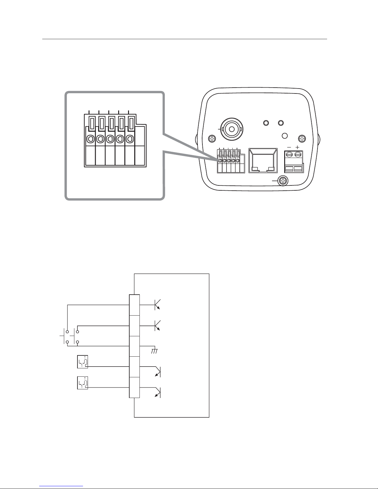
Connecting to the I/O port box
Connect the Alarm I/O signal to the corresponding port of the rear port box.
ALARM IN 1, 2 : Used to connect the alarm input signal.
GND : Used for earth-grounding.
ALARM OUT 1, 2 : Used to connect the alarm output signal.
Alarm I/O Wiring Diagram
y
y
y
1
ALARM IN 1
ALARM OUT 1
ALARM OUT 2
ALARM IN 2
GND
2
3
4
5
External Relay
External Relay
SYSTEM POWER
RESET
NETWORK
GND
1 2 3 4 5
VIDEO
AC 24V
LINK
ACT
DC 12V
1,2 : ALARM IN 1,2
3 : GND
4,5 : ALARM OUT 1,2
1 2 3 4 5
1,2 : ALARM IN 1,2
3 : GND
4,5 : ALARM OUT 1,2
English _17
● CAMERA SETUP
camera setup
You can configure the camera settings using the Web Viewer.
For accessing the Web Viewer, refer to "Network Connection and Setup". (page 26)
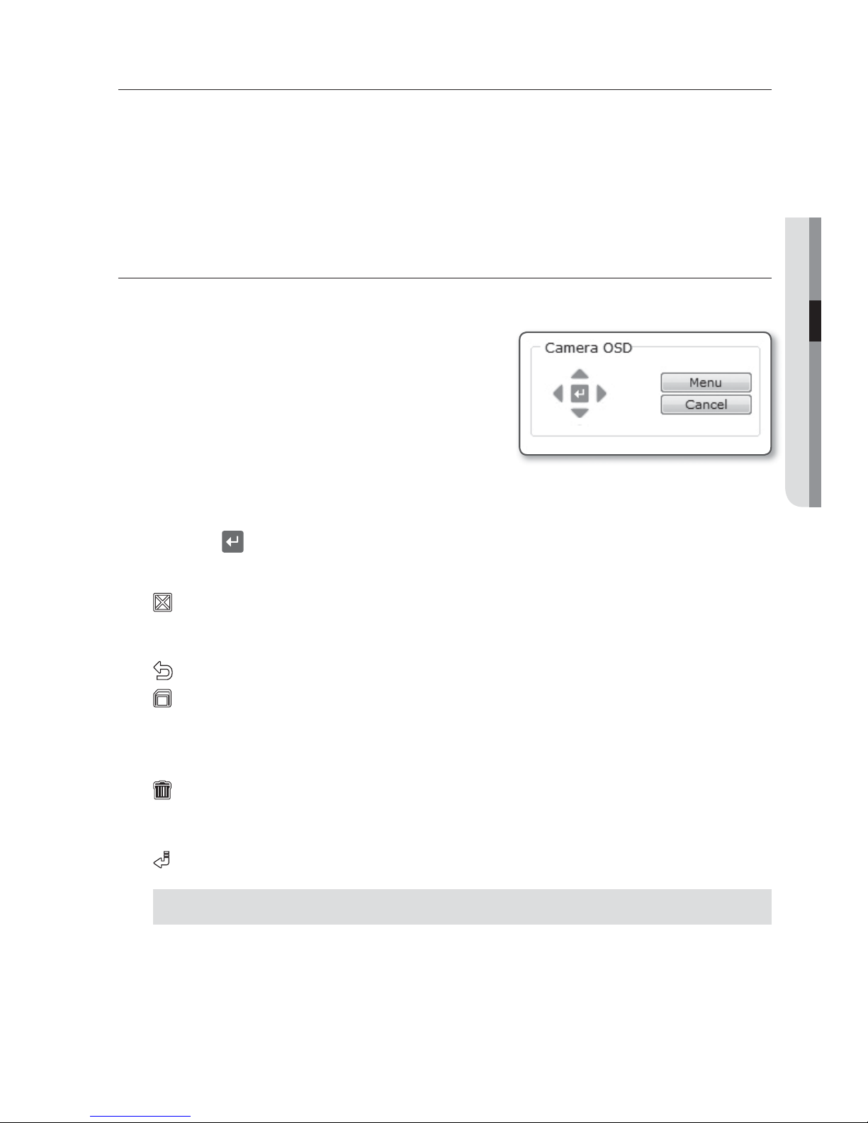
HOW TO USE THE KEYBOARD CONTROLLER
Follow the steps below if you run the Web Viewer for setting the menus.
Launch the Web Viewer.
From the [Camera OSD] menu in the left
pane, click [Menu].
The <MAIN MENU> screen appears.
Click the Up/Down (
▲▼
) buttons to move to a
desired item.
Click
the four direction (
▲▼◄ ►
) buttons to navigate through the menu items.
To change the value of a selected item, click the Left/Right (
◄ ►
) buttons.
Click [
].
Your changes will be applied.
: Exits the menu setup screen.
Before exiting the setup screen, select [SAVE] to save your settings, or [QUIT] to
cancel them.
: Saves your settings and returns to the previous screen.
: Use this icon if you want to save your settings after you specified the mask area and
privacy area, etc.
Once you saved your settings, the changes remain intact even if you select [QUIT] on
exit.
: Use this icon if you want to delete a mask, or privacy area, etc.
Once you deleted your settings, the deletions remain valid even if you select [QUIT] on
exit.
: This arrow appears next to a menu that contains sub items.
For the items with the "*" mark on the right, You can get help from "Terminology". (page 60)
M
1.
2.
3.
4.
5.
6.
18_ camera setup
camera setup
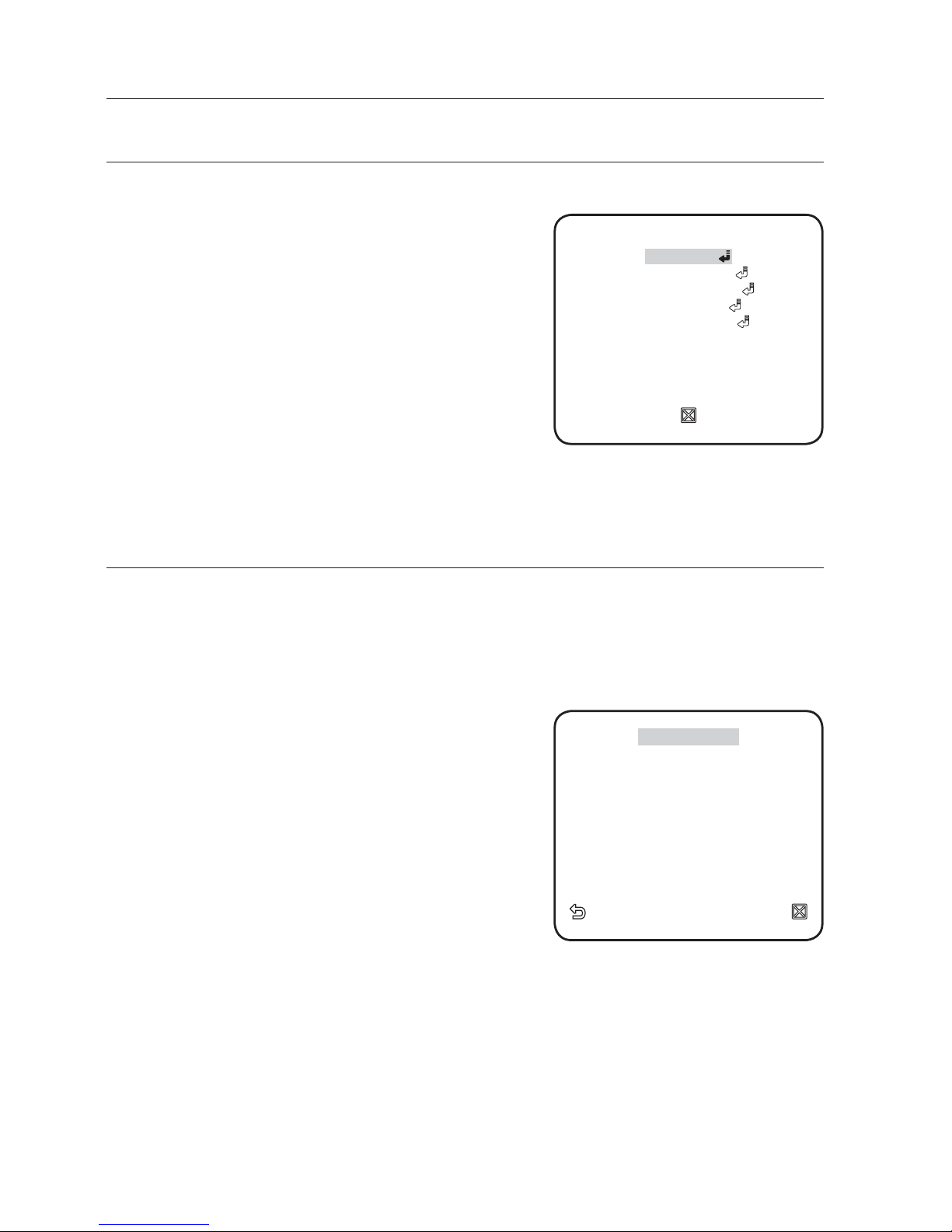
MAIN MENU
You can configure the camera settings to your preference.
PROFILE
You can select a mode that is appropriate to the
camera installation environment.
CAMERA SET
Confi gure the camera functions and settings.
PRIVACY ZONE
You can confi gure the privacy settings.
OTHER SET
You can confi gure more settings including
FACTORY DEFAULTS.
SYSTEM INFO
Shows the camera version and type.
PROFILE
You can select one from the pre-determined modes as appropriate to your specific camera installation
environment.
Your selection on each item in PROFILE will affect all other settings of the camera. For the setting,
refer to "PROFILE". (page
59)
For selecting and saving each menu item, refer to "How to use the keyboard controller". (page 17)
STANDARD
Automatically optimizes the camera settings to
the normal environment.
ITS
This setting enables you to analyze the traffi c
situation and take the traffi c information at a glance.
BACKLIGHT
This setting enables you to view a sharp background
and objects even in a severe backlight scene.
DAY/NIGHT
Automatically optimizes the camera settings to the day and night scene.
GAMING
This automatically confi gures the settings so that you can work in a stable illumination
condition as indoors.
BANK
Automatically optimizes the camera settings to the bank environment.
CUSTOM
Your change to any of the PROFILE settings will switch the display to CUSTOM.
y
y
y
y
y
y
y
y
y
y
y
y
◄
PROFILE
►
*
*
STANDARD
STANDARD
ITS
ITS
BACKLIGHT
BACKLIGHT
DAY/NIGHT
DAY/NIGHT
GAMING
GAMING
BANK
BANK
CUSTOM
CUSTOM
**
**
MAIN MENU
MAIN MENU
**
**
PROFILE
CAMERA SET
CAMERA SET
PRIVACY ZONE
PRIVACY ZONE
OTHER SET
OTHER SET
SYSTEM INFO
SYSTEM INFO
English _19
● CAMERA SETUP
CAMERA SETUP
You can configure the general settings of the camera module.
Use the four direction (
▲▼◄ ►
) buttons to select a desired item.
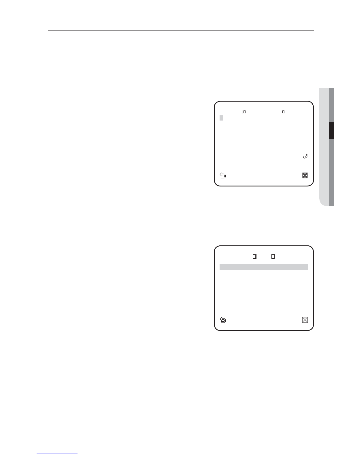
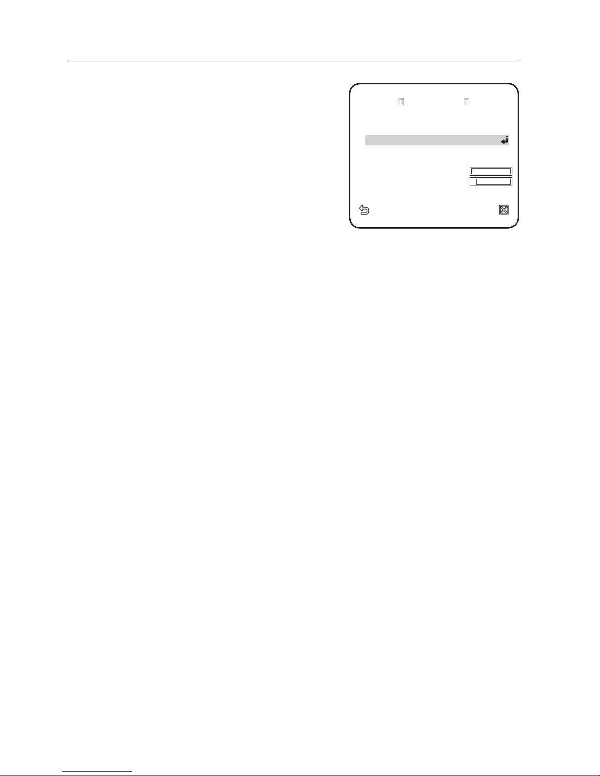
CAMERA ID
Provide the ID and position for a camera that displays on the screen.
For selecting and saving each menu item, refer to "How to use the keyboard controller". (page 17)
Select <CAMERA SET> - <CAMERA ID>.
Use the four direction (
▲▼◄ ►
) buttons to
select a desired character.
In the lower input box of the screen, the
selected character will be entered.
You can enter up to 54 characters including letters,
numbers and special characters.
When done, continue to select <LOCATION>
to specify the display position of the camera ID.
IRIS
You can set the iris to control the intensity of radiation entering to the camera.
For selecting and saving each menu item, refer to "How to use the keyboard controller". (page 17)
Select <CAMERA SET> - <IRIS>.
Use the left/right (
◄ ►
) buttons to select either
<ALC> or <ELC>.
ALC : Controls the luminance automatically.
LENS : Select a lens to use.
ELC : Controls the level electronically.
LEVEL : Select an overall brightness level.
BACKLIGHT :
Specify an area to compensate
for the backlight.
With <AREA> set to <USER>, you can specify the position and size.
If the iris is set to <ALC>, fi xing the iris is your priority when you adjust AE and the shutter speed.
1.
2.
3.
1.
2.
y
-
y
-
-
M
CAMERA ID
CAMERA ID
A
BCDEFGHIJKL MNOPQRSTUVWXYZO
BCDEFGHIJKLMNOPQRSTUVWXYZO
123456789
123456789
: ?
: ?
_
_
+
+
*( )/
*()/
SP►► ◄◄ SP LOCATION
SP►► ◄◄ SP LOCATION
-
- - - - - - - - - - - - - - - - - - - - - - - -
- - - - - - - - - - - - - - - - - - - - - - - -
- - - - - - - - - - - - - - - - - - - - - - - - -
- - - - - - - - - - - - - - - - - - - - - - - - -
ALC
ALC
LENS DC
LEVEL
LEVEL
[
[
00
00
]
]
----
----
I
I
----
----
BACKLIGHT OFF
BACKLIGHT OFF
20_ camera setup
camera setup
MOTION
You can specify a level of AGC for controlling the
camera motion.
Select F.FAST if you want to monitor a very fast
moving object in a low contrast scene, and S.SLOW
if monitoring a very slow moving, inanimate object in
the same condition.
As long as DAY/NIGHT is set to AUTO, the
<MOTION> menu is not available.
DNR
Reduces the noise on the screen.
This is useful, especially for a noisy screen.
Set it to <USER>, you can specify the level.
SHUTTER
The SHUTTER menu is used to set the fixed fast
electronic shutter or auto fast electronic shutter.
SENS-UP
If the brightness of the video signal is too low, the
Slow Shutter function will be activated.
Slow Shutter can collect the individual max frame rate to adjust the setting.
FLICKERLESS
If set to <ON>, the shutter speed will be fixed to 1/100 second. This will prevent possible
screen distortion due to a mismatch between the vertical sync frequency and the blinking
frequency of the lighting.
If IRIS is set to ELC / SHUTTER to AUTO, FIX, EXT mode / SENSE UP to FIX / AGC to FIX, the <DIS> menu
will be disabled.
XDR
This will correct a brightness difference between different scenes for the optimal visibility.
The higher the value is, the higher the correction level is.
DIS
Automatically compensates for the flicker on the screen.
If set to <ON>, the image will be enlarged with digital zoom as much area as
compensated.
If you set DIS to ON, the compensation area will be enlarged as set in the digital zoom factor.
If you set the digital zoom factor to greater than the enlarged zoom factor for the compensation, the DIS
function will be deactivated.
◄
CAMERA SET
►
CAMERA ID ON
CAMERA ID ON
IRIS ALC
IRIS ALC
MOTION (F.FAST)
MOTION (F.FAST)
---
---
DNR MID
DNR MID
SHUTTER OFF
SHUTTER OFF
SENS-UP AUTO X4
SENS-UP AUTO X4
FLICKERLESS OFF
FLICKERLESS OFF
XDR MID
XDR MID
DIS OFF
DIS OFF
DAY/NIGHT AUTO
WHITE BAL
WHITE BAL
DIGITAL ZOOM OFF
DIGITAL ZOOM OFF
DETAIL
DETAIL
[
[
2
2
]
]
AGC COLOR SUP MID
AGC COLOR SUP MID
POSI/NEGA +
POSI/NEGA +
PIP OFF
PIP OFF
English _21
● CAMERA SETUP
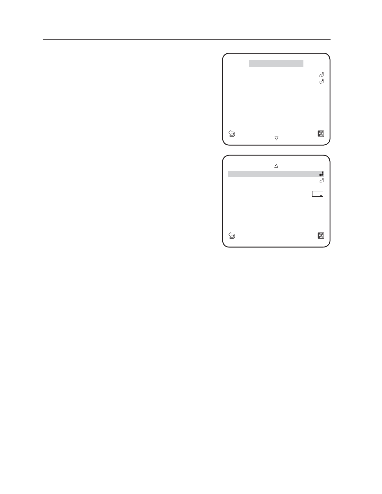
DAY/NIGHT
You can specify a recording mode according to the scene.
For selecting and saving each menu item, refer to "How to use the keyboard controller". (page 17)
Select <CAMERA SET> - <DAY/NIGHT>.
Select a screen transition mode according to the
illumination, and set options as appropriate.
DAY : Fixed to DAY mode, regardless of the
scene.
NIGHT : Fixed to NIGHT mode, regardless
of the scene.
If BURST is set to <ON>, the burst signal will
output.
AUTO : According to the luminance, this will
switch DAY to NIGHT mode, or vice versa.
DAYNIGHT / NIGHTDAY : If set to
<AUTO>, you can specify the brightness
level triggering the mode switch between
DAY and NIGHT as well as the interval.
MASK AREA : If there exists a bright spot
light source in a night scene, you can specify
the size and position as needed.
Any excessively bright area in a night scene
will be masked.
WHITE BAL
If you need to adjust the screen brightness, use the WHITE BALANCE function.
For selecting and saving each menu item, refer to "How to use the keyboard controller". (page 17)
Select <CAMERA SET> - <WHITE BAL>.
Select a mode where you set the balance.
DAY : You can set the RED, and BLUE value
in DAY mode.
NIGHT : You can adjust the <WHITE BAL>
according to the ambient luminance.
1.
2.
y
y
y
y
y
1.
2.
y
y
AUTO
AUTO
BURST OFF
DAY
DAY
NIGHT
NIGHT
BRIGHTNESS MID
BRIGHTNESS MID
DWELL TIME 2S
DWELL TIME 2S
NIGHT
NIGHT
DAY
DAY
BRIGHTNESS MID
BRIGHTNESS MID
DWELL TIME 5S
DWELL TIME 5S
MASK AREA 1 2
MASK AREA 1 2
WHITE BAL
WHITE BAL
DAY/NIGHT DAY
MODE ATW2
MODE ATW2
RED
RED
[
[
00
00
]
]
----
----
I
I
----
----
BLUE
BLUE
[
[
00
00
]
]
----
----
I
I
----
----
MASK AREA
MASK AREA
<SIZE>
<LOCATION>
<LOCATION>
22_ camera setup
camera setup
According to the specifi ed recording mode,
select a WHITE BAL mode with necessary
options.
BRIGHTNESS : Specify a brightness level
triggering the switch from DAY to NIGHT
mode.
MODE : According to the selected mode,
you can adjust the RED and BLUE color
level.
RED : Adjust the strength of the red color.
BLUE : Adjust the strength of the blue color.
R-GAIN/B-GAIN : Specify the current color temperature manually.
You can set the R-GAIN, and B-GAIN value only in AWC mode.
DIGITAL ZOOM
You can set the digital zoom factor and position.
When the zoom factor and position are defined, the digital zoom function will operate.
If you set the digital zoom to a larger factor than the actual enlargement for compensation, the DIS
function will be disabled.
DETAIL
You can adjust the vertical and horizontal sharpness, respectively.
AGC COLOR SUP
This will adjust the color scheme according to the AGC value.
POSI/NEGA
This will display the video brightness signal either normally or reversely.
PIP
You can view a main image with a sub image on the same screen.
If more than one privacy zone is set and the PRIVACY SET is set to ON, the PIP function will be
deactivated.
3.
y
y
-
-
-
WHITE BAL
WHITE BAL
DAY/NIGHT NIGHT
DAY/NIGHT NIGHT
BRIGHTNESS MID
BRIGHTNESS MID
MODE AWC
RED
RED
[
[
00
00
]
]
----
----
I
I
----
----
BLUE
BLUE
[
[
00
00
]
]
----
----
I
I
----
----
R-GAIN
R-GAIN
[
[
0040
0040
]
]
B-GAIN
B-GAIN
[
[
0133
0133
]
]
English _23
● CAMERA SETUP
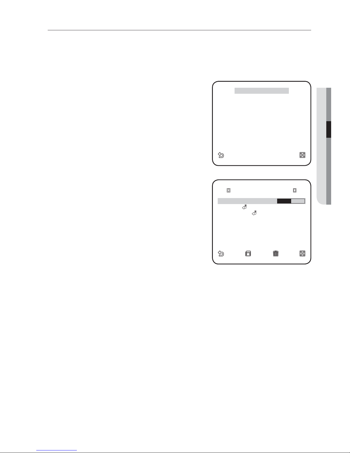
PRIVACY ZONE
You can set up to 12 privacy zones that will be hided for privacy of the subject when recording.
For selecting and saving each menu item, refer to "How to use the keyboard controller". (page 17)
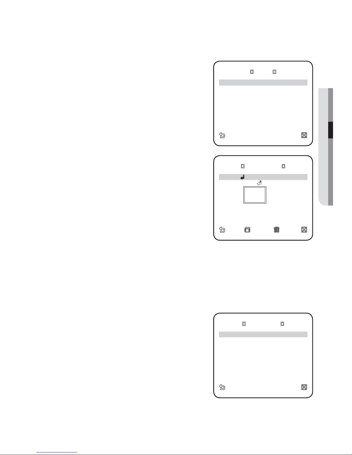
ZONE SETUP
Select <MAIN MENU> - <PRIVACY ZONE>.
Use the four direction (
▲▼◄ ►
) buttons to
select a desired number.
The Zone setup screen appears.
Select the <PIXEL LEVEL>.
Specify the pixel unit level for the POSITION
setting.
Select <POINT>.
You will see dots on the screen.
Use the four direction (
▲▼◄ ►
) buttons to specify
the position for each of the four dots.
Select <POSITION> and use the four direction
(
▲▼◄ ►
) buttons to specify the position for each
of the four dots.
Save the changes and move to the previous screen and select the <STYLE>.
Select <COLOR> and pick a desired color.
Setting one or more privacy zone and enabling privacy function will disable the PIP function.
1.
2.
3.
4.
5.
6.
7.
M
◄
PRIVACY ZONE
►
1 2 3 4 5 6
1 2 3 4 5 6
7 8 9 10 11 12
7 8 9 10 11 12
PRIVACY SET
PRIVACY SET
ON
ON
STYLE
STYLE
MOSAIC1
MOSAIC1
PRIVACY ZONE SET 1
PRIVACY ZONE SET 1
PIXEL LEVEL
[4]
<POINT>
<POINT>
<POSITION>
<POSITION>
24_ camera setup
camera setup
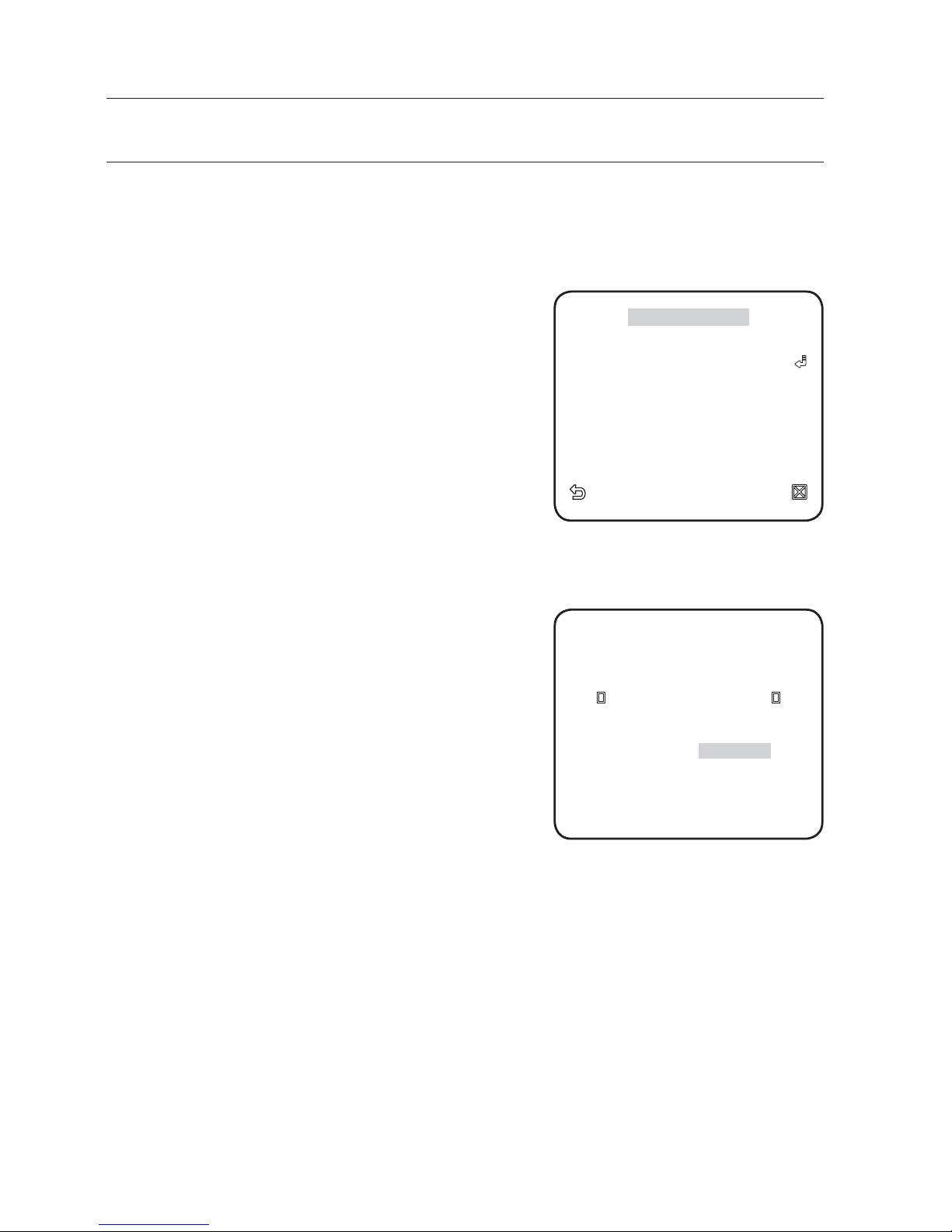
OTHERS
You can reset the camera, or select the OSD font color to your preference.
For selecting and saving each menu item, refer to "How to use the keyboard controller". (page 17)
LANGUAGE
You can slect a preferred language for the screen
display.
Select your language by using the left and right keys.
FACTORY DEFAULT
Select <MAIN MENU> - <OTHER SET>
- <FACTORY DEFAULTS>.
The FACTORY DEFAULTS setup screen
appears.
Select <OK>.
All the settings will be restored to the factory
default.
However, the language setting will not be
restored.
OSD COLOR
You can set the font color of the user interface.
1.
2.
◄
OTHER SET
►
LANGUAGE ENGLISH
LANGUAGE ENGLISH
FACTORY DEFAULTS
FACTORY DEFAULTS
OSD COLOR BW
OSD COLOR BW
FACTORY DEFAULTS
FACTORY DEFAULTS
OK
OK
CANCEL

English _25
● CAMERA SETUP
SYSTEM INFO
You can check the system information.
For selecting and saving each menu item, refer to "How to use the keyboard controller". (page 17)
Select <MAIN MENU> - <SYSTEM INFO>.
The current system information is displayed.
The camera type may different, depend on the video
signal.
1.
2.
M
◄
SYSTEM INFO
►
TYPE 3
TYPE 3
_
_
IPV
IPV
_
_
P
P
CAMERA VER. v2.00_100501
CAMERA VER. v2.00_100501
26_ network connection and setup
You can set up the network settings according to your network configurations.
Before installing or while using this program, visit the Samsung website www.samsungsecurity.com
and download and upgrade with the latest S/W version available.
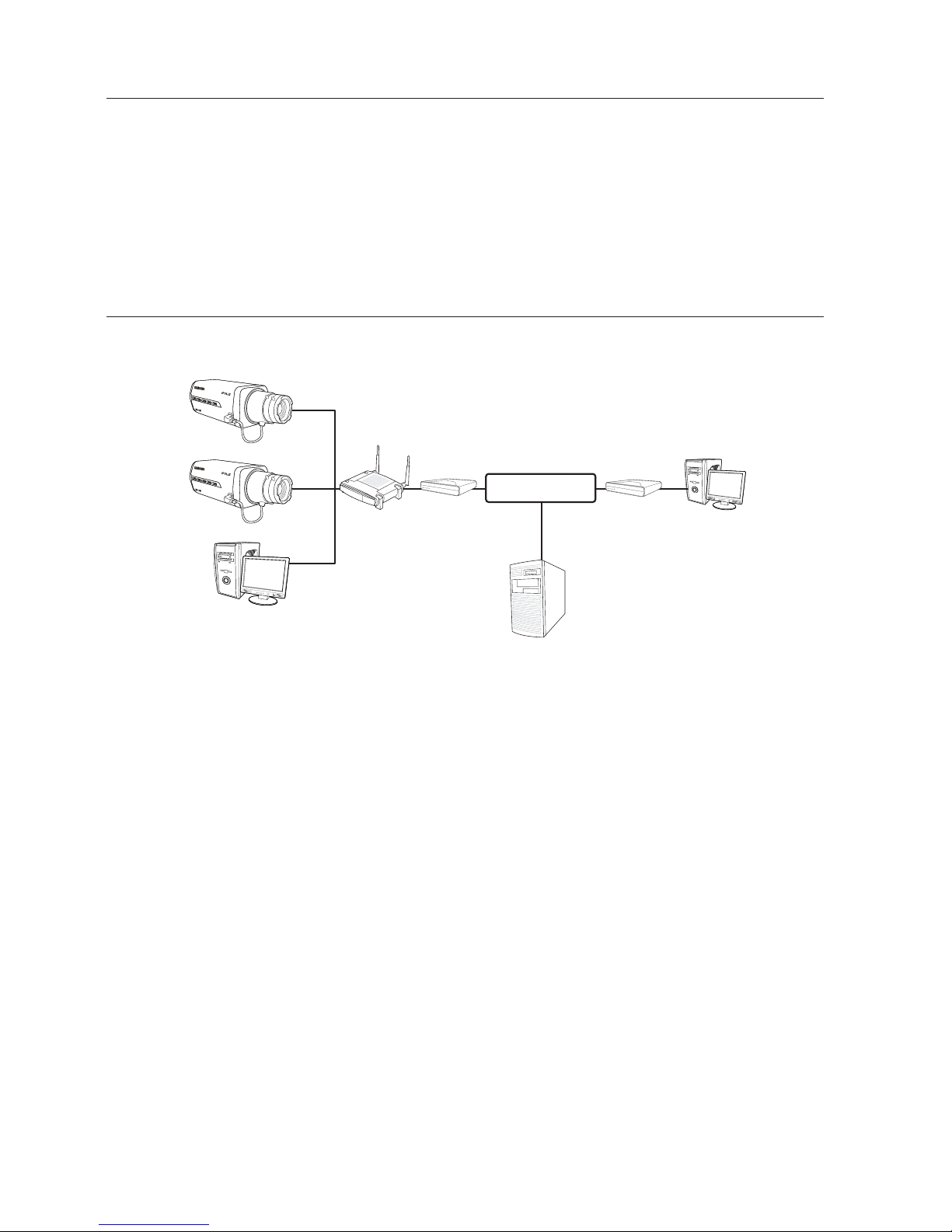
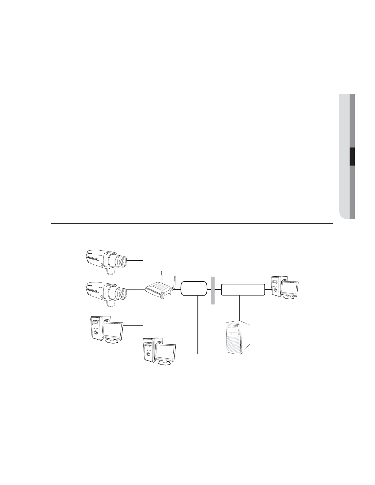
CONNECTING THE CAMERA TO AN BROADBAND ROUTER
WITH THE XDSL/CABLE MODEM
This is for a small network environment such as homes, SOHO and ordinary shops.
Configuring the network settings of the local PC connected to an
Broadband Router
Configuring the network settings of the local PC connected to an Broadband Router, follow
the instructions below.
Select : <Network Neighborhood> <Properties> <Local Area Connection>
<Properties> <General> <Internet Protocol (TCP/IP)> <Properties>
<Obtain an IP address automatically> or <Use the following IP address>.
Follow the instructions below if you select <Use the following IP address>:
ex1) If the address (LAN IP) of the Broadband Router is 192.168.1.1
IP address: 192.168.1.100
Subnet Mask: 255.255.255.0
Default Gateway: 192.168.1.1
ex2) If the address (LAN IP) of the Broadband Router is 192.168.0.1
IP address: 192.168.0.100
Subnet Mask: 255.255.255.0
Default Gateway: 192.168.0.1
M
y
y
로컬PC
IP공유기
xDSL 또는
Cable 모뎀
xDSL 또는
Cable 모뎀
외부 원격 PC
DDNS 서버
(Data Center, KOREA)
SNB-2000
SNB-2000
Local PC
Broadband
Router
xDSL or
Cable Modem
xDSL or
Cable Modem
External Remote PC
DDNS Server
(Data Center, KOREA)
INTERNET
network connection and setup
English _27
●
NETWORK CONNECTION AND SETUP
ex3) If the address (LAN IP) of the Broadband Router is 192.168.xxx.1
IP address: 192.168.xxx.100
Subnet Mask: 255.255.255.0
Default Gateway: 192.168.xxx.1
For the address of the Broadband Router, refer to the product’s documentation.
Checking if the Broadband Router is connected to the xDSL/Cable
modem properly
Select <Status> from the Settings menu of the Broadband Router
If it is properly connected, <IP Address>, <Subnet Mask> and <Gateway>
provided by your ISP are displayed. Please remember these values because they are
required so that an external remote computer of the Broadband Router connects to
the camera. However, note that certain ISPs change the settings of <IP Address>,
<Subnet Mask> and <Gateway> on a regular basis
If the Broadband Router is not properly connected, press the [Connect] button to try
to reconnect or check if the settings of the Broadband Router are correct.
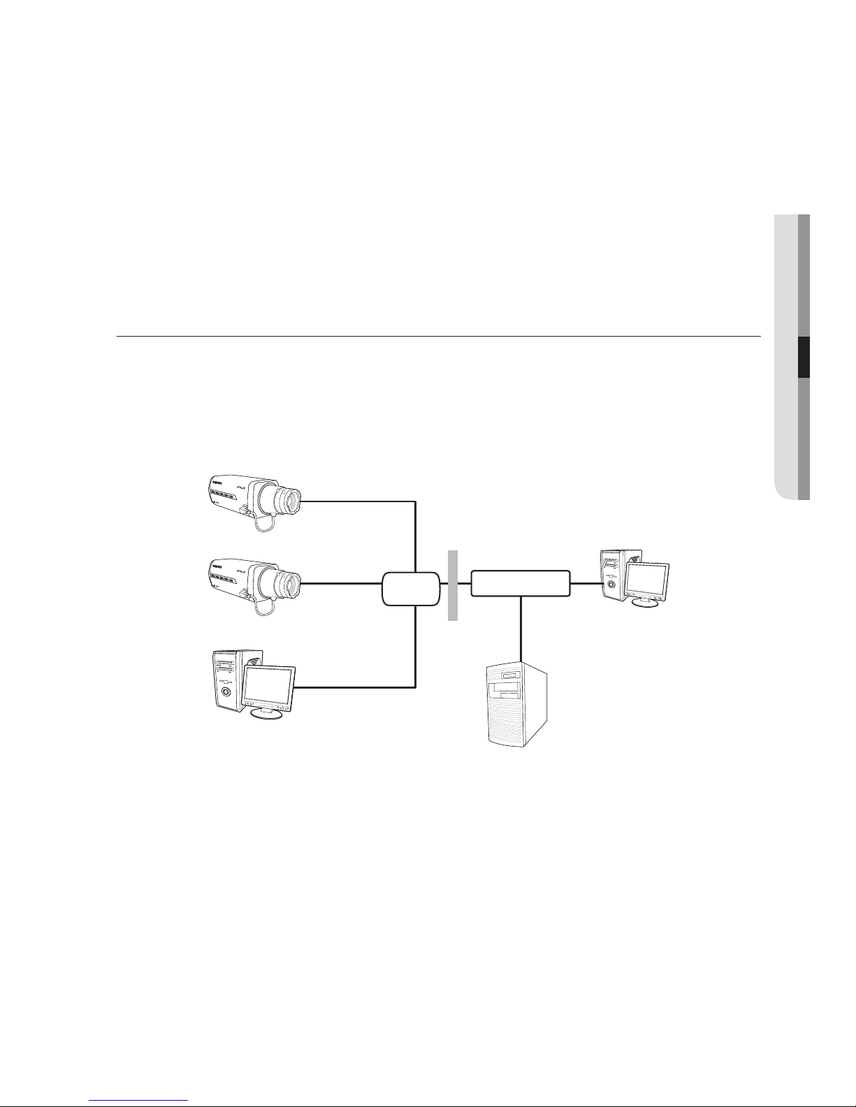
CONNECTING THE CAMERA TO AN BROADBAND ROUTER
WITH LOCAL AREA NETWORKING
This is for a large network environment such as corporate office, building, public office and factory.
Configuring the network settings of the local PC connected to an
Broadband Router
Configuring the network settings of the local PC connected to an Broadband Router, follow
the instructions below.
Select : <Network Neighborhood> <Properties> <Local Area Connection>
<Properties> <General> <Internet Protocol (TCP/IP)> <Properties>
<Obtain an IP address automatically> or <Use the following IP address>.
M
y
y
y
로컬 PC
공유기 외부 PC
방화벽
IP 공유기
외부 원격 PC
DDNS 서버
(Data Center, KOREA)
SNB-2000
SNB-2000
Local PC
Broadband
Router
External Remote PC
DDNS Server
(Data Center, KOREA)
Local PC
Firewall
INTERNET
Switch
HUB
28_ network connection and setup
network connection and setup
Follow the instructions below if you select <Use the following IP address>:
ex1) If the address (LAN IP) of the Broadband Router is 192.168.1.1
IP address: 192.168.1.100
Subnet Mask: 255.255.255.0
Default Gateway: 192.168.1.1
ex2) If the address (LAN IP) of the Broadband Router is 192.168.0.1
IP address: 192.168.0.100
Subnet Mask: 255.255.255.0
Default Gateway: 192.168.0.1
ex3) If the address (LAN IP) of the Broadband Router is 192.168.xxx.1
IP address: 192.168.xxx.100
Subnet Mask: 255.255.255.0
Default Gateway: 192.168.xxx.1
For the address of the Broadband Router, refer to the product’s documentation.
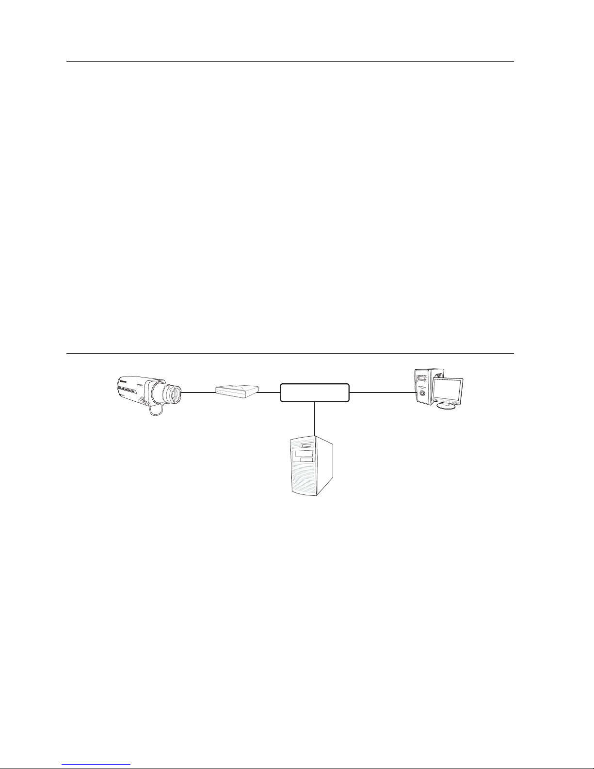
CONNECTING THE CAMERA DIRECTLY TO A DHCPBASED XDSL/CABLE MODEM
Setting the Broadband Router
This is enabled for a modem using DHCP.
Set the Static or Dynamic IP address. (pages
31~34)
Launch an Internet browser on the local PC connected to the Broadband Router.
Enter the Broadband Router’s address in the address bar of the browser.
ex) http://192.168.1.1, http://192.168.0.1
or http://192.168.xxx.1
For the DDNS URL address, refer to "To check the DDNS address". (page
38)
y
M
1.
2.
3.
xDSL 또는
Cable 모뎀
외부 원격 PC
DDNS 서버
(Data Center, KOREA)
SNB-2000
External Remote PC
DDNS Server
(Data Center, KOREA)
xDSL or
Cable Modem
INTERNET
English _29
●
NETWORK CONNECTION AND SETUP
When the Broadband Router is connected, the login window appears and prompts
you to enter the password.
For the login IP and the password, refer to the Broadband Router’s documentation.
When done, you will see the setup window of the Broadband Router. In the setup
menu, select “Automatic Confi guration-DHCP” for Internet Connection Type.
For the menu location of Internet Connection Type or DHCP selection, refer to the Broadband
Router’s documentation.
When done, click the [Save] or [Apply] button to save the settings.
CONNECTING THE CAMERA DIRECTLY TO LOCAL AREA
NETWORKING
Connecting to the camera from a local PC in the LAN
Launch an Internet browser on the local PC.
Enter the IP address of the camera in the address bar of the browser.
A remote PC in an external Internet out of the LAN network may not be able to connect to the
camera installed in the intranet if the port-forwarding is not properly set or a fi rewall is set.
In this case, to resolve the problem, contact your network administrator.
4.
5.
6.
1.
2.
M
로컬 PC
외부 원격 PC
방화벽
DDNS 서버
(Data Center, KOREA)
SNB-2000
SNB-2000
Local PC
Firewall
External Remote PC
DDNS Server
(Data Center, KOREA)
INTERNET
Switch
HUB
30_ network connection and setup
network connection and setup
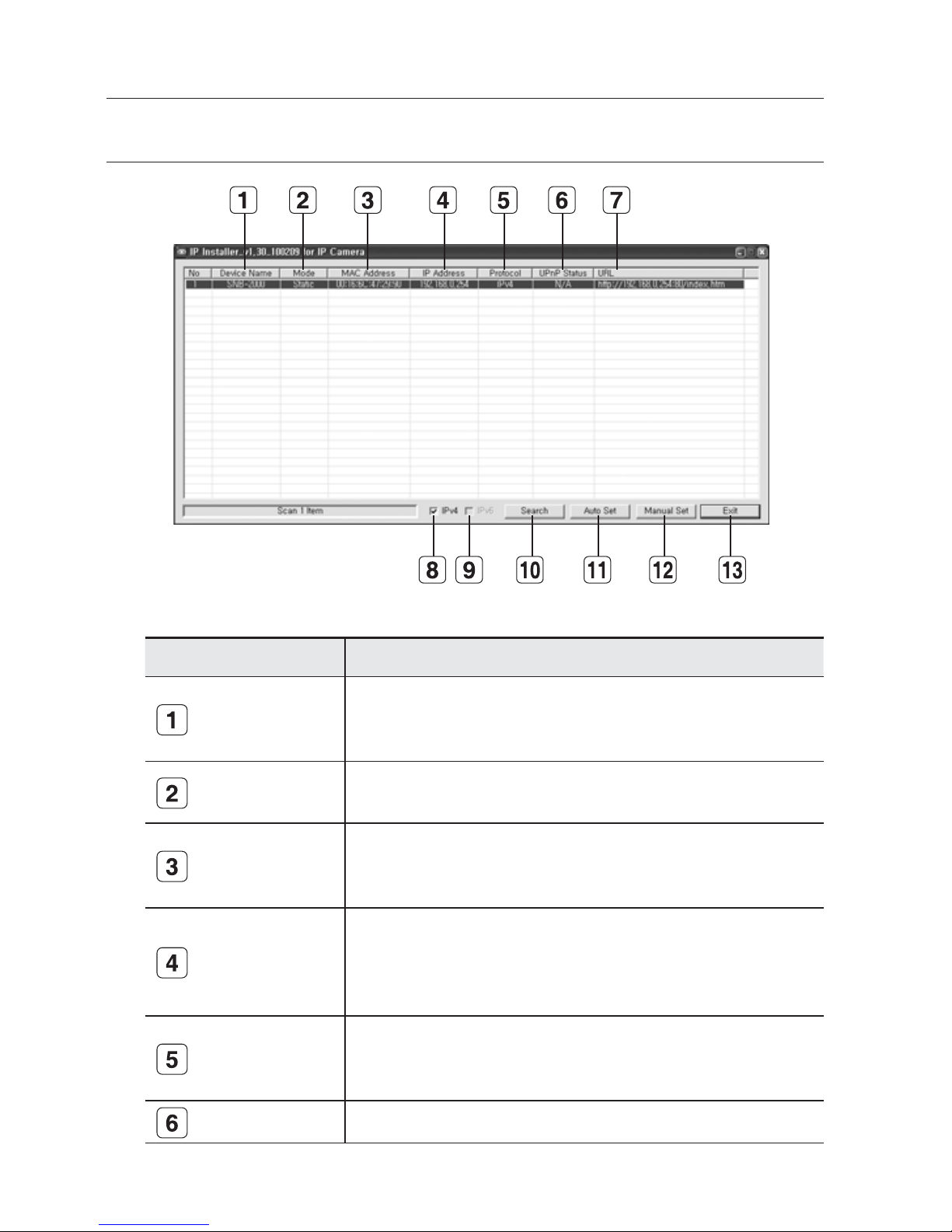
IP ADDRESS SETUP
Buttons used in IP Installer
Item Description
Device Name
Model name of the connected camera.
Click the column to sort the list by model name.
However, search will be stopped if clicked during the search.
Mode
Displays either <Static> or <Dynamic> for the current network connection
status.
MAC(Ethernet)
Address
Ethernet address for the connected camera.
Click the column to sort the list by Ethernet address.
However, search will be stopped if clicked during the search.
IP Address
IP address.
Click the column to sort the list by IP address.
However, search will be stopped if clicked during the search.
The factory default is "192.168.1.200".
Protocol
Network setting for the camera.
The factory default is "IPv4".
Cameras with the IPv6 setting will be displayed "IPv6".
UPnP Status This function is not currently implemented.

English _31
●
NETWORK CONNECTION AND SETUP
URL
DDNS URL address enabling access from the external Internet.
However, this will be replaced with the <IP Address> of the camera if
DDNS registration has failed.
IPv4 Scans for cameras with the IPv4 setting.
IPv6 Scans for cameras with the IPv6 setting.
Search
Scans for cameras that are currently connected to the network.
However, this button will be grayed out if neither IPv4 nor IPv6 is checked.
Auto Set <IP Installer> will automatically configure the network settings for you.
Manual Set You should configure the network settings manually.
Exit Exits the IP Installer program.
STATIC IP SETUP
Manual Network Setup
Run <IP Installer.exe> to display the camera search list.
At the initial startup, both [Auto Set] and [Manual Set] will be grayed out.
For cameras found with the IPv6 setting, these buttons will be grayed out as the cameras do not
support this function.
Select a camera in the search list.
Find the MAC (Ethernet) address labeled
on the rear of the camera.
Both the [Auto Set] and [Manual Set]
buttons will be activated.
Click [Manual Set].
The MANUAL SET dialog appears.
The default values of <IP Address>,
<Subnet Mask>, <Gateway>, and <HTTP Port> of the camera will be displayed.
The default <PASSWORD> is 4321.
In the <ADDRESS> pane, provide the
necessary information.
MAC (Ethernet) Address : The MAC
(Ethernet) address of the applicable
camera will be set automatically so you
don't need to input it manually.
M
1.
2.
3.

32_ network connection and setup
network connection and setup
If using an Broadband Router :
IP Address : Enter an address falling in
the IP range provided by the Broadband
Router.
ex) 192.168.1.2~254,
192.168.0.2~254,
192.168.XXX.2~254
Subnet Mask : The <Subnet Mask>
of the Broadband Router will be the
<Subnet Mask> of the camera.
Gateway : The <Local IP Address> of the Broadband Router will be the <Gateway>
of the camera.
If not using an Broadband Router :
For setting <IP Address>, <Subnet Mask>, and <Gateway>, contact your network
administrator.
The values of VNP, TCP, UDP, Upload, and Multicast ports can not be changed manually, and will
be adjusted according to the HTTP port value.
In the <PORT> pane, provide necessary
information.
HTTP Port : Used to access the
camera using the Internet browser,
defaulted to 80. Use the spin button
to change the HTTP Port value. The
start value of the port is 80, and
increases or decreases by 6 like
10000, 10006, 10012.
VNP Port : Used to control the video signal transfer, defaulted to 60001(TCP).
TCP Port : Video signal transfer port using TCP protocols, defaulted to
60002(TCP).
UDP Port : Video signal transfer port using the UDP Unicast method, defaulted to
60003(UDP).
Upload Port : Used to upgrade the software fi rmware, defaulted to 60004(TCP).
Multicast Port : Video signal transfer port using the UDP Multicast method,
defaulted to 60005(UDP).
Enter the password.
This is the login password for the "admin" user who accesses the camera.
The default password is "4321".
y
y
y
M
4.
y
y
y
y
y
y
5.

English _33
●
NETWORK CONNECTION AND SETUP
Click [OK].
Manual network setup will be completed.
When the manual setup including <IP> is completed, the camera will restart.
If the Broadband Router has more than one camera connected
Configure the IP related settings and the Port related settings distinctly with each other.
Category Camera #1 Camera #2
IP related settings
IP Address
Subnet Mask
Gateway
192.168.1.200
255.255.255.0
192.168.1.1
192.168.1.201
255.255.255.0
192.168.1.1
Port related settings
HTTP Port
VNP Port
TCP Port
UDP Port
Upload Port
Multicast Port
80
60001
60002
60003
60004
60005
10000
10001
10002
10003
10004
10005
If the <HTTP Port> is set other than 80, you must provide the <PORT> number in the address
bar of the Internet browser before you can access the camera.
ex) http://IP address : HTTP Port
http://192.168.1.201:10000
Auto Network Setup
Run <IP Installer.exe> to display the camera search list.
At the initial startup, both [Auto Set] and [Manual Set] will be grayed out.
For cameras found with the IPv6 setting, these buttons will be grayed out as the cameras do not
support this function.
Select a camera in the search list.
Find the MAC (Ethernet) address labeled
on the rear of the camera.
Both the [Auto Set] and [Manual Set]
buttons will be activated.
Click [Auto Set].
The AUTO SET dialog appears.
The <IP Address>, <Subnet Mask>,
and <Gateway> will be set automatically.
6.
7.
M
M
1.
2.

34_ network connection and setup
network connection and setup
Enter the password.
This is the login password for the
"admin" user who accesses the camera.
The default password is "4321".
Click [OK].
Auto network setup will be completed.
The camera will automatically complete
the network setting and restart.
DYNAMIC IP SETUP
Dynamic IP Environment Setup
Example of the dynamic IP environment
If an Broadband Router, with cameras connected, is assigned an IP address by
the DHCP server
If connecting the camera directly to the xDSL or cable modem using the DHCP
protocols
If IPs are assigned by the internal DHCP server via the LAN
Checking the dynamic IP
From a local PC, run <IP Installer>
to display a list of cameras that are
assigned <Dynamic IP>.
Select a camera in the list, and click
[Manual Set] to check the <Dynamic
IP> of the camera.
If you uncheck <DHCP>, you can
change <IP> or <PORT> to <STATIC>.
3.
4.
5.
y
-
-
-
1.
2.

English _35
●
NETWORK CONNECTION AND SETUP
PORT RANGE FORWARD (PORT MAPPING) SETUP
If you have installed an Broadband Router with a camera connected, you must set the port
range forwarding on the Broadband Router so that a remote PC can access the camera in it.
Manual Port Range Forwarding
From the Setup menu of the Broadband
Router, select <Applications &
Gaming> - <Port Range Forward>.
For setting the port range forward for
a third-party Broadband Router, refer
to the user guide of that Broadband
Router.
Select <TCP> and <UDP Port>
for each connected camera to the
Broadband Router.
Each port number for the Broadband
Router should match that specifi ed in
<Basic> - <IP> from the camera's
Setup menu.
When done, click [Save Settings].
Your settings will be saved.
CONNECTING TO THE CAMERA FROM A SHARED LOCAL
PC
Launch <IP Installer>.
It will scan for connected cameras and
display a list of them.
Double-click a camera to access.
The Internet browser starts and
connects to the camera.
You can also access the camera by typing the IP address of the camera in the address bar of the
Internet browser.
1.
2.
3.
1.
2.
M

36_ network connection and setup
network connection and setup
CONNECTING TO THE CAMERA FROM A REMOTE PC VIA
THE INTERNET
As a remote PC can not directly access <IP Installer>, you should access the camera in the
Broadband Router network using DDNS URL of the camera.
Before you can access a camera in the Broadband Router network, you should
have set the port range forward for the Broadband Router.
From the remote PC, launch the Internet browser and type the DDNS URL address
of the camera, or the IP address of the Broadband Router in the address bar.
ex) http://mfffe42.websamsung.net
For the DDNS URL address, refer to "To check the DDNS address". (page
38)
1.
2.

English _37
● WEB VIEWER
CONNECTING TO THE CAMERA
Normally, you would
Launch the Internet browser.
Type the IP address of the camera in
the address bar.
ex) •
IP address (IPv4) : 192.168.1.200
http://192.168.1.200
- the Login dialog should appear.
•
IP address
(IPv6) :
2001:230:abcd:
ffff:0000:0000:ffff:1111
http://[2001:230:abcd:ffff:0000
:0000:ffff:1111]
If the HTTP port is other than 80
Launch the Internet browser.
Type the IP address and HTTP port number of the camera in the address bar.
ex) IP address : 192.168.1.200:Port number(10000) http://192.168.1.200:10000
- the Login dialog should appear.
Using URL
Launch the Internet browser.
Type the DDNS URL of the camera in the address bar.
ex) URL address : http://mfffe42.websamsung.net
- the Login dialog should appear.
Connecting via URL (If the HTTP port is other than 80)
Launch the Internet browser.
Type the DDNS URL and HTTP port number of the camera in the address bar.
ex) URL address : http://mfffe42.websamsung.net:Port number(10000)
http://mfffe42.websamsung.net:10000
- the Login dialog should appear.
1.
2.
1.
2.
1.
2.
1.
2.
web viewer

web viewer
38_ web viewer
To check the DDNS address
The DDNS address consists of: <one of the lower-case letters: c, m, p> + <the last 6 digits
of the MAC (Ethernet) address> + <websamsung.net>
The small letter will be <c> if the first 6 digits of the MAC (Ethernet) address is <00:00:f0>,
or <m> if they are <00:16:6c>, or <p> for <00:68:36> , or <i> for <00:09:18>.
ex) - If the MAC (Ethernet) address is 00:00:f0:ff:fe:42: c + fffe42 + websamsung.net =
cfffe42.websamsung.net
-
If the MAC (Ethernet) address is 00:16:6c:ff:fe:42: m + fffe42 +websamsung.net =
mfffe42.websamsung.net
-
If the MAC (Ethernet) address is 00:68:36:ff:fe:42: p + fffe42 +websamsung.net =
pfffe42.websamsung.net
- If the MAC (Ethernet) address is 00:09:18:ff:fe:42: i + fffe42 +websamsung.net =
ifffe42.websamsung.net
J
The above mentioned addresses are simply examples; do not use any of these while connecting to
your system.
LOGIN
The default user ID is "admin", and the default password is "4321".
1. Enter "admin" in the <User Name>
input box.
2. Enter "4321" in the <Password> input
box.
If the password is changed, enter the
changed password instead.
3. Click [OK].
If you have logged in successfully, you
will the Live Viewer screen.
M
For security purposes, ensure that you change the password in <Basic> - <User>.
The administrator ID, "admin", is fixed and can not be changed.
If you check the "Save this password in your password list" option when your input is done, you will
be logged in automatically without being prompted to enter the login information from the next log in.
J
For this, your computer has installed DirectX 8.1 or later.
You can get a free download of the latest DirectX from http://www.microsoft.com/download.
If you are using Internet Explorer 7.0 or 8.0 as the default web browser, you can view the best
quality image with a screen ratio of 100%. Reducing the ratio may cut the image on the borders.

English _39
● WEB VIEWER
INSTALLING ACTIVEX
If connecting to a camera for the first time, you will see the installation message. Then, install the
required ActiveX to access the camera and control the video from it in real time.
For Windows XP Service Pack 2 users
Click the installation message that pops
up when you fi rst access the camera.
Click <Install ActiveX Control...>.
The security warning popup appears,
click [Install].
When the required ActiveX is installed
properly after your access to the camera,
the Live screen should appear.
For normal installation, set the Block
Popup setting as follows:
Internet Explorer ➝ Tools ➝ Block
Popup ➝ Always allow popups from
the current site(A)
1.
2.
3.
4.
J

web viewer
40_ web viewer
USING THE LIVE SCREEN
Item Description
Setup Move to the Setup screen.
About You can check the firmware version, serial number and manufacturer information.
Reset Alarm
Resets the Alarm icon. (the Alarm and Motion icons disappear.)
Capture Saves the snapshot as an image file in the .jpeg or .bmp format.
Print Prints out the current image.
Record Saves the snapshot as a video file in the .avi format.
Full Screen Displays the Live screen in full screen.
Video format
You can set the video format(MJPEG, H.264/MPEG4) for video files.
The context menu will differ, depending on the codec specified in <Select H.264 &
MPEG4 Video> of the active viewer.
Alarm output
On : Activates the specified Alarm Out port.
Off : Deactivates the specified Alarm Out port.
Pulse : Activates the Alarm Out port as much time as specified before deactivating it.
Camera OSD
Used to retrieve and customize the Camera Setup menu.
For selecting and saving each menu item, refer to "How to use the keyboard controller".
(page 17)
Viewer Screen Displays the Live video on the screen.

English _41
● WEB VIEWER
BACKUP
You can capture, print out, and save the snapshot in the specified path.
To capture the snapshot
Click [ ] on the scene to capture.
The Capture dialog should appear.
Click [OK].
The screenshot will be saved in the
specifi ed path.
Default fi le path
Windows XP : C:\Program Files\
Samsung\SNB-2000\SnapShot\Live
If you want to change the path, click [Set path (
)] and specify a path.
Windows Vista, Windows 7 : C:\users\[UserID]\Documents\Samsung\SNB-2000\
SnapShot\Live
On the Windows Vista, Windows 7 system, the path to save is fi xed.
The screenshot fi le will be named automatically in the format of <IP address_
Port number_YYYYMMDD_hhmmss_index>.
ex) 192.168.0.2000_60001_20000114_133857_00
To print out the screenshot
Click [ ] on the scene to print out.
The Print setup dialog appears.
Specify the name of the printer
connected, and click [OK].
1.
2.
y
-
-
y
1.
2.

web viewer
42_ web viewer
To record a video
Click [ ] on the scene to record.
You will see the Save AVI dialog;
provide the necessary information.
Save path : You can change the
default saving path.
File name : You can change the
default fi le name.
HDD minimum free size : If the free
space on the HDD is less than the
recorded space, recording will be forcibly ended.
Click [OK].
Recording will start with the display of
<REC> on the viewer screen.
The video file will be saved into the
specified path.
If you want to quit recording, click [
]
again.
Default fi le path
Windows XP : C:\Program Files\
Samsung\SNB-2000\VideoClip\
Live
If you want to change the path, click [Set path (
)] and specify a path.
Windows Vista, Windows 7 : C:\users\[UserID]\Documents\Samsung\
SNB-2000\VideoClip\Live
On the Windows Vista, Windows 7 system, the path to save is fi xed.
The screenshot fi le will be named automatically in the format of <IP address_
Port number_YYYYMMDD_hhmmss_index>.
ex) 192.168.0.200_60001_20090903_112350_00
If you want to play an .avi fi le, you must have installed the corresponding DivX
codec on your system.
You can get a free download of the DivX from http://sourceforge.net/projects/
ffdshow/.
A specific codec to MPEG4 is required before you can play videos in the MPEG4
format.
You can download the codec for MPEG4 videos from www.samsungsecurity.com.
1.
2.
y
y
y
3.
4.
y
-
-
y
y
y

English _43
● SETUP SCREEN
ACCESSING THE SETUP SCREEN
You can configure the default setting, system, overlay, event and network related settings, and
change them as necessary.
In the Live screen, click the <Setup> tab.
The Setup screen appears.
1.
2.
setup screen

setup screen
44_ setup screen
DEFAULT SETUP
To configure the video settings
You can set the video resolution and quality, and select the codec required.
Select <Basic> - <Video>.
The Video setup screen appears.
Brightness : Adjust the screen
brightness from 1 to 100.
Contrast : Adjust the contrast from
1 to 100.
Resolution : Set the video size of the
MPEG4, H.264, and MPEG fi les.
NTSC : 4CIF(704x480),
VGA(640X480), CIF(352X240)
PAL : 4CIF(704x576),
VGA(640X480), CIF(352X288)
Quality : Adjust the picture quality
from 1 to 10.
Frame rate : Select one from 30 fps,
15 fps, 8 fps, 3 fps, and 1 fps.
Bitrate control* : Select CBR (Constant
Bit Rate) or VBR (Variable Bit Rate) for
the compression method.
If selecting VBR, you can not set the target
bit rate.
Target bitrate : Transfers video signal
at a specifi ed bit rate.
Compression : Adjust the
compression rate from 5 through 100 by 5.
Encode priority : Set the video transfer method to Frame rate or Quality.
GOP* size : Select a GOP size between 5 and 15.
Deblock : This will soften the edges between macro blocks.
Profile : Select Baseline or Main for the H.264 profiling method.
Entropy coding* : Reduces the compression loss due to encoding.
Motion estimation :
Estimates the movement of pixels by determining the motion vector.
Flip mode : Turn upside down the image that is captured by the camera.
Mirror mode : Flip horizontal the image that is captured by the camera.
1.
y
y
y
-
-
y
y
y
y
y
y
y
y
y
y
y
y
y

English _45
● SETUP SCREEN
If you set the profi le to Baseline, the entropy coding is available only for CAVLC*; if you set it to
MAIN, the entropy coding is available for both CAVLC* and CABAC*.
When done, click [Apply].
Your settings will be saved.
To configure the IP settings
Select <Basic> - <IP>.
The IP setup window appears.
IP confi guration : Set the IP and port
settings for the camera.
IP type : Select one from <Static IP>,
<Dynamic IP>, and <PPPoE IP>.
If you select <PPPoE IP>, you can
provide the optional ADSL IP and
password. However, the multicast items
(multicast address, port, TTL) for VNP
and RTP will disappear.
MAC address : Displays the
Ethernet MAC address.
This is used for creating a DDNS
address.
IP address : Displays the current IP
address.
Subnet mask : Displays the
<Subnet mask> for the set IP.
Gateway : Displays the <Gateway> for the set IP.
DNS server : Displays the DNS(Domain Name Service) server address.
HTTP webserver port : HTTP port used to access the camera via the web
browser. The default is 80(TCP).
Upload port (TCP) : Used to upgrade the software fi rmware, defaulted to 60004(TCP).
IPv6 confi guration : Obtains the IPv6 address to access the IPv6 network.
VNP confi guration : Set a port used to transfer video signals with the Samsung
protocols.
Device port (TCP) : Used to control the video signal transfer, defaulted to 60001(TCP)
.
TCP streaming port : Video signal transfer port using TCP protocols, defaulted
to 60002(TCP).
UDP streaming port : UDP Port used to transfer video signal with the UDP
Unicast protocols. The default is 60003(UDP).
Multicast address : IP address used to transfer video signal with the UDP
Multicast protocols.
The default is 225.128.1.128, and if you want to change the address, specify it
ranging from 224.0.0.0 to 239.255.255.255.
J
2.
1.
y
-
-
-
-
-
-
-
-
y
y
-
-
-
-

setup screen
46_ setup screen
Multicast port : UDP Port used to transfer video signal with the UDP Multicast
protocols. The default is 60005(UDP).
TTL* : Set the TTL for the VNP packet.
The default is 63, and if you want to change the address, specify it ranging from
0 to 255.
RTP confi guration : You can set the RTP protocol.
RTSP port : You can set the RTSP port.
Streaming port : Used to transfer video signal with the RTP protocols.
The default range is between 61000 and 61999.
Multicast address : IP address used to transfer video signal with the RTP
protocols.
Multicast port : Used to transfer video signal with the RTP-protocol multicasting.
TTL* : You can set the TTL for the RTP packet.
When done, click [Apply].
Your settings are saved and the system restarts.
The currently opened web browser will be closed.
If the Broadband Router has more than one camera connected, you should confi gure IP and port
settings differently for each camera.
To set the user account
Click <Basic> - <User>.
The User setup window appears.
Login authentication : You can set to
authenticate the login by the user.
If you select <Enable>, the user
should have gone through the
login authentication; if selecting
<Disable>, every user can access
the system without the login authentication, having the ordinary user permissions.
When done, click [Apply].
User login ID/password list : Displays a list of accessible users ID, passwords, and
ratings.
You can add up to 10 users.
The admin ID is “admin”.
The password for the admin ID can be changed, but not added or deleted.
When done, click [Apply].
Your settings will be saved.
The currently opened web browser will be closed.
-
-
y
-
-
-
-
-
2.
M
1.
y
-
-
y
-
-
-
2.

English _47
● SETUP SCREEN
User Registration
From the User setup window, click
[Insert].
The Register User window appears.
Provide the <User ID>, <Password>,
and <Confi rm password>,
respectively. You can enter up to 9
alphanumeric or special characters
(some excluded) for the user ID and
password, respectively.
Select a user level.
Select either <Operator> or <User> for a new user's permission.
Click [Apply].
The user registration is completed.
An existing user ID can not be added duplicate.
Neither admin ID nor guest ID can be registered.
To edit a registered user account
From the User setup window, select a
user ID to change.
From the User setup window, click
[Modify].
The Modify user window appears.
Change the <User ID>, <Password>,
<Confi rm password>, and <Level> as
you wish.
Click [Apply].
The selected user ID will be changed.
To delete a user ID
From the User setup window, select a user ID to delete.
From the User setup window, click [Delete].
The selected user ID will be deleted.
About the user permission
Administrator : Can use all functions (change/control settings).
Operator : Can use only the functions available in the Live Viewer.
User : Can only view the video on the Live Viewer.
1.
2.
3.
4.
J
1.
2.
3.
4.
1.
2.
M

setup screen
48_ setup screen
To set the display language
Click <Basic> - <Language>.
The Language setup window appears.
You can select one from 7 languages
(English/Korean/Chinese/French/Italian/
Spanish/German).
When done, click [Apply].
The selected language will be applied.
SYSTEM SETUP
To set the date/time
You can obtain the current system time from the NTP server or your PC for your time
setting.
Select <System> - <Date & Time>.
The Date & Time setup window appears.
If you select Manual, input the date and
time manually.
Your settings will be saved.
Current system time : The specifi ed
time in System Time Setup will be
applied.
System time setup : You can
synchronize the system time with the NTP server (time server) or your PC, or
specify it manually.
You can specify the time between January 1, 2000 and December 31, 2037.
To set the system time
Select a desired address in <Address>
or select <Synchronize with PC
viewer>.
If you select Manual, input the date and
time manually.
Click [Apply].
The specifi ed system time will be applied.
1.
2.
1.
2.
y
y
M
1.
2.
3.

English _49
● SETUP SCREEN
<NTP Server IP> is provided by a public agency, the list of which is subject to change from time
to time.
In a local network, a separate NTP server must be manually defi ned.
The current time can vary depending on the computers regional (GMT and DST) and country (PC
time confi guration) settings.
To check the log information
Select <System> - <Log>.
The Log information list appears.
System log list : Shows the log
information about the system changes
along with time and IP address.
User login : Shows the current login
user to the camera.
Video confi guration change : Show
video setting changes.
System time change : Shows the time changes.
System started : Shows time when the camera is turned on.
The maximum of 2000 logs can be recorded.
If the log number is over 2000, the log in the bottom of the log list will be replaced with a new log.
To update the software
Select <System> - <Software update>.
The Software update window appears.
How to update the software
From the software update window, click
[Browse…].
The Open dialog appears.
Select an updatable fi le and click
[Open].
From the software update window,
click [Install].
The selected fi le will be unzipped with a
start of the update.
It may take a several minutes to
complete the update.
M
J
y
-
-
-
-
M
1.
2.
3.

setup screen
50_ setup screen
When the software update is completed, you will be prompted to restart the system.
Click [OK] to restart the system.
Since the current connection is disconnected, you have to connect to the system again.
If the network is disconnected, the power supply fails, or the PC abnormally operates during the
update, the system does not work at all.
To reset the system
Restart or reset the system if it does not work properly or causes a problem.
Select <System> - <Reset>.
The Reset window appears.
Restart : Restarts the system.
Factory default : Resets the system
settings to the factory defaults with
following two options:
Except network parameter : Resets all settings except for the Network Parameters.
All : Restores all settings to the default.
This works the same as pressing the [RESET] button on the rear of the camera.
After the system is reset or restarts, you should try to connect to the camera again.
It takes several minutes until the system completes rebooting. Wait until the system rebooting is
completed and try to connect again.
After executing <Factory default>, you must run the <IP Installer.exe> program to change the
basic network settings such as IP address, Subnet mask, Gateway, etc., before you can connect to
the Internet.
To set the HTTPS
Select <System> - <HTTPS>.
The HTTPS setup window appears.
Secure connection system : Select
a secure connection system to use.
To use the secure connection mode
requiring the public certifi cate for the
secure connection system, you must
have installed a signed certifi cate
issued by a certifi cate authority on
your system.
4.
5.
J
y
y
-
-
J
1.
y

English _51
● SETUP SCREEN
Install a public certifi cate : To install the camera’s certifi cate, you need to type a
certifi cate name (it can be arbitrarily assigned by user), certifi cate fi le issued from
the authority and a key fi le.
When done, click [Install].
If the certifi cate is installed successfully, the user-defi ned certifi cate name will be
displayed. Also, the option button of <HTTPS (Secure connection mode using
the public certifi cate)> in the upper side becomes activated.
To access the camera using HTTPS mode, you have to type the IP address for the camera in the
form of “https://<Camera_IP>”.
When done, click [Apply].
The web viewer will switch to the set secure connection system.
OVERLAY SETUP
You can display text on the screen.
To set the text
Select <Overlay> - <Overlay text>.
The Overlay Text setup window
appears.
When done, click [Apply].
Your settings will be saved.
Overlay text settings : If you select
<Disable>, the overlay text will not
be displayed; If selecting <Enable>, it will display on the screen.
Show date : Set to display the date information on the bottom screen.
Output Format : Select a display format of the date information.
YYYY-MM-DD : Year-Month- Day / MM-DD-YYYY : Month-Day-Year/
DD-MM-YYYY : Day-Month-Year
Show time : Set to display the time information on the bottom screen.
Output Format : Select a display format of the time information.
24hr : Displays the time in the 24-hour format.
12hr : Displays the time in the 12-hour format.
Text color : Select black or white for the text color.
Background color : Select black or white for the background color.
y
M
2.
1.
2.
y
y
-
y
-
y
y

setup screen
52_ setup screen
EVENT SETUP
To set the event transfer function
You can set the FTP/email server (SMTP) to transfer the alarm images present in the
camera, in case an alarm event occurs.
Select <Event> - <Transfer setup>.
The Image transfer setup window appears.
For more information on commercial
SMTP services, contact the SMTP service
provider.
To test the FTP transfer
Click [Test].
This will test if the image is transferred to the
specified FTP server properly.
When the test on the FTP server connection
and transfer is done, a message of
<( Verified )> will be displayed.
You will see an error message if the test
fails. If this is the case, check the FTP server
status or the settings again.
FTP transfer :
With this, you can transfer alarm images to the FTP server. If the initial FTP
server setting and the connection status are not verifi ed, the <( Not verifi ed )> message
appears.
Use passive mode : Select this option when the passive mode connection is
inevitable due to the fi rewall or FTP server setting.
FTP server address : Enter the IP address of a FTP server to which an alarm image
will be transferred.
M
y
-
-

English _53
● SETUP SCREEN
Upload path : You can specify the path of the FTP directory to which you will
transfer an alarm image.
You can specify the path by just typing </directory name> or <directory name> in
this fi eld.
If nothing is specifi ed, the path will be defaulted to the root directory of the FTP
server.
Port : The FTP port is defaulted to 21. This value can be changed according to the
FTP server setting.
User ID : Provide the user account ID to access the FTP server.
Password : Provide the user account password to access the FTP server.
E-mail(SMTP) transfer :
With this setting, you can transfer alarm images to the email
server. This function is available only for the SMTP email server.
When the initial SMTP
server setting and connection are not verified, the <( Not verified )> message appears.
SMTP server address : Enter the SMTP server address to use when you send an
email.
ex) 10.240.56.228
Port : Enter a port number to use when you send an email. The default is 25.
User ID : Provide the user account ID to access the SMTP server.
Password : Provide the user account password to access the SMTP server.
E-mail sender : Enter the address of the email sender. If the sender address is
incorrect, the email from the sender may be classifi ed as SPAM by the SMTP
server and may not be sent.
E-mail receiver : Enter the address of the email receiver.
Title : Enter the subject of the email to send.
Message : Enter the content of the email to send.
To test the email transfer
Click [Test].
This will test if the image is transferred to the
specified SMTP server properly. When the
test on the SMTP server connection and
transfer is done, a message of <( Verified )>
will be displayed.
You will see an error message if the test
fails.
If this is the case, check the SMTP server
status or the settings again.
-
-
-
-
y
-
-
-
-
-
-
-
-

setup screen
54_ setup screen
To set an alarm image
You can set to transfer the alarm image to the FTP/SMTP server.
Select a transfer method when an event occurs or the schedule transfer function is
activated.
Select <Event> - <Alarm image>.
The Alarm Image setup window
appears.
Transfer mode : Select an alarm
image transfer mode from FTP
transfer and E-mail transfer.
FTP transfer : The image is sent to
the specifi ed FTP address.
E-mail transfer : The image is sent
to the specifi ed email address.
Transferred image naming setup :
You can set the fi le name of an alarm image
to be sent when an alarm is triggered or during the scheduled transfer.
Pre/post alarm image : You can set to save the pre or post alarm image.
Number of image : The frame rate per second can be one among 1, 2, 3, and 5.
Pre-alarm duration : The pre alarm duration can be one among 5 seconds, 10
seconds, 15 seconds, and 30 seconds. You can send a pre-alarm image of up
to 30 seconds before the alarm is triggered.
(The max time differs, depending on the frame rate)
Post-alarm duration : The post alarm duration can be one among 5 seconds, 10
seconds, 15 seconds, and 30 seconds. You can send a post-alarm image of up
to 30 seconds after the alarm is triggered.
(The max time differs, depending on the frame rate)
The pre/post alarm duration is not available in SMTP transfer mode.
Only one image at the corresponding time will be transferred.
When done, click [Apply].
Your settings will be saved.
1.
y
-
-
y
y
-
-
-
M
2.

English _55
● SETUP SCREEN
To set the alarm input
Select <Event> - <Alarm input 1> or
<Alarm input 2>.
The Alarm Input setup window appears.
When done, click [Apply].
Your settings will be saved.
Input device setup : Select an input
type according to the characteristics
of the alarm sensor on the rear of the
camera.
Off : Turns off the alarm input setting.
NO (Normal Open) : It is normally open, but if it is closed, an alarm will be
triggered.
NC (Normal Close) : It is normally closed, but if it is open, an alarm will be
triggered.
Activation time : You can set a time to execute a specifi c command when an
alarm occurs.
Always : Always executes the specifi ed command when an alarm occurs.
Only scheduled time : Executes the specifi ed command when an alarm occurs
only on a specifi ed weekday, or time.
Action : You can set an action to execute when an alarm occurs.
Alarm output : Set the alarm output port to which the alarm signal is transferred.
Output duration : Set the period of time to output the alarm signal to the
specifi ed alarm output port when an alarm occurs.
If a new alarm event is detected during the alarm output, the delay time is
recalculated based on the detection time of the recent alarm.
Alarm image transfer : If you select <On>, you can transfer JPEG images to the FTP
or SMTP server according to the setting in <Event> - <Transfer setup>.
1.
2.
y
-
-
-
y
-
-
y
-
-
-

setup screen
56_ setup screen
To set the Motion Detection
Specify the use of motion detection.
Select a sensitivity level of the motion
detection.
Place the cursor at a point in the video
and drag it to whatever you need.
You can specify up to 4 motion detection
areas.
Specify the activation time and
activation condition.
For more information about <Activation
time> and <Action>, refer to “Alarm input”.
(page 55)
When done, click [Apply].
1.
2.
3.
4.
5.

English _57
● SETUP SCREEN
To set the scheduled transfer
You can set to transfer the JPEG image to the FTP/SMTP server at a specific interval.
Select <Event> - <Schedule>.
The Schedule Transfer setup window
appears.
Schedule transfer function :
If selecting <Enable>, the schedule
transfer function will be activated;
if selecting <Disable>, it will be
deactivated.
Transfer interval : You can set the
time interval to transfer images.
You can set the unit of the interval to <seconds> or <minutes>; you can also set to
transfer one image per 5/15/30/45/60 seconds, or one per 5/15/30/45/60 minutes.
Activation time : You can set a time to execute a specific command when a schedule transfer event occurs.
Always : Always sends an image at the set interval.
Only scheduled time : Sends the image only on a specifi ed weekday, or time.
If you select Manual, input the date and time manually.
Your settings will be saved.
1.
y
y
y
-
-
2.

setup screen
58_ setup screen
NETWORK SETUP
To set the video transfer mode
You can control the transfer rate according to the video transfer mode and network speed.
Select <Network> - <Streaming type>.
The Video Transfer setup window appears.
When done, click [Apply].
Your settings will be saved.
VNP streaming : You can set the
Samsung Protocol (VNP) for the
streaming service.
Protocol : Select a video transfer protocol from TCP*, UDP (Unicast)*, and UDP
(Multicast)*.
Multicast backbone (MBone) is not supported; you can access the camera only in the
multicast local network environment.
RTP streaming : You can set the RTP Protocol or the streaming service.
Protocol : Select a video transfer protocol from UDP (Unicast) and UDP (Multicast).
To set the DDNS
DDNS is an abbreviation of Dynamic Domain Name Service that converts the IP address
of a camera into a general Host Name so that the user can easily remember it and enables
connecting a camera with a fixed Host Name even if the IP address of the camera may be
dynamically changed.
Select <Network> - <DDNS>.
The DDNS setup window appears.
When done, click [Apply].
Your settings will be saved.
For checking the DDNS address, refer to
"To check the DDNS address".
(page
38)
1.
2.
y
-
y
-
1.
2.
M

English _59
● APPENDIX
PROFILE
CAMERA SETUP MENU
STANDARD ITS BACKLIGHT DAY/NIGHT GAMING BANK
Parent Menu
Sub-menus
IRIS
ALC ALC ALC ALC ALC ALC
ALC
------
LENS DC DC DC DC DC DC
LEVEL 000000
BACKLIGHT OFF OFF BLC OFF OFF WDR
MOTION
(F.FAST)
---
(F.FAST)
---
NORM
(F.FAST)
---
SLOW
(F.FAST)
---
DNR
MID MID MID MID MID MID
SHUTTER OFF AUTO 1/250 OFF OFF OFF OFF
SENSE UP AUTO X4 AUTO X2 AUTO X4 AUTO X4 AUTO X4 AUTO X4
XDR MID MID MID MID MID MID
DAY/NIGHT
AUTO AUTO DAY AUTO DAY AUTO
NIGHT ------
BURST OFF ON OFF OFF OFF OFF
WHITE BAL
DAY DAY/NIGHT DAY DAY/NIGHT DAY DAY
DAY
------
MODE
ATW2 ATW1 ATW1 ATW1 ATW1 ATW2
RED 000000
BLUE 000000
NIGHT
------
BRIGHTNESS
Custom Setting
MID
Custom Setting
MID
Custom Setting Custom Setting
MODE OFF ATW2 OFF ATW2 OFF
OFF
RED
Custom Setting
0
Custom Setting
0
Custom Setting Custom Setting
BLUE
Custom Setting
0
Custom Setting
0
Custom Setting Custom Setting
DETAIL 222222
appendix

appendix
60_ appendix
TERMINOLOGY
GOP : The default is 15, and if set to 15, one I-Frame will be output per 15 frames as one
I-Frame and 14 P-Frames constitute the GOP.
The lower the GOP size is, the better the quality is; however, the bit rate as well as the data
size will increase, causing a lower of the fps. GOP(Group of Pictures) is a set of video frames
for MPEG4 and H.264 format compression, indicating a collection of frames from the initial
I-Frame (key frame) to the next I-Frame. GOP consists of 2 kinds of frames: I-Frame and
P-Frame. I-Frame is the basic frame for the compression, also known as Key Frame, which
contains one complete image data. P-Frame contains only the data that has changed from
the preceding I-Frame.
Entropy coding : Data transfer technology used to reduce the compression loss from encoding.
CAVLC (Context-adaptive variable-length coding): Records a higher compression loss
rate than CABAC.
CABAC (Context-adaptive binary arithmetic coding): Shows a lesser compression loss than
CAVLC.
Bitrate Control
CBR(Constant Bitrate)
This will transfer video data in an equal size at all times, regardless of the video
complexity. The video quality may be deteriorated, depending on the video complexity.
VBR(Variable Bitrate)
The amount of video data to transfer may differ, depending on the video complexity. This
enables receiving video data in an equal quality at all times.
TTL : TTL stands for “Time To Live”, which you can specify to prevent loss of data packet that
passes through multiple-staged routers. Each router decreases the TTL value by one each
time a packet passes it through; If the TTL value reaches 0, the packet cannot further pass
through a router.
TCP : It is a general purpose protocol used for transmission that requires reliability. With
constant communication between the sender and recipient, it provides high reliability against
transmission data loss; however, it has imitation to transmit a large amount of data in real time
at a high speed.
It enables reliable data transmission over xDSL and cable network at a relatively slow speed.
UDP (Unicast): It refers to a system that transmits data between only one transmitter and one
receiver (1:1).
UDP (Multicast): It refers to the data transfer protocol in one-to-many (1:N) between the transmitting and receiving terminals; although it alleviates the network load, it requires <Multicast>
router.
For more information such as whether the network over which the camera is installed supports <Multicast>, contact the network administrator.
UDP :
It is a protocol appropriate to transmit a large amount of data such as multimedia data at a
high speed. However, with its nonconnection structure, it records a higher transmission efficiency
than TCP especially in a high LAN environment faster than 100Mbps.
y
y
-
-
y
-
-
y
y
y
y
y

English _61
● APPENDIX
SPECIFICATIONS
Item
Description
NTSC PAL
Camera
Type
Color/BW
Color
Image
Device 1/3" Super-HAD PS CCD
Pixels
Total 811 x 508 795 x 596
Effective 768 x 494 752 x 582
Scanning
System Progressive
Horizontal Frequency 15.734 Hz 15.625 Hz
Vertical Frequency 59.94 Hz 50 Hz
Min. Scene
Illumination
Color
Sens off : 0.12 Lux(15 IRE), 0.24 Lux(30 IRE),
0.4Lux(50 IRE)@F1.2
Sens up x512 : 0.00023 Lux(15 IRE), 0.00047 Lux(30 IRE),
0.0008Lux(50 IRE)@F1.2
B/W
Sens off : 0.012 Lux(15 IRE), 0.024 Lux(30 IRE),
0.04Lux(50 IRE)@F1.2
Sens up x512 : 0.000023 Lux(15 IRE), 0.000047 Lux(30
IRE), 0.00008Lux(50 IRE)@F1.2
Functions
Number of Privacy Zone 12 ea
Day/Night Day/Night/AUTO(Soft Method)
Extended Dynamic Range Off/On (Level Setting)
D-Zoom x1 ~ x16 (x0.1 STEP)
PIP Off/On (Advanced)
High Speed Shutter 1/60 ~ 1/10Ksec 1/50 ~ 1/10Ksec
Flickerless Off/On
Sens Up x2 ~ x512
BLC Off/On (Area Setting)
AGC Off/On (Max.Level Setting)
ELC Off/On ( ~ 1/200Ksec)
Camera ID Off/On (Max.54ea/2Line)
White Balance ATW1/ATW2/AWC/3200K/5600K
Digital Noise Reduction Off/On (Adaptive 3D+2D)
Digital Image Stablization Off/On
Etc. Function Detail, Reverse(H/V), Posi/Nega
Resolution
Horizontal 600 TV Lines
Vertical 350 TV Lines

appendix
62_ appendix
Item
Description
NTSC PAL
Video Output Video Output
VBS 1.0Vp-p
S/N Ratio S/N Ratio about 52 dB
Lens
Lens Drive Type MANUAL/AI(VIDEO/DC)
Mount Type CS/C
Network
Board
OS Embedded Linux
Hardware
Flash memory 32M byte
RAM 256M byte
DSP TI Davinci
Ethernet RJ-45 (10/100BASE-T)
PoE Yes (IEEE802.3af)
Alarm
Input 2 ea
Output 2 ea
Video
Compression
H.264 / MPEG4 / MJPEG Multiple Codec
(H.264 / MPEG4 selectable)
Simultaneous Dual Streaming
Resolution
4CIF 704x480 704x576
VGA 640x480
CIF 352x240 352x288
Frame Rate 30, 15, 8, 3, 1 fps 25, 13, 6, 3, 1 fps
Quality 1 ~ 10 level
OSD Camera Control and Adjustment
OSD menu on Video
(Menu enter/exit, move by Web UI)
* Some key adjustment menus will be supported by CGI API.
Motion
Detection
Sensitivity and Area Setting High, Medium, Low

English _63
● APPENDIX
Item
Description
NTSC PAL
Protocol
IP IPv4 / IPv6
Network
Protocol
IPv4
TCP/IP, UDP/IP, RTP(UDP), RTP(TCP), RTSP, NTP, HTTP,
HTTPS, SSL, DHCP
PPPoE, FTP, SMTP, ICMP, IGMP, SNMPv1/v2c/v3(MIB-2),
ARP, DNS, DDNS, VSIP
IPv6 TCP/IP, HTTP, HTTPS, SSL, DHCP
Streaming Unicast (TCP, UDP), Multicast (UDP)
Security
HTTPS Login Authentication
Digest Login Authentication
DDNS Supporting Samsung DDNS and Public DDNS services
ONVIF Conformance Yes
Connection
Maximum User Access
Max 10 Users at Unicast (TCP, UDP) Mode
Max 20 Users at Multicast (UDP) Mode
User Access
Level
Administrator
Live Monitoring, Alarm I/O control, OSD menu control,
SETUP
Operator Live Monitoring, Alarm I/O control
User Live Monitoring
Event
Management
Alarm Input
JPEG Image transfer : FTP, SMTP
Notification : notify to viewer or by E-mail (one image
attachment)
Alarm Out
Motion Detection
Schedule JPEG Image transfer : FTP, SMTP
Web Browser
Viewer
(Default)
Supported OS Windows XP, Windows VISTA, Windows 7
Supported Browser Internet Explorer 6.0 or Higher
UI Language E/F/G/S/I/C/K
S/W upgrade Support
Video Player RTP/RTSP streaming Quicktime, VLC player
Video
Management
Software
Samsung iPOLiS
3rd Party S/W appliction
Application IP Installation IP Installer Application for All Samsung IP Devices

appendix
64_ appendix
Item
Description
NTSC PAL
SDK
HTTP API CGI Command
Provides functionality to control cameras
and set/retrieve internal parameter values.
Get JPEG image or MJPEG stream
Alarm In/Out control
RTP/RTSP API RTP Header, RTSP Command Document
ActiveX SDK ActiveX API for viewing data streams from IP camera.
Power
AC24V±10%(60Hz±0.3Hz)/ DC12V+10%/-5% /
PoE (Power over Ethernet)
Power Consumption
Max. 6W(DC12V), Max. 7W(AC24V), Max. 8W(PoE)
Operating Temp. -10˚C~50˚C
Operating Humidity ~90%
Dimension (W X H X D) W72 X H60 X D139 mm
Weight About 425g

English _65
● APPENDIX
FRAME RATE (NTSC)
Test Condition: MJPEG - Resolution(CIF), Quality(1), Frame rate(1)
H.264 - Bitrate control(CBR), Compression(40), Encode Priority(Frame rate),
GOP size(15), Deblock(ON), Profi le(Baseline), Entropy coding(CAVLC),
Motion estimation(HPel)
MPEG4 - Bitrate control(CBR), Compression(40), Encode Priority(Frame rate),
GOP size(15)
MPEG4 (4CIF)
Frame Rate
Quality
30 FPS 15 FPS 8 FPS 3 FPS 1 FPS
LEVEL10
4239 Kbps
23 FPS
2765 Kbps
15 FPS
1290 Kbps
7 FPS
737 Kbps
4 FPS
221 Kbps
1 FPS
LEVEL9
3686 Kbps
24 FPS
2304 Kbps
15 FPS
1075 Kbps
7 FPS
614 Kbps
4 FPS
184 Kbps
1 FPS
LEVEL8
3072 Kbps
25 FPS
1843 Kbps
15 FPS
860 Kbps
7 FPS
492 Kbps
4 FPS
147 Kbps
1 FPS
LEVEL7
2396 Kbps
26 FPS
1382 Kbps
15 FPS
645 Kbps
7 FPS
369 Kbps
4 FPS
111 Kbps
1 FPS
LEVEL6
1659 Kbps
27 FPS
922 Kbps
15 FPS
430 Kbps
7 FPS
246 Kbps
4 FPS
74 Kbps
1 FPS
LEVEL5
1336 Kbps
29 FPS
691 Kbps
15 FPS
323 Kbps
7 FPS
184 Kbps
4 FPS
55 Kbps
1 FPS
LEVEL4
1133 Kbps
30 FPS
576 Kbps
15 FPS
269 Kbps
7 FPS
154 Kbps
4 FPS
46 Kbps
1 FPS
LEVEL3
922 Kbps
30 FPS
461 Kbps
15 FPS
215 Kbps
7 FPS
123 Kbps
4 FPS
37 Kbps
1 FPS
LEVEL2
691 Kbps
30 FPS
346 Kbps
15 FPS
161 Kbps
7 FPS
92 Kbps
4 FPS
28 Kbps
1 FPS
LEVEL1
461 Kbps
30 FPS
230 Kbps
15 FPS
108 Kbps
7 FPS
61 Kbps
4 FPS
18 Kbps
1 FPS
M
❖

appendix
66_ appendix
H.264 (4CIF)
Frame Rate
Quality
30 FPS 15 FPS 8 FPS 3 FPS 1 FPS
LEVEL10
2298 Kbps
19 FPS
1229 Kbps
10 FPS
737 Kbps
6 FPS
369 Kbps
3 FPS
147 Kbps
1 FPS
LEVEL9
1751 Kbps
19 FPS
1198 Kbps
13 FPS
645 Kbps
7 FPS
369 Kbps
4 FPS
111 Kbps
1 FPS
LEVEL8
1536 Kbps
20 FPS
1075 Kbps
14 FPS
538 Kbps
7 FPS
307 Kbps
4 FPS
92 Kbps
1 FPS
LEVEL7
1352 Kbps
22 FPS
897 Kbps
15 FPS
430 Kbps
7 FPS
246 Kbps
4 FPS
74 Kbps
1 FPS
LEVEL6
1129 Kbps
25 FPS
691 Kbps
15 FPS
369 Kbps
8 FPS
184 Kbps
4 FPS
55 Kbps
1 FPS
LEVEL5
960 Kbps
25 FPS
576 Kbps
15 FPS
307 Kbps
8 FPS
154 Kbps
4 FPS
46 Kbps
1 FPS
LEVEL4
799 Kbps
26 FPS
461 Kbps
15 FPS
246 Kbps
8 FPS
123 Kbps
4 FPS
37 Kbps
1 FPS
LEVEL3
622 Kbps
27 FPS
346 Kbps
15 FPS
184 Kbps
8 FPS
92 Kbps
4 FPS
28 Kbps
1 FPS
LEVEL2
445 Kbps
29 FPS
230 Kbps
15 FPS
123 Kbps
8 FPS
61 Kbps
4 FPS
18 Kbps
1 FPS
LEVEL1
223 Kbps
29 FPS
115 Kbps
15 FPS
61 Kbps
8 FPS
31 Kbps
4 FPS
9 Kbps
1 FPS
❖

English _67
● APPENDIX
MPEG4 (VGA)
Frame Rate
Quality
30 FPS 15 FPS 8 FPS 3 FPS 1 FPS
LEVEL10
4055 Kbps
22 FPS
2580 Kbps
14 FPS
1290 Kbps
7 FPS
737 Kbps
4 FPS
221 Kbps
1 FPS
LEVEL9
3533 Kbps
23 FPS
2304 Kbps
15 FPS
1075 Kbps
7 FPS
614 Kbps
4 FPS
184 Kbps
1 FPS
LEVEL8
2949 Kbps
24 FPS
1843 Kbps
15 FPS
860 Kbps
7 FPS
492 Kbps
4 FPS
147 Kbps
1 FPS
LEVEL7
2304 Kbps
25 FPS
1382 Kbps
15 FPS
645 Kbps
7 FPS
369 Kbps
4 FPS
111 Kbps
1 FPS
LEVEL6
1536 Kbps
25 FPS
922 Kbps
15 FPS
430 Kbps
7 FPS
246 Kbps
4 FPS
74 Kbps
1 FPS
LEVEL5
1152 Kbps
25 FPS
691 Kbps
15 FPS
323 Kbps
7 FPS
184 Kbps
4 FPS
55 Kbps
1 FPS
LEVEL4
998 Kbps
26 FPS
576 Kbps
15 FPS
269 Kbps
7 FPS
154 Kbps
4 FPS
46 Kbps
1 FPS
LEVEL3
799 Kbps
26 FPS
461 Kbps
15 FPS
246 Kbps
8 FPS
123 Kbps
4 FPS
37 Kbps
1 FPS
LEVEL2
622 Kbps
27 FPS
346 Kbps
15 FPS
184 Kbps
8 FPS
92 Kbps
4 FPS
28 Kbps
1 FPS
LEVEL1
415 Kbps
27 FPS
230 Kbps
15 FPS
123 Kbps
8 FPS
61 Kbps
4 FPS
18 Kbps
1 FPS
❖

appendix
68_ appendix
H.264 (VGA)
Frame Rate
Quality
30 FPS 15 FPS 8 FPS 3 FPS 1 FPS
LEVEL10
2089 Kbps
17 FPS
1229 Kbps
10 FPS
737 Kbps
6 FPS
369 Kbps
3 FPS
147 Kbps
1 FPS
LEVEL9
1659 Kbps
18 FPS
1014 Kbps
11 FPS
553 Kbps
6 FPS
276 Kbps
3 FPS
111 Kbps
1 FPS
LEVEL8
1459 Kbps
19 FPS
845 Kbps
11 FPS
538 Kbps
7 FPS
307 Kbps
4 FPS
92 Kbps
1 FPS
LEVEL7
1229 Kbps
20 FPS
737 Kbps
12 FPS
430 Kbps
7 FPS
246 Kbps
4 FPS
74 Kbps
1 FPS
LEVEL6
1014 Kbps
22 FPS
691 Kbps
15 FPS
323 Kbps
7 FPS
184 Kbps
4 FPS
55 Kbps
1 FPS
LEVEL5
883 Kbps
23 FPS
576 Kbps
15 FPS
269 Kbps
7 FPS
154 Kbps
4 FPS
46 Kbps
1 FPS
LEVEL4
707 Kbps
23 FPS
461 Kbps
15 FPS
215 Kbps
7 FPS
123 Kbps
4 FPS
37 Kbps
1 FPS
LEVEL3
553 Kbps
24 FPS
346 Kbps
15 FPS
161 Kbps
7 FPS
92 Kbps
4 FPS
28 Kbps
1 FPS
LEVEL2
384 Kbps
25 FPS
230 Kbps
15 FPS
108 Kbps
7 FPS
61 Kbps
4 FPS
18 Kbps
1 FPS
LEVEL1
200 Kbps
26 FPS
115 Kbps
15 FPS
54 Kbps
7 FPS
31 Kbps
4 FPS
9 Kbps
1 FPS
❖

English _69
● APPENDIX
MPEG4 (CIF)
Frame Rate
Quality
30 FPS 15 FPS 8 FPS 3 FPS 1 FPS
LEVEL10
1382 Kbps
30 FPS
691 Kbps
15 FPS
369 Kbps
8 FPS
184 Kbps
4 FPS
55 Kbps
1 FPS
LEVEL9
1152 Kbps
30 FPS
576 Kbps
15 FPS
307 Kbps
8 FPS
154 Kbps
4 FPS
46 Kbps
1 FPS
LEVEL8
922 Kbps
30 FPS
461 Kbps
15 FPS
246 Kbps
8 FPS
123 Kbps
4 FPS
37 Kbps
1 FPS
LEVEL7
691 Kbps
30 FPS
346 Kbps
15 FPS
184 Kbps
8 FPS
92 Kbps
4 FPS
28 Kbps
1 FPS
LEVEL6
461 Kbps
30 FPS
230 Kbps
15 FPS
123 Kbps
8 FPS
61 Kbps
4 FPS
18 Kbps
1 FPS
LEVEL5
346 Kbps
30 FPS
173 Kbps
15 FPS
92 Kbps
8 FPS
46 Kbps
4 FPS
14 Kbps
1 FPS
LEVEL4
288 Kbps
30 FPS
144 Kbps
15 FPS
77 Kbps
8 FPS
38 Kbps
4 FPS
12 Kbps
1 FPS
LEVEL3
230 Kbps
30 FPS
115 Kbps
15 FPS
61 Kbps
8 FPS
31 Kbps
4 FPS
9 Kbps
1 FPS
LEVEL2
173 Kbps
30 FPS
86 Kbps
15 FPS
46 Kbps
8 FPS
23 Kbps
4 FPS
7 Kbps
1 FPS
LEVEL1
151 Kbps
30 FPS
76 Kbps
15 FPS
40 Kbps
8 FPS
20 Kbps
4 FPS
6 Kbps
1 FPS
❖

appendix
70_ appendix
H.264 (CIF)
Frame Rate
Quality
30 FPS 15 FPS 8 FPS 3 FPS 1 FPS
LEVEL10
922 Kbps
30 FPS
461 Kbps
15 FPS
215 Kbps
7 FPS
123 Kbps
4 FPS
37 Kbps
1 FPS
LEVEL9
691 Kbps
30 FPS
346 Kbps
15 FPS
184 Kbps
8 FPS
92 Kbps
4 FPS
28 Kbps
1 FPS
LEVEL8
576 Kbps
30 FPS
288 Kbps
15 FPS
134 Kbps
7 FPS
77 Kbps
4 FPS
23 Kbps
1 FPS
LEVEL7
461 Kbps
30 FPS
230 Kbps
15 FPS
108 Kbps
7 FPS
61 Kbps
4 FPS
18 Kbps
1 FPS
LEVEL6
346 Kbps
30 FPS
173 Kbps
15 FPS
81 Kbps
7 FPS
46 Kbps
4 FPS
14 Kbps
1 FPS
LEVEL5
288 Kbps
30 FPS
144 Kbps
15 FPS
67 Kbps
7 FPS
38 Kbps
4 FPS
12 Kbps
1 FPS
LEVEL4
230 Kbps
30 FPS
115 Kbps
15 FPS
54 Kbps
7 FPS
31 Kbps
4 FPS
9 Kbps
1 FPS
LEVEL3
173 Kbps
30 FPS
86 Kbps
15 FPS
40 Kbps
7 FPS
23 Kbps
4 FPS
7 Kbps
1 FPS
LEVEL2
115 Kbps
30 FPS
58 Kbps
15 FPS
27 Kbps
7 FPS
15 Kbps
4 FPS
5 Kbps
1 FPS
LEVEL1
58 Kbps
30 FPS
29 Kbps
15 FPS
13 Kbps
7 FPS
8 Kbps
4 FPS
2 Kbps
1 FPS
❖

English _71
● APPENDIX
FRAME RATE (PAL)
Test Condition: MJPEG - Resolution(CIF), Quality(1), Frame rate(1)
H.264 - Bitrate control(CBR), Compression(40), Encode Priority(Frame rate),
GOP size(15), Deblock(ON), Profi le(Baseline), Entropy coding(CAVLC),
Motion estimation(HPel)
MPEG4 - Bitrate control(CBR), Compression(40), Encode Priority(Frame rate),
GOP size(15)
MPEG4 (4CIF)
Frame Rate
Quality
25 FPS 13 FPS 6 FPS 3 FPS 1 FPS
LEVEL10
4645 Kbps
21 FPS
2654 Kbps
12 FPS
1327 Kbps
6 FPS
664 Kbps
3 FPS
221 Kbps
1 FPS
LEVEL9
4055 Kbps
22 FPS
2212 Kbps
12 FPS
1106 Kbps
6 FPS
553 Kbps
3 FPS
184 Kbps
1 FPS
LEVEL8
3391 Kbps
23 FPS
1769 Kbps
12 FPS
885 Kbps
6 FPS
442 Kbps
3 FPS
147 Kbps
1 FPS
LEVEL7
2544 Kbps
23 FPS
1327 Kbps
12 FPS
664 Kbps
6 FPS
332 Kbps
3 FPS
111 Kbps
1 FPS
LEVEL6
1769 Kbps
24 FPS
885 Kbps
12 FPS
442 Kbps
6 FPS
221 Kbps
3 FPS
74 Kbps
1 FPS
LEVEL5
1382 Kbps
25 FPS
664 Kbps
12 FPS
332 Kbps
6 FPS
166 Kbps
3 FPS
55 Kbps
1 FPS
LEVEL4
1152 Kbps
25 FPS
553 Kbps
12 FPS
276 Kbps
6 FPS
138 Kbps
3 FPS
46 Kbps
1 FPS
LEVEL3
922 Kbps
25 FPS
442 Kbps
12 FPS
221 Kbps
6 FPS
111 Kbps
3 FPS
37 Kbps
1 FPS
LEVEL2
691 Kbps
25 FPS
332 Kbps
12 FPS
166 Kbps
6 FPS
83 Kbps
3 FPS
28 Kbps
1 FPS
LEVEL1
461 Kbps
25 FPS
221 Kbps
12 FPS
111 Kbps
6 FPS
55 Kbps
3 FPS
18 Kbps
1 FPS
M
❖

appendix
72_ appendix
H.264 (4CIF)
Frame Rate
Quality
25 FPS 13 FPS 6 FPS 3 FPS 1 FPS
LEVEL10
2359 Kbps
16 FPS
1180 Kbps
8 FPS
737 Kbps
5 FPS
442 Kbps
3 FPS
147 Kbps
1 FPS
LEVEL9
1991 Kbps
18 FPS
1106 Kbps
10 FPS
664 Kbps
6 FPS
332 Kbps
3 FPS
111 Kbps
1 FPS
LEVEL8
1751 Kbps
19 FPS
1014 Kbps
11 FPS
553 Kbps
6 FPS
276 Kbps
3 FPS
92 Kbps
1 FPS
LEVEL7
1475 Kbps
20 FPS
885 Kbps
12 FPS
442 Kbps
6 FPS
221 Kbps
3 FPS
74 Kbps
1 FPS
LEVEL6
1161 Kbps
21 FPS
664 Kbps
12 FPS
332 Kbps
6 FPS
166 Kbps
3 FPS
55 Kbps
1 FPS
LEVEL5
968 Kbps
21 FPS
553 Kbps
12 FPS
276 Kbps
6 FPS
138 Kbps
3 FPS
46 Kbps
1 FPS
LEVEL4
811 Kbps
22 FPS
442 Kbps
12 FPS
221 Kbps
6 FPS
111 Kbps
3 FPS
37 Kbps
1 FPS
LEVEL3
608 Kbps
22 FPS
332 Kbps
12 FPS
166 Kbps
6 FPS
83 Kbps
3 FPS
28 Kbps
1 FPS
LEVEL2
424 Kbps
23 FPS
221 Kbps
12 FPS
111 Kbps
6 FPS
55 Kbps
3 FPS
18 Kbps
1 FPS
LEVEL1
230 Kbps
25 FPS
111 Kbps
12 FPS
55 Kbps
6 FPS
28 Kbps
3 FPS
9 Kbps
1 FPS
❖

English _73
● APPENDIX
MPEG4 (VGA)
Frame Rate
Quality
25 FPS 13 FPS 6 FPS 3 FPS 1 FPS
LEVEL10
4424 Kbps
20 FPS
2654 Kbps
12 FPS
1327 Kbps
6 FPS
664 Kbps
3 FPS
221 Kbps
1 FPS
LEVEL9
3871 Kbps
21 FPS
2212 Kbps
12 FPS
1106 Kbps
6 FPS
553 Kbps
3 FPS
184 Kbps
1 FPS
LEVEL8
3097 Kbps
21 FPS
1769 Kbps
12 FPS
885 Kbps
6 FPS
442 Kbps
3 FPS
147 Kbps
1 FPS
LEVEL7
2433 Kbps
22 FPS
1327 Kbps
12 FPS
664 Kbps
6 FPS
332 Kbps
3 FPS
111 Kbps
1 FPS
LEVEL6
1769 Kbps
24 FPS
885 Kbps
12 FPS
442 Kbps
6 FPS
221 Kbps
3 FPS
74 Kbps
1 FPS
LEVEL5
1382 Kbps
25 FPS
664 Kbps
12 FPS
332 Kbps
6 FPS
166 Kbps
3 FPS
55 Kbps
1 FPS
LEVEL4
1152 Kbps
25 FPS
553 Kbps
12 FPS
276 Kbps
6 FPS
138 Kbps
3 FPS
46 Kbps
1 FPS
LEVEL3
922 Kbps
25 FPS
442 Kbps
12 FPS
221 Kbps
6 FPS
111 Kbps
3 FPS
37 Kbps
1 FPS
LEVEL2
691 Kbps
25 FPS
332 Kbps
12 FPS
166 Kbps
6 FPS
83 Kbps
3 FPS
28 Kbps
1 FPS
LEVEL1
461 Kbps
25 FPS
221 Kbps
12 FPS
111 Kbps
6 FPS
55 Kbps
3 FPS
18 Kbps
1 FPS
❖

appendix
74_ appendix
H.264 (VGA)
Frame Rate
Quality
25 FPS 13 FPS 6 FPS 3 FPS 1 FPS
LEVEL10
2507 Kbps
17 FPS
1327 Kbps
9 FPS
737 Kbps
5 FPS
442 Kbps
3 FPS
147 Kbps
1 FPS
LEVEL9
1991 Kbps
18 FPS
1217 Kbps
11 FPS
664 Kbps
6 FPS
332 Kbps
3 FPS
111 Kbps
1 FPS
LEVEL8
1659 Kbps
18 FPS
1106 Kbps
12 FPS
553 Kbps
6 FPS
276 Kbps
3 FPS
92 Kbps
1 FPS
LEVEL7
1401 Kbps
19 FPS
885 Kbps
12 FPS
442 Kbps
6 FPS
221 Kbps
3 FPS
74 Kbps
1 FPS
LEVEL6
1106 Kbps
20 FPS
664 Kbps
12 FPS
332 Kbps
6 FPS
166 Kbps
3 FPS
55 Kbps
1 FPS
LEVEL5
968 Kbps
21 FPS
553 Kbps
12 FPS
276 Kbps
6 FPS
138 Kbps
3 FPS
46 Kbps
1 FPS
LEVEL4
774 Kbps
21 FPS
442 Kbps
12 FPS
221 Kbps
6 FPS
111 Kbps
3 FPS
37 Kbps
1 FPS
LEVEL3
608 Kbps
22 FPS
332 Kbps
12 FPS
166 Kbps
6 FPS
83 Kbps
3 FPS
28 Kbps
1 FPS
LEVEL2
424 Kbps
23 FPS
221 Kbps
12 FPS
111 Kbps
6 FPS
55 Kbps
3 FPS
18 Kbps
1 FPS
LEVEL1
230 Kbps
25 FPS
111 Kbps
12 FPS
55 Kbps
6 FPS
28 Kbps
3 FPS
9 Kbps
1 FPS
❖

English _75
● APPENDIX
MPEG4 (CIF)
Frame Rate
Quality
25 FPS 13 FPS 6 FPS 3 FPS 1 FPS
LEVEL10
1382 Kbps
25 FPS
664 Kbps
12 FPS
332 Kbps
6 FPS
166 Kbps
3 FPS
55 Kbps
1 FPS
LEVEL9
1152 Kbps
25 FPS
553 Kbps
12 FPS
276 Kbps
6 FPS
138 Kbps
3 FPS
46 Kbps
1 FPS
LEVEL8
922 Kbps
25 FPS
442 Kbps
12 FPS
221 Kbps
6 FPS
111 Kbps
3 FPS
37 Kbps
1 FPS
LEVEL7
691 Kbps
25 FPS
332 Kbps
12 FPS
166 Kbps
6 FPS
83 Kbps
3 FPS
28 Kbps
1 FPS
LEVEL6
461 Kbps
25 FPS
221 Kbps
12 FPS
111 Kbps
6 FPS
55 Kbps
3 FPS
18 Kbps
1 FPS
LEVEL5
346 Kbps
25 FPS
166 Kbps
12 FPS
83 Kbps
6 FPS
41 Kbps
3 FPS
14 Kbps
1 FPS
LEVEL4
288 Kbps
25 FPS
138 Kbps
12 FPS
69 Kbps
6 FPS
35 Kbps
3 FPS
12 Kbps
1 FPS
LEVEL3
230 Kbps
25 FPS
111 Kbps
12 FPS
55 Kbps
6 FPS
28 Kbps
3 FPS
9 Kbps
1 FPS
LEVEL2
173 Kbps
25 FPS
83 Kbps
12 FPS
41 Kbps
6 FPS
21 Kbps
3 FPS
7 Kbps
1 FPS
LEVEL1
151 Kbps
25 FPS
73 Kbps
12 FPS
36 Kbps
6 FPS
18 Kbps
3 FPS
6 Kbps
1 FPS
❖

appendix
76_ appendix
H.264 (CIF)
Frame Rate
Quality
25 FPS 13 FPS 6 FPS 3 FPS 1 FPS
LEVEL10
922 Kbps
25 FPS
442 Kbps
12 FPS
221 Kbps
6 FPS
111 Kbps
3 FPS
37 Kbps
1 FPS
LEVEL9
691 Kbps
25 FPS
332 Kbps
12 FPS
166 Kbps
6 FPS
83 Kbps
3 FPS
28 Kbps
1 FPS
LEVEL8
576 Kbps
25 FPS
276 Kbps
12 FPS
138 Kbps
6 FPS
69 Kbps
3 FPS
23 Kbps
1 FPS
LEVEL7
461 Kbps
25 FPS
221 Kbps
12 FPS
111 Kbps
6 FPS
55 Kbps
3 FPS
18 Kbps
1 FPS
LEVEL6
346 Kbps
25 FPS
166 Kbps
12 FPS
83 Kbps
6 FPS
41 Kbps
3 FPS
14 Kbps
1 FPS
LEVEL5
288 Kbps
25 FPS
138 Kbps
12 FPS
69 Kbps
6 FPS
35 Kbps
3 FPS
12 Kbps
1 FPS
LEVEL4
230 Kbps
25 FPS
111 Kbps
12 FPS
55 Kbps
6 FPS
28 Kbps
3 FPS
9 Kbps
1 FPS
LEVEL3
173 Kbps
25 FPS
83 Kbps
12 FPS
41 Kbps
6 FPS
21 Kbps
3 FPS
7 Kbps
1 FPS
LEVEL2
115 Kbps
25 FPS
55 Kbps
12 FPS
28 Kbps
6 FPS
14 Kbps
3 FPS
5 Kbps
1 FPS
LEVEL1
58 Kbps
25 FPS
28 Kbps
12 FPS
14 Kbps
6 FPS
7 Kbps
3 FPS
2 Kbps
1 FPS
❖

English _77
● APPENDIX
TROUBLESHOOTING
PROBLEM SOLUTION
I can’t access the camera from a
web browser.
Check to make sure that the camera’s Network settings are appropriate.
Check to make sure that all network cables have been connected
properly.
If connected using DHCP, verify that the camera is able to acquire
dynamic IP addresses without any problem.
If connected using a DDNS URL, verify that the MAC address has been
properly entered.
If the camera is connected to a router, verify that port forwarding is
properly configured.
y
y
y
y
y
Viewer got disconnected during
monitoring.
Connected Viewers become disconnected upon any change to camera or
network configurations.
Check all network connections.
If the camera is connected over an xDSL network, it’ s possible for
Viewer to disconnect under poor network conditions.
y
y
y
I cannot connect to the system
using a tab browser of Internet
Explorer 7.0.
When you try to connect to the system using a tab browser, the same
cookie information is shared, resulting in errors when connected.
Therefore, instead of using a tab browser, open a new browser window
to connect to the system.
y
The camera connected to the
network is not detected in the IP
installer program.
Turn off the firewall settings on your PC and then search the camera
again.
y
Images overlap.
Check whether two or more cameras are set to a single multicast address
instead of different addresses. If a single address is used for multiple
cameras, the images may overlap.
y
No image appears.
If the transmission method is set to multicast, check whether there is a
router that supports multicast in the LAN the camera is connected to.
y

appendix
78_ appendix
PROBLEM SOLUTION
I enabled Motion Detection Feature
under Motion Detection, but .jpg
files are not getting sent over FTP/
SMTP even after motion detection
occurs at the FT camera.
Verify the settings in the following sequence:
A. NTP must be properly configured.
B. Motion Detection Feature must be enabled.
C. Alarm Video Transmission must be enabled.
D. Check for scheduling conflict.
y
Is it possible to configure Motion
Zone with Motion Detection
Feature disabled?
Yes. Motion Zone can be configured independently of whether or not
Motion Detection Feature is in use.
y
A motion event took place but
didn’t trigger an alarm.
Check alarm output port settings.
y

GPL/LGPL SOFTWARE LICENSE
The software included in this product contains copyrighted software that is licensed
under the GPL/LGPL. You may obtain the complete Corresponding Source code from
us for a period of three years after our last shipment of this product by sending email to
help.cctv@samsung.com
If you want to obtain the complete Corresponding Source code in the physical medium
such as CD-ROM, the cost of physically performing source distribution might be charged.
GPL S/W
Base Kernel, Busybox, Sysvinit, dosfstools
LGPL S/W
gLibc, Inetutils
y
-
y
-
GNU GENERAL PUBLIC LICENSE
Version 2, June 1991
Copyright (C)1989, 1991 Free Software
Foundation, Inc.
51 Franklin Street,Fifth Floor, Boston,
MA 02110-1301, USA
Everyone is permitted to copy and
distribute verbatim copies of this license
document, but changing it is not allowed.
Preamble
The licenses for most software are designed
to take away your freedom to share and
change it. By contrast, the GNU General
Public License is intended to guarantee
your freedom to share and change free
software-- to make sure the software is free
for all its users.
This General Public License applies to most
of the Free Software Foundation's software
and to any other program whose authors
commit to using it. (Some other Free Software
Foundation software is covered by the GNU
Lesser General Public License instead.) You
can apply it to your programs, too.
When we speak of free software, we are
referring to freedom, not price.
Our General Public Licenses are designed
to make sure that you have the freedom
to distribute copies of free software (and
charge for this service if you wish), that you
receive source code or can get it if you
want it, that you can change the software
or use pieces of it in new free programs ;
and that you know you can do these things.
To protect your rights, we need to make
restrictions that forbid anyone to deny you
these rights or to ask you to surrender the
rights. These restrictions translate to certain
responsibilities for you if you distribute
copies of the software, or if you modify it.
For example, if you distribute copies of
such a program, whether gratis or for a fee,
you must give the recipients all the rights
that you have.
You must make sure that they, too, receive or
can get the source code. And you must show
them these terms so they know their rights.
We protect your rights with two steps :
(1)copyright the software, and (2)offer
you this license which gives you legal
permission to copy, distribute and/or
modify the software.
Also, for each author's protection and ours,
we want to make certain that everyone
understands that there is no warranty for
this free software. If the software is modifi ed
by someone else and passed on, we want
its recipients to know that what they have
is not the original, so that any problems
introduced by others will not refl ect on the

original authors' reputations.
Finally, any free program is threatened
constantly by software patents. We wish
to avoid the danger that redistributors of a
free program will individually obtain patent
licenses, in effect making the program
proprietary. To prevent this, we have made
it clear that any patent must be licensed for
everyone's free use or not licensed at all.
The precise terms and conditions for
copying, distribution and modifi cation follow.
TERMS AND CONDITIONS FOR
COPYING, DISTRIBUTION AND
MODIFICATION
Version 2, June 1991 Copyright (C) 1989,
1991 Free Software Foundation, Inc. 51
Franklin S
0. This License applies to any program
or other work which contains a notice
placed by the copyright holder saying it
may be distributed under the terms of
this General Public License.
The "Program", below, refers to any such
program or work, and a "work based on
the Program" means either the Program
or any derivative work under copyright
law : that is to say, a work containing the
Program or a portion of it, either verbatim
or with modifi cations and/or translated
into another language. (Hereinafter,
translation is included without limitation
in the term "modifi cation".) Each licensee
is addressed as "you".
Activities other than copying, distribution
and modifi cation are not covered by
this License ; they are outside its scope.
The act of running the Program is not
restricted, and the output from the
Program is covered only if its contents
constitute a work based on the Program
(independent of having been made by
running the Program). Whether that is
true depends on what the Program does.
1. You may copy and distribute verbatim
copies of the Program's source code as
you receive it, in any medium, provided
that you conspicuously and appropriately
publish on each copy an appropriate
copyright notice and disclaimer of
warranty; keep intact all the notices that
refer to this License and to the absence
of any warranty ; and give any other
recipients of the Program a copy of this
License along with the Program.
You may charge a fee for the physical
act of transferring a copy, and you may
at your option offer warranty protection
in exchange for a fee.
2. You may modify your copy or copies
of the Program or any portion of it,
thus forming a work based on the
Program, and copy and distribute such
modifi cations or work under the terms of
Section 1 above, provided that you also
meet all of these conditions :
a) You must cause the modifi ed fi les to
carry prominent notices stating that
you changed the fi les and the date of
any change.
b) You must cause any work that you
distribute or publish, that in whole or
in part contains or is derived from the
Program or any part thereof, to be
licensed as a whole at no charge to
all third parties under the terms of this
License.
c) If the modifi ed program normally
reads commands interactively
when run,you must cause it, when
started running for such interactive
use in the most ordinary way, to
print or display an announcement
including an appropriate copyright
notice and a notice that there is no
warranty (or else, saying that you
provide a warranty) and that users
may redistribute the program under
these conditions, and telling the user
how to view a copy of this License.
(Exception:if the Program itself is
interactive but does not normally print
such an announcement, your work

based on the Program is not required
to print an announcement.)
These requirements apply to the modifi ed
work as a whole. If identifi able sections
of that work are not derived from
the Program, and can be reasonably
considered independent and separate
works in themselves, then this License, and
its terms, do not apply to those sections
when you distribute them as separate
works. But when you distribute the same
sections as part of a whole which is a work
based on the Program, the distribution
of the whole must be on the terms of this
License, whose permissions for other
licensees extend to the entire whole, and
thus to each and every part regardless of
who wrote it.
Thus, it is not the intent of this section to
claim rights or contest your rights to work
written entirely by you ; rather, the intent is to
exercise the right to control the distribution
of derivative or collective works based on
the Program. In addition, mere aggregation
of another work not based on the Program
with the Program (or with a work based on
the Program)on a volume of a storage or
distribution medium does not bring the other
work under the scope of this License.
3. You may copy and distribute the
Program (or a work based on it, under
Section 2)in object code or executable
form under the terms of Sections 1 and
2 above provided that you also do one of
the following :
a) Accompany it with the complete
corresponding machine-readable
source code, which must be
distributed under the terms of
Sections 1 and 2 above on a medium
customarily used for software
interchange ; or,
b) Accompany it with a written offer,
valid for at least three years, to give
any third party, for a charge no
more than your cost of physically
performing source distribution, a
complete machinereadable copy
of the corresponding source code,
to be distributed under the terms
of Sections 1 and 2 above on a
medium customarily used for software
interchange ; or,
c) Accompany it with the information
you received as to the offer to
distribute corresponding source code.
(This alternative is allowed only for
noncommercial distribution and only
if you received the program in object
code or executable form with such
an offer, in accord with Subsection b
above.)
The source code for a work means the
preferred form of the work for making
modifi cations to it. For an executable work,
complete source code means all the source
code for all modules it contains, plus any
associated interface defi nition fi les, plus
the scripts used to control compilation and
installation of the executable. However,
as a special exception, the source code
distributed need not include anything that
is normally distributed (in either source or
binary form)with the major components
(compiler, kernel, and so on)of the operating
system on which the executable runs,
unless that component itself accompanies
the executable.
If distribution of executable or object code
is made by offering access to copy from a
designated place, then offering equivalent
access to copy the source code from the
same place counts as distribution of the
source code, even though third parties are
not compelled to copy the source along
with the object code.
4. You may not copy, modify, sublicense,
or distribute the Program except as
expressly provided under this License.
Any attempt otherwise to copy, modify,
sublicense or distribute the Program is
void, and will automatically terminate
your rights under this License.

However, parties who have received copies,
or rights, from you under this License will
not have their licenses terminated so long
as such parties remain in full compliance.
5. You are not required to accept this
License, since you have not signed it.
However, nothing else grants you
permission to modify or distribute the
Program or its derivative works.
These actions are prohibited by law if you
do not accept this License.Therefore, by
modifying or distributing the Program (or
any work based on the Program), you
indicate your acceptance of this License
to do so, and all its terms and conditions
for copying, distributing or modifying the
Program or works based on it.
6. Each time you redistribute the Program
(or any work based on the Program),
the recipient automatically receives a
license from the original licensor to copy,
distribute or modify the Program subject
to these terms and conditions.
You may not impose any further
restrictions on the recipients' exercise of
the rights granted herein.
You are not responsible for enforcing
compliance by third parties to this
License.
7. If, as a consequence of a court judgment
or allegation of patent infringement or for
any other reason (not limited to patent
issues), conditions are imposed on you
(whether by court order, agreement or
otherwise)that contradict the conditions
of this License, they do not excuse you
from the conditions of this License. If
you cannot distribute so as to satisfy
simultaneously your obligations under
this License and any other pertinent
obligations, then as a consequence you
may not distribute the Program at all.
For example, if a patent license would
not permit royalty-free redistribution of
the Program by all those who receive
copies directly or indirectly through you,
then the only way you could satisfy both
it and this License would be to refrain
entirely from distribution of the Program.
If any portion of this section is held invalid
or unenforceable under any particular
circumstance, the balance of the section
is intended to apply and the section as
a whole is intended to apply in other
circumstances. It is not the purpose of
this section to induce you to infringe any
patents or other property right claims or
to contest validity of any such claims; this
section has the sole purpose of protecting
the integrity of the free software distribution
system, which is implemented by public
license practices. Many people have made
generous contributions to the wide range
of software distributed through that system
in reliance on consistent application of that
system ; it is up to the author/donor to
decide if he or she is willing to distribute
software through any other system and a
licensee cannot impose that choice.
This section is intended to make thoroughly
clear what is believed to be a consequence
of the rest of this License.
8. If the distribution and/or use of the
Program is restricted in certain countries
either by patents or by copyrighted
interfaces, the original copyright holder
who places the Program under this
License may add an explicit geographical
distribution limitation excluding those
countries,so that distribution is permitted
only in or among countries not thus
excluded. In such case, this License
incorporates the limitation as if written in
the body of this License.
9. The Free Software Foundation may
publish revised and/or new versions of
the General Public License from time to
time. Such new versions will be similar
in spirit to the present version, but may
differ in detail to address new problems
or concerns.
Each version is given a distinguishing
version number. If the Program specifi es
a version number of this License which

applies to it and "any later version", you
have the option of following the terms and
conditions either of that version or of any
later version published by the Free Software
Foundation. If the Program does not specify
a version number of this License, you may
choose any version ever published by the
Free Software Foundation.
10. If you wish to incorporate parts of the
Program into other free programs
whose distribution conditions are
different, write to the author to ask
for permission. For software which
is copyrighted by the Free Software
Foundation,write to the Free Software
Foundation ; we sometimes make
exceptions for this. Our decision will be
guided by the two goals of preserving
the free status of all derivatives of our
free software and of promoting the
sharing and reuse of software generally.
NO WARRANTY
11.
BECAUSE THE PROGRAM IS
LICENSED FREE OF CHARGE,
THERE IS NO WARRANTY FOR
THE PROGRAM, TO THE EXTENT
PERMITTED BY APPLICABLE LAW.
EXCEPT WHEN OTHERWISE STATED IN
WRITING THE COPYRIGHT HOLDERS
AND/OR OTHER PARTIES PROVIDE
THE PROGRAM "ASIS" WITHOUT
WARRANTY OF ANY KIND, EITHER
EXPRESSED OR IMPLIED, INCLUDING,
BUT NOT LIMITED TO, THE IMPLIED
WARRANTIES OF MERCHANTABILITY
AND FITNESS FOR A PARTICULAR
PURPOSE. THE ENTIRE RISK AS TO
THE QUALITY AND PERFORMANCE OF
THE PROGRAM IS WITH YOU. SHOULD
THE PROGRAMPROVE DEFECTIVE,
YOU ASSUME THE COST OF ALL
NECESSARY SERVICING, REPAIR OR
CORRECTION.
12. IN NO EVENT UNLESS REQUIRED
BY APPLICABLE LAW OR AGREED
TO IN WRITING WILL ANY
COPYRIGHT HOLDER, OR ANY
OTHER PARTY WHO MAY MODIFY
AND/OR REDISTRIBUTE DAMAGES,
INCLUDING ANY GENERAL, SPECIAL,
INCIDENTAL OR CONSEQUENTIAL
DAMAGES ARISING OUT OF THE
USE OR INABILITY TO USE THE
PROGRAM (INCLUDING BUT NOT
LIMITED TO LOSS OF DATA OR DATA
BEING RENDERED INACCURATE
OR LOSSES SUSTAINED BY YOU
OR THIRD PARTIES OR A FAILURE
OF THE PROGRAM TO OPERATE
WITH ANY OTHER PROGRAMS),
EVEN IF SUCH HOLDER OR OTHER
PARTY HAS BEEN ADVISED OF THE
POSSIBILITY OF SUCH DAMAGES.
END OF TERMS AND CONDITIONS
How to Apply These Terms to Your
New Programs
If you develop a new program, and you
want it to be of the greatest possible use to
the public, the best way to achieve this is to
make it free software which everyone can
redistribute and change under these terms.
To do so, attach the following notices to
the program. It is safest to attach them
to the start of each source fi le to most
effectively convey the exclusion of warranty
; and each fi le should have at least the
"copyright" line and a pointer to where the
full notice is found.
one line to give the program's name and an
idea of what it does.
Copyright (C)yyyy name of author
This program is free software ; you can
redistribute it and/or modify it under the
terms of the GNU General Public License as
published by the Free Software Foundation
; either version 2 of the License, or (at your
option)any later version.
This program is distributed in the hope that
it will be useful, but WITHOUT ANY

WARRANTY ; without even the implied
warranty of MERCHANTABILITY or
FITNESS FOR A PARTICULAR PURPOSE.
See the GNU General Public License for
more details.
You should have received a copy of the
GNU General Public License along with this
program ; if not, write to the Free Software
Foundation, Inc.,51 Franklin Street, Fifth
Floor, Boston, MA 02110-1301, USA.
Also add information on how to contact you
by electronic and paper mail. If the program
is interactive, make it output a short notice
like this when it starts in an interactive
mode :
Gnomovision version 69,
Copyright (C) year name of author
Gnomovision comes with ABSOLUTELY
NO
WARRANTY ; for details type ‘show w’.
This is free software, and you are welcome
to redistribute it under certain conditions ;
type ‘show c’ for details.
The hypothetical commands ‘show w’ and
‘show c’ should show the appropriate parts
of the General Public License. Of course,
the commands you use may be called
something other than ‘show w’ and ‘show
c’ ; they could even be mouse-clicks or
menu items-- whatever suits your program.
You should also get your employer (if you
work as a programmer)or your school, if
any, to sign a "copyright disclaimer" for the
program,if necessary. Here is a sample ;
alter the names:
Yoyodyne, Inc.,hereby disclaims all
copyright interest in the program ‘
Gnomovision’ (which makes passes at
compilers) written by James Hacker.
signature of Ty Coon, 1 April 1989 Ty
Coon, President of Vice This General Public
License does not permit incorporating your
program into proprietary programs. If your
program is a subroutine library, you may
consider it more useful to permit linking
proprietary applications with the library. If
this is what you want to do, use the GNU
Lesser General Public License instead of
this License.
GNU GENERAL PUBLIC LICENSE
Version 3, 29 June 2007
Copyright © 2007 Free Software Foundation,
Inc. <http://fsf.org/>
Everyone is permitted to copy and distribute
verbatim copies of this license document, but
changing it is not allowed.
Preamble
The GNU General Public License is a free,
copyleft
license for software and other kinds of
works. The licenses for most software and
other practical works are designed to take
away your freedom to share and change
the works. By contrast, the GNU General
Public License is intended to guarantee
your freedom to share and change all
versions of a program--to make sure it
remains free software for all its users.
We, the Free Software Foundation, use
the GNU General Public License for most
of our software; it applies also to any other
work released this way by its authors.
You can apply it to your programs, too.
When we speak of free software, we are
referring to freedom, not price. Our General
Public Licenses are designed to make sure
that you have the freedom to distribute
copies of free software (and charge for
them if you wish), that you receive source
code or can get it if you want it, that you
can change the software or use pieces of
it in new free programs, and that you know
you can do these things.
To protect your rights, we need to prevent
others from denying you these rights

or asking you to surrender the rights.
Therefore, you have certain responsibilities
if you distribute copies of the software, or if
you modify it: responsibilities to respect the
freedom of others.
For example, if you distribute copies of
such a program, whether gratis or for a
fee, you must pass on to the recipients
the same freedoms that you received. You
must make sure that they, too, receive or
can get the source code. And you must
show them these terms so they know their
rights.
Developers that use the GNU GPL protect
your rights with two steps: (1) assert
copyright on the software, and (2) offer you
this License giving you legal permission to
copy, distribute and/or modify it.
For the developers' and authors'
protection, the GPL clearly explains that
there is no warranty for this free software.
For both users' and authors' sake, the GPL
requires that modifi ed versions be marked
as changed, so that their problems will
not be attributed erroneously to authors of
previous versions.
Some devices are designed to deny users
access to install or run modifi ed versions
of the software inside them, although
the manufacturer can do so. This is
fundamentally incompatible with the aim
of protecting users' freedom to change
the software. The systematic pattern of
such abuse occurs in the area of products
for individuals to use, which is precisely
where it is most unacceptable. Therefore,
we have designed this version of the GPL
to prohibit the practice for those products.
If such problems arise substantially in
other domains, we stand ready to extend
this provision to those domains in future
versions of the GPL, as needed to protect
the freedom of users.
Finally, every program is threatened
constantly by software patents. States
should not allow patents to restrict
development and use of software on
general-purpose computers, but in those
that do, we wish to avoid the special danger
that patents applied to a free program
could make it effectively proprietary. To
prevent this, the GPL assures that patents
cannot be used to render the program nonfree.
The precise terms and conditions for
copying, distribution and modifi cation
follow.
TERMS AND CONDITIONS
0. Defi nitions.
“This License” refers to version 3 of the GNU
General Public License.
“Copyright” also means copyright-like laws
that apply to other kinds of works, such as
semiconductor masks.
“The Program” refers to any copyrightable
work licensed under this License. Each
licensee is addressed as “you”. “Licensees”
and “recipients” may be individuals or
organizations.
To “modify” a work means to copy from
or adapt all or part of the work in a fashion
requiring copyright permission, other than the
making of an exact copy. The resulting work
is called a “modifi ed version” of the earlier
work or a work “based on” the earlier work.
A “covered work” means either the unmodifi ed
Program or a work based on the Program.
To “propagate” a work means to do anything
with it that, without permission, would
make you directly or secondarily liable for
infringement under applicable copyright
law, except executing it on a computer
or modifying a private copy. Propagation
includes copying, distribution (with or without
modifi cation), making available to the public,
and in some countries other activities as well.
To “convey” a work means any kind of
propagation that enables other parties to
make or receive copies. Mere interaction with
a user through a computer network, with no
transfer of a copy, is not conveying.

An interactive user interface displays
“Appropriate Legal Notices” to the extent
that it includes a convenient and prominently
visible feature that (1) displays an appropriate
copyright notice, and (2) tells the user that
there is no warranty for the work (except
to the extent that warranties are provided),
that licensees may convey the work under
this License, and how to view a copy of this
License. If the interface presents a list of user
commands or options, such as a menu, a
prominent item in the list meets this criterion.
1. Source Code.
The “source code” for a work means the
preferred form of the work for making
modifi cations to it. “Object code” means any
non-source form of a work.
A “Standard Interface” means an interface
that either is an offi cial standard defi ned
by a recognized standards body, or, in the
case of interfaces specifi ed for a particular
programming language, one that is widely
used among developers working in that
language.
The “System Libraries” of an executable
work include anything, other than the work
as a whole, that (a) is included in the normal
form of packaging a Major Component, but
which is not part of that Major Component,
and (b) serves only to enable use of the
work with that Major Component, or to
implement a Standard Interface for which
an implementation is available to the public
in source code form. A “Major Component”,
in this context, means a major essential
component (kernel, window system, and so
on) of the specifi c operating system (if any) on
which the executable work runs, or a compiler
used to produce the work, or an object code
interpreter used to run it.
The “Corresponding Source” for a work
in object code form means all the source
code needed to generate, install, and (for
an executable work) run the object code
and to modify the work, including scripts
to control those activities. However, it does
not include the work's System Libraries, or
general-purpose tools or generally available
free programs which are used unmodifi ed in
performing those activities but which are not
part of the work. For example, Corresponding
Source includes interface defi nition fi les
associated with source fi les for the work,
and the source code for shared libraries and
dynamically linked subprograms that the work
is specifi cally designed to require, such as by
intimate data communication or control fl ow
between those subprograms and other parts
of the work.
The Corresponding Source need not
include anything that users can regenerate
automatically from other parts of the
Corresponding Source.
The Corresponding Source for a work in
source code form is that same work.
2. Basic Permissions.
All rights granted under this License are
granted for the term of copyright on the
Program, and are irrevocable provided the
stated conditions are met. This License
explicitly affi rms your unlimited permission to
run the unmodifi ed Program. The output from
running a covered work is covered by this
License only if the output, given its content,
constitutes a covered work. This License
acknowledges your rights of fair use or other
equivalent, as provided by copyright law.
You may make, run and propagate covered
works that you do not convey, without
conditions so long as your license otherwise
remains in force. You may convey covered
works to others for the sole purpose of having
them make modifi cations exclusively for you,
or provide you with facilities for running those
works, provided that you comply with the
terms of this License in conveying all material
for which you do not control copyright. Those
thus making or running the covered works for
you must do so exclusively on your behalf,
under your direction and control, on terms
that prohibit them from making any copies
of your copyrighted material outside their
relationship with you.
Conveying under any other circumstances is
permitted solely under the conditions stated
below. Sublicensing is not allowed; section 10
makes it unnecessary.

3. Protecting Users' Legal Rights From
Anti-Circumvention Law.
No covered work shall be deemed part of an
effective technological measure under any
applicable law fulfi lling obligations under article
11 of the WIPO copyright treaty adopted on
20 December 1996, or similar laws prohibiting
or restricting circumvention of such measures.
When you convey a covered work, you waive
any legal power to forbid circumvention of
technological measures to the extent such
circumvention is effected by exercising rights
under this License with respect to the covered
work, and you disclaim any intention to limit
operation or modifi cation of the work as a
means of enforcing, against the work's users,
your or third parties' legal rights to forbid
circumvention of technological measures.
4. Conveying Verbatim Copies.
You may convey verbatim copies of the
Program's source code as you receive it, in
any medium, provided that you conspicuously
and appropriately publish on each copy an
appropriate copyright notice; keep intact
all notices stating that this License and any
non-permissive terms added in accord with
section 7 apply to the code; keep intact all
notices of the absence of any warranty; and
give all recipients a copy of this License along
with the Program.
You may charge any price or no price for
each copy that you convey, and you may offer
support or warranty protection for a fee.
5. Conveying Modifi ed Source Versions.
You may convey a work based on the
Program, or the modifi cations to produce it
from the Program, in the form of source code
under the terms of section 4, provided that
you also meet all of these conditions:
a) The work must carry prominent notices
stating that you modifi ed it, and giving a
relevant date.
b) The work must carry prominent notices
stating that it is released under this License
and any conditions added under section 7.
This requirement modifi es the requirement
in section 4 to “keep intact all notices”.
c) You must license the entire work, as a
whole, under this License to anyone who
comes into possession of a copy. This
License will therefore apply, along with
any applicable section 7 additional terms,
to the whole of the work, and all its parts,
regardless of how they are packaged. This
License gives no permission to license
the work in any other way, but it does
not invalidate such permission if you have
separately received it.
d) If the work has interactive user interfaces,
each must display Appropriate Legal
Notices; however, if the Program has
interactive interfaces that do not display
Appropriate Legal Notices, your work need
not make them do so.
A compilation of a covered work with other
separate and independent works, which are
not by their nature extensions of the covered
work, and which are not combined with it
such as to form a larger program, in or on a
volume of a storage or distribution medium, is
called an “aggregate” if the compilation and
its resulting copyright are not used to limit
the access or legal rights of the compilation's
users beyond what the individual works
permit. Inclusion of a covered work in an
aggregate does not cause this License to
apply to the other parts of the aggregate.
6. Conveying Non-Source Forms.
You may convey a covered work in object
code form under the terms of sections 4 and 5,
provided that you also convey the machinereadable Corresponding Source under the
terms of this License, in one of these ways:
a) Convey the object code in, or embodied
in, a physical product (including a physical
distribution medium), accompanied by the
Corresponding Source fi xed on a durable
physical medium customarily used for
software interchange.
b) Convey the object code in, or embodied
in, a physical product (including a physical
distribution medium), accompanied by a
written offer, valid for at least three years
and valid for as long as you offer spare
parts or customer support for that product

model, to give anyone who possesses
the object code either (1) a copy of the
Corresponding Source for all the software in
the product that is covered by this License,
on a durable physical medium customarily
used for software interchange, for a price no
more than your reasonable cost of physically
performing this conveying of source, or (2)
access to copy the Corresponding Source
from a network server at no charge.
c) Convey individual copies of the object
code with a copy of the written offer to
provide the corresponding Source. This
alternative is allowed only occasionally and
noncommercially, and only if you received
the object code with such an offer, in
accord with subsection 6b.
d) Convey the object code by offering access
from a designated place (gratis or for a
charge), and offer equivalent access to
the Corresponding Source in the same
way through the same place at no further
charge. You need not require recipients
to copy the Corresponding Source along
with the object code. If the place to copy
the object code is a network server,
the Corresponding Source may be on
a different server (operated by you or
a third party) that supports equivalent
copying facilities, provided you maintain
clear directions next to the object code
saying where to fi nd the Corresponding
Source. Regardless of what server hosts
the Corresponding Source, you remain
obligated to ensure that it is available
for as long as needed to satisfy these
requirements.
e) Convey the object code using peer-to-
peer transmission, provided you inform
other peers where the object code and
Corresponding Source of the work are
being offered to the general public at no
charge under subsection 6d.
A separable portion of the object code,
whose source code is excluded from the
Corresponding Source as a System Library,
need not be included in conveying the object
code work.
A “User Product” is either (1) a “consumer
product”, which means any tangible personal
property which is normally used for personal,
family, or household purposes, or (2) anything
designed or sold for incorporation into a
dwelling. In determining whether a product is
a consumer product, doubtful cases shall be
resolved in favor of coverage. For a particular
product received by a particular user,
“normally used” refers to a typical or common
use of that class of product, regardless of
the status of the particular user or of the way
in which the particular user actually uses, or
expects or is expected to use, the product.
A product is a consumer product regardless
of whether the product has substantial
commercial, industrial or non-consumer uses,
unless such uses represent the only signifi cant
mode of use of the product.
“Installation Information” for a User
Product means any methods, procedures,
authorization keys, or other information
required to install and execute modifi ed
versions of a covered work in that User
Product from a modifi ed version of its
Corresponding Source. The information
must suffi ce to ensure that the continued
functioning of the modifi ed object code is in
no case prevented or interfered with solely
because modifi cation has been made.
If you convey an object code work under this
section in, or with, or specifi cally for use in,
a User Product, and the conveying occurs
as part of a transaction in which the right of
possession and use of the User Product is
transferred to the recipient in perpetuity or for
a fi xed term (regardless of how the transaction
is characterized), the Corresponding Source
conveyed under this section must be
accompanied by the Installation Information.
But this requirement does not apply if neither
you nor any third party retains the ability
to install modifi ed object code on the User
Product (for example, the work has been
installed in ROM).
The requirement to provide Installation
Information does not include a requirement to
continue to provide support service, warranty,
or updates for a work that has been modifi ed
or installed by the recipient, or for the User

Product in which it has been modifi ed or
installed. Access to a network may be
denied when the modifi cation itself materially
and adversely affects the operation of the
network or violates the rules and protocols for
communication across the network.
Corresponding Source conveyed, and
Installation Information provided, in accord with
this section must be in a format that is publicly
documented (and with an implementation
available to the public in source code form),
and must require no special password or key
for unpacking, reading or copying.
7. Additional Terms.
“Additional permissions” are terms that
supplement the terms of this License by
making exceptions from one or more of its
conditions. Additional permissions that are
applicable to the entire Program shall be
treated as though they were included in this
License, to the extent that they are valid under
applicable law. If additional permissions apply
only to part of the Program, that part may be
used separately under those permissions,
but the entire Program remains governed by
this License without regard to the additional
permissions.
When you convey a copy of a covered work,
you may at your option remove any additional
permissions from that copy, or from any part
of it. (Additional permissions may be written
to require their own removal in certain cases
when you modify the work.) You may place
additional permissions on material, added by
you to a covered work, for which you have or
can give appropriate copyright permission.
Notwithstanding any other provision of this
License, for material you add to a covered
work, you may (if authorized by the copyright
holders of that material) supplement the terms
of this License with terms:
a) Disclaiming warranty or limiting liability
differently from the terms of sections 15
and 16 of this License; or
b) Requiring preservation of specifi ed
reasonable legal notices or author
attributions in that material or in the
Appropriate Legal Notices displayed by
works containing it; or
c) Prohibiting misrepresentation of the origin
of that material, or requiring that modifi ed
versions of such material be marked in
reasonable ways as different from the
original version; or
d) Limiting the use for publicity purposes
of names of licensors or authors of the
material; or
e) Declining to grant rights under trademark
law for use of some trade names,
trademarks, or service marks; or
f) Requiring indemnifi cation of licensors and
authors of that material by anyone who
conveys the material (or modifi ed versions
of it) with contractual assumptions of liability
to the recipient, for any liability that these
contractual assumptions directly impose on
those licensors and authors.
All other non-permissive additional terms
are considered “further restrictions” within
the meaning of section 10. If the Program
as you received it, or any part of it, contains
a notice stating that it is governed by this
License along with a term that is a further
restriction, you may remove that term. If a
license document contains a further restriction
but permits relicensing or conveying under
this License, you may add to a covered
work material governed by the terms of that
license document, provided that the further
restriction does not survive such relicensing or
conveying.
If you add terms to a covered work in accord
with this section, you must place, in the
relevant source fi les, a statement of the
additional terms that apply to those fi les, or a
notice indicating where to fi nd the applicable
terms.
Additional terms, permissive or nonpermissive, may be stated in the form of
a separately written license, or stated as
exceptions; the above requirements apply
either way.
8. Termination.
You may not propagate or modify a covered
work except as expressly provided under this
License. Any attempt otherwise to propagate

or modify it is void, and will automatically
terminate your rights under this License
(including any patent licenses granted under
the third paragraph of section 11).
However, if you cease all violation of this
License, then your license from a particular
copyright holder is reinstated (a) provisionally,
unless and until the copyright holder explicitly
and fi nally terminates your license, and (b)
permanently, if the copyright holder fails to
notify you of the violation by some reasonable
means prior to 60 days after the cessation.
Moreover, your license from a particular
copyright holder is reinstated permanently
if the copyright holder notifi es you of the
violation by some reasonable means, this
is the fi rst time you have received notice of
violation of this License (for any work) from
that copyright holder, and you cure the
violation prior to 30 days after your receipt of
the notice.
Termination of your rights under this section
does not terminate the licenses of parties
who have received copies or rights from you
under this License. If your rights have been
terminated and not permanently reinstated,
you do not qualify to receive new licenses for
the same material under section 10.
9. Acceptance Not Required for Having
Copies.
You are not required to accept this License
in order to receive or run a copy of the
Program. Ancillary propagation of a covered
work occurring solely as a consequence of
using peer-to-peer transmission to receive a
copy likewise does not require acceptance.
However, nothing other than this License
grants you permission to propagate or modify
any covered work. These actions infringe
copyright if you do not accept this License.
Therefore, by modifying or propagating a
covered work, you indicate your acceptance
of this License to do so.
10. Automatic Licensing of Downstream
Recipients.
Each time you convey a covered work, the
recipient automatically receives a license
from the original licensors, to run, modify
and propagate that work, subject to this
License. You are not responsible for enforcing
compliance by third parties with this License.
An “entity transaction” is a transaction
transferring control of an organization, or
substantially all assets of one, or subdividing
an organization, or merging organizations.
If propagation of a covered work results
from an entity transaction, each party to that
transaction who receives a copy of the work
also receives whatever licenses to the work
the party's predecessor in interest had or
could give under the previous paragraph, plus
a right to possession of the Corresponding
Source of the work from the predecessor in
interest, if the predecessor has it or can get it
with reasonable efforts.
You may not impose any further restrictions
on the exercise of the rights granted or
affi rmed under this License. For example, you
may not impose a license fee, royalty, or other
charge for exercise of rights granted under
this License, and you may not initiate litigation
(including a cross-claim or counterclaim in
a lawsuit) alleging that any patent claim is
infringed by making, using, selling, offering for
sale, or importing the Program or any portion
of it.
11. Patents.
A “contributor” is a copyright holder who
authorizes use under this License of the
Program or a work on which the Program is
based. The work thus licensed is called the
contributor's “contributor version”.
A contributor's “essential patent claims” are
all patent claims owned or controlled by the
contributor, whether already acquired or
hereafter acquired, that would be infringed
by some manner, permitted by this License,
of making, using, or selling its contributor
version, but do not include claims that would
be infringed only as a consequence of further
modifi cation of the contributor version. For
purposes of this defi nition, “control” includes
the right to grant patent sublicenses in a
manner consistent with the requirements of
this License.

Each contributor grants you a non-exclusive,
worldwide, royalty-free patent license under
the contributor's essential patent claims, to
make, use, sell, offer for sale, import and
otherwise run, modify and propagate the
contents of its contributor version.
In the following three paragraphs, a “patent
license” is any express agreement or
commitment, however denominated, not
to enforce a patent (such as an express
permission to practice a patent or covenant
not to sue for patent infringement). To “grant”
such a patent license to a party means to
make such an agreement or commitment not
to enforce a patent against the party.
If you convey a covered work, knowingly
relying on a patent license, and the
Corresponding Source of the work is not
available for anyone to copy, free of charge
and under the terms of this License, through
a publicly available network server or other
readily accessible means, then you must
either (1) cause the Corresponding Source
to be so available, or (2) arrange to deprive
yourself of the benefi t of the patent license
for this particular work, or (3) arrange, in a
manner consistent with the requirements of
this License, to extend the patent license to
downstream recipients. “Knowingly relying”
means you have actual knowledge that, but
for the patent license, your conveying the
covered work in a country, or your recipient's
use of the covered work in a country, would
infringe one or more identifi able patents in that
country that you have reason to believe are
valid.
If, pursuant to or in connection with a single
transaction or arrangement, you convey, or
propagate by procuring conveyance of, a
covered work, and grant a patent license to
some of the parties receiving the covered
work authorizing them to use, propagate,
modify or convey a specifi c copy of the
covered work, then the patent license you
grant is automatically extended to all
recipients of the covered work and works
based on it.
A patent license is “discriminatory” if it does
not include within the scope of its coverage,
prohibits the exercise of, or is conditioned
on the non-exercise of one or more of the
rights that are specifi cally granted under this
License. You may not convey a covered
work if you are a party to an arrangement
with a third party that is in the business of
distributing software, under which you make
payment to the third party based on the
extent of your activity of conveying the work,
and under which the third party grants, to any
of the parties who would receive the covered
work from you, a discriminatory patent license
(a) in connection with copies of the covered
work conveyed by you (or copies made
from those copies), or
(b) primarily for and in connection with specifi c
products or compilations that contain the
covered work, unless you entered into that
arrangement, or that patent license was
granted, prior to 28 March 2007.
Nothing in this License shall be construed
as excluding or limiting any implied license
or other defenses to infringement that may
otherwise be available to you under applicable
patent law.
12. No Surrender of Others' Freedom.
If conditions are imposed on you (whether
by court order, agreement or otherwise) that
contradict the conditions of this License, they
do not excuse you from the conditions of
this License. If you cannot convey a covered
work so as to satisfy simultaneously your
obligations under this License and any other
pertinent obligations, then as a consequence
you may not convey it at all. For example, if
you agree to terms that obligate you to collect
a royalty for further conveying from those
to whom you convey the Program, the only
way you could satisfy both those terms and
this License would be to refrain entirely from
conveying the Program.
13. Use with the GNU Affero General
Public License.
Notwithstanding any other provision of
this License, you have permission to link
or combine any covered work with a work
licensed under version 3 of the GNU Affero
General Public License into a single combined

work, and to convey the resulting work.
The terms of this License will continue to
apply to the part which is the covered work,
but the special requirements of the GNU
Affero General Public License, section 13,
concerning interaction through a network will
apply to the combination as such.
14. Revised Versions of this License.
The Free Software Foundation may publish
revised and/ or new versions of the GNU
General Public License from time to time.
Such new versions will be similar in spirit to
the present version, but may differ in detail to
address new problems or concerns.
Each version is given a distinguishing version
number. If the Program specifi es that a certain
numbered version of the GNU General Public
License “or any later version” applies to it, you
have the option of following the terms and
conditions either of that numbered version
or of any later version published by the Free
Software Foundation. If the Program does
not specify a version number of the GNU
General Public License, you may choose any
version ever published by the Free Software
Foundation.
If the Program specifi es that a proxy can
decide which future versions of the GNU
General Public License can be used, that
proxy's public statement of acceptance of a
version permanently authorizes you to choose
that version for the Program.
Later license versions may give you additional
or different permissions. However, no
additional obligations are imposed on any
author or copyright holder as a result of your
choosing to follow a later version.
15. Disclaimer of Warranty.
THERE IS NO WARRANTY FOR THE
PROGRAM, TO THE EXTENT PERMITTED
BY APPLICABLE LAW. EXCEPT WHEN
OTHERWISE STATED IN WRITING THE
COPYRIGHT HOLDERS AND/OR OTHER
PARTIES PROVIDE THE PROGRAM
“AS IS” WITHOUT WARRANTY OF
ANY KIND, EITHER EXPRESSED OR
IMPLIED, INCLUDING, BUT NOT LIMITED
TO, THE IMPLIED WARRANTIES OF
MERCHANTABILITY AND FITNESS FOR A
PARTICULAR PURPOSE. THE ENTIRE RISK
AS TO THE QUALITY AND PERFORMANCE
OF THE PROGRAM IS WITH YOU. SHOULD
THE PROGRAM PROVE DEFECTIVE, YOU
ASSUME THE COST OF ALL NECESSARY
SERVICING, REPAIR OR CORRECTION.
16. Limitation of Liability.
IN NO EVENT UNLESS REQUIRED BY
APPLICABLE LAW OR AGREED TO IN
WRITING WILL ANY COPYRIGHT HOLDER,
OR ANY OTHER PARTY WHO MODIFIES
AND/OR CONVEYS THE PROGRAM
AS PERMITTED ABOVE, BE LIABLE TO
YOU FOR DAMAGES, INCLUDING ANY
GENERAL, SPECIAL, INCIDENTAL OR
CONSEQUENTIAL DAMAGES ARISING OUT
OF THE USE OR INABILITY TO USE THE
PROGRAM (INCLUDING BUT NOT LIMITED
TO LOSS OF DATA OR DATA BEING
RENDERED INACCURATE OR LOSSES
SUSTAINED BY YOU OR THIRD PARTIES
OR A FAILURE OF THE PROGRAM TO
OPERATE WITH ANY OTHER PROGRAMS),
EVEN IF SUCH HOLDER OR OTHER PARTY
HAS BEEN ADVISED OF THE POSSIBILITY
OF SUCH DAMAGES.
17. Interpretation of Sections 15 and 16.
If the disclaimer of warranty and limitation of
liability provided above cannot be given local
legal effect according to their terms, reviewing
courts shall apply local law that most closely
approximates an absolute waiver of all civil
liability in connection with the Program,
unless a warranty or assumption of liability
accompanies a copy of the Program in return
for a fee.
END OF TERMS AND CONDITIONS
GNU LESSER GENERAL PUBLIC
LICENSE
Version 2.1, February 1999
Copyright (C) 1991, 1999 Free Software
Foundation, Inc. 51 Franklin Street, Fifth Floor,
Boston, MA 02110-1301

USA Everyone is permitted to copy and
distribute verbatim copies of this license
document, but changing it is not allowed.
[This is the fi rst released version of the Lesser
GPL. It also counts as the successor of the
GNU Library Public License, version 2, hence
the version number 2.1.]
Preamble
The licenses for most software are designed
to take away your freedom to share and
change it. By contrast, the GNU General
Public Licenses are intended to guarantee
your freedom to share and change free
software to make sure the software is free
for all its users.
This license, the Lesser General Public
License, applies to some specially
designated software packages-typically
libraries-of the Free Software Foundation
and other authors who decide to use it.
You can use it too, but we suggest you fi rst
think carefully about whether this license or
the ordinary General Public License is the
better strategy to use in any particular case,
based on the explanations below.
When we speak of free software, we are
referring to freedom of use, not price. Our
General Public Licenses are designed to
make sure that you have the freedom to
distribute copies of free software (and
charge for this service if you wish); that you
receive source code or can get it if you
want it; that you can change the software
and use pieces of it in new free programs;
and that you are informed that you can do
these things.
To protect your rights, we need to make
restrictions that forbid distributors to deny
you these rights or to ask you to surrender
these rights. These restrictions translate
to certain responsibilities for you if you
distribute copies of the library or if you
modify it.
For example, if you distribute copies of
the library, whether gratis or for a fee, you
must give the recipients all the rights that
we gave you. You must make sure that
they, too, receive or can get the source
code. If you link other code with the library,
you must provide complete object fi les to
the recipients, so that they can relink them
with the library after making changes to the
library and recompiling it. And you must
show them these terms so they know their
rights.
We protect your rights with a two-step
method: (1) we copyright the library, and (2)
we offer you this license, which gives you
legal permission to copy, distribute and/or
modify the library.
To protect each distributor, we want to
make it very clear that there is no warranty
for the free library. Also, if the library is
modifi ed by someone else and passed
on, the recipients should know that what
they have is not the original version, so
that the original author’s reputation will
not be affected by problems that might be
introduced by others.
Finally, software patents pose a constant
threat to the existence of any free program.
We wish to make sure that a company
cannot effectively restrict the users of a
free program by obtaining a restrictive
license from a patent holder. Therefore, we
insist that any patent license obtained for
a version of the library must be consistent
with the full freedom of use specifi ed in this
license.
Most GNU software, including some
libraries, is covered by the ordinary GNU
General Public License. This license, the
GNU Lesser General Public License,
applies to certain designated libraries, and
is quite different from the ordinary General
Public License. We use this license for
certain libraries in order to permit linking
those libraries into non-free programs.
When a program is linked with a library,
whether statically or using a shared library,
the combination of the two is legally
speaking a combined work, a derivative of
the original library. The ordinary General

Public License therefore permits such
linking only if the entire combination fi ts
its criteria of freedom. The Lesser General
Public License permits more lax criteria for
linking other code with the library.
We call this license the “Lesser” General
Public License because it does Less
to protect the user’s freedom than the
ordinary General Public License. It also
provides other free software developers
Less of an advantage over competing nonfree programs. These disadvantages are
the reason we use the ordinary General
Public License for many libraries. However,
the Lesser license provides advantages in
certain special circumstances.
For example, on rare occasions, there may
be a special need to encourage the widest
possible use of a certain library, so that it
becomes a de-facto standard. To achieve
this, non-free programs must be allowed to
use the library. A more frequent case is that
a free library does the same job as widely
used non-free libraries. In this case, there
is little to gain by limiting the free library to
free software only, so we use the Lesser
General Public License.
In other cases, permission to use a
particular library in non-free programs
enables a greater number of people to use
a large body of free software. For example,
permission to use the GNU C Library in
non-free programs enables many more
people to use the whole GNU operating
system, as well as its variant, the GNU/
Linux operating system.
Although the Lesser General Public License
is Less protective of the users’ freedom, it
does ensure that the user of a program that
is linked with the Library has the freedom
and the wherewithal to run that program
using a modifi ed version of the Library.
The precise terms and conditions for
copying, distribution and modifi cation
follow. Pay close attention to the difference
between a “work based on the library” and
a “work that uses the library”. The former
contains code derived from the library,
whereas the latter must be combined with
the library in order to run.
TERMS AND CONDITIONS FOR
COPYING, DISTRIBUTION AND
MODIFICATION
0. This License Agreement applies to any
software library or other program which
contains a notice placed by the copyright
holder or other authorized party saying
it may be distributed under the terms of
this Lesser General Public License (also
called “this License”). Each licensee is
addressed as “you”.
A “library” means a collection of software
functions and/ or data prepared so as to
be conveniently linked with application
programs (which use some of those
functions and data) to form executables.
The “Library”, below, refers to any such
software library or work which has been
distributed under these terms. A “work
based on the Library” means either the
Library or any derivative work under
copyright law: that is to say, a work
containing the Library or a portion of it,
either verbatim or with modifi cations and/or
translated straightforwardly into another
language. (Hereinafter, translation is
included without limitation in the term
“modifi cation”.)
“Source code” for a work means the
preferred form of the work for making
modifi cations to it. For a library, complete
source code means all the source code for
all modules it contains, plus any associated
interface defi nition fi les, plus the scripts
used to control compilation and installation
of the library.
Activities other than copying, distribution
and modifi cation are not covered by this
License; they are outside its scope. The act
of running a program using the Library is not
restricted, and output from such a program

is covered only if its contents constitute a
work based on the Library (independent of
the use of the Library in a tool for writing it).
Whether that is true depends on what the
Library does and what the program that
uses the Library does.
1. You may copy and distribute verbatim
copies of the Library’s complete source
code as you receive it, in any medium,
provided that you conspicuously and
appropriately publish on each copy
an appropriate copyright notice and
disclaimer of warranty; keep intact all
the notices that refer to this License and
to the absence of any warranty; and
distribute a copy of this License along
with the Library.
You may charge a fee for the physical act
of transferring a copy, and you may at
your option offer warranty protection in
exchange for a fee.
2. You may modify your copy or copies
of the Library or any portion of it, thus
forming a work based on the Library, and
copy and distribute such modifi cations
or work under the terms of Section 1
above, provided that you also meet all of
these conditions:
a) The modifi ed work must itself be a
software library. b) You must cause the fi les
modifi ed to carry prominent notices stating
that you changed the fi les and the date of
any change. c) You must cause the whole
of the work to be licensed at no charge
to all third parties under the terms of this
License. d) If a facility in the modifi ed Library
refers to a function or a table of data to be
supplied by an application program that
uses the facility, other than as an argument
passed when the facility is invoked, then
you must make a good faith effort to ensure
that, in the event an application does not
supply such function or table, the facility
still operates, and performs whatever part
of its purpose remains meaningful. (For
example, a function in a library to compute
square roots has a purpose that is entirely
well-defi ned independent of the application.
Therefore, Subsection 2d requires that any
application-supplied function or table used
by this function must be optional: if the
application does not supply it, the square
root function must still compute square
roots.) These requirements apply to the
modifi ed work as a whole. If identifi able
sections of that work are not derived
from the Library, and can be reasonably
considered independent and separate
works in themselves, then this License, and
its terms, do not apply to those sections
when you distribute them as separate
works. But when you distribute the same
sections as part of a whole which is a work
based on the Library, the distribution of the
whole must be on the terms of this License,
whose permissions for other licensees
extend to the entire whole, and thus to each
and every part regardless of who wrote it.
Thus, it is not the intent of this section
to claim rights or contest your rights to
work written entirely by you; rather, the
intent is to exercise the right to control the
distribution of derivative or collective works
based on the Library.
In addition, mere aggregation of another
work not based on the Library with the
Library (or with a work based on the Library)
on a volume of a storage or distribution
medium does not bring the other work
under the scope of this License.
3. You may opt to apply the terms of the
ordinary GNU General Public License
instead of this License to a given
copy of the Library. To do this, you
must alter all the notices that refer to
this License, so that they refer to the
ordinary GNU General Public License,
version 2, instead of to this License. (If
a newer version than version 2 of the
ordinary GNU General Public License
has appeared, then you can specify that
version instead if you wish.) Do not make
any other change in these notices.
Once this change is made in a given copy,

it is irreversible for that copy, so the ordinary
GNU General Public License applies to all
subsequent copies and derivative works
made from that copy.
This option is useful when you wish to
copy part of the code of the Library into a
program that is not a library.
4. You may copy and distribute the Library
(or a portion or derivative of it, under
Section 2) in object code or executable
form under the terms of Sections 1 and
2 above provided t hat you accompany
it with the complete corresponding
machine-readable source code,
which must be distributed under the
terms of Sections 1 and 2 above on a
medium customarily used for software
interchange.
If distribution of object code is made by
offering access to copy from a designated
place, then offering equivalent access to
copy the source code from the same place
satisfi es the requirement to distribute the
source code, even though third parties are
not compelled to copy the source along
with the object code.
5. A program that contains no derivative
of any portion of the Library, but is
designed to work with the Library by
being compiled or linked with it, is called
a “work that uses the Library”. Such a
work, in isolation, is not a derivative work
of the Library, and therefore falls outside
the scope of this License.
However, linking a “work that uses the
Library” with the Library creates an
executable that is a derivative of the Library
(because it contains portions of the Library),
rather than a “work that uses the library”.
The executable is therefore covered by
this License. Section 6 states terms for
distribution of such executables.
When a “work that uses the Library” uses
material from a header fi le that is part of the
Library, the object code for the work may
be a derivative work of the Library even
though the source code is not. Whether this
is true is especially signifi cant if the work
can be linked without the Library, or if the
work is itself a library. The threshold for this
to be true is not precisely defi ned by law.
If such an object fi le uses only numerical
parameters, data structure layouts
and accessors, and small macros and
small inline functions (ten lines or less in
length), then the use of the object fi le is
unrestricted, regardless of whether it is
legally a derivative work. (Executables
containing this object code plus portions of
the Library will still fall under Section 6.)
Otherwise, if the work is a derivative of the
Library, you may distribute the object code
for the work under the terms of Section 6.
Any executables containing that work also
fall under Section 6, whether or not they are
linked directly with the Library itself.
6. As an exception to the Sections above,
you may also combine or link a “work
that uses the Library” with the Library
to produce a work containing portions
of the Library, and distribute that work
under terms of your choice, provided
that the terms permit modifi cation of the
work for the customer’s own use and
reverse engineering for debugging such
modifi cations.
You must give prominent notice with each
copy of the work that the Library is used
in it and that the Library and its use are
covered by this License. You must supply
a copy of this License. If the work during
execution displays copyright notices, you
must include the copyright notice for the
Library among them, as well as a reference
directing the user to the copy of this
License. Also, you must do one of these
things:
a) Accompany the work with the complete
corresponding machine-readable source
code for the Library including whatever
changes were used in the work (which
must be distributed under Sections

1 and 2 above); and, if the work is
an executable linked with the Library,
with the complete machine readable “
work that uses the Library”, as object
code and/or source code, so that the
user can modify the Library and then
relink to produce a modifi ed executable
containing the modifi ed Library. (It is
understood that the user who changes
the contents of defi nitions fi les in the
Library will not necessarily be able to
recompile the application to use the
modifi ed defi nitions.)
b) Use a suitable shared library mechanism
for linking with the Library. A suitable
mechanism is one that
(1) uses at run time a copy of the library
already present on the user’s computer
system, rather than copying library
functions into the executable, and (2) will
operate properly with a modifi ed version
of the library, if the user installs one, as
long as the modifi ed version is interfacecompatible with the version that the work
was made with.
c) Accompany the work with a written offer,
valid for at least three years, to give the
same user the materials specifi ed in
Subsection 6a, above, for a charge no
more than the cost of performing this
distribution.
d) If distribution of the work is made
by offering access to copy from a
designated place, offer equivalent access
to copy the above specifi ed materials
from the same place.
e) Verify that the user has already received
a copy of these materials or that you
have already sent this user a copy.
For an executable, the required form of the
“work that uses the Library” must include
any data and utility programs needed
for reproducing the executable from it.
However, as a special exception, the
materials to be distributed need not include
anything that is normally distributed (in
either source or binary form) with the major
components (compiler, kernel, and so
on) of the operating system on which the
executable runs, unless that component
itself accompanies the executable.
It may happen that this requirement
contradicts the license restrictions of other
proprietary libraries that do not normally
accompany the operating system. Such
a contradiction means you cannot use
both them and the Library together in an
executable that you distribute.
7. You may place library facilities that are
a work based on the Library side-byside in a single library together with
other library facilities not covered by this
License, and distribute such a combined
library, provided that the separate
distribution of the work based on the
Library and of the other library facilities is
otherwise permitted, and provided that
you do these two things:
a) Accompany the combined library with
a copy of the same work based on the
Library, uncombined with any other
library facilities. This must be distributed
under the terms of the Sections above.
b) Give prominent notice with the combined
library of the fact that part of it is a work
based on the Library, and explaining
where to fi nd the accompanying
uncombined form of the same work.
8. You may not copy, modify, sublicense,
link with, or distribute the Library except
as expressly provided under this License.
Any attempt otherwise to copy, modify,
sublicense, link with, or distribute the
Library is void, and will automatically
terminate your rights under this License.
However, parties who have received
copies, or rights, from you under this
License will not have their licenses
terminated so long as such parties
remain in full compliance.
9. You are not required to accept this
License, since you have not signed

it. However, nothing else grants you
permission to modify or distribute the
Library or its derivative works. These
actions are prohibited by law if you do
not accept this License. Therefore, by
modifying or distributing the Library (or any
work based on the Library), you indicate
your acceptance of this License to do so,
and all its terms and conditions for copying,
distributing or modifying the Library or
works based on it.
10. Each time you redistribute the Library
(or any work based on the Library),
the recipient automatically receives
a license from the original licensor to
copy, distribute, link with or modify
the Library subject to these terms and
conditions. You may not impose any
further restrictions on the recipients’
exercise of the rights granted herein.
You are not responsible for enforcing
compliance by third parties with this
License.
11. If, as a consequence of a court
judgment or allegation of patent
infringement or for any other reason
(not limited to patent issues), conditions
are imposed on you (whether by
court order, agreement or otherwise)
that contradict the conditions of this
License, they do not excuse you
from the conditions of this License. If
you cannot distribute so as to satisfy
simultaneously your obligations under
this License and any other pertinent
obligations, then as a consequence you
may not distribute the Library at all. For
example, if a patent license would not
permit royalty free redistribution of the
Library by all those who receive copies
directly or indirectly through you, then
the only way you could satisfy both it
and this License would be to refrain
entirely from distribution of the Library.
If any portion of this section is held invalid
or unenforceable under any particular
circumstance, the balance of the section
is intended to apply, and the section
as a whole is intended to apply in other
circumstances.
It is not the purpose of this section to
induce you to infringe any patents or other
property right claims or to contest validity
of any such claims; this section has the
sole purpose of protecting the integrity of
the free software distribution system which
is implemented by public license practices.
Many people have made generous
contributions to the wide range of software
distributed through that system in reliance
on consistent application of that system; it
is up to the author/donor to decide if he or
she is willing to distribute software through
any other system and a licensee cannot
impose that choice.
This section is intended to make thoroughly
clear what is believed to be a consequence
of the rest of this License.
12. If the distribution and/or use of the
Library is restricted in certain countries
either by patents or by copyrighted
interfaces, the original copyright
holder who places the Library under
this License may add an explicit
geographical distribution limitation
excluding those countries, so that
distribution is permitted only in or
among countries not thus excluded. In
such case, this License incorporates
the limitation as if written in the body of
this License.
13. The Free Software Foundation may
publish revised and/or new versions of the
Lesser General Public License from time
to time. Such new versions will be similar
in spirit to the present version, but may
differ in detail to address new problems or
concerns.
Each version is given a distinguishing
version number. If the Library specifi es
a version number of this License which
applies to it and “any later version”, you
have the option of following the terms and
conditions either of that version or of any

later version published by the Free Software
Foundation. If the Library does not specify
a license version number, you may choose
any version ever published by the Free
Software Foundation.
14. If you wish to incorporate parts of the
Library into other free programs whose
distribution conditions are incompatible
with these, write to the author to ask
for permission. For software which
is copyrighted by the Free Software
Foundation, write to the Free Software
Foundation; we sometimes make
exceptions for this. Our decision will be
guided by the two goals of preserving
the free status of all derivatives of our
free software and of promoting the
sharing and reuse of software generally.
NO WARRANTY
15. BECAUSE THE LIBRARY IS LICENSED
FREE OF CHARGE, THERE IS NO
WARRANTY FOR THE LIBRARY,
TO THE EXTENT PERMITTED BY
APPLICABLE LAW. EXCEPT WHEN
OTHERWISE STATED IN WRITING
THE COPYRIGHT HOLDERS AND/
OR OTHER PARTIES PROVIDE
THE LIBRARY “AS IS” WITHOUT
WARRANTY OF ANY KIND, EITHER
EXPRESSED OR IMPLIED, INCLUDING,
BUT NOT LIMITED TO, THE IMPLIED
WARRANTIES OF MERCHANTABILITY
AND FITNESS FOR A PARTICULAR
PURPOSE. THE ENTIRE RISK AS TO
THE QUALITY AND PERFORMANCE
OF THE LIBRARY IS WITH YOU.
SHOULD THE LIBRARY PROVE
DEFECTIVE, YOU ASSUME THE COST
OF ALL NECESSARY SERVICING,
REPAIR OR CORRECTION.
16. IN NO EVENT UNLESS REQUIRED BY
APPLICABLE LAW OR AGREED TO
IN WRITING WILL ANY COPYRIGHT
HOLDER, OR ANY OTHER PARTY
WHO MAY MODIFY AND/OR
REDISTRIBUTE THE LIBRARY AS
PERMITTED ABOVE, BE LIABLE TO
YOU FOR DAMAGES, INCLUDING
ANY GENERAL, SPECIAL,
INCIDENTAL OR CONSEQUENTIAL
DAMAGES ARISING OUT OF THE
USE OR INABILITY TO USE THE
LIBRARY (INCLUDING BUT NOT
LIMITED TO LOSS OF DATA OR DATA
BEING RENDERED INACCURATE OR
LOSSES SUSTAINED BY YOU OR
THIRD PARTIES OR A FAILURE OF
THE LIBRARY TO OPERATE WITH ANY
OTHER SOFTWARE), EVEN IF SUCH
HOLDER OR OTHER PARTY HAS
BEEN ADVISED OF THE POSSIBILITY
OF SUCH DAMAGES.
END OF TERMS AND CONDITIONS
How to Apply These Terms to Your
New Libraries
If you develop a new library, and you want
it to be of the greatest possible use to
the public, we recommend making it free
software that everyone can redistribute
and change. You can do so by permitting
redistribution under these terms (or,
alternatively, under the terms of the ordinary
General Public License).
To apply these terms, attach the following
notices to the library. It is safest to attach
them to the start of each source fi le to
most effectively convey the exclusion of
warranty; and each fi le should have at least
the “copyright” line and a pointer to where
the full notice is found. one line to give the
library’s name and an idea of what it does.
Copyright (C) year name of author
This library is free software; you can
redistribute it and/ or modify it under
the terms of the GNU Lesser General
Public License as published by the Free
Software Foundation; either version 2.1 of
the License, or (at your option) any later
version.
This library is distributed in the hope that it
will be useful, but WITHOUT ANY

WARRANTY; without even the implied
warranty of MERCHANTABILITY or
FITNESS FOR A PARTICULAR PURPOSE.
See the GNU Lesser General Public
License for more details.
You should have received a copy of the
GNU Lesser General Public License along
with this library; if not, write to the Free
Software Foundation, Inc., 51 Franklin
Street, Fifth Floor, Boston, MA 02110-1301
USA Also add information on how to
contact you by electronic and paper mail.
You should also get your employer (if you
work as a programmer) or your school, if
any, to sign a “copyright disclaimer” for the
library, if necessary. Here is a sample; alter
the names:
Yoyodyne, Inc., hereby disclaims all
copyright interest in the library ‘Frob’ (a
library for tweaking knobs) written by James
Random Hacker.
signature of Ty Coon, 1 April 1990 Ty
Coon, President of Vice.
OpenSSL LICENSE
Copyright (c) 1998-2006 The OpenSSL
Project. All rights reserved. Redistribution
and use in source and binary forms, with
or without modifi cation, are permitted
provided that the following conditions are
met:
1.
Redistributions of source code must
retain the above copyright notice, this list
of conditions and the following disclaimer.
2. Redistributions in binary form must
reproduce the above copyright notice,
this list of conditions and the following
disclaimer in the documentation
and/or other materials provided with the
distribution.
3. All advertising materials mentioning
features or use of this software must
display the following acknowledgment:
“This product includes software
developed by the OpenSSL Project for
use in the OpenSSL Toolkit. (http://www.
openssl.org/)”
4.
The names “OpenSSL Toolkit” and
“OpenSSL Project” must not be used to
endorse or promote products derived
from this software without prior written
permission. For written permission, please
contact openssl-core@openssl.org.
5. Products derived from this software may
not be called “OpenSSL” nor may
“OpenSSL” appear in their names
without prior written permission of the
OpenSSL Project.
6. Redistributions of any form
whatsoever must retain the following
acknowledgment: “This product includes
software developed by the OpenSSL
Project for use in the OpenSSL Toolkit
(http://www.openssl.org/)”
THIS SOFTWARE IS PROVIDED BY THE
OpenSSL PROJECT “AS IS” AND ANY
EXPRESSED OR IMPLIED WARRANTIES,
INCLUDING, BUT NOT LIMITED TO,
THE IMPLIED WARRANTIES OF
MERCHANTABILITY AND FITNESS FOR A
PARTICULAR PURPOSE ARE DISCLAIMED.
IN NO EVENT SHALL THE OpenSSL
PROJECT OR ITS CONTRIBUTORS BE
LIABLE FOR ANY DIRECT, INDIRECT,
INCIDENTAL, SPECIAL, EXEMPLARY, OR
CONSEQUENTIAL DAMAGES (INCLUDING,
BUT NOT LIMITED TO, PROCUREMENT
OF SUBSTITUTE GOODS OR SERVICES;
LOSS OF USE, DATA, OR PROFITS; OR
BUSINESS INTERRUPTION) HOWEVER
CAUSED AND ON ANY THEORY OF
LIABILITY, WHETHER IN CONTRACT,
STRICT LIABILITY, OR TORT (INCLUDING
NEGLIGENCE OR OTHERWISE) ARISING
IN ANY WAY OUT OF THE USE OF THIS
SOFTWARE, EVEN IF ADVISED OF THE
POSSIBILITY OF SUCH DAMAGE. This
product includes cryptographic software
written by Eric Young (eay@cryptsoft.com).
This product includes software written by
Tim Hudson(tjh@cryptsoft.com).
 Loading...