

Page 1
security-LED MONITOR
SMT-2233
SMT-1935
SMT-1931
SMT-2731
User Guide
Page 2
USER'S MANUAL
USER'S MANUAL
IMPORTANT SAFETY INSTRUCTIONS
CAUTION
RISK OF ELECTRIC
SHOCK DO NOT OPEN
CAUTION :
TO REDUCE THE RISK OF ELECTRIC
9. Ventilation :
SHOCK, DO NOT REMOVE REAR
COVER. NO USER SERVICEABLE
PARTS INSIDE. REFER TO QUALIFIED
SERVICE PERSONNEL.
Graphic Symbol Explanation
The lightning flash with arrowhead
symbol, within an equilateral triangle, is
intended to alert the user to the
presence of uninsulated ‘dangerous
voltage’ within the product’s enclosure
that may be of sufficient magnitude
to constitute a risk of electric shock to persons.
The exclamation point within an equilateral triangle is intended to alert the user
to the presence of important operating
and maintenance (servicing) instructions in the literature accompanying the
appliance.
WARNING - To Prevent Fire or Shock Hazard,
10.Installation :
radiators, heat registers,stoves, or other appliances (including
amplifiers) that produce heat.
11.Power Sources :
12.Grounding or Polarization :
13.Power :
Do Not Expose This Monitor To
Rain or Moisture.
1.Read Instructions :
should be read before the appliance is operated.
2.
Retain Instructions :
should be retained for future reference.
3. Heed Warnings :
ating instructions should be adhered to.
4. Follow Instructions :
should be followed.
5. Cleaning :
cleaning. Do not use liquid cleaners or aerosol cleaners. Use
a damp cloth for cleaning. Exception. A monitor that is meant
for uninterrupted service and that for some specific reason,
such as the possibility of the loss of an authorization code for
a CATV converter, is not intended to be unplugged by the
user for cleaning or any other purpose may exclude the refer
ence to unplugging the monitor in the cleaning description
otherwise required in Item 5.
6. Attachments :
Samsung as they may cause hazards.
7. Water and Moisture :
for example, near a bathtub, wash bowl, kitchen sink or laun
dry tub, in a wet basement or near a swimming pool and the
like wet basement or near a swimming pool and the like.
8. Accessories :
stand, tripod, bracket or table. The monitor may fall, causing
serious injury to a child or adult and serious damage to the
appliance. Use only with a cart, stand, tripod. bracket or table
All the safety and operating instructions
The safety and operating instructions
All warnings on the monitor and in the oper
All operating and user instructions
Unplug this monitor from the wall outlet before
Do not use attachments not recommended by
Do not use this monitor near water
Do not place this monitor on an unstable cart,
14.Lightning :
15.Overloading :
16.Object and liquid Entry :
17.Servicing :
18.Handling :
liquids on this monitor.
recommended by Samsung, or sold with the monitor. Any
mounting of the monitor should follow Samsung’s instructions
and should use a mounting accessory recommended by
Samsung.
Slots and openings in the cabinet are provided
for ventilation and to ensure reliable operation of the monitor
and to protect it from overheating and these openings should
never be blocked by placing the monitor on a bed, sofa, rug
or other similar surface. This monitor should never be placed
near or over a radiator or heat register. This monitor should
not be placed in a built-in installation such as a bookcase or
rack unless proper ventilation is provided or Samsung’s in
structions have been adhered to.
Do not install near any heat sources such as
This monitor should be operated only from
the type of power source indicated on the making label. If you
are not sure of the type of power supply to your installation
site, consult your Samsung dealer or local power company.
For monitors equipped with a
3-wire grounding-type plug having a third(grounding) pin.
This plug will only fit into a grounding type power outlet.
This is a safety feature. If you are unable to insert the
plug into the outlet, contact your electrician to replace
your obsolete outlet. Do not defeat the safety purpose of
the grounding-type plug.
Cord Protection-Power supply cords should
be routed so that they are not likely to be walked on or
pinched by items placed upon or against them, paying
particular attention to cords at plugs, convenience recep
tacles, and the point where they exit from the monitor.
For added protection for this monitor during
a lightning storm or when it is left unattended and unused
for long periods of time, unplug it from the wall outlet and
disconnect the cable system. This will prevent damage to
the monitor due to lightning and power-line surges.
Do not overload wall outlets and extension
cords as this can result in a risk of fire of electric shock.
Never push objects of any kind
into this monitor through openings as they may touch
dangerous voltage points or short-out parts that could
result in a fire or electric shock. Never spill liquid of any
kind on the monitor.
Do not attempt to service this monitor yourself
as opening or removing cover may expose you to danger
ous voltage or other hazards. Refer all servicing to
quailfied service personnel.
Do not put vessels such as vases filled with
- 2 -
Page 3

USER'S MANUALUSER'S MANUAL
19.Damage Requiring Service : Unplug this monitor from
the wall outlet and refer servicing to qualified service
personnel under the following conditions.
a. When the power-supply cord or plug is damaged.
b. If liquid has been spilled or objects have fallen into the
monitor.
c. If the monitor has been exposed to rain or water.
d. If the monitor does not operate normally by following the
operating instructions. Adjust only those controls that are
covered by the operating instructions as an improper
adjustment of other controls may result in damage and
require extensive work by a qualified technician to restore
the monitor to its normal operation.
e. If the monitor has been dropped or the cabinet has been
damaged.
f. When the monitor exhibits a distinct change in performan-
cethis indicates a need for service.
20.Replacement Parts :
be sure the service technician has used replacement parts
specified by Samsung or have the same characteristics as
the original parts.
Unauthorized substitutions may result in fire, electric shock
or other hazards.
21.Safety Check :
this monitor, ask the service technician to preform safety
checks to determine that the monitor is in proper operating
condition.
NOTIICE
Hg (Within a circle) LAMP(S) INSIDE THIS
PRODUCT CONTAIN MERCURY AND BE
RECYCLED OR DISPOSED OF ACCORDING TO
LOCAL, STATE OR FEDERAL LAWS
When replacement parts are required,
Upon completion of any service or repairs to
NOTE: This equipment has been tested and found tocomply
with the limits for a Class A digital device, pursuant to Part 15 of
the FCC Rules.
These limits are designed to provide reasonable protection
against harmful interference when the equipment is operated in
a commercial environment.
This equipment generates, uses and can radiate radio frequency
energy and, if not installed and used in accordance with the
instruction manual, may cause harmful interference to radio
communications.
Operation of this equipment in a residential area is likely to
cause harmful interference in which case the user will
be required to correct the interference at his own expense.
This device complies with Part 15 of the FCC Rules.
Operation is subject to the following two conditions : (1)
this device may not cause harmful interference and (2)
this device must accept any interference received, including
interference that may cause undesired operation.
Changes or modifications not expressly approved by the
party responsible for compliance could void the user’s
authority to operate the equipment.
If necessary, consult your dealer or an experienced radio/
television technician for additional suggestions.
You may find the booklet called how to Identify and
Radio/TV Interference Problems helpful.
This booklet was prepared by the Federal Communications
Commission.
It is available from the U.S. Government Printing Office,
Washington, DC 20402, Stock Number 004-000-00345-4.
IC Compliance Notice
WARNING
This equipment has been tested and found to comply the
limits for a class A digital device, pursuant to part 15 of
the FCC Rules and ICES-003 of Industry Canada.
These limits are designed to provide reasonable protection
against harmful interference when the equipment is operated in
a commercial environment. This equipment generate, uses and
can radiate radio frequency energy and, if not installed and used
in accordance with the instruction manual, may cause harmful
interference to radio communications.
Operation of this equipment in a residential area is likely
to cause harmful interference in which case the user will
be required to correct the interference at his own expense.
(availabel for SMT-1931,SMT-2731)
User-Installer Caution
Your authority to operate this FCC verified equipment could
be voided if you make changes or modifications not expressly
approved by the party responsible for compliance to part 15 of
the FCC Rules.
This Class (A) digital apparatus meets all requirements of
the Canadian Interference-Causing Equipment Regulations.
This Class A digital apparatus complies with Canadian
ICES-003.
Warning
This is a class A product. In a domestic environment this product
may cause radio interference in which case the user may be
required to take adequate measures.
CALIFORNIA USA ONLY
This perchlorate warning applies only to primary CR (Manganese
Dioxide) LIthium coin cells in the product sold or distributed
ONLY in California USA.
"Perchlorate Material - special handling may apply,
See www.dtsc.ca.gov/hazardouswaste/perchiorate."
Resolve
Information to user
Changes or modifications not expressly approved by the
party responsible for compliance could void the user’s
authority to operate the equipment.
- 3 -
Page 4

USER'S MANUAL
Contents
Important Safety Instructions .................................................................... 2
Unpacking ....................................................................................................... 5
Viewing the Control Panels ........................................................................ 5
Front View ............................................................................................................................5
Rear & Left Side View .......................................................................................................... 6
Remote Controller ........................................................................................ 7
Connecting to External Devices. ................................................................ 8
OSD Menu Configurations .......................................................................... 10
No Signal Display ................................................................................................................... 10
OSD Menu Selection ............................................................................................................. 10
Picture Menu ......................................................................................................................... 10
Sound Menu.... ...................................................................................................................... 13
Setup Menu ........................................................................................................................... 14
Input Menu ............................................................................................................................ 18
Specifications ................................................................................................ 19
Dimensions ....................................................................................................21
Correct Disposal............................................................................................ 25
- 4 -
Page 5
USER'S MANUAL
USER'S MANUALUSER'S MANUAL
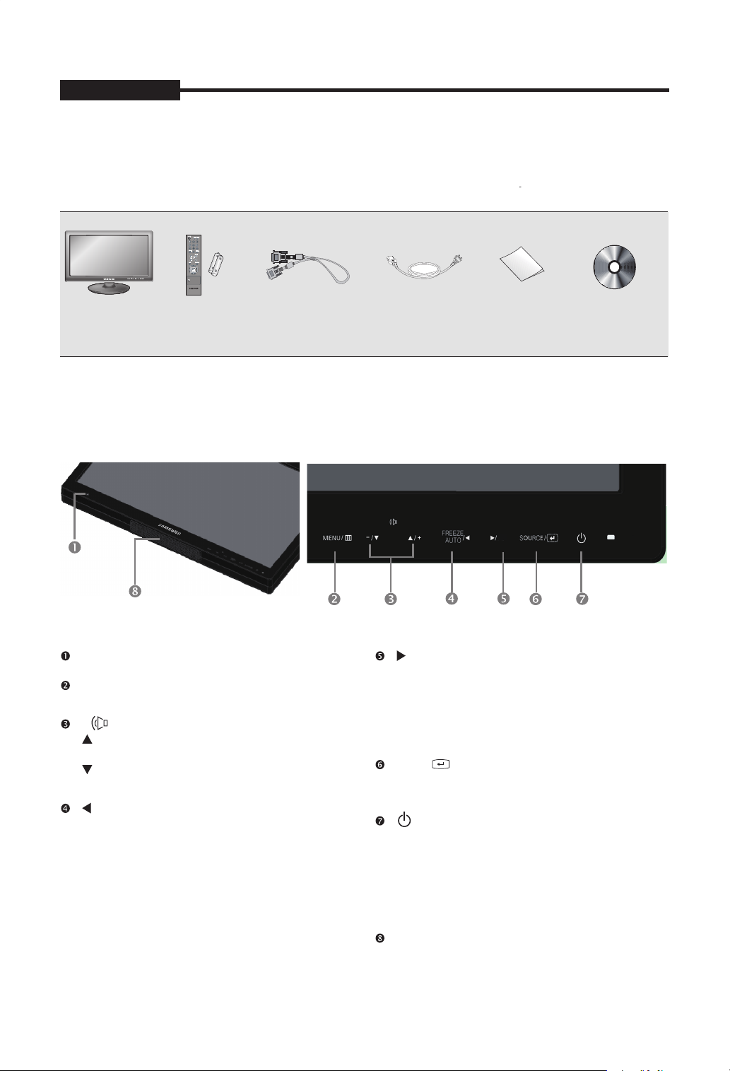
Unpacking
Remove the package cover and place the product on a flat and secure surface or in the installation location.
Check whether all the following devices and accessories are included with the main system.
The colour and the appearance may differ depending on the product
7 8 9
0
PIP/A-SWITCH
A-SWITCH
.
security-LED
MONITOR
REMOTE &
BATTERIES
VGA SIGNAL
CABLE
Viewing the Control Panels
Front View
Remote controller sensor.
MENU
Activates and exits the On Screen Display.
- +
: Moves the OSD menu or increases
the volume level.
: Moves the OSD menu or decreases
the volume level.
/ FREEZE/AUTO
Decrease the level of active function and move to
the previous menu.
Still picture function in Video mode when there
is no OSD menu on the screen.
Also, activates Auto adjustment function in the
VGA mode when you press the Auto button with
the OSD Menu off.
POWER CORD USER GUIDE USER’S MANUAL
CD
A-SWITCH
/ A-SWITCH
Increases the level of active function, and selects
OSD menu. According to the interval set in the menu,
monitor will automatically switch input signal,
Video-A -> Video-B -> VGA -> HDMI.
Auto Switch would become inactive if Auto Switch
is set as off in the menu.
ENTER / SOURCE
Selects input source, activates a highlighted
menu item.
(POWER) ON/OFF
Turns the power on or off.
There will be a few seconds delay before the
display appears.
The power LED lights with blue when the power is
turned on. The power is turned off by pressing the
power switch again and the power LED goes off.
Speaker
- 5 -
Page 6
USER'S MANUAL
USER'S MANUALUSER'S MANUAL
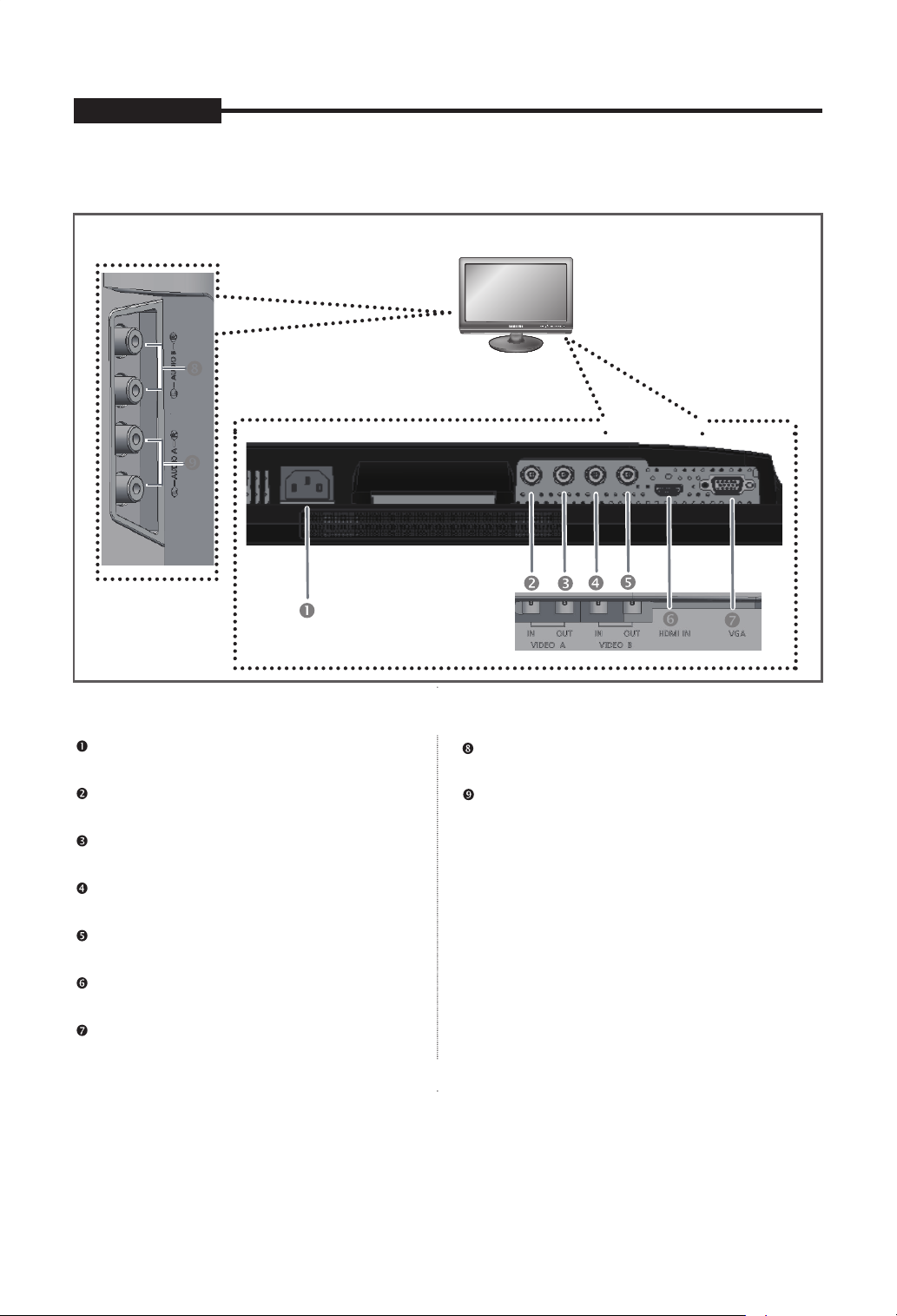
Rear & Left Side View
The colour and the appearance may differ depending on the product
Left Side View
Rear View
.
/
/
/ / /
/
Rear View
POWER
AC power input.
VIDEO-A IN
Composite signal input for VIDEO A.
Left Side View
AUDIO-B
Audio-B input : Right (RED), Left (White)
AUDIO-A
Audio-A input : Right (RED), Left (White)
VIDEO-A OUT
Video looping output for VIDEO A.
VIDEO-B IN
Composite signal input for VIDEO B.
VIDEO-B OUT
Video looping output for VIDEO B.
HDMI IN
HDMI signal input.
VGA
VGA signal input
Note
When you don’t use video looping output ,please unplug video looping output cable or connect a 75 terminal
resistance at the video looping output jack .Otherwise,it will cause the signal scope oversized which bring about
brightness distortion.
- 6 -
Ω
Page 7
USER'S MANUALUSER'S MANUAL
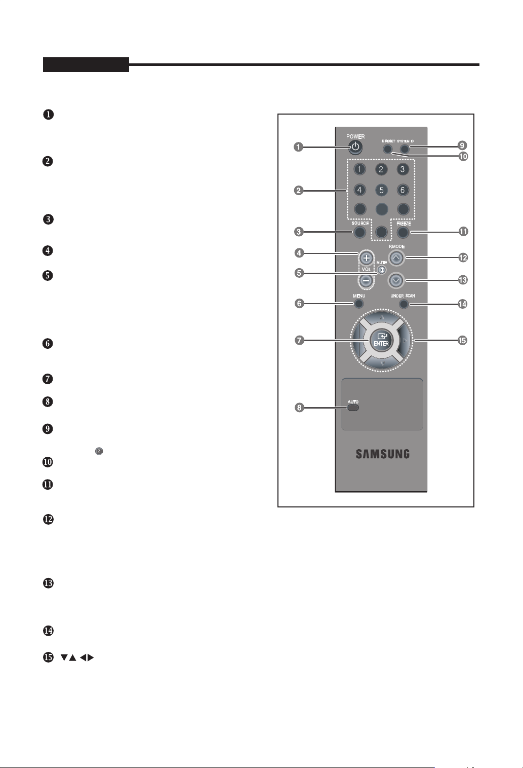
Remote Controller
POWER
Turns the Power On or Off.
There will be a few seconds delay before display
appears.
Number button
Changes the SYSTEM ID for remote controller.
With the SYSTEM ID button pressed, entered the
desired NUMBER by pressing the corresponding
button(0~9) to set up the Remote Controller ID
SOURCE
Press the 'SOURCE' button to change the input signal
source.
VOLUME +, -
Adjusts the audio volume.
MUTE
Press to mute the sound temporarily.
Displayed on the bottom left of the screen.
Press the MUTE button again to cancel the Mute
function. Alternatively press the - or + button to cancel
the Mute function.
MENU
Open the on-screen menu and exit from the menu
screen or close screen adjustment menu.
ENTER
Activates a highlighted menu item.
AUTO - Available In VGA mode Only
Adjusts the screen display automatically.
SYSTEM ID
Setting the SYSTEM ID of remote controller.
Refer to Number button.
ID RESET
Resets 1(default value) for the remote control ID.
FREEZE - Available in Video A/B,HDMI Mode
Press the button once to freeze the screen. Press it
again to unfreeze.
P.MODE
Press to select a pre-defined Picture Mode of the
required. When you press this button, current mode
The monitor has three auto matic picture settings that
again to
circle through available reconfigured modes.
monitor or to change the picture atmosphere as
is displayed on the lower center of the screen.
are preset at the factory. Then push button
( Dynamic, Standard, Movie)
PIP (Available in VGA/HDMI Mode)/A-SWITCH
Push the PIP button to turn PIP screen On/Off. (PIP is not available for SMT-1935/SMT-2233)
After pressing A-Switch button, monitor will automatically switch input signal, Video-A ->
Video-B -> VGA -> HDMI according to the interval set in the menu.
UNDER SCAN - Available in Video A/B,HDMI Mode
Displays the entire video signal on the screen.
/ buttons
Moves from one menu item to another horizontally, vertically or adjusts selected menu values.
7 8 9
0
PIP/A-SWITCH
- 7 -
Page 8
USER'S MANUAL
USER'S MANUAL
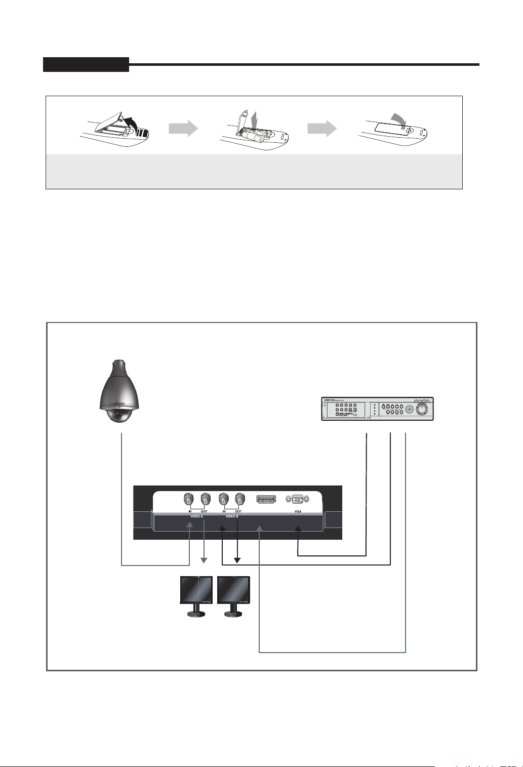
Installing batteries in the Remote Control
1. Lift the cover at the back of the remote control
upward as shown.
2. Install two AAA size batteries.
Make sure to match the “+” and “–” ends
of the batteries with the diagram inside the
compartment.
3. Replace the cover.
Assuming typical TV usage, the batteries last for
about one year.
NOTE
x
Use the remote control within 23 feet from Monitor.
Bright light may affect the performance of the remote control. Avoid
x
using nearby special fluorescent light or neon signs.
Connecting to External Devices.
The product can be connected to an external device such as Camera, DVR, External Monitor, etc.
CAMERA
DVR
External MONITOR
HDMI IN
- 8 -
Page 9

USEUSER'R'SS MAMANNUAUALL
Securing the Installation Space
Keep the required distances between the product and other objects (e.g. walls) to ensure proper ventilation.
Failing to do so may result in fire or a problem with the product due to an increase in the internal temperature of the product.
When using a stand or wall-mount, use parts provided by Samsung Techwin only.
✎
If you use parts provided by another manufacturer, it may result in a problem with the product or an injury due to the product falling.
x
✎
The appearance may differ depending on the product.
Be careful when you contact the monitor because some parts can be somewhat hot.
✎
Installation with a stand.
10 cm
10 cm
10 cm
Installation with a wall-mount.
10 cm
10 cm
10 cm
10 cm
- 9 -
Page 10

USER'S MANUAL
USER'S MANUAL
OSD Menu Configurations
No Signal Display
When there is no connection at the VGA, and Video
HDMI input, the On Screen Display will show this message.
No Signal
<Video mode>
Check signal cable
<VGA.HDMI mode>
OSD Menu Selection
1. Press the MENU button to see the main menu.
2. Press
menu.
3. Press
sub menu.
4. Press
setting. (Or press
5. Press the MENU button to exit.
NOTE1: Press the button to return to the
previous screen.
Press the MENU button to exit .
NOTE2: The OSD display will be disapear after 1
NOTE3:
/ and ENTER button to select the main
/ and ENTER (or ) button to select the
/ and ENTER (or ) button to select
/ button to select setting)
minutes if there is no button input.
The displayed image may differ depending
on the model.
1. Press the MENU button to select the
2. Press the ENTER or
3. Press the ENTER or
4. Press the
5. Press the MENU button to exit.
Picture Menu
Mode : Dynamic, Standard, Movie
The displayed image may differ depending on the
input signal.
Mode : Dynamic
Backlight
Contrast
Brightness
Sharpness
Screen
Auto
Advanced Settings
Mode :
Backlight
0
Contrast
Sharpness 50
Screen
Auto
Advanced
Picture menu.
menu.
/ and ENTER button to select the
mode you want. (Dynamic, Standard, Movie )
You can return to the factory defaults picture
settings by selecting the "Reset".
Custom : Backlight,Contrast,Brightness,
Sharpness, Colour,Tint
Mode : Dynamic
Backlight
Contrast
Brightness 45
Sharpness 50
Screen
Auto
Advanced
Picture
Adjustment
More
Move Enter Return
Picture
Dynamic
Standard
Movie
Adjustment
Settings
More
Move Enter Return
button to select the Mode
button.
Picture
Adjustment
Settings
More
Move Enter Return
10
100
45
45
10
100
50
00
1. Press the MENU button to select the Picture menu.
2. Press the ENTER or
3. Press the
/ button to select the setting you want.
button.
(Backlight,Contrast,Brightness,Sharpness,Colour,
Tint)
Press the ENTER button.
- 10 -
Page 11

USER'S MANUALUSER'S MANUAL
USER'S MANUAL
In VGA Mode, "Sharpness" can not be adjusted.
Only when the input signal is NTSC mode, can Tint
function be applicable.
Screen
Image Lock , PC Position , Image Reset
Image Lock (Coarse and Fine Tuning of the Image)
·
The purpose of picture quality adjustment is to
remove or reduce picture noise.
If the noise is not removed by Fine-tuning alone,
then adjust the frequency as best as possible
(coarse) and Fine-tune again.
After the noise has been reduced, re-adjust the
picture so that it is aligned on the center of screen.
Screen
Image Lock
PC Position
Image Reset
Move Enter Return
Image Lock
100
100
PC Position
·
Adjust the PC’s screen positioning if it does not fit
the Monitor screen.
PC Position
Move Enter Return
1. Follow the "Image Lock" instructions number
2 to 4.
2. Press the
then press
3. Press the
button to select "PC Position",
/
ENTER button.
/ button to adjust the Vertical
Position.
Press the
/ button to adjust the Horizontal
Position.
Press the ENTER button.
4. Press the MENU button to exit.
Image Reset (Initializing the Image Settings)
·
You can replace all image settings with the
factory default values.
Screen
Image Lock
PC Position
Image Reset
Move Enter Return
1. Preset: Press the SOURCE button to select VGA
mode.
2. Press the MENU button to select the
3. Press the ENTER or
4. Press the
/ and ENTER button to select the
button.
Picture menu.
Screen menu.
5. Press the
/ to select "Image Lock", then press the
ENTER button.
6. Press the
/ button to select "Coarse" or "Fine",
then press the ENTER button.
7. Press the
/ button to adjust the screen quality.
Press the ENTER button.
Press the MENU button to exit.
8.
Move Enter Return
1. Follow the "Image Lock" instructions number
2 to 4.
2. Press the
/ button to select "Image Reset",then
press the ENTER button.
Press the MENU button to exit.
3.
Only in VGA Mode, "Screen" can be adjusted.
- 11 -
Page 12

USER'S MANUAL
USER'S MANUAL
Auto Adjustment
(Adjusting the PC screen automatically)
Auto adjustment allows the PC screen of set to selfadjust to the incoming PC video signal. The values of
fine, coarse and position are adjusted automatically.
Mode : Dynamic
Backlight
Contrast
Brightness
Sharpness
Screen
Auto
Advanced Settings
Picture
Adjustment
More
Move Enter Return
10
100
45
50
1. Press the MENU button to select the Picture menu.
2. Press the ENTER or
3. Press the
/ and ENTER button to select the
button.
Auto Adjustment menu.
4.
It will be adjusted automatically
5. Press the MENU button to exit.
PC screen can be adjusted
automatically by pressing
AUTO button on the remote
control.
* Only in VGA Mode, "Auto Adjustment" can be available.
Advanced Settings
Gamma, White Balance
Mode : Dynamic
Backlight
Contrast
Brightness
Sharpness
Screen
Auto
Advanced Settings
Picture
Adjustment
More
Move Enter Return
10
100
45
50
10. Press the MENU button to exit.
White Balance
R-Offset
G-Offset
B-Offset
R-Gain
G-Gain
B-Gain
Reset
1. Press the MENU
Move Enter Return
button to select the
25
25
25
25
25
25
Picture menu.
2. Press the ENTER or
3. Press the
Advanced Settings menu .
the
and ENTER button to select
/
4
/
Press the
setting value and save of the Gamma menu.
the
and the ENTER
button.
button two times. Press the ENTER or
button to adjust
5. Select the White Balance menu and then
press the ENTER or button.
6. It includes:R-Offset,G-Offset,B-Offset,R-Gain,
G-Gain,B-Gain and Reset.
menus in turn by pressing button.
Press the ENTER or
7.
menu:R-Offset,G-Offset,B-Offset,R-Gain,
the
Select these
/
button when selecting
G-Gain,B-Gain.
8.
Press the
adjust the
9.
Press Reset menu, the menu R-Offset,G-Offset,
/
and the ENTER
button to
setting value and save.
B-offset,R-Gain,G-Gain,B-Gain will return back to
the default value 25.
Gamma
Adjust
0
Return
- 12-
Page 13

USER'S MANUAL
USER'S MANUAL
Picture Options: Colour Tone/Size/
Digital NR/HDMI Black Level
Picture Options
Colour Tone :
Size :
Digital NR : Auto
HDMI Black Level
Cool
Normal
Warm1
Warm2
: Normal
Reset
You can return to the factory defaults picture settings.
Picture
More
Picture Options
Reset :
OK
Cancel
Move Enter Return
Size
16:9
Zoom
4:3
Under Scan
Move Enter Return
1. Press the MENU
button to select the Picture
menu.
2. Press the ENTER or
3. Press the
/
button.
and ENTER button to select the
Picture Options menu .
4. There are 4 sub menu: Colour Tone,Size,
Digital NR,HDMI Black Level.
5. Press the ENTER or
button.
Select the mode of Colour Tone: Cool,Normal,
Warm1, Warm2 by pressing
/
button and
ENTER button.
6. Select the Size menu,you can adjust picture
in turn by 16:9,Zoom,4:3,Under Scan.
SMT-1935: Under Scan and 16:9 are not available
in VGA mode.
SMT-2233/SMT-1931/SMT-2731: Under Scan is
not available in VGA mode. When the input
signal is PAL, Under Scan is not available In
Video-A & Video-B mode,
7.
The Digital NR menu includes :
Off, Low, Medium,
High,Auto.
Digital NR is not available in VGA mode.
The HDMI Black Level menu includes : Normal, Low.
8.
Only in the HDMI mode, the menu HDMI Black
Level can be adjusted. Its default value is Normal.
Move Enter Return
1. Press the MENU button to select the
Picture menu.
2. Press the ENTER or
3. Press the
/ and ENTER button to select the
button.
Reset menu .
4. Press the
/ button to select "OK" or "Cancel".
Press the ENTER button.
5. Press the MENU button to exit.
In VGA/HDMI mode,the picture menu will display
resolution information .
Sound Menu
Mode: Standard,Music,Movie,Clear Voice,Custom
Sound
Mode : Custom
Equalizer
Reset
Move Enter Return
Sound
Mode :
Equalizer
Move Enter Return
1. Press the MENU and
Sound menu.
2. Press the ENTER or
to select the
3.
Press the
Mode menu.
/ and ENTER button to select the
button two times
setting you want.
4.
Press the MENU button to exit.
Standard
Music
Movie
Off Reset
:
Clear Voice
Custom
/ button to select the
- 13 -
Page 14

USER'S MANUAL
USER'S MANUAL
Equalizer
Sound
Mode : Custom
Equalizer
Reset
Move Enter Return
Equalizer
Bala nce 100Hz 300Hz 1kHz 3kHz 10kHz
Move Adjust Return
1. Press the MENU and / button to select the
Sound menu.
2. Press the ENTER or
3. Press the
/ and ENTER button to select the
button.
Equalizer menu.
4. Press the
/ button to select a particular item.
Press the ENTER button.
5. Press the
/ and ENTER button to adjust the
setting value and save .
6. Press the MENU button to exit.
If you make any changes to these settings, the
Sound Mode is automatically switched to "Custom".
Reset
Selecting the Reset function after setting the equalizer
resets the equalizer setting to the factory defaults.
Sound
Mode : Custom
Equalizer
Reset
Setup Menu
Language
Language : English
Blue Screen : Off
Melody :
ECO Saving :
Auto Switch
System ID : 1
No Signal OSD : On
Screen Burn Protection
Language :
Blue Screen :
Melody :
ECO Saving :
Auto Switch
System ID :
No Signal OSD :
Screen Burn Protection
1. Press the MENU and / button to select the
Setup menu.
2. Press the ENTER or
3. Press the
/ and ENTER button to select the
Language menu.
4. Press the
/ and ENTER button to select the
setting you want.
5. Press the MENU button to exit.
Blue Screen/Melody
Language : English
Blue Screen :
Melody :
ECO Saving : Off
System ID : 1
No Signal OSD : On
Screen Burn Protection
Setup
Off
Off
Off :
Move Enter Return
Setup
English
Français
Español
Move Enter Return
Português
한국어
:
日本語
Deutsch
Italiano
button.
Setup
: Off
Off
On
Move Enter Return
1. Press the MENU and
/ button to select the
Sound menu.
2. Press the ENTER or
3. Press the
/ and ENTER button to select the Reset.
button.
4. Press the MENU button to exit.
You can select the “Reset” function only when the
sound “Mode” is set to “Custom”.
1. Press the MENU and
Setup menu.
2. Press the ENTER or
- 14 -
Move Enter Return
Language : English
Blue Screen : Off
Melody :
ECO Saving :
Auto Switch
System ID : 1
No Signal OSD : On
Screen Burn Protection
Setup
Off
Move Enter Return
Low
Medium
High
/ button to select the
button.
Page 15

USER'S MANUAL
3. Press the / and ENTER button to select the
Blue Screen or Melody menu.
4. Press the
/ and ENTER button to select the
setting you want.
Blue Screen: Off/On
·
If no signal is being received or the signal is very weak,
a blue screen automatically replaces the noisy picture
background. If you wish to continue viewing the poor
picture, you must set the "Blue Screen" mode to "Off".
In HDMI Mode, "Blue Screen" can not be adjusted.
Melody: Off/Low/Medium/High
·
You can hear melody sound when the monitor is
powered on or off.
You can hear the melody when the monitor is
turned on even if you turn the volume down to zero.
5. Press the MENU button to exit.
ECO Saving
Setup
Language : English
Blue Screen : Off
Melody
ECO Saving
Auto Switch
System ID : 1
No Signal OSD : On
Screen Burn Protection
Move Enter Return
Language : English
Blue Screen : Off
Melody
ECO Saving
Auto Switch
System ID : 1
No Signal OSD : On
Screen Burn Protection
Setup
: Off
: Off
Off
75%
50%
Auto Switch
Setup
Language : English
Blue Screen : Off
Melody
ECO Saving
Auto Switch
System ID : 1
No Signal OSD : On
Screen Burn Protection
Move Enter Return
Language : English
Blue Screen : Off
Melody
ECO Saving
Auto Switch
System ID : 1
No Signal OSD : On
Screen Burn Protection
Move Enter Return
Setup
: Off
: Off
: Off
Off
5 sec
10 sec
20 sec
30 sec
60 sec
When you configure Auto Switch, monitor will
automatically switch input signal Video-A ->
Video-B -> VGA -> HDMI according to the time interval
you set in the menu.
1. Press the MENU and
/ button to select the
Setup menu.
2. Press the ENTER or
3. Press the and ENTER button to select
/
button.
Auto Switch menu.
4. Press the and ENTER buttons to set Time Interval.
/
Setting up Your PC Software
(Based on Windows XP)
Move Enter Return
This function adjusts the brightness of the Monitor
so as to reduce power consumption. When watching
Monitor at night, set the"Energy Saving" mode option
to "High" to reduce eye fatigue as well as power
consumption.
: Change the monitor power consum
75%
ption to 75%
of the default level.
: Change the monitor power consum
50%
ption to 50%
of the default level.
: Deactivate the Eco Saving function.
Off
1. Press the MENU and
/ button to select the
Setup menu.
2. Press the ENTER or
3. Press the
/ and ENTER button to select the
button.
Energy Saving menu.
4. Press the
/ and ENTER button to select the
setting you want.
5. Press the MENU button to exit.
The Windows Display Properies for a typical
computer are shown above. The actual screens
on your PC may be different depending upon
your particular version of Windows and your
particular video card. Even if your actual screens
look different, the same, basic set-up information
will apply in almost all cases. (If not, contact your
computer manufacturer or Samsung Dealer.)
- 15 -
Page 16

USER'S MANUAL
1024×768
1280×720
1280x1024
USER'S MANUAL
1. First, click on "Control Panel" on the Windows start
menu.
2. When the control panel window appears, click on
"Display" and a Display Properies window will
appear.
3. Click on "Setting" .
Navigate to the "Screen resolution" tab on the
4.
Setting window.
The correct size setting (resolution):
Optimum- SMT-2233/SMT-2731: 1920 x 1080
SMT-1935: 1280 x 1024
SMT-1931: 1366 x 768
If a verti
cal-frequency option exists on your Settings
window, the correct value is "60Hz" or "75 Hz".
Otherwise, just click "OK" and exit the window.
Display Modes
Both screen position and size will vary depending
on the type of monitor and its resolution.
The resolutions in the table are recommended. (All
resolutions between the supported limits are
supported.)
SMT-2233
Display Mode
IBM
VESA DMT
MAC
VESA DMT
IBM
DTV CEA
VESA DMT
VESA DMT
MAC
VESA DMT
VESA DMT
VESA GTF
VESA CVT
VESA
VESA
VESA
VESA
VESA
Refresh
Rate
640×350
640×480
640×480
640×480
720×400
720×576
800×600
800×600
832×624
1024×768
1280×720
1152x720
1280x960
1600x1200 75.000 60.000
1920x1080 67.432 59.94
(Hz)
70
60
67
72
75
70
60
60
72
75
75
60
70
75
60
70
75
75
60
60
75
60
65
70
60
Horizontal
Frequency
(kHz)
31.469
31.469
37.861
37.500
31.469
35.91
37.879
48.077
46.875
49.726
48.363
56.476
60.023
44.772
52.53
56.456
67.500
60.000 60.000
63.979 60.000
79.972 75.024
81.25 65.000
87.500 70.000
Frequency
35
Vertical
(Hz)
70.086
59.94
66.667
72.809
75.000
70.087
59.95
60.317
72.188
75.000
74.551
60.004
70.069
75.029
59.855
69.853
74.777
75.000
SMT-1935
Display Mode
IBM
640×350
720×400
640×480
VESA
MAC
640×480
640×480
800×600
800×600
800×600
1024×768
1024×768
1024×768
1152×864
1280×960
1280x1024
1280×1024
640×480
832x624
1152x870
SMT-1931
Horizontal
Frequency
(kHz) (Hz)
31.469
31.469
31.469
37.861
37.500
37.879
48.077
46.875
48.363
56.476
60.023
67.500
60.000
63.981
79.976
35.000
49.726
68.681
Vertical
Frequency
70.086
70.087
59.940
72.809
75.000
60.317
72.188
75.000
60.004
70.069
75.029
75.000
60.000
60.020
75.025
66.667
74.551
75.062
Pixel Clock
(MHz)
25.175
28.322
25.175
31.500
31.500
40.000
50.000
49.500
65.000
75.000
78.750
108.000
108.000
108.000
135.000
30.240
57.284
100.000
Sync
Polarity
(H/V)
+/-
-/+
-/-
-/-
-/-
+/+
+/+
+/+
-/-
-/-
+ /+
+/+
+/+
+/+
+/+
-/-
-/-
+/+
- 16 -
Page 17

USER'S MANUAL
SMT-2731
Display Mode
IBM 640 x 350 70 31.469 70.086
VESA DMT 640 x 480 60 31.469 59.94
MAC 640 x 480 67 35 66.667
VESA DMT 640 x 480
IBM 720 x 400 70 31.469 70.087
DTV CEA 720 x 400 85 37.927 85.038
VESA DMT 800 x 600 60 37.879 60.317
VESA DMT 800 x 600
MAC 832×624 75 49.726 74.551
VESA DMT 1024×768
VESA GTF
1280×720 60 45.00 60.00
1280×720 60 44.772 59.855
VESA 1152×864 75 67.5 75.00
VESA 1280×960 60 60.000 60.000
VESA 1280×1024
VESA 1600×1200
VESA 1920×1080
Refresh
Rate (Hz)
72 37.861 72.809
75 37.500 75.000
72 48.077 72.188
75 46.875 75.000
60 48.363 60.004
70 56.476 70.069
60 63.979 60.000
75 79.972 75.024
60 75.000 60.000
65 81.25 65.000
70 87.500 70.000
60 67.158 59.963
60 67.500 60.00
The interlace mode is not supported.
The set might operate abnormally if a non-standard
video format is selected.
Separate and Composite modes are supported.
SOG is not supported.
Horizontal
Frequency(KHz)
Vertical
Frequency(Hz)
System ID
Language : English
Blue Screen : Off
Melody
ECO Saving
Auto Switch
System ID
No Signal OSD : On
Screen Burn Protection
1. Press the MENU and / button to select the
Setup menu.
2. Press the ENTER or
Press the
3.
4.
Press the / and ENTER button to select the
/ button to select the System ID.
setting you want .(0~9)
5. Press the MENU button to exit.
Setup
Move Enter Return
: Off
:
1
button.
0
1
2
3
4
No Signal OSD
No Signal OSD determines whether “No Signal” displays
on the screen or not.
If you set the No Signal OSD to On, the screen will dis-
plays “No Signal” when there is no video signal input.
If you set the No Signal OSD to Off, the screen will not
display “No Signal” when there is no video signal input.
Setup
Language : English
Blue Screen : Off
Melody
ECO Saving
Auto Switch
System ID : 1
No Signal OSD : On
Screen Burn Protection
Move Enter Return
: Off
: Off
1. Press the MENU and / button to select the
Setup menu.
2. Press the ENTER or
3. Press the
4. Press the
/ button to select the No Signal OSD.
/ and ENTER button to select the
button.
setting you want .
5. Press the MENU button to exit.
This function is not available in VGA and HDMI mode.
Screen Burn Protection
To reduce the possibility of screen burn, this unit is
equipped with Screen Burn Protection screen burn
prevention technology.
Screen Burn Protection moves the picture slightly
on the screen.
The Screen Burn Protection setting allows you to
programme the time between movements of the picture
in minutes.
- 17 -
Page 18

USER'S MANUAL
Setup
Language : English
Blue Screen : Off
Melody
ECO Saving
Auto Switch
System ID : 1
Screen Burn Protection
Move Enter Return
Screen Burn Protection
Screen Burn Protection
Interval
Mode : Mode 1
Move Enter Return
: Off
:
Off
: On No Signal OSD
: On
: 4 Hours
1. Press the MENU and / button to select the
Setup menu.
2.
Press the ENTER or
Press the / button to select Screen Burn
3.
button.
Protection.
4. Press the / and ENTER button to select the
setting you want .
5. Press the MENU button to exit.
Interval: You can set the interval for Screen Burn Protection.
The Screen Burn Protection feature stops automatically
after a specified period of time.
Mode 1: Pixels on the screen moves from Top to the
bottom, left to the right.
Mode 2:
A vertical bar moves left to right.
Mode 3: Fading screen. The entire screen becomes
brighter, then darker.
Input Menu
Source List
Input
Source List : Video A
Edit Name
Move Enter Return
Input
Video A : – – – –
Video B : – – – –
VGA
: – – – –
HDMI
Move Enter Return
: – – – –
1. Press the MENU and / button to select Input
menu.
2. Press the ENTER and button.
3.
Press the / and ENTER button to select the
Source List.
4.
Press the / and ENTER button to select desired
source.
5. Press the MENU button to exit.
Press the SOURCE button on the remote control
to toggle between all the available source.
Edit Name
Source List : Video A
Edit Name
Video A :
Video B :
VGA
HDMI
1. Press the MENU and / button to select Input
menu.
2. Press the ENTER and
3. Press the
/ and ENTER button to select the
Edit Name.
4. Press the
5. Press the
/ and ENTER button to select the input.
/ button to select the name you want.
Press the ENTER button.
6. Press the MENU button to exit.
Input
Move Enter Return
Edit Name
:
Move Enter Return
----
VCR
DVD
Cable STB
:
Satellite STB
PVR STB
AV Receiver
Game
button.
- 18 -
Page 19

USER'S MANUAL
Specifications (SMT-2233/SMT-1935)
Model name SMT-2233 SMT-1935
Sales Area
Broadcasting System
Inch
22''
Display Type LED PANEL
Resolution (HxV) 1920 X 1080 1280 x 1024
Panel
Brightness (cd/m²) 250
Contrast 1000:1
Response Time 5msec
Viewing Angle Degree 170(Horizontal)/160(Vertical)
Pixel Pitch(mm)
0.248(H)x 0.248(V) 0.294(H)x 0.294(V)
Scan System
CVBS Resolution
Scanning Frequency
Color System
Picture
Screen Mode
3D Comb Filter
Noise Reduction
Auto Switch
Freeze
Under Scan
Composite 2CH input, 1.0Vp-p,75Ωterminal,Loop Through
Video
HDMI 1CH input
out,BNC Type
VGA 1CH input
Audio
OSD language
2 Channel input,2W Stereo,RCA Type
16 languages(Eng/Fre/Ger/Spa/Ita/Por/Dut/Swe/
Rus/Tha/Ara/Tur/Dan/Kor/Jpn/Chi)
Simple Stand Tilt -2° ~22°
515mm x 217.4mm x 391.8mm
Dimensions
(WxDxH)
Net
(with stand)
515mm x 59.9mm x 316mm
(without stand)
Weight Net weight 5.18Kg 4.78Kg
Electric Performance
Operating condition
Power Supply AC 100~240V
Power Consumption 24W 22W
Temperature
Humidity
20%-90%(non-condensation)
NTSC/PAL System
Progressive
NTSC: 600TVL, PAL: 620TVL
Horizontal: 30KHz-81KHz
Vertical:56Hz-75Hz
NTSC 3.58/PAL 4.43
4:3, 16:9
0℃ ~+40℃°
Worldwide
19''
Yes
Yes
Yes
Yes
Yes
412mm x 217.4mm x 406.5mm
(with stand)
412mm x 59.4mm x 347mm
(without stand)
- 19 -
Page 20

USER'S MANUAL
Specifications (SMT-2731/SMT-1931)
Model name SMT-2731 SMT-1931
Sales Area
Broadcasting System
Inch 27''
Display Type LED PANEL
Resolution (HxV) 1920 X 1080 1366 x 768
Panel
Picture
Video
OSD language
Simple Stand Tilt -2° ~22°
Dimensions
(WxDxH)
Weight Net weight 7.28Kg 4.23Kg
Electric Performance
Operating condition
Brightness (cd/m²) 300 250
Contrast
Response Time
Viewing Angle Degree
Pixel Pitch(mm)
Scan System
CVBS Resolution
Scanning Frequency
Color System
Screen Mode
3D Comb Filter
Noise Reduction
Auto Switch
Freeze
Under Scan
Composite 2CH input, 1.0Vp-p,75Ωterminal,Loop Through
HDMI 1CH input
VGA 1CH input
Audio
Net
Power Supply AC 100~240V
Power Consumption 39.5W 18.5W
Temperature
Humidity
0.248(H)x 0.248(V) 0.300(H)x 0.300(V)
Horizontal: 30KHz-81KHz
Vertical:47Hz-75Hz
out,BNC Type
16 languages(Eng/Fre/Ger/Spa/Ita/Por/Dut/Swe/Rus/
Tha/Ara/Tur/Dan/Kor/Jpn/Chi)
648mm x 479.1mm x 212mm
(with stand)
648mm x 396mm x 61.66mm
(without stand)
170(Horizontal)/160(Vertical)
NTSC: 600TVL, PAL: 620TVL
2 Channel input,2W Stereo,RCA Type
20%-90%(non-condensation)
Worldwide
NTSC/PAL System
1000:1
5msec
Progressive
Horizontal: 30KHz-81KHz
NTSC 3.58/PAL 4.43
4:3, 16:9
Yes
Yes
Yes
Yes
Yes
446.4mm x 359.6mm x 217.4mm
(with stand)
446.4mm x 59.4mm x 276.9mm
(without stand)
0℃ ~+40℃°
19''
Vertical:56Hz-75Hz
- 20 -
Page 21

USER'S MANUAL
Dimensions
SMT-2233
18,6
269,3
103,9
515
477,8
316
391,8
61,9
Unit:mm
59,9
217,4
- 21 -
Page 22

USER'S MANUAL
Dimensions
SMT-1931
Unit:mm
- 22
-
Page 23

USER'S MANUAL
Dimensions
SMT-1935
17.4
302.1
87
412
377.3
347
406.5
Unit:mm
59.4
217.4
63.1
- 23-
Page 24

USER'S MANUAL
Dimensions
SMT-2731
Unit:mm
- 2
4 -
Page 25

USER'S MANUAL
Correct Disposal
Correct Disposal of This Product (Waste Electrical & Electronic Equipment)
(Applicable in the European Union and other European countries with separate
collection systems)
This marking on the product, accessories or literature indicates that the product and its
electronic accessories (e.g. charger, headset, USB cable) should not be disposed of
with other household waste at the end of their working life. To prevent possible harm to
the environment or human health from uncontrolled waste disposal, please separate
these items from other types of waste and recycle them responsibly to promote the
sustainable reuse of material resources.
Household users should contact either the retailer where they purchased this product,
or their local government office, for details of where and how they
for environmentally safe recycling.
can take these items
Business users should contact their supplier and check the terms and conditions of the
purchase contract. This product and its electronic accessories should not be mixed with
other commercial wastes for disposal.
- 25 -
Page 26

SALES NETWORK
HEAD OFFICE
6, Pangyo-ro 319beon-gil, Bundang-gu, Seongnam-si, Gyeonggi-do, SEOUL 463-400 Rep. of KOREA
Tel : +82-70-7147-8753, 8764 Fax : +82-31-8018-3740
www.samsungsecurity.com
SAMSUNG TECHWIN AMERICA Inc.
100 Challenger Rd. Suite 700 Ridgefield Park, NJ 07660
Toll Free : +1-877-213-1222 Direct : +1-201-325-6920
Fax : +1-201-373-0124
www.samsung-security.com
www.samsungsecurity.com
www.samsungipolis.com
SAMSUNG TECHWIN EUROPE LTD.
2nd Floor, No. 5 The Heights, Brooklands, Weybridge,
Surrey, KT13 0NY, UK
Tel : +44-1932-82-6700 Fax : +44-1932-82-6701
www.samsungsecurity.co.uk
 Loading...