

Samsung SMO-210TRP User Manual

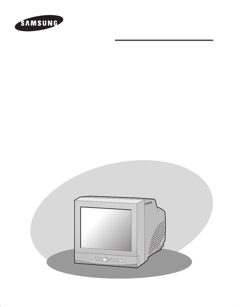
COLOR MONITOR
SMO-150TRN(P)
SMO-210TRN(P)
User Guide
Mode d’emploi
Bedienungsanleitung
Manuale dell'utente
Guía del usuario
Gebruikershandleiding
Manual do utilizador
Brugervejledning
Användarhandbok
уководство пользователя
Graphic Symbol Explanation
The lightning flash with arrowhead symbol, within an
equilateral triangle, is intended to alert the user to the
presence of uninsulated “dangerous voltage” within the
product’s enclosure that may be of sufficient magnitude to constitute a risk of electric shock to persons.
The exclamation point within an equilateral triangle is intended to alert
the user to the presence of important operating and
maintenance (servicing) instructions in the literature
accompanying the appliance.
Warning-To Prevent Fire or Shock
Hazard,
Do Not Expose This Equipment To Rain or
Moisture.
IMPORTANT SAFEGUARDS
Caution
Power source is indicated on the rear of the set. It contains high-voltage parts. If you remove the cover, it may cause fire or electric shock.
Do not remove the cover by yourself. (Control switches are at the
front of the monitor.)
1. Read instructions: All the safety and operating instructions should be
read before the appliance is operated.
2. Retain instructions: The safety and operating instructions should be
retained for future reference.
3. Heed warnings: All warnings on the appliance and in the operating
instructions should be adhered to.
4. Follow instructions: All operating and use instructions should be followed.
5. Cleaning: Unplug this video product from the wall outlet before
cleaning. Do not use liquid cleaners or aerosolcleaners. Use a damp
cloth for cleaning.
Exception. A monitor that is meant for uninterrupted service and that
for some specific reason, such as the possibility of the loss of an
authorization code for a CATV converter, is not intended to be
unplugged by the user for cleaning or any other purpose, may exclude
the reference to unplugging the monitor in the cleaning description
otherwise required in Item 5.
6. Attachments: Do not use attachments not recommended by the video
product manufacturer as they may cause hazards.
7. Water and moisture: Do not use this video product near water - for
example, near a bath tub, wash bowl, kitchen sink, or laundry tub, in a
wet basement, or near a swimming pool, and the like.
8. Accessories: Do not place this monitor on an unstable cart, stand, tripod, bracket, or table. The monitor may fall, causing serious injury to
a child or adult, and serious damage to the appliance. Use only with a
cart, stand, tripod. bracket, or table recommended by Samsung, or
sold with the monitor. Any mounting of the monitor should follow
Samsung’s instructions, and should use a mounting accessory recommended by Samsung.
9. Ventilation: Slots and openings in the cabinet are provided for ventilation and to ensure reliable operation of the monitor and to protect it
from overheating, and these openings should never be blocked by
placing the monitor on a bed, sofa, rug, or other similar surface. This
monitor should never be placed near or over a radiator or heat register.
This monitor should not be placed in a built-in installation such as a
bookcase or rack unless proper ventilation is provided or Samsung’s
instructions have been adhered to.
10. Power Sources: This monitor should be operated only from the type
of power source indicated on the making label. If you are not sure of
the type of power supply to your installation site, consult your
Samsung dealer or local power company.
11. Grounding or Polarization: For monitors equipped with a 3-wire
grounding-type plug having a third(grounding) pin. This plug will
only fit into a grounding type power outlet. This is a safety feature. If
you are unable to insert the plug into the outlet, contact your electrician to replace your obsolete outlet. Do not defeat the safety purpose
of the grounding-type plug.
12. Power: Cord Protection-Power supply cords should be routed so that
they are not likely to be walked on or pinched by items placed upon
or against them, paying particular attention to cords at plugs, convenience receptacles, and the point where they exit from the monitor.
13. Lightning: For added protection for this monitor during a lightning
storm, or when it is left unattended and unused for long periods of
time, unplug it from the wall outlet and disconnect the cable system.
This will prevent damage to the monitor due to lightning and powerline surges.
14. Overloading: Do not overload wall outlets and extension cords as
this can result in a risk of fire of electric shock.
15. Object and liquid Entry: Never push objects of any kind into this
monitor through openings as they may touch dangerous voltage
points or short-out parts that could result in a fire or electric shock.
16. Servicing: Do not attempt to service this monitor yourself as open-
ing or removing cover may expose you to dangerous voltage or other
hazards. Refer all servicing to qualified service personnel.
17. Damage Requiring Service: Unplug this monitor from the wall out-
let and refer servicing to qualified service personnel under the following conditions.
a. When the power-supply cord or plug is damaged.
b. If liquid has been spilled, or objects have fallen into the monitor.
c. If the monitor has been exposed to rain or water.
d. If the monitor does not operate normally by following the operat-
ing instructions. Adjust only those controls that are covered by the
operating instructions as an improper adjustment of other controls
may result in damage and require extensive work by a qualified
technician to restore the monitor to its normal operation.
e. If the monitor has been dropped or the cabinet has been damaged.
f. When the monitor exhibits a distinct change in performance-this
indicates a need for service.
18. Replacement Parts: When replacement parts are required, be sure
the service technician has used replacement parts specified by
Samsung or have the same characteristics as the original parts.
Unauthorized substitutions may result in fire, electric shock or other
hazards.
19. Safety Check: Upon completion of any service or repairs to this
monitor, ask the service technician to preform safety checks to determine that the monitor is in proper operating condition.
Eng-2
CAUTION : TO REDUCE THE RISK OF ELECTRIC
SHOCK, DO NOT REMOVE COVER
(OR BACK). NO USER SERVICEABLE
PAR TS INSIDE. REFER SERVICING TO
QUALIFIED SERVICE PERSONNEL.
RISK OF ELECTRIC
SHOCK DO NOT OPEN
CAUTION

FCC & ICES Information
Warning
This equipment has been tested and found to comply the limits for a class
Adigital device, pursuant to part 15 of the FCC Rules and ICES-003 of
Industry Canada. These limits are designed to provide reasonable protection against harmful interference when the equipment is operated in a
commercial environment. This equipment generate, uses, and can radiate
radio frequency energy and, if not installed and used in accordance with
the instruction manual, may cause harmful interference to radio communications. Operation of this equipment in a residential area is likely to
cause harmful interference in which case the user will be required to correct the interference at his own expense.
User-Installer Caution
Your authority to operate this FCC verified equipment could be voided if
you make changes or modifications not expressly approved by the party
responsible for compliance to part 15 of the FCC Rules.
Information to user
Changes or modifications not expressly approved by the party responsible for compliance could void the user's authority to operate the equipment.
NOTE: This equipment has been tested and found to comply with the
limits for a Class A digital device, pursuant to Part 15 of the FCC Rules.
These limits are designed to provide reasonable protection against harmful interference when the equipment is operated in a commercial environment. This equipment generates, uses, and can radiate radio frequency
energy and, if not installed and used in accordance with the instruction
manual, may cause harmful interference to radio communications.
Operation of this equipment in a residential area is likely to cause harmful interference in which case the user will be required to correct the
interference at his own expense.
This device complies with Part 15 of the FCC Rules. Operation is subject
to the following two conditions: (1) this device may not cause harmful
interference, and (2) this device must accept any interference received,
including interference that may cause undesired operation.
Changes or modifications not expressly approved by the party responsible for compliance could void the user's authority to operate the equipment. If necessary, consult your dealer or an experienced radio/television
technician for additional suggestions. You may find the booklet called
How to Identify and Resolve Radio/TV Interference Problems helpful.
This booklet was prepared by the Federal Communications Commission.
It is available from the U.S. Government Printing Office,
Washington, DC 20402, Stock Number 004-000-00345-4.
The party responsible for product compliance:
SAMSUNG ELECTRONICS CO., LTD.
America QA Lab of Samsung
3351 Michelson Drive,
Suite #290, Irvine, CA92612 USA
IC Compliance Notice
This Class (A) digital apparatus meets all requirements of the Canadian
Interference-Causing Equipment Regulations.
Cet appareil numérique de la classe (A) respecte toutes les exigences du
Règlement sur le matériel brouilleur du Canada.
This Class A digital apparatus complies with Canadian ICES-003.
Cet appareil numéique de la classe A est conforme à la norme NMB-003
du Canada.
Warning
This is a class A product. In a domestic environment this product may
cause radio interference in which case the user may be required to take
adequate measures.
Contents
IMPORTANT SAFEGUARDS ..................................................2
FCC &ICES Information ..........................................................3
Chapter 1: Overview ...................................................................4
Overview.................................................................................4
Functions and Features ...........................................................4
Names and Functions of Partse ..............................................5
Chapter 2: Installation .................................................................6
Installation Environments.......................................................6
Unpacking...............................................................................6
Chapter 3: Basic Connecting to External Devices.....................6
1. Connecting to Time Lapse VCR (or Normal VCR).........6
2. Connecting the Alarm Sensor............................................6
3. Connecting the Door Bell Box ..........................................6
4. Connecting the Ordinary monitor......................................7
Chapter 4: Basic Operation ........................................................7
1. Basic Operation .................................................................7
2. When you want to watch on LIVE/P.B./TRIPLEX
screen. ................................................................................7
3. When you want to watch in Full Screen Mode.................7
4. When you want to watch in Sequence Screen Mode........7
5. When you want to watch in FREEZE Screen Mode.........7
6. When you want to watch in FREEZE Screen Mode.........8
7. When you want to watch on PIP Screen Mode.................8
8. When you want to watch the VCR output.........................8
9. When you want to watch the Event Replay screen...........8
10. When you want to watch a Door Bell screen..................8
Chapter 5: Setup Menu Settings ................................................9
1. VIEW SETTING ...............................................................9
2. CLOCK/DISPLAY SET....................................................9
3. CAMERA SETUP.............................................................10
4. SYSTEM SETTING..........................................................12
5. EVENT LIST.....................................................................14
6. DOOR BELL LIST............................................................14
Chapter 6: Recording ...................................................................14
1. Recording in Time Lapse (or Normal)Mode.....................14
2. Alarm/Motion Channel Intensive Recording.....................14
Chapter 7: Alarm,Motion,Loss and Door Bell...........................14
1. Alarm Occurrence..............................................................14
2. Motion Occurrence ...........................................................15
3. Loss Occurrence ................................................................15
4. Door Bell Occurrence........................................................16
Appendix........................................................................................16
Specifications..........................................................................16
Troubleshooting ......................................................................17
Eng-3
Chapter 1: Overview
Overview
The product is a triplex that enables you to record the signals
received from up to 8 cameras to a single VCR. You can record those
signals sequentially by frame or intermittently, and playback a specific channel selectively. You can use three monitor screen modes, LIVE
Mode, P.B. Mode, and LIVE + P.B. Mode, on a single monitor.
Functions and Features
• Set various functions using the Menu buttons.
• Connect up to 8 cameras for color or black-and-white pictures.
• Watch the input from up to 8 cameras on one screen in the various
split display modes.
• Watch the Live screen and the Playback screen simultaneously on
the same monitor.
• Enlarge a screen up to 2 Xs using the Zoom function.
• Utilize the Motion Detect function embedded in a camera.
• Monitor a specific screen within the main screen by using the Spot
Display function.
• Watch the Main screen simultaneously on an additional monitor
using the Slave Display function.
• Watch desired screens in still mode using the Freeze function.
• Switch and watch channels sequentially in Sequence mode.
• Hide the screens being displayed using the Hidden Camera function.
• The system has Date, Time and Alarm indicators that can be reset.
• When an Alarm occurs, the word "EVENT" is displayed on the
screen and a warning buzzer sounds. When this occurs, you can
press Enter and up to 16 frames before and after the generated
alarm will be replayed on the Event Replay window. Alarm histories are recorded in the EVENT LIST. The Alarm function is available only when the Alarm Box is connected.
• If the Channel Loss Detection function detects any channel loss,
the word "EVENT" is displayed on the screen and a warning
buzzer sounds. When this occurs, you can press ENTER and up to
16 frames before the detected chancel loss will be replayed on the
Event Replay window. Channel Loss histories are recorded in the
EVENT LIST.
• Due to the Door Bell Interlock Function, when the door bell is
pressed, the current picture switches to the doorbell area monitoring picture, in full screen mode, along with an alarming beep. At
this time, one Instant Picture is stored in the “DOOR BELL LIST”.
Up to 8 pictures can be stored in the “DOOR BELL LIST” You can
access any stored picture to be displayed on the screen. The Door
Bell Function is only available with a door bell connection.
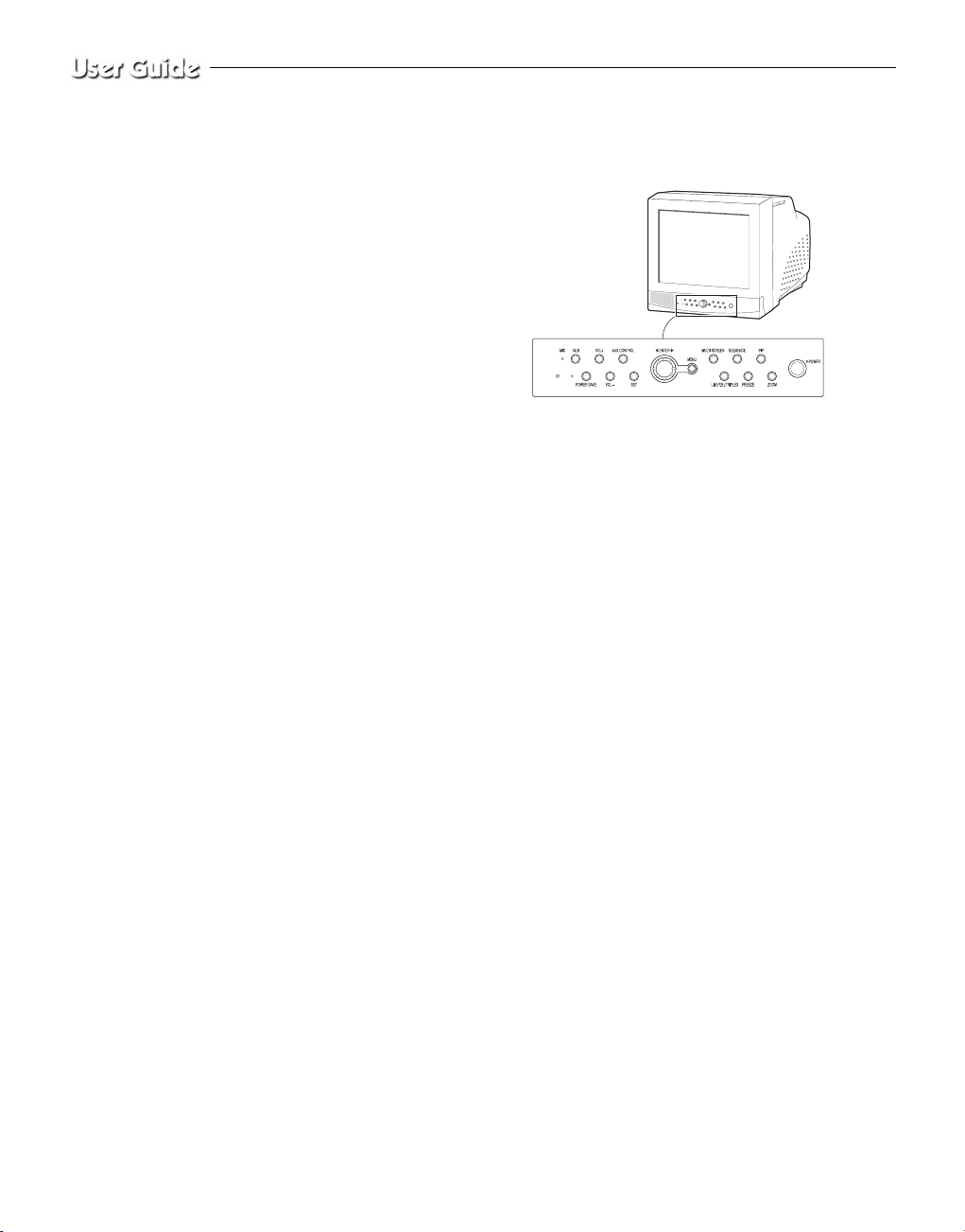
Names and Functions of Parts
Front Panel/Remote Control
A. Power Switch
Turns the power on/off.
B. POWER SAVE
Changes to Power Save mode.
C. VOLUME +/-
Controls the volume level.
D. TALK
Communicates with the doorbell in duplex mode.
E. AUX CONTROL
Outputs relay pulses to an external device for a specified time.
You can adjust this control according to your environment. (For example, when the doorbell rings, you can move to the corresponding camera and identify the visitor before opening the door using the AUX
CONTROL button.)
F. LIVE/P.B./TRIPLEX
Changes the Display mode. Each press of this button switches
between Live, P.B., and Triplex modes sequentially.
G. SET
Enters the selected Sub Menu from the Main Menu.
H. ROTARY WHEEL (LEFT, RIGHT, ENTER)
Press the LEFT button to direct the camera to the left; the RIGHT button, to the right. In the center is the ENTER button. Use this wheel to
move a Zoomed-in screen, or to scroll through Menu items or channels. Press ENTER to select an item, enter a sub menu, or replay the
events.
Eng-4
Eng-5
I. MENU
Display the Setup menu on the screen. Press it
again to exit the Setup menu.
J. MULTISCREEN
Switches to the split screen view. Each press
of this button changes to the 4, 8, and 9-split
screen sequentially. Only the 9 and 16 split
screens are available in the Triplex mode.
K. SEQUENCE
When pressed in the full screen mode, channels are switched automatically and sequentially within a specified time period.
L. FREEZE
Captures the selected screen as a still screen.
Refer to the section “When you want to
watch in FREEZE screen mode” on page
Eng-7.
M. PIP
Selects the Picture in Picture mode.
N. ZOOM
When pressed in full screen mode, the screen
is enlarged. Each press of this button enlarges
the screen two times sequentially and then
returns to the normal size. Use the Rotary
Wheel to move the Zoomed-in screen.
O. Number Key(0 ~ 9)
Press the number of the channel to watch it in full screen mode.
Or, press the SYSTEM ID button and then press the number of the
system you want to control with the remote control.
P. ZOOM(TELE/WIDE)
Only the remote control has this button. It is available only when a
camera (SOC-420(P), SOC-920(P) sold separately), is connected to
the system.
Q. FOCUS(FAR/NEAR)
Only the remote control has this button. It is used for camera Focus
control and available only when a camera (SOC-420(P), or SOC920(P), sold separately), is connected to the system.
R. IRIS(CLOSE/OPEN)
Only the remote control has this button. It is used for camera Iris control and available only when a camera (SOC-420(P), or SOC-920(P),
sold separately), is connected to the system.
S. ONEAF
Performs Auto Focus for the selected camera once in the present status. Only the remote control has this button. It is only available when
a camera (SOC-420(P), or SOC-920(P), sold separately), is connected
with the product.
T. SYSTEM ID
Selects the system to control with the remote. Only the remote control
has this button.
U. ID RESET
Located on the remote control, this button resets the selected System
ID to the default ID (1).
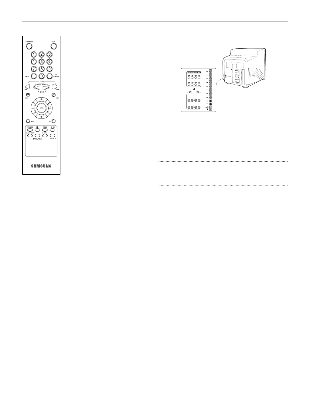
Rear Panel
A. CAMERA IN(RJ-45)
Video camera input terminals. You can connect up to 8 cameras
with RJ-45 connectors.
B. CAMERA IN (BNC)
Video camera input terminals. You can connect up to 8 cameras
with BNC connectors.
Caution
Either RJ-45 or BNC type cameras should be connected to the same
channel. Signal interference will occur if both types of camera are
connected to the same channel.
C. VCR
• Connects to the VCR using a 6-pin connector.
• TRIGGER: Trigger output terminal for the VCR
• VIDEO IN/OUT: Video input/output terminal for the VCR
• AUDIO IN/OUT: Audio input/output terminal for the VCR
D. AUX
• Connects to another device using the 4-pin connector.
• SPOT VIDEO OUT: The terminal that allows you to supervise the
specified channel within the Main screen on the additional connected
monitor.
• SPOT AUDIO OUT: The terminal that allows you listen to the sound
of the specified channel on the additional connected monitor.
• SLAVE VIDEO OUT: The terminal that allows you to view the Main
screen displayed at the present time on the additional connected
monitor.
E. ALARM
• A/O (HOT/COLD): When an alarm occurs, the Active Make signal
is output.
• A/R: Connects to the Alarm Reset terminal of VCR. When an alarm
is triggered, a pulse is output.
• G: Connects to the ground terminal of VCR.
F. ~AC IN
Connects the power cord.
Eng-6
Chapter 2: Installation
Installation Environments
This section describes the environmental requirements for safe installation and use.
Install the product on a flat table or in a rack. It should be used only
when level and should not be used when stood vertically or obliquely.
The location in which the main system is installed and the configuration
of the wiring room are very important for proper operation of the system.
When the products are installed too closely together or the location is
poorly ventilated, the system may not operate properly and maintenance
of the system may be difficult.
Sufficiently circulate the air within the system operating room and tightly
fasten the cover of the main system to prevent malfunction and reduce
system downs due to environmental causes.
There are high voltage parts inside. Do not arbitrarily open the cover.
Install the product in a place that meets the following environmental conditions. Be sure to maintain the system under the temperatures and
humidity conditions given below:
• Operating temperature : 0 °C ~ 40 °C
• Storage temperature : -20 °C ~ 60 °C
• Operating humidity : 20% ~ 85% RH
• Storage humidity : 20% ~ 95 RH
• Input voltage : AC 100 ~ 240V
• Frequency: 50/60 Hz
Caution
When operating the product, the fluctuation of input voltage must be
within 10% of the rated voltage and the external power outlet must be
grounded, otherwise, it may cause electric shock or malfunction of the
product. Do not connect heat-generating appliances such as a hair dryer,
iron or refrigerator to the same power outlet in which the product is
plugged, otherwise it may cause a fire or malfunction of the product. The
use of an Automatic Voltage Regulator (AVR) is highly recommended to
ensure that stable power is supplied.
Be sure to coil CORE-FERRITE on the connector to reduce electro-magnetic interference (EMI).
Unpacking
Remove the package cover and place the product on a flat and secure
surface or in the installation location. Check whether all the following
devices and accessories are included with the main system.
Chapter 3: Connecting to
External Devices
The product can be connected to an external device such as a monitor,
VCR, Alarm Box, Door Bell Box, etc.
This chapter describes how to connect to external devices.
Caution
Make sure not to input more than 2V from the camera, video, or audio
source, otherwise, it may cause a malfunction of the product.
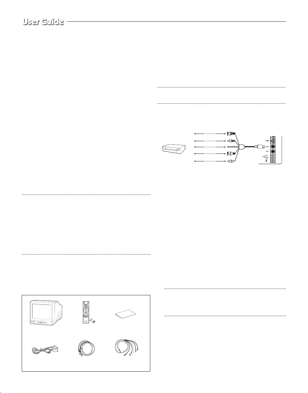
1. Connecting to Time Lapse VCR
(or Normal VCR)
1) Connect the 6-pin plug to the VCR terminal on the real panel.
2) Connect the VIDEO OUT plug to the VIDEO IN terminal of the
VCR.
3) Connect the VIDEO IN plug to the VIDEO OUT terminal of the
VCR.
4) Connect the AUDIO OUT plug to the AUDIO IN terminal of the
VCR.
5) Connect the AUDIO IN plug to the AUDIO OUT terminal of the
VCR.
6) Connect the TRIGGER plug to the REC TRIGGER OUT terminal
of the VCR.
7) Connect the A/O (HOT) terminal on the rear panel to the Alarm
IN terminal of the VCR.
8) Connect the A/O (COLD) terminal on the rear panel to the
Ground terminal of the VCR.
9) Connect the A/R terminal on the rear panel to the Alarm Reset
terminal of the VCR.
10) Connect the G (ground) terminal on the rear panel to the Ground
terminal of the VCR.
Caution
The name of the REC TRIGGER OUT or Alarm terminal may
change depending on the type of Time Lapse VCR.
Make sure to check the names of the terminals before connecting
them.
2. Connecting the Alarm Sensor
Connect the Alarm Box and Alarm Sensor in accordance with the
user manual of Alarm Box.
3. Connecting the Door Bell Box
Connect the cameras and Door Bell Box in accordance with the user
manual of Door Bell Box.
6-Pin Accessory
(VCR)
Power Cord
4-Pin
Accessory(AUX)
Remote Control/
Batteries
Color Monitor
User’s Guide
VIDEO IN
TIME LAPSE VCR
OR NORMAL VCR
VIDEO OUT
AUDIO IN
AUDIO OUT
VIDEO OUT
VIDEO IN
AUDIO OUT
AUDIO IN
TRIGGER OUT
TRIGGER
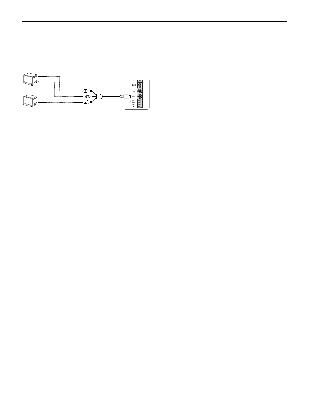
4. Connecting the Ordinary monitor
Connect the ordinary monitor to the Spot output terminal, which
allows you to supervise a specified channel within the Main screen.
Connect the Slave Monitor to the output terminal, which allows you
to simultaneously view the current situation.
Chapter 4: Basic Operation
1. Basic Operation
1) Turn the Power Switch On.
When turned on for the first time, the 9-split screens are displayed
on the monitor. At this time, the channels that have no input are
displayed with a blue screen and video loss occurs.(After completing the initial setup, the settings are memorized when the power is
turned off. Therefore, when you turn the power on again, the product will be operated with the previous settings.)
2) Select a Display Mode as follows.
• Full Screen Mode: When you are on a split screen, move to your
desired channel using the Rotary Wheel and press the ENTER
button located at its center. The selected channel will then be displayed in Full Screen Mode.
• Multi Screen Mode: Press the MULTISCREEN button to display
the split screens. You can select which channels will be displayed
on the split screen.
• Sequence Screen Mode: Press the SEQUENCE button. Channels
are automatically switched sequentially in full screen mode.
• Freeze Screen Mode: You can capture and view a still screen
using the FREEZE button and the Rotary Wheel.
• LIVE/P.B. Screen Mode: You can monitor the present camera
signals or playback the recorded screens using the
LIVE/P.B./TRIPLEX button.
• TRIPLEX Screen Mode: Watch the present camera signals and
recorded screens on the same monitor using the
LIVE/P.B./TRIPLEX button.
• PIP Screen Mode: You can watch Picture in Picture (PIP) screens
by using the PIP button.
• Zoom Screen Mode: You can enlarge a full screen two times
using the Zoom button and Rotary Wheel.
2. When you want to watch on
LIVE/P.B./TRIPLEX screen.
Select the LIVE, P.B., or TRIPLEX screen mode using the
LIVE/P.B./TRIPLEX button.
Each press of this button changes the screen mode to LIVE mode,
P.B. mode, and TRIPLEX mode sequentially.
The LIVE/P.B./TRIPLEX button will not operate in the following
cases:
• While using the SETUP Menu
• While displaying the Event List or the Door Bell List
• While replaying events
• While zooming-in the screen
• While setting a still screen on the multi screen mode
3. When you want to watch in Full Screen
Mode
If you are on a split screen, move to your desired channel using the
Rotary Wheel and press ENTER. The selected channel will be displayed in full screen mode. At this time, you can change the channel
using the Rotary Wheel.
In addition, you can change the channel by pressing number buttons
on your remote control.
4. When you want to watch in Sequence Screen
Mode
The Sequence screen is available only in full-screen LIVE mode.
Press the SEQUENCE button when the screen is in full-screen LIVE
mode to switch to the Sequence screen. You can set the switching
intervals by going to "SEQUENCE" under "4. SYSTEM SETTING"
on the SETUP MENU. The range of switching intervals is from one
to thirty seconds. Press the SEQUENCE button again to stop the
screen displayed at the present time.
The SEQUENCE button will not operate in the following cases:
• While operating in P.B. or TRIPLEX mode
• While using the SETUP Menu
• While displaying a split screen
• While displaying the Event List or Door Bell List
• While replaying events
• While zooming-in the screen
5. When you want to watch in FREEZE Screen
Mode
You can stop a full or split screen temporarily and view the still
screen in LIVE, P.B., TRIPLEX mode.
You can select and stop the channels you wish to stop in split screen
mode.
1) Full Screen Display
If the FREEZE button is pressed, the current display will freeze,
and the FREEZE icon will appear in the upper right corner of the
screen. Press the FREEZE button again to exit this mode.
2) Multi-Screen Display
! If the FREEZE button is pressed, the FREEZE icon will
appear in the upper right corner of the screen.
@ Move to the picture you would like to freeze by using Rotary
Wheel.
# By pressing the ENTER button in the middle of Rotary
Wheel, the picture from that channel will freeze, and the
character “F” will appear. Press the ENTER button again to
exit this mode.
$ If you would like to see the frozen picture from another chan-
nel, move to the target channel, and press ENTER.
Eng-7
VIDEO IN
AUDIO
IN
SPOT VIDEO OUT
SPOT AUDIO OUT
SLAVE VIDEO OUT
VIDEO IN

Eng-8
The new channel’s picture will be frozen, and the character
“F” will appear. Press the ENTER button again to exit this
mode.
% If the picture on any other channel remains frozen, repeat
item $)
^ Press the FREEZE button to exit entirely from FREEZE
mode.
The FREEZE button will not operate in the following cases:
• While using the SETUP Menu
• While displaying the Event List or Door Bell List
• While replaying events
6. When you want to watch on ZOOM Screen
Mode
This mode is operated only while in LIVE/P.B. Mode Full Screen.
1) When the ZOOM button is pressed, a ZOOM AREAwill appear
in the center of the screen.
2) Move the ZOOM AREA to the target position by using the Rotary
Wheel and the ENTER button.
3) Press the ZOOM button again to increase picture to double its
original size.
4) Press it again to return to the original size.
ZOOM AREA and ZOOM Picture Movement
1) Press the ZOOM button and turn the Rotary Wheel to move the
ZOOM AREA up and down over the picture.
2) Press the ENTER button and turn the Rotary Wheel to move the
ZOOM AREA left and right over the picture.
3) Press the ENTER button again and turn the Rotary Wheel to
move the ZOOM AREA up and down over the picture.
The ZOOM button will not operate in the following case:
• While using the SETUP Menu
• While Displaying he EVENT List or Door Bell List
• While Replaying events
• While operating in Sequence Mode
7. When you want to watch on PIP Screen
Mode
You can watch a Picture in Picture screen in full-screen LIVE mode
using the PIP button.
When you press the PIP button for the first time, the sub screen on
the PIP screen is a sequence screen. After that, when you enter into
PIP mode again, the sub screen which is displayed in the same screen
mode as when you exited the PIP mode previously.
Using PIP Screen
1) Press the PIP button in full-screen LIVE mode.
2) When a fixed channel is displayed on the sub screen, each time
you press ENTER it switches between the Main screen and the
Sub screen.
3) Turn the Rotary Wheel to change the channel of the Main screen.
4) Press the SEQUENCE button to set the Sub screen as the
sequence screen. Press the button again to fix the channel.
5) You can change the position of the sub screen by going to “PIP
POSITION” under “2.CLOCK/DISPLAY SET” on the SETUP
menu.
The PIP button will not operate in the following cases:
• While operating in P.B. or TRIPLEX mode
• While displaying a split screen
• While using the SETUP Menu
• While displaying the Event List or Door Bell List
• While replaying events
• While zooming-in the screen
• While operating in Sequence mode
• In case of no Video input signal
• When the input signal channel is in the Full-screen mode at the
time of Single video input
8. When you want to watch the VCR output
Change to PB FULL Mode by pressing the Live/P.B./TRIPLEX
button. The “PB THROUGH” picture will appear if the ENTER
button is pressed while in this mode. Press the”ENTER” button
again to return to the previous PB picture.
Caution
This function is only available in PB FULL Display mode.
9. When you want to watch the Event Replay
screen
1) When an Alarm/Motion signal is input
You can use the alarm function only when an Alarm Box is connected. When an alarm/motion signal is input, the word "EVENT"
is displayed on the screen, and a warning buzzer sounds. When
this occurs, if you press ENTER, up to 16 frames before and after
the generated alarm/motion signal are replayed on the Event
Replay window.
Press ENTER again to stop the event replay.
If alarm/motion signals are input on more than one channel, press
ENTER to start the event replay for another channel when the
current event replay finishes. When an event replay for all the
channels on which an alarm/motion signal has occurred has finished, press ENTER to exit Event Replay mode.
Alarm/Motion histories are recorded in the EVENT LIST.
2) When Channel Loss is detected
If the channel loss detection function detects a channel loss, the
word "EVENT" is displayed on the screen and a warning buzzer
sounds. When this occurs, press ENTER and up to 16 frames
before the detected channel loss are replayed on the Event Replay
window.
Press ENTER again to stop the event replay. If channel loss is
detected on more than one channel, press ENTER to start event
replay for the next channel when the current event replay finishes.
When the event replay for all the channels on which channel loss has
been detected finishes, press ENTER to exit the Event Replay mode.
Channel loss histories are recorded in the EVENT LIST.
10. When you want to watch a Door Bell
screen
The Door Bell Function is only available with a door bell connection. When the door bell is pressed, the current picture switches to
the doorbell area monitoring picture, in full screen mode, along
with an alarming beep. At this time, one Instant Picture is stored in
the "DOOR BELL LIST". Up to 8 pictures can be stored in the
"DOOR BELL LIST".
You can access any stored picture from the list to be displayed on
the screen.
Move to your desired item by going to "5. DOOR BELL LIST" on
the SETUP menu and press ENTER to display it as a still screen.
Then, press ENTER again to return to the "DOOR BELL LIST"
screen.
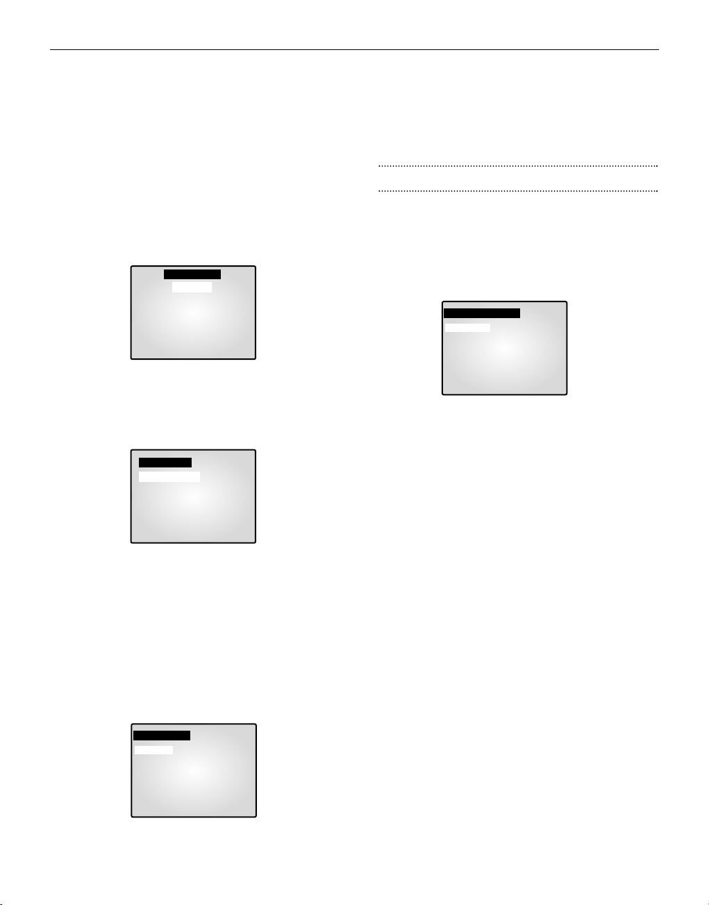
Chapter 5: Setup Menu Settings
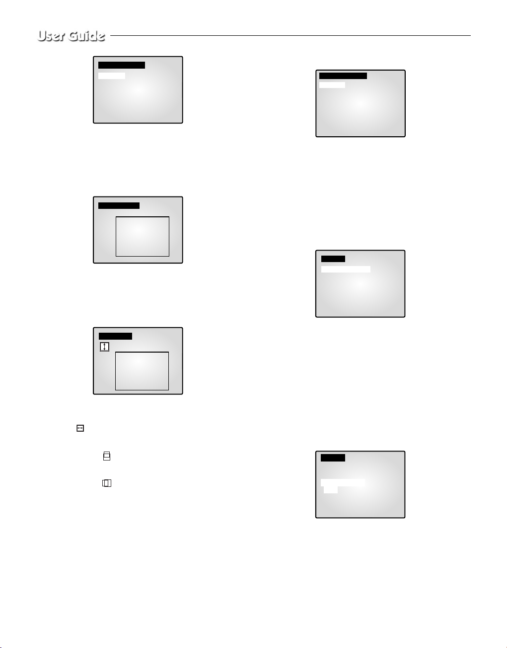
<SETUP MENU>
• Press the MENU button to display the Language Selection
screen.
• Select the desired language by using the Rotary Wheel and press
ENTER to display the SETUP MENU in the desired language.
• When you press the MENU button after completing the initial
language selection, the Language Select screen will not appear.
Instead the following SETUP MENU will appear on the monitor.
Press the button once again to return to the previous menu.
<SUB MENU >
• Select submenu 1 to 6 from the SETUP MENU using the Rotary
Wheel and press ENTER to go to the SUB MENU.
1. VIEW SETTING
You can change the contrast, brightness, color, sharpness and tint
of the Main screen on the monitor. Select “1. VIEW SETTING”
from the SETUP MENU using the Rotary Wheel and press
ENTER to display the following screen:
• Select an item using the Rotary Wheel and press ENTER to
change the preset value.
• Change the preset value (0 ~ 100) by using the Rotary Wheel
and press ENTER to save the setting.
• Select SAVE (save the changes), QUIT (exit the setting mode
without saving) or PRESET (reset all the settings to the factory
defaults) from the EXIT MENU and press ENTER to return to
the SETUP MENU.
Caution
The “TINT” item is only available in NTSC SYSTEM mode.
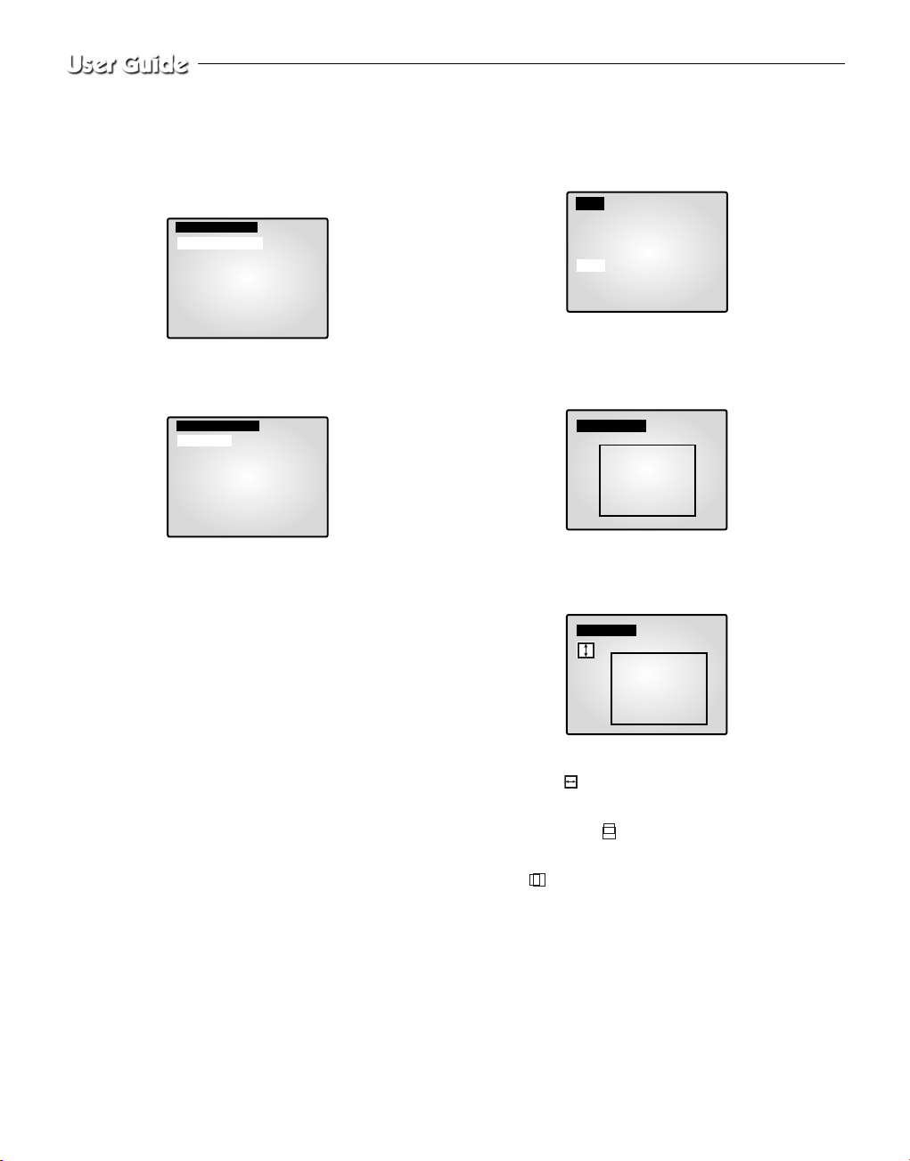
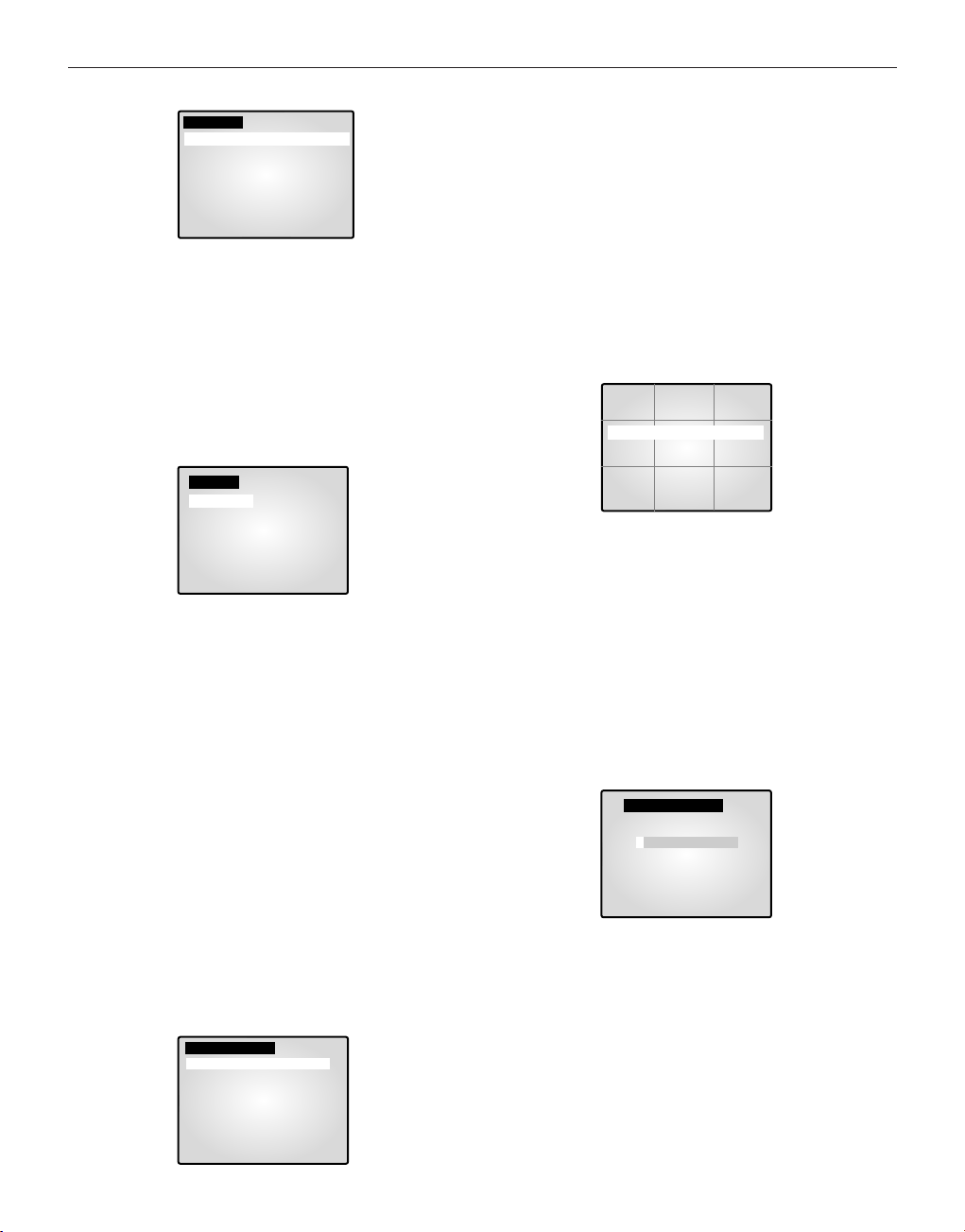
2. CLOCK/DISPLAY SET
You can change PIP position, display type, date type and time.
Select “2. CLOCK/DISPLAY SET” from the SETUP MENU using
the Rotary Wheel and press ENTER to display the following screen:
• Select an item using the Rotary Wheel and press ENTER to
change the preset value.
• Change the preset value using the Rotary Wheel and press ENTER
to save the setting.
• Press the MENU button to return to the SETUP MENU.
PIP POSITION: BOTTOM-RIGHT ↔ TOP-LEFT ↔ TOP-
RIGHT ↔ BOTTOM-LEFT.
• Select the PIP position among the four options listed above.
DISPLAY TYPE: ALL ↔ TITLE ↔ DATE/TIME ↔ NONE.
• ALL: All items will be displayed except the DATE/TIME and the
TITLE.
• TITLE: Only the CHANNEL TITLE will be displayed.
• DATE/TIME: Only the DATE/TIME will be displayed.
• NONE: Neither the DATE/TIME nor the TITLE will be displayed.
BORDER COLOR: GRAY ↔ BLACK
• GRAY : BORDER LINE COLOR is displayed in GRAY in
Multi Screen mode.
• BLACK : BORDER LINE COLOR is displayed in BLACK in
Multi Screen mode.
DATE TYPE: YY/MM/DD ↔ MM/DD/YY ↔ DD/MM/YY.
DATE [YY/MM/DD]
• Year(YY) : 00(2000) ~ 99(2099)
• Month(MM) : 01 ~ 12
• Day(DD) : 01 ~ 31
TIME [HH:MM:SS]
• Hour(HH) : 00 ~ 23
• Minute(MM) : 00 ~ 59
• Second(SS) : 00 ~ 59
Eng-9
[SETUP MENU]
1. VIEW SETTING
2. CLOCK/DISPLAY SET
3. CAMERA SETUP
4. SYSTEM SETTING
5. EVENT LIST
6. DOOR BELL LIST
[LANGUAGE]
ENGLISH
ESPAÑOL
FRANÇAIS
ITALIANO
DEUTSCH
NEDERLANDS
PORTUGUÊS
[VIEW SETTING]
CONTRAST 50
BRIGHT 50
COLOR 50
SHARPNESS 50
TINT 50
EXIT QUIT
[CLOCK/DISPLAY SET]
PIP POSITION BOTTOM RIGHT
DISPLAY TYPE ALL
BORDER COLOR GRAY
DATE TYPE YY/MM/DD
DATE[YY/MM/DD] 04/01/01
TIME [HH:MM:SS] 12:30:01
Eng-10
3. CAMERA SETUP
You can change the Camera ID, LOSS DETECT, MOTION
DETECT and Camera Preset values.
Select “3. CAMERA SETUP ”from the MAIN MENU using the
Rotary Wheel and press ENTER to display the following screen.
Select the desired channel using the Rotary Wheel and press ENTER
to go to the display of the selected channel. The following screen
will appear.
• All the items, except “CAMERA ID ”and “LOSS DETECT,” will
be available for setting only after the system is connected to a
camera (SOC-420(P) or SOC-920(P), sold separately).
• Select the desired item using the Rotary Wheel and press ENTER.
Then change the preset value using the Rotary Wheel and press
ENTER to complete the setting.
• Select SAVE (save the changes), QUIT (exit the setting mode
without saving) or PRESET (reset all the settings to the factory
defaults) from the EXIT menu and press ENTER to return to the
previous CAMERA SETUP menu.
You can’t return to the previous menu while in the setting mode.
You can only return to the previous menu by selecting EXIT.
• Change the preset values for the other channels repeating the same
steps.
• Press the MENU button after completing all the settings to return
to the SETUP MENU.
CAMERA ID:
---CH1----(“-” indicates blank.)
• Select “CAMERA ID” using the Rotary Wheel and press ENTER to
select the first “- .”
• Select the desired letter using the Rotary Wheel and press ENTER to
move on and select the next letter.
(Letter order: 0123456789ABCDEFGHIJKLMNOPQRSTUVWXYZ[
]~_ . / )
• Repeat the same to select all the desired letters. (You can choose up to
ten letters.)
LOSS DETECT:
Sets the Loss Detect On/Off. (ON ↔ OFF)
IRIS:
Controls the video output level through the Iris depending on the
level of light coming into the camera.
• Select “IRIS” using the Rotary Wheel and press ENTER to select
either “ALC...” or “MANUAL…”.
• ALC... : Auto Light Compensation
- Select “ALC...” using the Rotary Wheel and press the SET button to
display the following screen. Press the MENU button after completing the setting to return to the previous menu.
- Select AREA using the Rotary Wheel and press ENTER to select
either “PRESET...” or “USER…”.
- Select “PRESET...” using the Rotary Wheel and press the SET button to display the following screen. The back light compensation will
be applied to the area(s) with preset values.
Press the MENU button to return to the previous menu.
- Select “USER…” using Rotary Wheel and press the SET button to
display the following screen.
❙ Adjust the size up/downward using the Rotary Wheel and press
ENTER to select and move on to adjust the size on the left/right
side. Then “ ” will be displayed on the screen.
❙ Press ENTER after adjusting the size of the left/right side by using
the Rotary Wheel. Then you will be ready to adjust the position
up/downward and “ ” will be displayed on the screen.
❙ Press ENTER after adjusting the position using the Rotary Wheel.
Then you will be ready to adjust the position to the left/right side
and “ ” will be displayed on the screen.
❙ Press ENTER after adjusting the position using the Rotary Wheel.
Then you have completed the AREA setting. Press the MENU button to return to the previous menu.
- BLC (Back Light Compensation): When BLC is turned “ON,”BLC
function will be applied to all the areas set in AREA. When bright light
is in the background of an object, the object will appear dark on the
monitor due to the backlight. To address this problem, use the BLC
function so that you can get clear images.
- LEVEL: You may set the video output level from “-9” to “+9”.
Select “LEVEL [00]” using the Rotary Wheel and press ENTER to
change the setting. Press ENTER after changing the setting to save the
setting.
[SETUP CAMERA 1]
CAMERA ID ---CH1---LOSS DETECT ON
IRIS ALC...
SHUTTER OFF
WHITE BALANCE ATW
SPECIAL...
FOCUS ONEAF
MOTION DETECT...
EXIT SAVE
[ALC]
AREA PRESET...
BLC OFF
LEVEL[ 00 ] ----------+----------
[PRESET AREA]
[CAMERA SETUP]
SETUP CAMERA 1...
SETUP CAMERA 2...
SETUP CAMERA 3...
SETUP CAMERA 4...
SETUP CAMERA 5...
SETUP CAMERA 6...
SETUP CAMERA 7...
SETUP CAMERA 8...
[USER AREA]
• MANUAL...: Sets the manual opening/closing of the Iris.
- Select “MANUAL...” using the Rotary Wheel and press SET button to
display the following screen.
- Set the value using the Rotary Wheel.
- Press the MENU button to return to the previous menu.
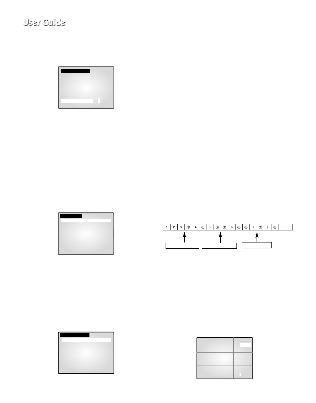
SHUTTER
- You can set the high-speed electronic shutter speed, AUTO low-speed
shutter speed and FIX low-speed shutter speed.
- High-speed electronic shutter can be set to 7 shutter speeds ranging
from 1/120(1/100) sec to 1/10K sec. Auto low-speed shutter and FIX
low-speed shutter can both be set to 12 shutter speeds ranging from
X2 to X128.
- Low-speed slows down the speed of the shutter so that images taken
in dark light appear clearer on the screen. Select AUTO low-speed
shutter to detect the density of light and automatically slow down the
speed of the shutter depending on the density. Select FIX low-speed
shutter to set the speed of the shutter manually.
- The numbers following the AUTO and FIX items indicate the num-
ber of fields stored. The higher the number is, the lower the speed of
the shutter becomes. Images, therefore, appear most clear with still
pictures. With moving images, however, the object can appear
blurred.
- Setting the Value
From the SHUTTER Menu press ENTER to adjust the values. Select
the value using the Rotary Wheel and press ENTER to complete the
setting.
OFF ’ 1/120(1/100) ’1/250 ’ 1/500 ’ 1/1000 ’1/2000 ’ 1/4000 ’
1/10K ’ OFF ’AUTO X2 ’ AUTO X4 ’ AUTO X6 ’AUTO X8 ’
AUTO X12 ’AUTO X16 ’AUTO X24 ’AUTO X32 ’ AUTO X48 ’
AUTO X64 ’AUTO X96 ’AUTO X128 ’OFF ’ FIX X2 ’ FIX X4 ’
FIX X6 ’ FIX X8 ’FIX X12 ’ FIX X16 ’ FIX X24 ’FIX X32 ’ FIX
X48 ’ FIX X64 ’FIX X96 ’ FIX X128.
WHITE BALANCE:
AT W, AWC.., MANUAL...
• You can turn on the White Balance function that enables the color
white to appear normal regardless of the color temperature of light.
• ATW : Monitors the change in color temperature and adjusts the setting of the White Balance accordingly.
• AWC : Adjusts the setting of the White Balance to the color temperature only once and then maintains the setting. While in the AWC
screen, place a white paper in front of the camera and press the SET
button.
• MANUAL... : Select “MANUAL” using the Rotary Wheel and press
the SET button to display the following screen. Then you can choose
3200K, 5600K or USER Mode and set the White Balance manually
depending on the current lighing conditions.
- 3200K : Sets the color temperature at 3200° K.
- 5600K : Sets the color temperature at 5600° K.
- Set to “OFF[USER]” to display the following screen. Press ENTER
and then select the proper values of RED and BLUE to manually set
the color temperature.
Press the MENU button to return to the previous menu.
SPECIAL...
• Select “SPECIAL..” using the Rotary Wheel and press ENTER to display the following screen. Press the MENU button after completing the
setting to return to the previous menu.
• AGC : AGC(Auto Gain Control) function On/Off.
• MIRROR : Horizontally reverses the video output signals.
• D-ZOOM : Sets the magnifying rate of the Digital Zoom. This system offers up to 10X Zoom.
• POSI/NEGA : Sets the video output signals to either normal or
reverse output.
• ZOOM SPEED : Sets the moving speed of the Zoom.
- 1: Takes about 17 sec from x1 to x12 (the lowest speed)
- 2: Takes about 10 sec from x1 to x12 (low speed)
- 3: Takes about 6 sec from x1 to x12 (high speed)
- 4: Takes about 3 sec from x1 to x12 (the highest speed)
• DETAIL : Adjusts brightness vertically and horizontally.
FOCUS: Set the Focus to MF or ONEAF.
• MF: Manual Focus Mode allows the user to Focus.
• ONEAF: When the Zoom moves from the Wide to the Telephoto
direction, AF occurs only once after the Telephoto function is completed.
- ONEAF works like MF Mode when there are still images and
like AF Mode when the Zoom moves in the Telephoto direction.
MOTION DETECT...
• The Motion Detect feature is used to detect motion of an object. By
turning on the Motion Detect, you can detect the motion of an intruder
during non-peak hours.
• Select “MOTION DETECT” using the Rotary Wheel and press ENTER to
display the following screen. Press the MENU button after completing the
setting to return to the previous menu.
[MANUAL]
LEVEL[ 00 ] -------------+-------------
[MANUAL]
PRESET 3200K
[MANUAL]
PRESET OFF [USER]
RED [ 00 ] --------+-------BLUE[ 00 ] --------+--------
[SPECIAL]
AGC ON
MIRROR OFF
D-ZOOM OFF
POSI/NEGA +
ZOOM SPEED 3
DETAIL [ 0 ] -------+-------
Eng-11
• AREA SET : Sets the area of the screen to which the Motion Detector
is applied.
- PRESET...
❙ Select “PRESET” using the Rotary Wheel and press the SET but-
ton to display the following screen. The Motion Detect is applied
to the area(s) within the box.
Press the MENU button to return to the previous menu.
- USER...
❙ Select “USER... “ using the Rotary Wheel and press the SET but-
ton to display the following screen.
❙ Adjust the size up/downward using the Rotary Wheel and press
ENTER to select and move on to adjust the size of left/right side.
Then “ ” will appear on the screen.
❙ Adjust the size of the left/right side by using the Rotary Wheel and
press ENTER to select and move on to adjust the position
up/downward. “ ” will appear on the screen.
❙ Adjust the position up/downward using the Rotary Wheel and press
ENTER to select and move on to adjust the position of the
left/right side. “ ” will appear on the screen.
❙ Adjust the position of the left/right side using the Rotary Wheel
and press ENTER. Then you will have completed the AREA setting. Press the MENU button to return to the previous menu.
• SENSITIVITY: Sets the sensitivity of the Motion Detector to LOW,
MEDIUM or HIGH.
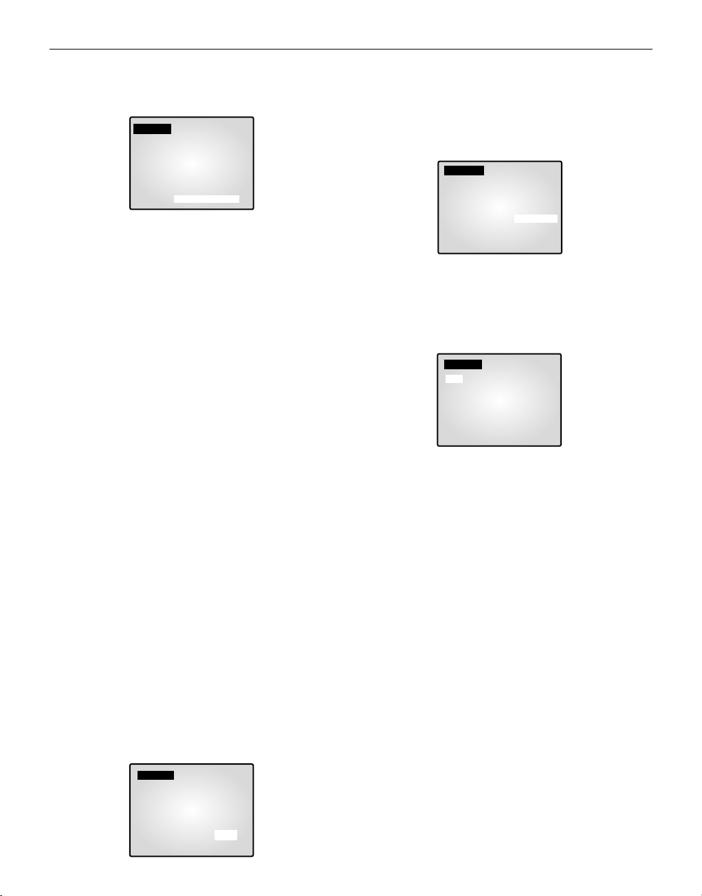
4. SYSTEM SETTING
You can change the ALARM, RECORD, HIDDEN CAMERA,
SEQUENCE, SYSTEM ID, PASSWORD, and LANGUAGE settings.
Select “4. SYSTEM SETTING” from the SETUP MENU using the
Rotary Wheel and press ENTER to display the following screen.
- Select an item using the Rotary Wheel and press ENTER to change
the setting.
- Change the setting using the Rotary Wheel and press ENTER to
save the setting.
- Press the MENU button after completing all the settings to return
to the SETUP MENU.
ALARM...
• Select “ALARM” using the Rotary Wheel and press ENTER to display
the following screen.
ALARM HOLD TIME
ALARM HOLD TIME is the time during which the Alarm continues.
Yo u can set the duration at 5 sec, 15 sec, 30 sec, 1 min, 3 min, 5 min, 10
min, 20 min, 30 min or AUTO. When you select AUTO, the Alarm will
be on during the time the Alarm is signaling.
ALARM BUZZER
When the Alarm occurs, the Alarm Buzzer is set off. You can set the
duration at 5 sec, 15 sec, 30 sec, 1 min or OFF. When you select OFF,
the Alarm Buzzer will not sound.
• Select “ALARM PATTERN” using the Rotary Wheel and press
ENTER to display the following screen.
• You can select when to arm and disarm the alarm in two patterns.
When you select PATTERN A, The time in PATTERN B will be automatically modified.
• Select PATTERN A using the Rotary Wheel and press ENTER to display the following screen.
Eng-12
[MOTION DETECT]
AREA SET PRESET...
SENSITIVITY MEDIUM
[PRESET AREA]
[USER AREA]
[SYSTEM SETTING]
ALARM...
RECORD...
HIDDEN CAMERA...
SEQUENCE 02 [ SEC]
SYSTEM ID 1..
PASSWORD CHECK OFF
PASSWORD CHANGE..
LANGUAGE ENGLISH..
[ALARM]
ALARM HOLD TIME 01 [MIN]
ALARM BUZZER 05 [SEC]
ALARM PATTERN..
[ALARM]
ALARM HOLD TIME 01 [MIN]
ALARM BUZZER 05 [SEC]
ALARM PATTERN..
TIME 08:00 - 17:00 [PATTERN A]
17:00 - 08:00 [PATTERN B]
PATTERN A...
PATTERN B...
• Choose On/Off for the Motion, Alarm and Door-Bell features for all 8
cameras.
• Press the MENU button after completing the settings to return to the
ALARM Menu.
• Repeat the same for PATTERN B.
• The “--” will be displayed when it is not connected to the accessories.
RECORD...
• Select “RECORD…” using the Rotary Wheel and press ENTER to display the following screen.
REC TYPE
• NOR : Used for recording with a normal VCR. The picture is displayed according to the “REC OUT” set values (FIELD, FRAME).
• TLV: Used for recording through a time lapse VCR.
REC OUT
It is valid when the REC TYPE is “NOR”.
• FIELD : Records at 1/50 seconds (PAL), 1/60 seconds (NTSC).
• FRAME : Records at 1/25 seconds (PAL), 1/30 seconds (NTSC).
AUDIO RECORD
Sets the channel that sends Audio signals to the recoding output.
SPOT-OUTPUT
Sets the output channel for SPOT which will intensely monitor that
channel.
• Press the MENU button after completing the settings to return to the
SYSTEM SETTING Menu.
HIDDEN CAMERA
• Select “HIDDEN CAMERA…” using the Rotary Wheel and press
ENTER to display the following screen.
• Turn the Hidden Camera On/OFF of in LIVE Mode and P.B. MODE
for each channel.
• Press the MENU button after completing the settings to return to the
SYSTEM SETTING Menu.
SEQUENCE
• Set the Switching Interval for Sequence Mode. You can set the time
between 1 sec and 30 sec.
SYSTEM ID
• This function allows the user to control a single monitor using the
remote control when multiple (up to 10) monitors are linked together.
Only those monitors with IDs matching the Remote Control ID will be
controlled by the remote control.
• Setting: The default value of the monitor and the remote control is “1”.
The value of the Monitor ID can be set from 0 to 9 by accessing the
System ID Setup mode under the System Setting menu. Press the
System ID button on the remote control to display the Monitor ID and
the Remote Control ID as shown above. With system ID button
pressed, enter the desired number by pressing the corresponding button
(0 to 9) to set up the Remote Control ID. The OSD will disappear three
seconds after the last button is pressed.
PASSWORD CHECK
• Turns the Password Check On/OFF for entry into the SETUP MENU.
• When PASSWORD CHECK is “ON” for entry into the SETUP
MENU, the following screen will appear and the first space for a number will be selected.
• Select the first digit of the Password using the Rotary Wheel and press
ENTER to move to the next digit. Repeat this step to enter the six-digit
password and press ENTER to return to the SETUP MENU.
• If the Password is not correct, “ERROR TRYAGAIN” will appear at
the bottom of the screen. The message will disappear after the first
digit of the Password is entered. Repeat this step until you have entered
the six-digit password then press ENTER to move to the SETUP
MENU. If the number is entered incorrectly more than three times, the
display will return to the previous menu.
[PATTERN A]
CH MOTION ALARM DOOR-BELL
CH1 OFF -- OFF
CH2 OFF -- -CH3 -- OFF OFF
CH4 OFF OFF OFF
CH5 OFF OFF OFF
CH6 OFF OFF OFF
CH7 OFF OFF OFF
CH8 OFF OFF OFF
[RECORD]
REC TYPE NOR
REC OUT FRAME
AUDIO RECORD CH1
SPOT - OUTPUT CH1
[HIDDEN CAMERA]
CH LIVE P.B.
CH1 OFF OFF
CH2 OFF OFF
CH3 ON OFF
CH4 OFF OFF
CH5 OFF OFF
CH6 OFF OFF
CH7 OFF OFF
CH8 OFF OFF
CH1 CH2 CH3
CH4 CH5 CH6
CH7 CH8
MONITOR ID:1 REMOCON ID: 1
[PASSWORD CHECK]
++++++++++++++++++++++
+ - - - - - - +
++++++++++++++++++++++
Eng-13
PASSWORD CHANGE...
• Select “PASSWORD CHANGE...” using the Rotary Wheel and press
ENTER to display the current Password on the screen as shown
below. The first digit of the number will be selected. (Factory default is
123456.)
• Select the first digit of the Password using the Rotary Wheel and press
ENTER to select the second digit. Repeat the same until the six digits
of the Password have been entered. Press ENTER to complete the
change.
- You can use “0” to “9” for the Password.
LANGUAGE
• Select the desired language for the use in the Menu. ENGLISH,
ESPAÑOL, FRANÇAIS, ITALIANO, DEUTSCH, NEDERLANDS
and PORTUGUÊS are available.
5. EVENT LIST
You can check the ALARM/MOTION/LOSS EVENT LIST.
Select “5. EVENT LIST“ from the SETUP MENU using the Rotary
Wheel and press ENTER to display the following screen.
• The latest information on Alarms, Loss and Motion Detects will be
stored. This system stores up to 50 events (10 x 5 pages) staring
from the latest one. You can check the other pages of the List by
using the Rotary Wheel.
• Press the MENU button to return to the SETUP MENU.
6. DOOR BELL LIST
To check the EVENT LIST of the DOOR BELL(S).
Select “6. DOOR BELL LIST” from the SETUP MENU using the
Rotary Wheel and press ENTER to display the following screen.
• The latest information from the Door Bell detector will be stored.
This system stores up to 8 events starting from the latest one. Scroll
down the List using the Rotary Wheel and press ENTER to display
the still screen of the corresponding Door Bell. Press ENTER to
return to the DOOR BELL LIST.
• Press the MENU button to return to the SETUP MENU.
Chapter 6: Recording
1. Recording in Time Lapse (or Normal) Mode
• Image signals transmitted from up to 8 cameras play at 1/25 or 1/50
second intervals in PAL SYSTEM areas, and at 1/30 or 1/60 second
intervals in NTSC SYSTEM areas, and are recorded in the VCR.
• The TRIGGER OUT port of the VCR must be connected to the
TRIGGER (6PIN VCR Accessory) port of this system.
• When trigger signals from the VCR stop for more than 30 sec, the
Self Trigger mode is turned on to continue recording without the
trigger from the VCR.
2. Alarm/Motion Channel Intensive-Recording
• This system double-records channels in case of an Alarm/Motion.
• It records the Alarm/Motion channels in between recording the output channels.
• The “VIDEO LOSS” channel is also subject to the Alarm/Motion
Channel Double-Recording.
• Ex.) The ALARM is turned on at CH2.
Then MOTION occurs at CH5.
Chapter 7: Alarm, Motion, Loss
and Door Bell
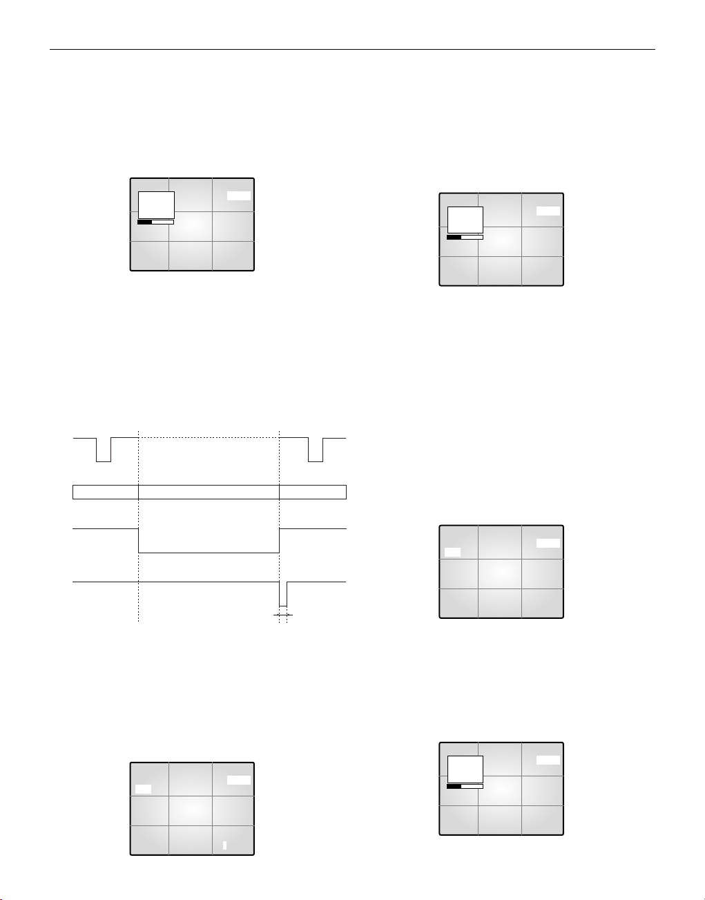
1. Alarm Occurrence
The Alarm becomes available only when an Alarm Box is connected.
1) When an Alarm trigger is received, a warning buzzer sounds and
the screen is divided into 9 Live-Mode sub-screens. The word
“EVENT” appears on the screen and the Alarm occurrence information is displayed at the right bottom of the screen.
[SYSTEM SETTING]
ALARM...
RECORD...
HIDDEN CAMERA..
SEQUENCE 02 [SEC]
SYSTEM ID 1..
PASSWORD CHECK OFF
PASSWORD CHANGE.. 123456
LANGUAGE ENGLISH..
[ EVENT LIST] 1/5
YY/MM/DD HH:MM:SS CH
1 . 04/01/30 12:30:01 M 01
2 . 04/01/29 12:30:01 A 02
3 . 04/01/28 12:30:01 M 08
4 . 04/01/27 12:30:01 A 04
5 . 04/01/26 12:30:01 A 03
6 . 04/01/25 12:30:01 L 01
7 . 04/01/24 12:30:01 A 06
8 . 04/01/23 12:30:01 M 07
9 . 04/01/22 12:30:01 A 01
10. 04/01/21 12:30:01 A 01
[ DOOR BELL LIST]
YY/MM/DD HH:MM:SS CH
1 . 04/01/30 12:30:01 D 01
2 . 04/01/29 12:30:01 D 02
3 . 04/01/28 12:30:01 D 08
4 . 04/01/27 12:30:01 D 04
5 . 04/01/26 12:30:01 D 03
6 . 04/01/25 12:30:01 D 01
7 . 04/01/24 12:30:01 D 06
8 . 04/01/23 12:30:01 D 07
CH2: Alarm Occurs
CH5: Motion Occurs
CH2: Alarm Off
04/01/01 12:30:30
EVENT
CH1 CH2 CH3
CH4 CH5 CH6
CH7 CH8 A12345678
Eng-14
2) Press ENTER (in the middle of the Rotary Wheel) to replay the event
in Event Replay mode. Up to 16 screens can be replayed centering on
the time of the Alarm. The duration of Replay is displayed in a graph.
Turn the Rotary Wheel during the Replay to forward or reverse the
stored screens one by one.
Press ENTER to terminate the Event Replay. The Event Replay will
continue until ENTER has been pressed.
3) Alarm occurrence information is stored in the “EVENT LIST”.
4) Alarm Out (HOT, COLD) signals are active during the “ALARM
HOLD TIME. ”
• ALARM HOLD TIME : Time during which the Alarm function
is carried on after the Alarm is first detected. Alarm Hold Time
is reset automatically when Event Replay is turned on.
5) Recording output continues in Normal mode until the Alarm is
cleared. The recording frequency of the corresponding channel
increases.
6) Signals change as the Alarm occurs and later clears.
2. Motion Occurrence
The Motion option only becomes available when a camera with
Motion features is connected.
1) When a Motion trigger is received, a warning buzzer sounds and
the screen is divided into 9 Live-Mode sub-screens. The word
“EVENT ”appears on the screen and the Motion occurrence information is displayed at the bottom right of the screen.
2) Press ENTER (in the middle of the Rotary Wheel) to replay the event
in Event Replay mode. Up to 16 screens can be replayed centering on
the time of the Motion occurrence.
The duration of the replay is displayed in a graph.
Turn the Rotary Wheel during the Replay to forward or reverse the
stored screens one by one.
Press ENTER to terminate the Event Replay. The Event Replay will
continue until ENTER has been pressed.
3) Motion occurrence information is stored in the “EVENT LIST”.
4) Alarm Out (HOT, COLD) signals are active during “ALARM
HOLD TIME”.
5) Recording output continues in Normal mode until the Motion is
cleared. The recording frequency of the corresponding channel
increases.
6) Signal output continues as the Motion occurs and later clears.
3. Loss Occurrence
1) When the Loss occurs, a warning buzzer sounds and the screen is
divided into 9 Live-Mode sub-screens. The word “EVENT” and
Loss channel appears on the screen and the corresponding channel
appears Blue Black.
When more than one Loss occurs, that channel number display
switches to Blue-Black with a 1 second interval.
2) Press ENTER (in the middle of the Rotary Wheel) to replay the event
in the Event Replay mode. Up to 16 screens can be replayed centering
on the time before the Loss occurrence. The duration of the Replay is
displayed in a graph.
Turn the Rotary Wheel during the Replay to forward or reverse the
stored screens one by one.
Press ENTER to terminate the Event Replay. The Event Replay will
continue until ENTER has been pressed.
04/01/01 12:30:30
EVENT
CH2 CH3
CH4 CH5 CH6
CH7 CH8
1
ALARM
04/01/01
12:29:30
150ms or Above
VCR Trigger
Trigger ignored
Recording
Output
Time Lapse Mode
Normal Mode Time Lapse Mode
Alarm Output
Alarm Reset Output
Alarm/Motion Occurrence
Alarm Reset
04/01/01 12:30:30
EVENT
CH2 CH3
CH4 CH5 CH6
CH7 CH8
1
MOTION
04/01/01
12:29:30
04/01/01 12:30:30
EVENT
CH1 CH2 CH3
CH4 CH5 CH6
CH7 CH8 M12345678
04/01/01 12:30:30 L12345678
EVENT
CH1 CH2 CH3
CH4 CH5 CH6
CH7 CH8
04/01/01 12:30:30 L12345678
EVENT
CH2 CH3
CH4 CH5 CH6
CH7 CH8
1
LOSS
04/01/01
12:30:00
Eng-15
3) Loss occurrence information is stored in the ”EVENT LIST”.
4) When the corresponding camera is reconnected, the old settings
are canceled and the factory default settings are reinstated.
4. Door Bell Occurrence
The Door Bell option is only available when a Door Bell Box is connected.
1) When a door bell is pressed, the current picture switches to the
doorbell area monitoring picture, in full screen mode, along with
an alarming beep.
2) When the Door Bell is pressed, a still screen is stored in the
“DOOR BELL LIST”.
3) Up to 8 still images can be stored in the “DOOR BELL LIST” and
the selected List can be displayed on the screen.
4) Select the desired list from “6. DOOR BELL LIST ” in the
SETUP MENU and press ENTER in to replay the still screen of
the corresponding Door Bell.
Press ENTER again to return to the “DOOR BELL LIST”.
Appendix
Specifications
1. Model Name
- SMO-210TRN(P)
- SMO-150TRN(P)
2. Video Input
- CAMERA 8 Input : 1.0Vp-p, 75Ω (vertical),
RJ-45 Type, CVBS
- VCR 1 Input (to Video Out of VCR) : 1.0Vp-p, 75Ω (vertical),
S-Jack Type, CVBS
3. Video Output
- Monitor 2 Output
SPOT : 1.0 Vp-p, 75Ω (vertical), S-Jack Type, CVBS
SLAVE : 1.0 Vp-p, 75Ω (vertical), S-Jack Type, CVBS
- VCR 1 Output : 1.0 Vp-p, 75Ω (vertical), S-Jack Type, CVBS
4. Voice Input
- CAMERA 8 Input: RJ-45 Type
- VCR 1 Input (Audio Out-VCR) : S-Jack Type
5. Voice Output
- SPOT Audio
- VCR Audio
6. Alarm/Motion Function: Connected Alarm Box/Camera
- A/O (HOT, COLD): Relay Active
- A/R (Alarm Reset): Open Collector “L ” Level,
Pulse Width = 150ms or above
-Alarm Hold Time: Select 5sec, 15sec, 30sec, 1min, 3min, 5min,
10min, 20min, 30min, or AUTO.
- If AUTO is selected, the Alarm will be on during the time the Alarm
trigger is received.
7. Sequence:
Select between 01 sec to 30 sec.
8. Event Replay
- Alarm/Motion/Loss: Max. 16 Frames per Channel
- Door Bell: Max. 8 Frames
9. List
- Alarm/Loss/Motion: Saving Max. 50
- Door Bell: Max. 8
10. Multi Screen
- Full, 4, 8, 9, 16, Zoom, PIP
11. Horizontal Resolution
- 400 TV Lines or more (Live Mode Full Screen)
12. Memory Back Up
- 5 Years or more
13. Operation Temperature
- 0 °C ~ 40 °C
14. Built-in Clock
- ± 1 Minute/Month or less
15. CRT
- SMO-210TRN(P) : 21”FLAT CRT
- SMO-150TRN(P) : 15”FLAT CRT
16. Dimensions (W x H x D)
- SMO-210TRN(P) : 520 x 509 x 486
- SMO-150TRN(P) : 388 x 459 x 379
17. Weight
- SMO-210TRN(P) : 28kg (without packing)
32.5kg (with packing)
- SMO-150TRN(P) : 15.2kg (without packing)
18.5kg (with packing)
18. Power consumption
- Please see the regulatory label attached on the back of the monitor.
19. Video system
- SMO-210TRP/150TRP: ONLY PAL VIDEO SYSTEM
- SMO-210TRN/150TRN: ONLY NTSC VIDEO SYSTEM
04/01/01 12:30:30
CH 1
NO.1 04/01/01
CH 5 12:30:30
Eng-16

Troubleshooting
You may encounter an unexpected problem while using this system that
makes it hard to use the system properly. In many cases, however, they are
minor problems rather than serious flaws in the system.
Refer to the following tips for some possible solutions.
If the problem persists, contact the local sales representative or service
center for support.
Note
If the problem is related to VCR recording or playback, check the VCR
as well.
When power will not come on
When the screen does not appear
When record is not working
When playback is not working
When the screen does not appear
in the Auto Sequence Switch
Mode
• Make sure that the cord is
properly plugged in.
• Check the power cable.
• Check the connections with
the camera, accessories and the
external monitor.
• Make sure the Video In port
of the VCR and the VCR
Accessory Video Out port of this
system are properly connected.
• Check if the tape inserted into
the VCR is able to record.
• Check that the REC Trigger Out
port of the Time Lapse VCR is
properly connected to the VCR
Accessory TRIGGER (6PIN
VCR ACCESSORY) port of this
system when you record in the
Time Lapse Mode.
• Make sure the Video Out port of
the VCR and the VCR Accessory
Video In port of this system are
properly connected.
• Check if the Display Mode of
this system is in P.B. Mode or
Triplex Mode.
• Check that the screen is in Live
Mode.
• Check that the time of
“SEQUENCE” under the SETUP
MENU is properly set.
Eng-17
COLOR MONITOR
SMO-150TRN(P)
SMO-210TRN(P)
Mode d’emploi

Explication des symboles graphiques
L'éclair et son extrémité en forme de flèche dans un
triangle équilatéral sont destinés à alerter l’utilisateur
de la présence d’une ‘tension électrique dangereuse’
non isolée à l'intérieur du produit, d’une intensité suffisamment importante pour constituer un risque de
décharge électrique pour les êtres humains.
Le point d’exclamation dans un triangle équilatéral est
destiné à avertir l’utilisateur de l’existence de consignes
importantes d’utilisation et d’entretien (dépannage)
dans la documentation accompagnant l’appareil.
Avertissement-Pour éviter les risques d'incendie ou de décharge électrique, n'exposez
pas ce moniteur à la pluie ou à l'humidité.
CONSIGNES IMPORTANTES
Attention
Le point d’alimentation est indiqué à l’arrière de l'appareil. Il contient
des pièces sous haute tension. Si vous retirez le couvercle, un
incendie ou une décharge électrique risque de se produire. Ne retirez
pas vous-même le couvercle. (Les boutons de commande sont situés à
l'avant du moniteur).
1. Lisez les consignes: Vous devez prendre connaissance de toutes les
consignes de sécurité et d’utilisation avant la mise en marche de l’appareil.
2. Conservez les consignes: Les consignes de sécurité et d’utilisation
sont à conserver en vue d’une consultation ultérieure.
3. Tenez compte des avertissements: Tous les avertissements figurant
sur le moniteur et dans les consignes d’utilisation doivent être pris en
compte.
4. Suivez les consignes: Toutes les consignes d’utilisation doivent est
suivies.
5. Nettoyage: Débranchez le moniteur de la prise d’alimentation avant
de le nettoyer. N’utilisez pas de produits de nettoyage liquides ou en
aérosol. Utilisez un chiffon humide pour le nettoyage.
Exception. Dans le cas d’un moniteur destiné à fonctionner en continu
et excluant, pour des raisons telles que le risque de perdre le code
d’autorisation d’un convertisseur de télévision par câble, tout
débranchement de la part de l’utilisateur en vue d’un nettoyage ou
pour toute autre raison, il peut arriver que le débranchement du moniteur ne soit pas mentionné dans la description du nettoyage qui
autrement est requise au point 5.
6. Accessoires: N’utilisez pas d’accessoires non recommandés par
Samsumg, car ils peuvent se révéler dangereux.
7. Eau et humidité: N’utilisez pas ce moniteur à proximité de source
d’eau, par exemple à proximité d’une baignoire, d’un lavabo, d’un
évier, d’un bac de lavage, dans un sous-sol humide ou près d’une
piscine, etc.
8. Accessoires: Ne placez pas ce moniteur sur un chariot, un socle, un
trépied, une console ou une table instable. La chute du moniteur pourrait blesser grièvement un enfant ou un adulte et gravement endommager l'appareil. Utilisez uniquement un chariot, un socle, un trépied,
une console ou une table recommandé(e) par le fabricant ou vendu(e)
avec le moniteur. Suivez les consignes de Samsung lors du montage
du moniteur et utilisez l'accessoire de montage recommandé par
Samsung.
9. Ventilation: Dans le châssis, les fentes et les ouvertures assurent la
ventilation et le bon fonctionnement du moniteur, lui évitant ainsi les
risques de surchauffe ; n’obstruez jamais ces ouvertures en plaçant le
moniteur sur un lit, un canapé, un tapis ou toute autre surface similaire. Ne placez pas le moniteur à proximité ou au-dessus d'un radiateur ou d'un registre de chaleur. Ne placez pas le moniteur dans un
meuble encastré comme une bibliothèque ou une étagère sauf dans le
cas où une ventilation adéquate est prévue ou si vous vous conformez
aux consignes de Samsung.
10. Sources d'alimentation: Raccordez ce moniteur uniquement à la
tension d'alimentation indiquée sur l'étiquette. Si vous n'êtes pas sûr
de la tension d'alimentation du lieu d’installation, consultez votre
revendeur Samsung ou votre fournisseur d'électricité local.
11. Prise de terre ou polarisation: Pour les moniteurs équipés d’une
prise de type mise à la terre 3 conducteurs avec une troisième broche
(de mise à la terre). Cette prise ne peut être branchée que dans une
prise murale avec mise à la terre. Il s’agit d’un dispositif de sécurité.
Si vous ne parvenez pas à insérer la prise dans l'alimentation murale,
contactez votre électricien pour qu'il remplace cette dernière. Ne
démontez pas le dispositif de sécurité de la prise de terre.
12. Alimentation: Les cordons d'alimentation secteur doivent cheminer
de telle sorte qu'ils soient en dehors des zones de passage et ne soient
pas pincés par des objets placés sur ou contre eux. Accordez une
attention particulière aux cordons au niveau des prises, des réceptacles source d'alimentation et à leur point de sortie du moniteur.
13. Foudre: Afin d’assurer une protection supplémentaire pour le moni-
teur, débranchez-le de la prise murale et débranchez le connecteur du
réseau câblé en cas d'orage ou d'absence et de non-utilisation prolongées. Cela évitera que le moniteur ne soit endommagé par la
foudre et par des surtensions des lignes électriques.
14. Surcharge: Ne surchargez pas les prises murales ou les câbles de
rallonge car cela crée un risque d’incendie ou de décharge électrique.
15. Entrée d’objets et de liquides: N’introduisez aucun objet dans les
ouvertures du moniteur car ils risqueraient de toucher des zones de
tension électrique dangereuses ou de court-circuiter des pièces et
ainsi de provoquer un incendie ou une décharge électrique. Ne renversez aucun liquide quel qu'il soit sur le moniteur.
16. Réparations: Ne tentez pas de réparer vous-même le moniteur, car
en ouvrant ou en retirant les couvercles vous vous exposeriez à des
tensions électriques dangereuses et à d’autres risques. Confiez
l'ensemble des réparations au personnel qualifié.
17. Dommages nécessitant réparations: Débranchez le moniteur de la
prise murale et confiez les réparations au personnel qualifié dans les
Fra-2
ATTENTION : POUR REDUIRE LE RISQUE DE DECHARGE ELEC-
TRIQUE, NE RETIREZ PAS LE CACHE (NI LE PANNEAU ARRIERE). AUCUNE PIECE NE PEUT ETRE
REPAREE PAR L’UTILISATEUR. ADRESSEZ-VOUS AU
PERSONNEL QUALIFIE POUR LE DEPANNAGE.
RISQUE DE DECHARGE
ELECTRIQUE NE PAS OUVRIR
ATTENTION

cas suivants :
a. Lorsque le cordon ou la prise d’alimentation est endommagée.
b. Si un liquide a été renversé sur l'appareil ou si des objets sont
tombés dans le moniteur.
c. Si la moniteur a été exposé à la pluie ou à l’eau.
d. Si le moniteur ne fonctionne pas normalement malgré le respect
des consignes d'utilisation. Réglez seulement les commandes
traitées dans les consignes d'utilisation, car un réglage incorrect
des autres commandes peut endommager le moniteur et exige sou-
vent un important travail de la part du technicien qualifié pour
ramener le moniteur à son état normal.
e. Si le moniteur est tombé ou si le châssis est endommagé.
f. Si le moniteur donne des signes évidents de baisse de performance,
un dépannage s’impose.
18. Pièces de rechange: Lorsque des pièces de rechange sont néces-
saires, assurez-vous que le technicien de dépannage utilise des pièces
de rechange spécifiées par Samsung ou des pièces présentant les
mêmes caractéristiques que les pièces d'origine. Des substitutions non
autorisées peuvent provoquer un incendie, des décharges électriques
et d’autres dommages.
19. Contrôle de sécurité: Après chaque intervention sur ce moniteur,
demandez au technicien de dépannage d'effectuer des contrôles de
sécurité pour s'assurer que le moniteur est en bon état de fonctionnement.
Table des matières
CONSIGNES IMPORTANTES ................................................2
Chapter 1: Présentation ..............................................................4
Présentation.............................................................................f-9
Fonctions et caractéristiques...................................................f-9
Nom et fonctions des éléments...............................................5
Chapter 2: Installation .................................................................6
Environnements de l ’installation ...........................................6
Déballage ................................................................................6
Chapter 3: Connexion à des périphériques................................6
1. Connexion à un magnétoscope à enregistrement par
intervalles (ou à un magnétoscope standard)....................6
2. Connexion du capteur d ’alarme .......................................6
3. Connexion du boîtier de sonnette......................................6
4. Connexion du moniteur standard.......................................7
Chapter 4: Fonctionnement de base ..........................................7
1. Fonctionnement de base ....................................................7
2. Pour une visualisation sur un écran LIVE/P.B./TRIPLEX
(EN DIRECT/LECTURE/TRIPLEX)... ............................7
3. Pour une visualisation en mode Full Screen
(Plein écran) ......................................................................7
4. Pour une visualisation en mode Sequence Screen
<Ecran Séquence> ..................................................................7
5. Pour une visualisation en mode FREEZE Screen
<GELl ’écran> ........................................................................7
6. Pour une visualisation en mode ZOOM Screen
<Ecran ZOOM>.....................................................................8
7. Pour une visualisation en mode PIP Screen
<Ecran PIP>(Image dans l ’image) ........................................8
8. Pour une visualisation de la sortie magnétoscope.............8
9. Pour une visualisation de l ’écran Event Replay
<Relecture d ’événement>......................................................8
10. Pour la visualisation de l ’écran APPELS.......................8
Chapter 5: Paramètres du menu installation ............................9
1. REGLAGE MONITEUR .................................................9
2. REGLAGE HORLOGE.....................................................9
3. REGLAGES CAMERAS ..................................................10
4. REGLAGES SYSTEME ...................................................12
5. LISTE DES EVENEMENTS ............................................14
6. LISTE DES APPELS.........................................................14
Chapter 6: Enregistrement ..........................................................14
1. Enregistrement en mode Par intervalles (ou Normal).......14
2. Enregistrement intensif des canaux en cas d’Alarme/
Mouvement ........................................................................14
Chapter 7: Alarme,mouvement,perte et appels.........................14
1. Déclenchement d ’une alarme ...........................................14
2. Déclenchement d ’un mouvement ....................................15
3. Déclenchement d ’une Perte..............................................15
4. Déclenchement d ’une apples............................................16
Annexe............................................................................................16
Caractéristiques techniques.....................................................16
Dépannage...............................................................................17
Fra-3
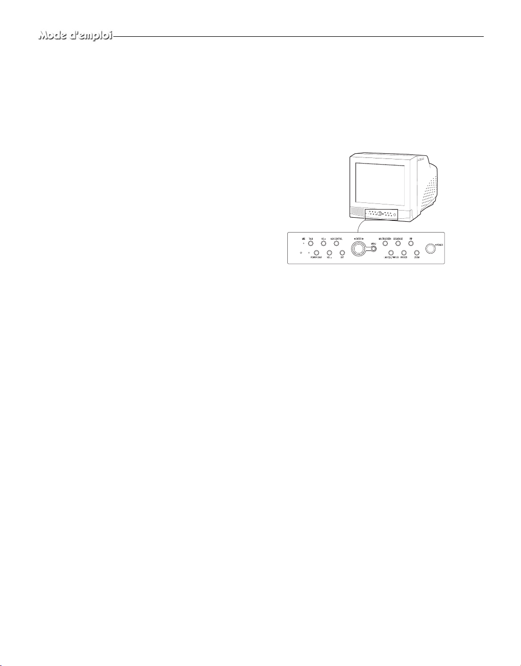
Chapter 1: Présentation
Présentation
Ce produit est un triplex qui permet d’enregistrer avec un seul magnétoscope des signaux pouvant provenir de 8 caméras. Vous pouvez
enregistrer ces signaux successivement par image ou par intermittence et lire un canal spécifique de manière sélective. Vous pouvez
utiliser trois modes d’affichage, mode LIVE (EN DIRECT), mode
P.B. (LECTURE) et mode LIVE + P.B. (EN DIRECT + LECTURE)
sur un seul moniteur.
Fonctions et caractéristiques
• Réglage de diverses fonctions avec les boutons Menu.
• Connexion possible de 8 caméras pour des images couleur ou noir
et blanc.
• Visualisation d’images pouvant provenir de 8 caméras sur un seul
écran dans les différents modes d’affichage partagés.
• Visualisation simultanée de l’écran En direct et de l’écran Lecture
sur le même moniteur.
• Agrandissement d’un écran jusqu’à 2 X grâce à la fonction Zoom.
• Utilisation de la fonction Détection de mouvement intégrée à une
caméra.
• Contrôle simultané d’un écran spécifique dans un écran principal à
l’aide de la fonction Spot Display (Affichage en incrustation).
• Visualisation de l’écran principal simultanément sur un moniteur
supplémentaire avec la fonction Slave Display (Affichage auxiliaire).
• Visualisation d’écrans en mode figé grâce à la fonction Freeze
(Gel).
• Changement et visualisation de canaux de manière successive en
mode Séquence.
• Masquage des écrans en cours d’affichage avec la fonction MASQUER CAMERA.
• L’appareil possède des voyants Date, Temps et Alarme qui peuvent
être réinitialisés.
• Lorsqu’une alarme se déclenche, le mot “EVENEMENT” s’affiche
à l’écran et un son d’alerte est émis. Le cas échéant, vous pouvez
appuyer sur Enter (au centre des boutons disposés en cercle), et
jusqu’à 16 images avant et après l’émission de l’alarme seront réaffichées dans la fenêtre Event Replay (Relecture d’événement).
L’historique des alarmes est enregistré dans LISTE DES EVENEMENTS. La fonction Alarme est utilisable seulement si le boîtier
d’alarme est connecté.
• Lorsque la fonction Channel Loss Detection (Détection de perte de
canal) détecte une perte de canal, le mot “EVENEMENT” s’affiche à l’écran et un son d’alerte est émis. Le cas échéant, vous
pouvez appuyer sur ENTER (au centre des boutons disposés en
cercle), et jusqu’à 16 images avant et après la détection de la perte
de canal sont réaffichées dans la fenêtre Event Replay ....(Relecture
d’événement). L’historique des pertes de canaux est enregistré dans
LISTE DES EVENEMENTS.
• Grâce à la fonction Door Bell Interlock (Verrouillage de la sonnette
de porte), lorsque la sonnette de porte est actionnée, l'image
actuelle passe à l'image de surveillance de la zone de la sonnette de
porte, en mode plein écran, accompagné d'un signal d'alarme. Une
image instantanée est alors mémorisée dans la “DOOR BELL
LIST” (LISTE DES APPELS). Dans la “DOOR BELL LIST”
(LISTE DES APPELS), vous pouvez mémoriser jusqu'à 8 images.
Vous pouvez accéder à l'affichage à l’écran de n'importe quelle
image mémorisée. La fonction Door Bell “Sonnette de porte” n'est
disponible que si une sonnette de porte est branchée.
Nom et fonctions des éléments
Façade/Télécommande
A. Interrupteur d’alimentation
Met l’appareil sous tension/hors tension.
B. POWER SAVE
Passe en mode Power Save (Economie d’énergie).
C. VOLUME +/-
Règle le volume.
D. TALK
Communique avec la sonnette en mode duplex.
E. AUX CONTROL
Transmet des impulsions de relais vers un périphérique pendant une
durée spécifiée. Vous pouvez régler cette commande en fonction de
votre environnement. (Par exemple, lorsque la sonnette retentit, vous
pouvez déplacer la caméra correspondante et vérifier l’identité du visiteur avant d’ouvrir la porte, à l’aide du bouton AUX CONTROL.)
F. LIVE/P.B./TRIPLEX
Change le mode d’affichage. A chaque actionnement de ce bouton, le
mode d’affichage passe successivement du mode Live (En direct), au
mode P.B. (Lecture) et au mode Triplex (Triplex).
G. SET
Donne accès au sous-menu sélectionné dans le Menu de Base.
H. BOUTONS DISPOSES EN CERCLE (LEFT, RIGHT, ENTER)
Appuyez sur le bouton LEFT pour orienter la caméra vers la gauche,
et sur le bouton RIGHT pour l’orienter vers la droite. Le bouton
ENTER est au centre. Utilisez ces boutons disposés en cercle pour
déplacer un écran auquel est appliqué un zoom avant ou pour parcourir les éléments du menu ou les canaux. Appuyez sur ENTER pour
sélectionner un élément, entrer dans un sous-menu ou revoir un événement.
Fra-4
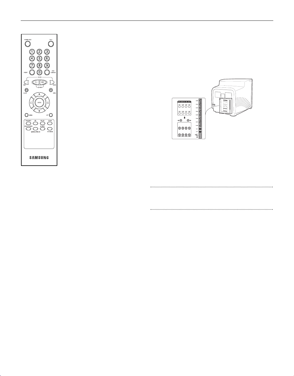
Fra-5
I. MENU
Affiche le menu INSTALLATION à l’écran.
Appuyez une nouvelle fois sur ce bouton pour
quitter le menu INSTALLATION.
J. MULTISCREEN
Commute sur l’affichage de l’écran partagé. A
chaque actionnement de ce bouton, l’affichage
de l’écran passe successivement d’une
mosaïque en 4 parties, à une mosaïque en 8
parties puis en 9 parties. Seules les mosaïques
en 9 et 16 parties sont utilisables en mode
Triplex (Triplex).
K. SEQUENCE
L’actionnement de ce bouton en mode plein
écran change les canaux automatiquement et
de manière séquencielle pendant une durée
spécifiée.
L. FREEZE
Capture l’écran sélectionné en tant qu’écran
figé. Reportez-vous à la section “Pour une
visualisation en mode FREEZE Screen (GEL
l’écran)” à la page Fra-7.
M. PIP
Sélectionne le mode Picture in Picture
(Image dans l’image).
N. ZOOM
L’actionnement de ce bouton en mode plein écran agrandit l’écran.
Chaque actionnement de ce bouton agrandit successsivement l’écran
de deux fois, puis revient à la taille normale. Utilisez les boutons disposés en cercle pour déplacer l’écran auquel est appliqué un zoom
avant.
O. Number Key (Pavé numérique) (0 ~ 9)
Appuyez sur le numéro du canal souhaité pour le visualiser en mode
plein écran. Ou appuyez sur le bouton SYSTEM ID, puis sur le
numéro de l’appareil que vous voulez régler à l’aide de la télécommande.
P. ZOOM(TELE/WIDE)
Seule la télécommande comporte ce bouton. Il n’est utilisable que si
une caméra (SOC-420(P) ou SOC-920(P), vendues séparément) est
reliée à votre appareil.
Q. FOCUS(FAR/NEAR)
Seule la télécommande comporte ce bouton. Il est destiné à la mise
au point d’une caméra et n’est utilisable que si une caméra (SOC420(P) ou SOC-920(P), vendues séparément) est reliée à l’appareil.
R. IRIS(CLOSE/OPEN)
Seule la télécommande comporte ce bouton. Il est destiné au réglage
du diaphragme d’une caméra et n’est utilisable que si une caméra
(SOC-420(P) ou SOC-920(P), vendues séparément) est reliée à l’appareil.
S. ONEAF
Effectue la mise au point automatique de la caméra sélectionnée une
fois celle-ci placée à l’état actuel. Seule la télécommande comporte ce
bouton. Il n’est utilisable que si une caméra (SOC-420(P) ou SOC920(P), vendues séparément) est reliée à l’appareil.
T. SYSTEM ID
Sélectionne l’appareil à régler avec la télécommande. Seule la télécommande comporte ce bouton.
U. ID RESET
Ce bouton, situé sur la télécommande, réinitialise l’identification du
système sélectionnée sur l’identification par défaut (1).
Panneau arrière
A. CAMERA IN(RJ-45)
Bornes d’entrée pour caméras vidéo. Vous pouvez connecter
jusqu’à 8 caméras à l’aide de connecteurs RJ-45.
B. CAMERA IN (BNC)
Bornes d’entrée pour caméras vidéo. Vous pouvez connecter
jusqu’à 8 caméras à l’aide de connecteurs BNC.
Avertissement
Les caméras de type RJ-45 ou BNC doivent être connectées sur le
même canal. Des interférences de signaux se produiront si vous connectez deux types de caméra sur le même canal.
C. VCR
• Se connecte au magnétoscope avec un connecteur 5 broches.
• TRIGGER : Borne de sortie de déclenchement pour le magnétoscope
• VIDEO IN/OUT : Borne d’entrée/sortie vidéo pour le magnétoscope
• AUDIO IN/OUT : Borne d’entrée/sortie audio pour le magnétoscope
D. AUX
• Se connecte à un autre appareil avec le connecteur 3 broches.
• SPOT VIDEO OUT : Borne permettant de contrôler le canal spécifié
dans l’écran principal sur le moniteur connecté supplémentaire.
• SPOT AUDIO OUT : Borne permettant d’écouter le son du canal
spécifié sur le moniteur connecté supplémentaire.
• SLAVE VIDEO OUT : Borne permettant de visualiser l’écran principal affiché à l’heure actuelle sur le moniteur connecté supplémentaire.
E. ALARM
• A/O (HOT/COLD) : Lors du déclenchement d’une alarme, le signal
Active Make (Actif) est émis.
• A/R : Se connecte à la borne Alarm Reset (Réinitialisation alarme)
du magnétoscope. Lors du déclenchement d’une alarme, une impulsion est émise.
• G : Se connecte à la borne de mise à la terre du magnétoscope.
F. ~AC IN
Pour brancher le cordon d’alimentation.
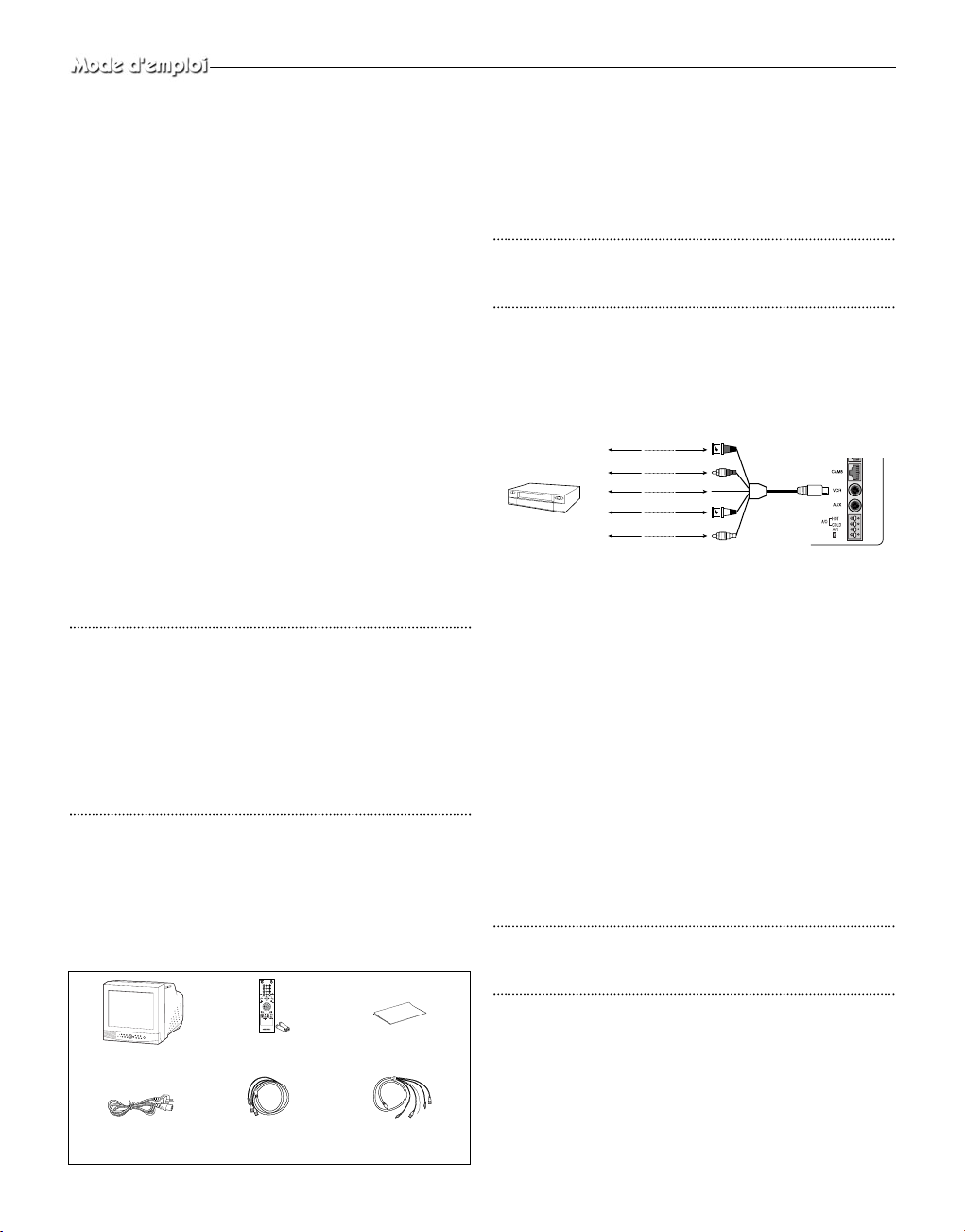
Chapter 2: Installation
Environnements de l’installation
Cette section décrit les exigences en matière d’environnement pour une
installation et une utilisation sûres. Installez le produit sur une table plate
ou dans une étagère. Ne l’utilisez qu’en position horizontale et jamais
verticale ou oblique. L’endroit où est installé l’appareil principal et la
configuration de l’espace de câblage sont très importants pour le bon
fonctionnement de l’appareil. Lorsque ces produits sont installés trop
près les uns des autres ou dans un lieu mal ventilé, le système peut ne pas
fonctionner correctement et il peut s’avérer difficile de l’entretenir.
Prévoyez une circulation d’air suffisante dans la pièce où est utilisé le
système et fermez hermétiquement le couvercle de l’appareil principal
afin d’éviter un dysfonctionnement et des pannes dues à des raisons environnementales.
Certains éléments internes sont soumis à de hautes tensions.
N’ouvrez pas le couvercle de manière inconsidérée.
Installez l’appareil dans un endroit répondant aux conditions d’environnement suivantes. Maintenez l’appareil dans les conditions de température et d’humidité indiquées ci-dessous
• Température de fonctionnement : 0˚C~40˚C
• Température de stockage : -20 °C ~ 60 °C
• Humidité au cours du fonctionnement : 20% ~ 85% RH
• Humidité de stockage : 20% ~ 95 RH
• Tension d’entrée : AC 100 ~ 240V
• Fréquence : 50/60 Hz
Avertissement
Lors de l’utilisation de ce produit, la fluctuation de la tension d’entrée ne
doit pas excéder 10 % de la tension nominale et la prise d’alimentation
externe doit être mise à la terre, afin d’éviter des décharges électriques ou
un dysfonctionnement de l’appareil. Ne branchez pas d’appareils
générant de la chaleur tels qu’un sèche-cheveux, un fer à repasser ou un
réfrigérateur sur la même prise d’alimentation que le présent appareil,
afin d’éviter son dysfonctionnement ou un incendie. L’utilisation d’un
régulateur automatique de tension est fortement recommandée afin d’assurer une alimentation stable. Placez un tore magnétique autour du connecteur pour réduire les interférences électromagnétiques.
Déballage
Retirez le couvercle de l’emballage et placez l’appareil sur une surface plane et sans risque ou à l’endroit prévu pour l’installation.
Vérifiez que tous les éléments et accessoires suivants accompagnent
l’appareil principal.
Chapter 3: Connexion à des périphériques
Le produit peut être connecté à des périphériques tels qu’un moniteur, un
magnétoscope, un boîtier d’alarme, un boîtier de sonnette, etc.
Ce chapitre décrit comment effectuer les liaisons à des périphériques.
Avertissement
Ve illez à ce que la tension d’entrée provenant d’une caméra, d’une source
vidéo ou audio, ne dépasse pas 2 V afin d’éviter un dysfonctionnement
de l’appareil.
1. Connexion à un magnétoscope à enregistrement par intervalles (ou à un magnétoscope standard)
1) Connectez la prise à 6 broches à la borne VCR (magnétoscope)
sur le panneau arrière.
2) Connectez la prise VIDEO OUT à la borne VIDEO IN du magnétoscope.
3) Connectez la prise VIDEO IN à la borne VIDEO OUT du magnétoscope.
4) Connectez la prise AUDIO OUT à la borne AUDIO IN du magnétoscope.
5) Connectez la prise AUDIO IN à la borne AUDIO OUT du magnétoscope.
6) Connectez la prise TRIGGER à la borne REC TRIGGER OUT du
magnétoscope.
7) Connectez la borne A/O (HOT) du panneau arrière à la borne
Alarme IN du magnétoscope.
8) Connectez la borne A/O (COLD) du panneau arrière à la borne
Ground (Terre) du magnétoscope.
9) Connectez la borne A/R du panneau arrière à la borne Alarme
Reset du magnétoscope.
10) Connectez la borne G (borne de mise à la terre) du panneau
arrière à la borne Ground du magnétoscope.
Avertissement
Le nom de la borne REC TRIGGER OUT ou Alarm peut varier selon le
type de magnétoscope à enregistrement par intervalles. Vérifiez le nom
des bornes avant d’effectuer les branchements.
2. Connexion du capteur d’alarme
Reliez le boîtier d’alarme et le capteur d’alarme en vous reportant au
manuel d’utilisation du boîtier d’alarme.
3. Connexion du boîtier de sonnette
Reliez les caméras et le boîtier de sonnette en vous reportant au
manuel d’utilisation du boîtier de sonnette.
Liaison auxiliaire à
6 broches(VCR)
Cordon d’alimentation
Liaison auxiliaire à
4 broches(AUX)
Télécommande/
Piles
Colorer le Moniteur
Manuel d'utilisation
VIDEO IN
MAGNÉTOSCOPE
DE FAUTE DE
TEMPS OU
MAGNÉTOSCOPE
NORMAL
VIDEO OUT
AUDIO IN
AUDIO OUT
VIDEO OUT
VIDEO IN
AUDIO OUT
AUDIO IN
TRIGGER OUT
TRIGGER
Fra-6
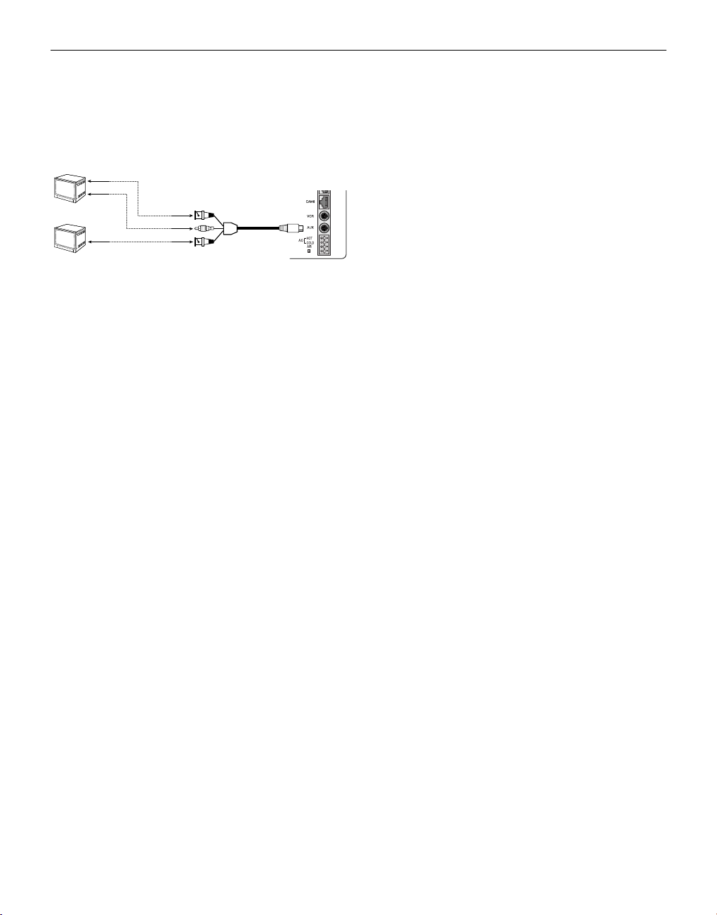
4. Connexion du moniteur standard
Reliez le moniteur standard à la borne de sortie Spot (Incrustation),
ce qui vous permet de contrôler un canal spécifié dans l’écran principal. Reliez le moniteur auxiliaire à la borne de sortie, ce qui vous
permet de visualiser en simultané la situation actuelle.which allows
you to simultaneously view the current situation .
Chapter 4:
Fonctionnement de base
1. Fonctionnement de base
1) TPlacez l’interrupteur d’alimentation en état de mise sous tension.
Lors de la première mise sous tension, les mosaïques en 9 parties
s’affichent sur le moniteur. A ce moment-là, les canaux sans entrée
s’affichent sous la forme d’un écran bleu et une perte vidéo se
produit. (Une fois la configuration initiale terminée, les paramètres
sont mémorisés y compris après coupure de l’alimentation. C’est
pourquoi, lors de la remise sous tension, l’appareil fonctionne
avec les paramètres précédents.)
2) Sélectionnez le mode d’affichage
• Mode Full Screen (Plein écran) : Si vous êtes dans un écran
partagé, allez jusqu’au canal souhaité à l’aide des boutons disposés en cercle et appuyez sur le bouton ENTER situé en son
centre. Le canal sélectionné s’affiche alors en mode Full Screen
(Plein écran).
• Mode Multi Screen (Multi-écrans) : Appuyez sur le bouton
MULTISCREEN pour afficher les écrans partagés. Vous pouvez
sélectionner les canaux à afficher sur l’écran partagé.
• Mode Sequence Screen (Ecran Séquence) : Appuyez sur le bou-
ton SEQUENCE. Les canaux passent automatiquement et successivement en mode plein écran.
• Mode Freeze Screen (Gel l’écran) : Vous pouvez capturer et
visualiser un écran figé à l’aide du bouton FREEZE et des boutons disposés en cercle.
• Mode LIVE/P.B. Screen (Ecran EN DIRECT/LECTURE) : Vous
pouvez contrôler les signaux des caméras actuelles ou lire les
écrans enregistrés à l’aide du bouton LIVE/P.B./TRIPLEX.
• Mode TRIPLEX Screen (Ecran TRIPLEX) : Vous pouvez visu-
aliser les signaux des caméras actuelles et les écrans enregistrés
sur le même moniteur grâce au bouton LIVE/P.B./TRIPLEX.
• Mode PIP Screen (Ecran PIP) : Vous pouvez visualiser les écrans
Image dans l’image (PIP) à l’aide du bouton PIP.
• Mode Zoom Screen (Ecran Zoom) : Vous pouvez agrandir un
plein écran deux fois avec le bouton Zoom et les boutons disposés en cercle.
2. Pour une visualisation sur un écran
LIVE/P.B./TRIPLEX (EN DIRECT/LECTURE/TRIPLEX).
Sélectionnez le mode écran LIVE (EN DIRECT), P.B. (LECTURE),
ou TRIPLEX (TRIPLEX) à l’aide du bouton LIVE/P.B./TRIPLEX.
A chaque actionnement de ce bouton le mode d’écran passe successivement du mode LIVE (EN DIRECT), au mode P.B. (LECTURE)
et au mode TRIPLEX (TRIPLEX).
Le bouton LIVE/P.B./TRIPLEX ne fonctionne pas dans les cas
suivants :
• Lors de l’utilisation du menu INSTALLATION
• Lors de l’affichage de la Liste des événements ou de la Liste des ...
APPELS
• Lors de la relecture des événements
• Lors de l’application d’un zoom avant à l’écran
• Lors du réglage d’un écran figé en mode multi-écrans
3. Pour une visualisation en mode Full Screen
(Plein écran)
ISi vous êtes sur un écran partagé, utilisez les boutons disposés en
cercle pour atteindre le canal souhaité et appuyez sur ENTER. La
chaîne sélectionnée s’affiche en mode Full screen (Plein écran). A cet
instant, vous pouvez changer de canal à l’aide des boutons disposés
en cercle. Vous pouvez également changer de chaîne en appuyant sur
les touches numériques de la télécommande.
4. Pour une visualisation en mode Sequence
Screen (Ecran Séquence).
L’ écran Sequence (Séquence) n’est utilisable qu’en mode LIVE (EN
DIRECT) plein écran. Lorsque l’écran est en mode LIVE (EN
DIRECT) plein écran, appuyez sur le bouton SEQUENCE pour passer à l’écran Sequence (Séquence). Vous pouvez régler les intervalles
de commutation dans “SEQUENCE” (SEQUENCE) sous “4.
REGLAGE SYSTEME” du menu INSTALLATION. La plage des
intervalles de commutation va de 1 à 30 secondes. Appuyez de nouveau sur le bouton SEQUENCE pour gel l’écran affiché actuellement.
Le bouton SEQUENCE ne fonctionne pas dans les cas suivants :
• Lors du fonctionnement en mode P.B. (LECTURE) ou TRIPLEX ..
(TRIPLEX)
• Lors de l’utilisation du menu INSTALLATION
• Lors de l'affichage d'un écran partagé
• Lors de l’affichage de la Event List (Liste des événements( ou de ..
la Liste des APPELS
• Lors de la relecture des événements
• Lors de l’application d’un zoom avant à l’écran
5. Pour une visualisation en mode FREEZE
Screen (GEL l’écran)
Vous pouvez gel temporairement un écran entier ou partagé et visualiser l’écran figé en mode LIVE (EN DIRECT), P.B. (LECTURE),
TRIPLEX (TRIPLEX). Vous pouvez sélectionner et gel des canaux
souhaités en mode d’écran partagé.
1) Affichage plein écran
Si vous appuyez sur le bouton FREEZE, l'affichage actuel se fige,
et l'icône FREEZE apparaît en haut à droite de l'écran. Appuyez
de nouveau sur le bouton FREEZE pour quitter ce mode.
Fra-7
VIDEO IN
AUDIO
IN
SPOT VIDEO OUT
SPOT AUDIO OUT
SLAVE VIDEO OUT
VIDEO IN

Fra-8
2) Affichage multi-écrans
! Si vous appuyez sur le bouton FREEZE, l'icône FREEZE
apparaît en haut à droite de l'écran.
@ Passez à l'image que vous souhaitez figer à l'aide des boutons
disposés en cercle.
# Si vous appuyez sur le bouton ENTER situé au centre des
boutons disposés en cercle, l'image obtenue par ce canal se
fige, et la lettre “F” apparaît. Appuyez de nouveau sur le bouton ENTER pour quitter ce mode.
$ Si vous voulez voir l'image figée depuis un autre canal,
passez au canal cible, et appuyez sur ENTER. L'image du
nouveau canal se fige, et la lettre “F” apparaît. Appuyez de
nouveau sur le bouton ENTER pour quitter ce mode.
% Si l'image sur un autre canal reste figée, répétez l'étape
$
.
^ Appuyez sur le bouton FREEZE pour quitter complètement
le mode FREEZE (GEL).
Le bouton FREEZE ne fonctionne pas dans les cas suivants :
• Lors de l’utilisation du menu INSTALLATION
• Lors de l’affichage de la Liste des événements ou de la Liste
des APPELS
• Lors de la relecture des événements
6. Pour une visualisation en mode ZOOM
Screen (Ecran ZOOM)
Ce mode est utilisé uniquement en Mode LIVE/P.B. Full Screen
(Plein écran EN DIRECT/LECTURE).
1) Lorsque vous appuyez sur le bouton ZOOM, une ZOOM AREA
(ZONE DE ZOOM) apparaît au centre de l'écran.
2) Déplacez la ZOOM AREA <ZONE DE ZOOM> vers la position
cible à l'aide des boutons disposés en cercle et du bouton
ENTER.
3) Appuyez de nouveau sur le bouton ZOOM pour agrandir l'image
jusqu'à doubler sa dimension d'origine.
4) Appuyez de nouveau sur ce bouton pour revenir à la dimension
d'origine.
Déplacement de ZOOM AREA (ZONE DE ZOOM) et de l'image
ZOOM
1) Appuyez sur le bouton ZOOM et actionnez les boutons disposés
en cercle pour déplacer la ZOOM AREA (ZONE DE ZOOM)
vers le haut et vers le bas au-dessus de l'image.
2) Appuyez sur le bouton ENTER et actionnez les boutons disposés
en cercle pour déplacer la ZOOM AREA (ZONE DE ZOOM)
vers la gauche et vers la droite au-dessus de l'image.
3) Appuyez de nouveau sur le bouton ENTER et actionnez les boutons disposés en cercle pour déplacer la ZOOM AREA (ZONE
DE ZOOM) vers le haut et vers le bas au-dessus de l'image.
Le bouton ZOOM ne fonctionne pas dans les cas suivants :
• Lors de l’utilisation du menu INSTALLATION
• Lors de l’affichage de la Liste des événements ou de la Liste des
APPELS
• Lors de la relecture des événements
• Lors du fonctionnement en mode Séquence
7. Pour une visualisation en mode PIP Screen
(Ecran PIP) (Image dans l’image).
Vous pouvez visualiser un écran Image dans l’image en mode LIVE
(EN DIRECT) plein écran à l’aide du bouton PIP.
La première fois où vous appuyez sur le bouton PIP, l’écran secondaire
qui s’affiche sur l’écran PIP est un écran Séquence. Puis, après le retour
en mode PIP, l’écran secondaire qui s’affiche dans le même mode
d’écran que celui utilisé au moment où vous avez précédemment quitté le
mode PIP.
Utilisation de l’écran PIP
1) Appuyez sur le bouton PIP en mode LIVE <EN DIRECT> plein
écran.
2) Lorsqu’un canal figé s’affiche sur l’écran secondaire, chaque fois
que vous appuyez sur le bouton ENTER, ce canal commute entre
l’écran principal et l’écran secondaire.
3) Actionnez les boutons disposés en cercle pour changer le canal de
l’écran principal.
4) Appuyez sur le bouton SEQUENCE pour régler l’écran secondaire en tant qu’écran Séquence. Appuyez de nouveau sur ce
bouton pour régler le canal.
5) Vous pouvez changer la position de l’écran secondaire dans
“POSITION PIP” sous “2.REGLAGE HORLOGE” du menu
INSTALLATION.
Le bouton PIP ne fonctionne pas dans les cas suivants :
• Lors du fonctionnement en mode P.B. (LECTURE) ou TRIPLEX
(TRIPLEX)
• Lors de l'affichage d'un écran partagé
• Lors de l’utilisation du menu INSTALLATION
• Lors de l’affichage de la Event List (Liste des événements) ou de la
Liste des APPELS
• Lors de la relecture des événements
• Lors de l’application d’un zoom avant à l’écran
• Lors du fonctionnement en mode Séquence
• En l’absence de toute entrée de signal vidéo
• Lorsque le canal du signal d’entrée est en mode plein écran lors de
l’entrée vidéo unique
8.
Pour une visualisation de la sortie magnétoscope.
Passez au mode PB FULL (LECTURE PLEIN ECRAN) en
appuyant sur le bouton Live/P.B./TRIPLEX. L'image “PB
THROUGH” (EN COURS DE LECTURE) apparaît si vous
appuyez sur le bouton ENTER dans ce mode. Appuyez de nouveau sur le bouton “ENTER” pour revenir à l'image PB (LECTURE) précédente.
Avertissement
Cette fonction est disponible uniquement en mode PB FULL
Display (LECTURE Affichage PLEIN ECRAN).
9. Pour une visualisation de l’écran Event
Replay (Relecture d’événement)
1) Lors de l’entrée d’un signal Alarm/Motion
(Alarme/Mouvement)
YVous pouvez utiliser la fonction d’alarme uniquement si un
boîtier d’alarme est connecté. Lors de l’entrée d’un signal
d’alarme/de mouvement, « EVENEMENT » s’affiche à l’écran et
un son d’alerte est émis. Le cas échéant, si vous appuyez sur le
bouton ENTER, jusqu'à 16 images avant et après l'émission du
signal d’alarme/de mouvement sont réaffichées dans la fenêtre
Event Replay (Relecture d'événement).
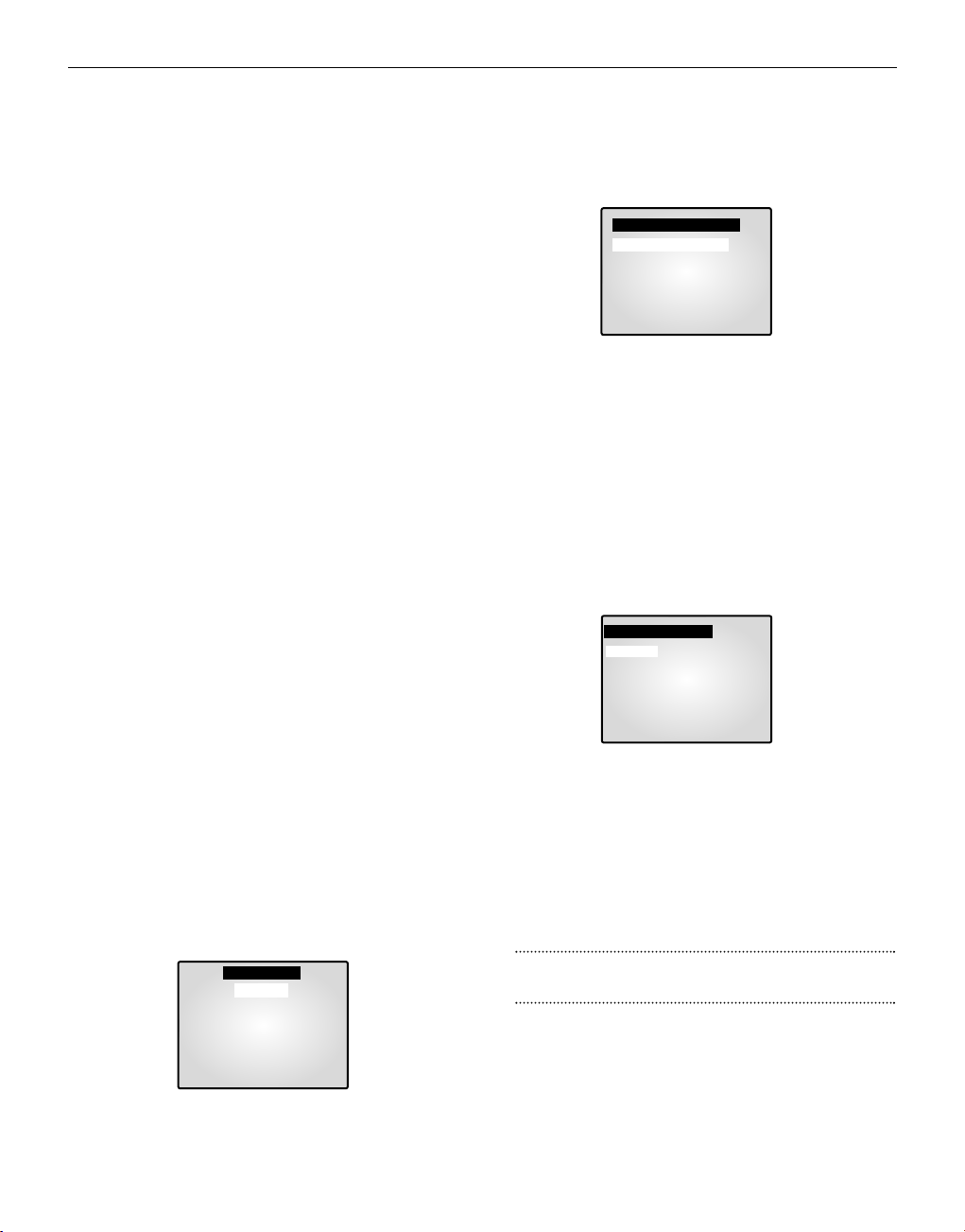
Appuyez de nouveau sur ENTER pour arrêter la relecture de
l’événement. Si des signaux d’alarme/de mouvement entrent sur
plusieurs canaux, appuyez sur ENTER pour démarrer la relecture
de l’événement sur un autre canal à la fin de la relecture de
l’événement actuel. Une fois terminé la relecture de l’événement
pour tous les canaux sur lesquels un signal d’alarme/de mouvement
a été émis, appuyez sur ENTER pour quitter le mode Event Replay
(Relecture d’événement). L’historique des alarmes/des mouvements est enregistré dans la LISTE DES EVENEMENTS.
2) Lors d’une détection de perte de canal
Si la fonction de détection de perte de canal détecte une perte de
canal, le mot “EVENEMENT” s'affiche à l'écran et un son d'alerte
est émis. Le cas échéant, si vous appuyez sur le bouton ENTER,
jusqu'à 16 images avant et après la perte de canal détectée sont
réaffichées dans la fenêtre Event Replay (Relecture d’événement).
Appuyez de nouveau sur ENTER pour arrêter la relecture de
l’événement. Si la perte de canal est détectée sur plusieurs canaux,
appuyez sur ENTER pour démarrer la relecture de l’événement pour
le canal suivant à la fin de la relecture de l'événement actuel.
Une fois terminé la relecture de l'événement pour tous les canaux sur
lesquels la perte de canal a été détectée, appuyez sur ENTER pour
quitter le mode Event Replay (Relecture d’événement). L’historique
des pertes de canaux est enregistrée dans la LISTE DES EVENEMENTS.
10. Pour la visualisation de l’écran APPELS
La fonction Door Bell <Sonnette de porte> n'est disponible que si
une sonnette de porte est branchée. Lorsque la sonnette de porte est
actionnée, l'image actuelle passe à l'image de surveillance de la
zone de la sonnette de porte, en mode plein écran, accompagné
d'un signal d'alarme. Une image instantanée est alors mémorisée
dans la “DOOR BELL LIST” (LISTE DES APPELS). Dans la
“DOOR BELL LIST” (LISTE DES APPELS), vous pouvez
mémoriser jusqu'à 8 images. Vous pouvez accéder à l'affichage à
l’écran de n'importe quelle image mémorisée. Sélectionnez l’élément souhaité dans “6. LISTE DES APPELS”du menu INSTALLATION pour l’afficher en tant qu’écran figé. Puis, appuyez de
nouveau sur ENTER pour revenir à l’écran “LISTE DES
APPELS”.
Chapter 5: Paramètres du menu installation
<MENU INSTALLATION>
• Appuyez sur le bouton MENU pour afficher l’écran Sélection de
la langue.
• Sélectionnez la langue souhaitée avec les boutons disposés en
cercle et appuyez sur ENTER pour afficher la menu INSTALLATION dans la langue souhaitée.
• Lorsque vous appuyez sur le bouton MENU après avoir sélectionné la langue initiale, l’écran Sélection de la langue n’apparaît
pas. A la place, le menu INSTALLATION suivant apparaît sur le
moniteur. Appuyez sur le bouton une nouvelle fois pour revenir
au menu précédent.
<SOUS-MENU>
• Sélectionnez l’un des sous-menus 1 à 6 dans le menu INSTALLATION à l’aide des boutons disposés en cercle et appuyez sur
ENTER pour accéder au sous-menu.
1. REGLAGE MONITEUR
Vous pouvez changer le contraste, la luminosité, la couleur, la netteté et la teinte de l’écran principal sur le moniteur.
Sélectionnez “REGLAGE MONITEUR” dans le menu INSTALLATION à l’aide des boutons disposés en cercle et appuyez sur
ENTER pour afficher l’écran suivant.
• Sélectionnez un élément à l’aide des boutons disposés en cercle
et appuyez sur ENTER pour changer la valeur préréglée.
• Changez la valeur préréglée (0 à 100) à l’aide des boutons disposés en cercle et appuyez sur ENTER pour enregistrer le
paramètre.
• Sélectionnez SAUVER (enregistrer les changements), QUITTER (quitter le mode réglage sans enregistrer) ou PRESET
(PREREGLAGE) (réinitialise tous les réglages à leur valeur par
défaut) dans le menu QUITTER et appuyez sur ENTER pour
revenir au menu INSTALLATION.
Avertissement
L'élément “TEINTE” est disponible uniquement en mode NTSC
SYSTEM(SYSTEME NTSC).
2. REGLAGE HORLOGE
Vous pouvez changer la position PIP, le type d’affichage, le type de
date et l’heure.
Sélectionnez « REGLAGE HORLOGE» dans le menu INSTALLATION à l’aide des boutons disposés en cercle et appuyez sur ENTER
pour afficher l’écran suivant :
Fra-9
[REGLAGE MONITEUR]
CONTRASTE 50
LUMIÈRE 50
COULEUR 50
NETTETÉ 50
TEINTE 50
SORTIE QUITTER
[MENU D’INSTALLATION]
1. REGLAGE MONITEUR
2. REGLAGE HORLOGE
3. REGLAGES CAMERAS
4. REGLAGE SYSTEME
5. LISTE DES EVENEMENTS
6. LISTE DES APPELS
[LANGUAGE]
ENGLISH
ESPAÑOL
FRANÇAIS
ITALIANO
DEUTSCH
NEDERLANDS
PORTUGUÊS
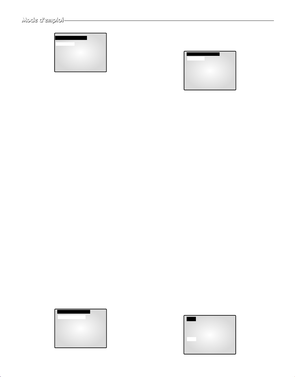
• Sélectionnez un élément à l’aide des boutons disposés en cercle et
appuyez sur ENTER pour changer la valeur préréglée.
• Changez la valeur préréglée à l’aide des boutons disposés en cercle et
appuyez sur ENTER pour enregistrer le paramètre.
• Appuyez sur le bouton MENU pour revenir au menu INSTALLATION.
POSITION PIP: INFÉRIEUR DROIT ↔ superieur gauche ↔ superieur
droit ↔ INFÉRIEUR gauche.
• Sélectionnez la position PIP parmi les quatre options ci-dessus.
TYPE D’AFFICHAGE: TOUT ↔ TITRE ↔ DATE/HEURE ↔ sans.
• TOUT: Tous les éléments s’affichent hormis DATE/HEURE et TITRE.
• TITRE: Seul l’élément CHANNEL TITLE (TITRE DU CANAL) s’affiche.
• DATE/HEURE: Seul l’élément DATE/HEURE s’affiche.
• sans: Ni DATE/HEURE ni TITRE ne s’affiche.
COULEUR DE BORD: GRIS ↔ NOIR
• GRIS : COULEUR DE LA BORDURE s’affiche en GRIS en mode
Multi-écrans.
• NOIR: COULEUR DE LA BORDURE s’affiche en NOIR en mode
Multi-écrans.
TYPE DE DATE: AA/MM/JJ ↔ MM/JJ/AA ↔ JJ/MM/AA.
DATE [AA/MM/JJ]
• Année (AA): 00(2000) ~ 99(2099)
• Mois (MM): 01 ~ 12
• Jour (JJ): 01 ~ 31
HEURE [HH:MM:SS]
• Heure (HH): 00 ~ 23
• Minute (MM): 00 ~ 59
• Seconde (SS): 00 ~ 59
3. REGLAGES CAMERAS
Vous pouvez changer les valeurs de Camera ID (Identification
Caméra), DETECTION DE PERTE, DETECTION DE MOUVEMENT et de Camera Preset (Préréglage caméra).
Sélectionnez “3. REGLAGES CAMERAS” dans le Menu de Base à
l’aide des boutons disposés en cercle et appuyez sur ENTER pour
afficher l’écran suivant.
Sélectionnez le canal souhaité avec les boutons disposés en cercle et
appuyez sur ENTER pour accéder à l’affichage du canal sélectionné.
L’ écran suivant apparaît.
• Tous les éléments, hormis “CAMÉRA ID” et “DETECTION DE
PERTE”, peuvent être réglés seulement après la connexion du système
à une caméra (SOC-420(P) ou SOC-920(P), vendues séparément).
• Sélectionnez l’élément souhaité avec les boutons disposés en cercle et
appuyez sur ENTER. Puis changez la valeur préréglée à l’aide des boutons disposés en cercle et appuyez sur ENTER pour terminer le
réglage.
• Sélectionnez SAUVER (enregistrer les changements), QUITTER (quitter le mode réglage sans enregistrer) ou PRESET (réinitialiser tous les
réglages à leur valeur par défaut) dans le menu QUITTER et appuyez
sur ENTER pour revenir au menu REGLAGES CAMERAS. Vous ne
pouvez pas revenir au menu précédent lorsque vous êtes en mode
réglage. Vous pouvez seulement revenir au menu précédent en sélectionnant QUITTER.
• Changez les valeurs préréglées des autres canaux en procédant de la
même manière.
• Appuyez sur le bouton MENU après avoir terminé tous les réglages
pour revenir au menu INSTALLATION.
CAMÉRA ID (IDENTIFICATION CAMÉRA):
---CH1----
(“- ” indique un blanc.)
• Sélectionnez CAMÉRA ID à l’aide des boutons disposés en cercle et
appuyez sur ENTER pour sélectionner le premier “- .”
• Sélectionnez le caractère souhaité à l’aide des boutons disposés en cercle et appuyez sur ENTER pour passer au caractère suivant et le sélectionner. (Ordre des caractères : 0123456789ABCDEFGHIJKLMNOPQRSTUVWXYZ[ ] ~ _ . / )
• Répétez l’opération pour sélectionner tous les caractères souhaités.
(Vous pouvez choisir jusqu’à dix caractères.)
DETECTION DE PERTE:
Marche/Arret la détection de perte.
(MARCHE ↔ ARRET).
IRIS (DIAPHRAGME):
Règle le niveau de sortie vidéo via le
diaphragme en fonction du niveau de lumière pénétrant dans la caméra.
• Sélectionnez “IRIS” à l’aide des boutons disposés en cercle et appuyez
sur ENTER pour sélectionner “ALC...” ou “MANUE”.
• ALC...: Compensation automatique de lumière (ALC)
- Sélectionnez «ALC…» avec les boutons disposés en cercle et appuyez
sur le bouton SET pour afficher l‘écran suivant. Appuyez sur le bouton
MENU après avoir terminé le réglage pour revenir au menu précédent.
Fra-10
[REGLAGES CAMÉRA 1]
CAMÉRA ID ---CH1---DETECTION DE PERTE MARCHE
IRIS ALC …
SHUTTER ARRET
BALANCE DES BLANCS ATW
SPECIAL …
FOCUS UN-AF
DETECTION DE MOUVEMENT…
SORTIE SAUVER
[ALC]
ZONE PRESET...
C-JOUR ARRET
NIVEAU[ 00 ] ----------+----------
[REGLAGES CAMERAS]
REGLAGES CAMÉRA 1 …
REGLAGES CAMÉRA 2 …
REGLAGES CAMÉRA 3 …
REGLAGES CAMÉRA 4 …
REGLAGES CAMÉRA 5 …
REGLAGES CAMÉRA 6 …
REGLAGES CAMÉRA 7 …
REGLAGES CAMÉRA 8 …
[REGLAGE HORLOGE]
POSITION PIP
INFÉRIEUR DROIT
TYPE D’AFFICHAGE TOUT
COULEUR DE BORD GRIS
TYPE DE DATE AA/MM/JJ
DATE [AA/MM/JJ] 04/01/01
HEURE [HH:MM:SS] 12:30:01
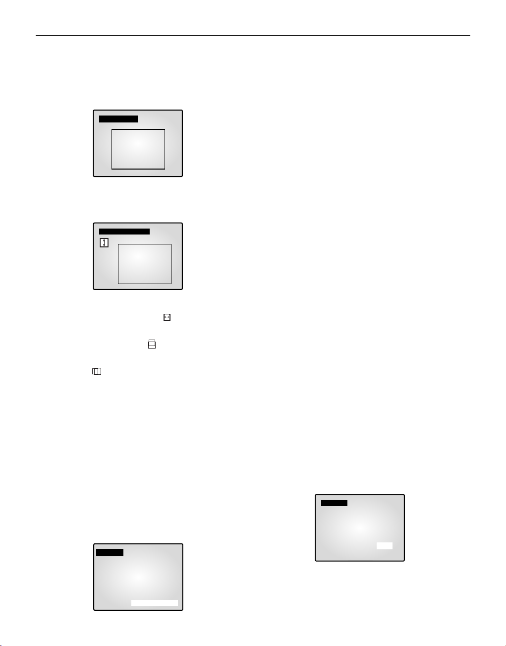
Fra-11
- Sélectionnez ZONE à l’aide des boutons disposés en cercle et appuyez
sur ENTER pour sélectionner “PRESET...” ou “UTILISATEUR...”.
- Sélectionnez “PRESET” à l’aide des boutons disposés en cercle et
appuyez sur le bouton SET pour afficher l‘écran suivant. La compensation de contre-jour s’applique à la zone/aux zones avec les valeurs
préréglées.
Appuyez sur le bouton MENU pour revenir au menu précédent.
- Sélectionnez “UTILISATEUR...” à l’aide des boutons disposés en cercle et appuyez sur le bouton SET pour
afficher l‘écran suivant.
❙ Réglez la taille en haut/en bas à l’aide des boutons disposés en cercle
et appuyez sur ENTER pour effectuer une sélection et passer au
réglage de la taille du côté gauche/droit. “ ” s’affiche alors à l’écran.
❙ Appuyez sur ENTER pour après avoir réglé la taille du côté
gauche/droit à l’aide des boutons disposés en cercle. Vous pouvez alors
régler la position en haut/en bas et “ ” s’affiche à l’écran.
❙ Appuyez sur ENTER pour régler la position à l’aide des boutons dis-
posés en cercle. Vous pouvez alors régler la position du côté
gauche/droit et “ ” s’affiche à l’écran.
❙ Appuyez sur ENTER pour régler la position à l’aide des boutons dis-
posés en cercle. Ainsi se termine le réglage de ZONE. Appuyez sur le
bouton MENU pour revenir au menu précédent.
- C-JOUR (Compensation de contre-jour) : Lorsque C-JOUR est
“MARCHE”, la fonction C-JOUR s’applique à toutes les zones réglées
dans ZONE. Lorsqu’une lumière vive se trouve en arrière-plan d’un
objet, celui-ci apparaît de manière sombre sur le moniteur en raison du
contre-jour. Pour résoudre ce problème, utilisez la fonction BLC afin
d’obtenir des images claires.
- NIVEAU: Vous pouvez régler le niveau de sortie vidéo de “ -9” à
“+9”. Sélectionnez “NIVEAU [00]” à l’aide des boutons disposés en
cercle et appuyez sur ENTER pour changer le réglage. Appuyez sur
ENTER après avoir changé le réglage, pour enregistrer ce paramètre.
• MANUEL...: Règle l’ouverture/la fermeture manuelle du diaphragme.
- Sélectionnez “MANUEL...” à l’aide des boutons disposés en cercle et
appuyez sur le bouton SET pour afficher l‘écran suivant.
- Réglez la valeur à l’aide des boutons disposés en cercle.
- Appuyez sur le bouton MENU pour revenir au menu précédent.
SHUTTER (OBTURATEUR)
- Vous pouvez régler la vitesse d’obturateur grande vitesse à contrôle
électronique, la vitesse d’obturateur lente et la vitesse d’obturateur
lente FIX.
- La vitesse d’obturateur grande vitesse à contrôle électronique peut
prendre 7 valeurs allant de 1/120(1/100) sec à 1/10K sec. La vitesse
d’obturateur lente Auto et la vitesse d’obturateur lente FIX peuvent
prendre chacune 12 valeurs allant de X2 à X128.
- La vitesse lente ralentit la vitesse de l’obturateur de sorte que les
images prises par faible lumière apparaissent plus claires à l’écran.
Sélectionnez la vitesse d’oburateur lente AUTO pour détecter la densité
de lumière et réduire automatiquement la vitesse de l’obturateur en
fonction de cette densité. Sélectionnez la vitesse d’obturateur lente
FIX pour régler manuellement la vitesse de l’obturateur.
- Les nombres qui suivent les éléments AUTO et FIX indiquent le nombre de champs mémorisés. Plus le nombre est élevé, plus la vitesse de
l’obturateur est lente. Les images figées apparaissent donc très claires.
Avec les images non figées, l’objet peut cependant apparaître de
manière trouble.
- Réglage de la valeur
Dans le menu SHUTTER (OBTURATEUR), appuyez sur ENTER pour
régler les valeurs. Sélectionnez la valeur à l’aide des boutons disposés
en cercle et appuyez sur ENTER pour terminer le réglage.
ARRET ’ 1/120(1/100) ’ 1/250 ’ 1/500 ’ 1/1000 ’1/2000 ’ 1/4000 ’
1/10K ’ ARRET ’AUTO X2 ’AUTO X4 ’ AUTO X6 ’AUTO X8 ’
AUTO X12 ’AUTO X16 ’AUTO X24 ’AUTO X32 ’ AUTO X48 ’
AUTO X64 ’AUTO X96 ’AUTO X128 ’ARRET ’ FIX X2 ’ FIX X4 ’
FIX X6 ’ FIX X8 ’FIX X12 ’ FIX X16 ’ FIX X24 ’FIX X32 ’ FIX
X48 ’ FIX X64 ’FIX X96 ’ FIX X128.
BALANCE DES BLANCS:
AT W, AWC, MANUEL...
• Vous pouvez activer la fonction BALANCE DES BLANCS qui permet
au blanc d’apparaître normalement quelle que soit la température de
couleur de la lumière.
• ATW: Contrôle le changement de la température de couleur et règle la
valeur de BALANCE DES BLANCS en conséquence.
• AWC: Règle la valeur de BALANCE DES BLANCS en fonction de la
température de couleur une seule fois et conserve ensuite cette valeur.
Lorsque l’écran AWC est affiché, placez une feuille blanche devant la
caméra et appuyez sur le bouton SET.
• MANUEL...: Sélectionnez “MANUEL” à l’aide des boutons disposés
en cercle et appuyez sur le bouton SET pour afficher l’écran suivant.
Vous pouvez alors choisir 3200K, 5600K ou Mode utilisateur et régler
manuellement l’équilibrage des blancs en fonction des conditions d’éclairage actuelles.
- 3200K : Règle la température de couleur sur 3200˚ K.
- 5600K : Règle la température de couleur sur 5600˚ K.
- Sélectionnnez «UTILISATEUR» pour afficher l’écran suivant.
Appuyez sur ENTER, puis sélectionnez les valeurs correctes de
ROUGE et BLEU pour régler manuellement la température de couleur.
[PRESET ZONE]
[ZONE UTILISATEUR]
[MANUEL]
NIVEAU[ 00 ] -------------+-------------
[MANUEL]
PRESET 3200K
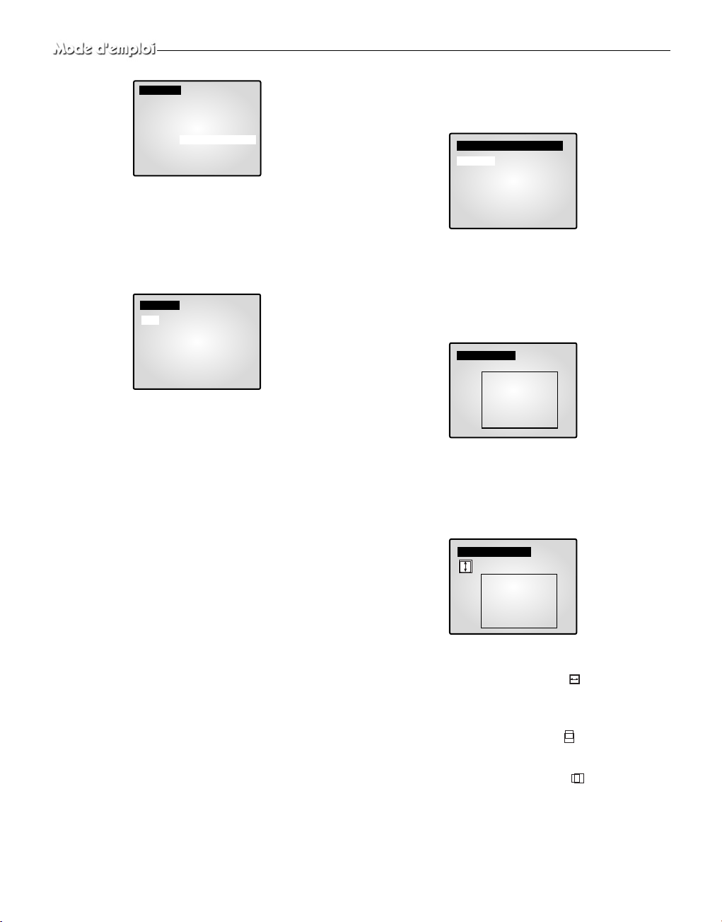
Appuyez sur le bouton MENU pour revenir au menu précédent.
SPECIAL...
• Sélectionnez «SPECIAL...» à l’aide des boutons disposés en cercle et
appuyez sur le bouton SET pour afficher l’écran suivant. Appuyez sur
le bouton MENU après avoir terminé le réglage pour revenir au menu
précédent.
• AGC: Fonction AGC (commande automatique de gain)
Marche/Arret.
• MIROIR: Inverse horizontalement les signaux d’entrée vidéo.
• D-ZOOM: Règle le taux d’agrandissement du zoom numérique.
Ce système permet un zoom jusqu’à 10X.
• POSI/NEGA: Règle les signaux de sortie vidéo sur entrée normale ou sur entrée inversée.
• VITESSE ZOOM: Règle la vitesse de déplacement du zoom.
- 1: Environ 17 sec sont nécessaires pour passer de x1 à x12
(vitesse la plus lente)
- 2: Environ 10 sec sont nécessaires pour passer de x1 à x12
(vitesse lente)
- 3: Environ 6 sec sont nécessaires pour passer de x1 à x12
(vitesse rapide)
- 4: Environ 3 sec sont nécessaires pour passer de x1 à x12
(vitesse la plus rapide)
• DETAIL: Règle la luminosité verticalement et horizontalement.
FOCUS (MISE AU POINT): Règle la mise au point FM
(Mise au point manuelle) ou UN-AF.
• FM (Mise au point manuelle) : Le mode Manual Focus (Mise au
point manuelle) permet à l’utilisateur de faire la mise au point.
• UN-AF: Lorsque le zoom passe de la position Wide (Grand angle)
à la position Telephoto (Téléobjectif), la mise au point automatique
ne se fait qu’une fois la fonction Telephoto (Téléobjectif) terminée.
- UN fonctionne comme le mode FM (Mise au point manuelle)
dans le cas d’images figées et, comme le mode AF (Mise au point
automatique), lorsque le zoom est en position Telephoto
(Téléobjectif).
DETECTION DE MOUVEMENT...
• La fonction Détection de mouvement a pour but de détecter le mouve-
ment d’un objet. En activant cette fonction, vous pouvez détecter le
mouvement d’un intrus en dehors des heures de pointe.
• Sélectionnez «DETECTION DE MOUVEMENT» à l’aide des boutons
disposés en cercle et appuyez sur le bouton SET pour afficher l’écran suivant. Appuyez sur le bouton MENU après avoir terminé le réglage pour
revenir au menu précédent.
- ZONE: Règle la zone de l’écran à laquelle s’applique le détecteur de
mouvement.
❙ Sélectionnez “PRESET” à l’aide des boutons disposés en cercle et
appuyez sur le bouton SET pour afficher l’écran suivant. La détection de mouvement s’applique à la zone/aux zones comprise(s) à
l’intérieur du cadre.
Appuyez sur le bouton MENU pour revenir au menu précédent.
- USER...
❙ Sélectionneez “UTILISATEUR…” à l’aide des boutons disposés en
cercle et appuyez sur le bouton SET pour afficher l’écran suivant.
❙ Réglez la taille en haut/en bas à l’aide des boutons disposés en cer-
cle et appuyez sur ENTER pour effectuer une sélection et passer au
réglage de la taille du côté gauche/droit. “ ” s’affiche alors à
l’écran.
❙ Réglez la taille du côté gauche/droit à l’aide des boutons disposés en
cercle et appuyez sur ENTER pour effectuer une sélection et passer
au réglage de la position en haut/en bas. “ ” s'affiche à l'écran.
❙ Réglez la position en haut/en bas à l’aide des boutons disposés en cer-
cle et appuyez sur ENTER pour effectuer une sélection et passer au
réglage de la position du côté gauche/droit. “ ” s’affiche à l’écran.
❙ Réglez la position du côté gauche/droite avec les boutons disposés
en cercle et appuyez sur ENTER. Ainsi se termine le réglage de
ZONE. Appuyez sur le bouton MENU pour revenir au menu
précédent.
• SENSIBILITE: Règle la sensibilité du détecteur de mouvement sur
BAS, MOYEN ou HAUT.
[MANUEL]
PRESET ARRET[UTILISATEUR]
ROUGE [ 00 ] --------+-------BLEU [ 00 ] --------+--------
[SPECIAL]
AGC MARCHE
MIRROIR ARRET
D-ZOOM ARRET
POSI/NEGA +
VITESSE ZOOM 3
DETAIL [ 0 ] -------+-------
Fra-12
[DETECTION DE MOUVEMENT]
ZONE PRESET…
SENSIBILITE MOYEN
[PRESET ZONE]
[ZONE UTILISATEUR]
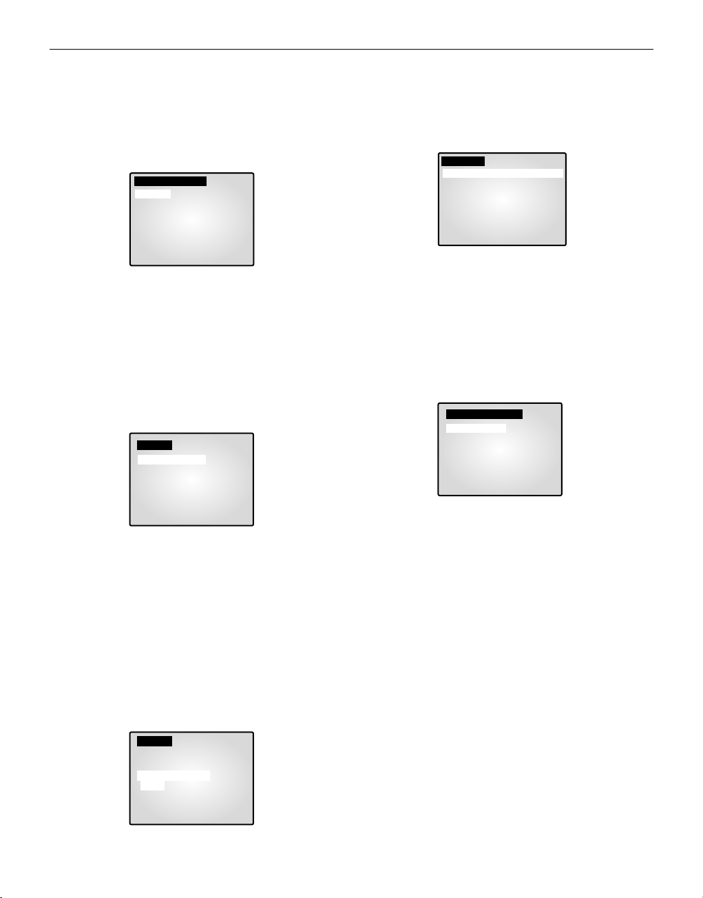
4. REGLAGE SYSTEME
Vous pouvez changer les paramètres de ALARME, D’ENREGISTREMENT, MASQUER CAMERA, SEQUENCE, SYSTEME ID,
PASSE et SÉLECTION DE LANGUE. Sélectionnez “4. REGLAGE
SYSTEME” dans le menu INSTALLATION à l’aide des boutons disposés en cercle et appuyez sur ENTER pour afficher l’écran suivant.
- Sélectionnez un élément à l’aide des boutons disposés en cercle et
appuyez sur ENTER pour changer le réglage.
- Changez le réglage à l’aide des boutons disposés en cercle et
appuyez sur ENTER pour l’enregistrer.
- Appuyez sur le bouton MENU après avoir terminé tous les
réglages pour revenir au menu INSTALLATION.
ALARME…
• Sélectionnez “ALARME” à l’aide des boutons disposés en cercle et
appuyez sur ENTER pour afficher l’écran suivant.
TEMPS D’ALARME
TEMPS D’ALARME correspond à la durée pendant laquelle l’alarme continue. Vous pouvez réglez la durée de maintien sur 5 sec, 15 sec, 30 sec, 1
min, 3 min, 5 min, 10 min, 20 min, 30 min ou sur AUTO. Si vous sélectionnez AUTO, l’alarme reste activée pendant toute la durée du signal
d’alarme.
BUZZER D’ALARME
Lors du déclenchement de l’alarme, le bruiteur d’alarme retentit. Vous
pouvez régler la durée sur 5 sec, 15 sec, 30 sec 1 min ou sur NO. Si vous
sélectionnez NO, le bruiteur d’alarme ne retentit pas.
• Sélectionnez “FORME D’ ALARME” à l’aide des boutons disposés en
cercle et appuyez sur le bouton SET pour afficher l’écran suivant.
• Vous pouvez sélectionner le moment où l’alarme s’arme ou se désarme
en fonction de deux modèles. Si vous sélectionnez FORME A, la durée
de FORME B est modifiée automatiquement.
• Sélectionnez FORME A à l’aide des boutons disposés en cercle et
appuyez sur ENTER pour afficher l’écran suivant.
• Choisissez Marche/Arret pour les fonctions Mouvement, Alarme et
Appel de chacune des 8 caméras.
• Appuyez sur le bouton MENU après avoir terminé les réglages pour
revenir au menu ALARME.
• Répétez l’opération pour FORME B.
• Le “--” sera affiché en l’absence de connexion aux accessoires.
D’ENREGISTREMENT...
• Sélectionnez “D’ENREGISTREMENT” à l’aide des boutons disposés
en cercle et appuyez sur ENTER pour afficher l’écran suivant.
TYPE D’ENREGISTREMENT
• NOR : Utilisé pour effectuer un enregistrement avec un magnétoscope
standard. L'image est affichée en fonction des valeurs définies pour le
“DEBUT D'ENRE-GISTREMENT” (champ, ENCADREMENT).
• TLV: Utilisé pour effectuer un enregistrement avec un magnétoscope à
enregistrement par intervalles.
DÉ BUT D’ENREGISTREMENT
Il est valide lorsque le TYPE D'ENREGISTREMENT est “NOR”.
• CHAMP : Enregistrement à 1/50ème de seconde (PAL), 1/60ème de
seconde (NTSC).
• ENCADREMENT :Enregistrement à 1/25ème de seconde (PAL),
1/30ème de seconde (NTSC).
ENR AUDIO
Règle le canal qui transmet des signaux audio vers la sortie d’enregistrement.
SORTIE SPOT
Règle le canal de sortie SPOT (INCRUSTATION) qui contrôlera ce canal
de manière intensive.
• Appuyez sur le bouton MENU après avoir terminé les réglages pour
revenir au menu REGLAGE SYSTEME.
Fra-13
[REGLAGE SYSTEME]
ALARME…
D’ENREGISTREMENT…
MASQUER CAMERA…
SEQUENCE 02 [ SEC]
SYSTEME ID 1
TEST MOT DE PASSE ARRET
CHANGE. M. PASSE …
SÉLECTION DE LANGUE FRANÇAIS
[ALARME]
TEMPS D’ALARME 01 [MIN]
BUZZER D’ALARME 05 [SEC]
FORME D’ ALARME …
[ALARME]
TEMPS D’ALARME 01 [MIN]
BUZZER D’ALARME 05 [SEC]
FORME D’ ALARME …
TEMPS 08:00 - 17:00 [FORME A]
17:00 - 08:00 [FORME B]
FORME A …
FORME B …
[FORME A]
CH MOUVEMENTALARME APPEL
CH1 ARRET -- ARRET
CH2 ARRET -- -CH3 -- ARRET ARRET
CH4 ARRET ARRET ARRET
CH5 ARRET ARRET ARRET
CH6 ARRET ARRET ARRET
CH7 ARRET ARRET ARRET
CH8 ARRET ARRET ARRET
[D’ENREGISTREMENT]
type d’enregistrement NOR
DÉ BUT d’enregistrement ENCADREMENT
ENR AUDIO CH1
SORTIE SPOT CH1
 Loading...