

Samsung SMO-150TP, SMO-210TP User Manual
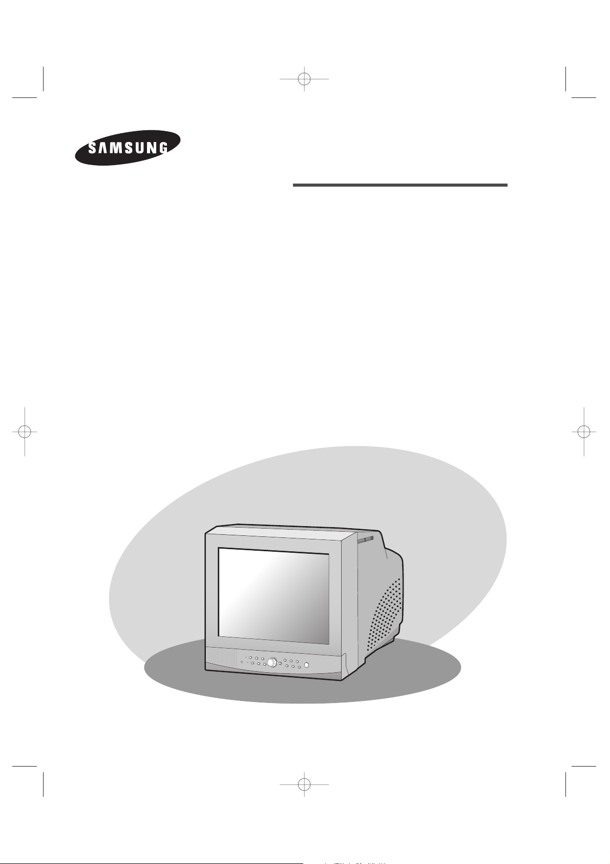
COLOR MONITOR
SMO-210TP
SMO-150TP
User Guide
Mode d’emploi
Bedienungsanleitung
Manuale dell'utente
Guía del usuario
Cover_SMO-210TP 5/30/03 2:57 PM Page 1

Part No.: AA68-02690A-02
Printed in Korea
Cover_SMO-210TP 5/30/03 2:57 PM Page 2
e-2
Graphic Symbol Explanation
The lightning flash with arrowhead symbol, within an
equilateral triangle, is intended to alert the user to the
presence of uninsulated ‘dangerous voltage’ within the
product’s enclosure that may be of sufficient magnitude to
constitute a risk of electric shock to persons.
The exclamation point within an equilateral triangle is
intended to alert the user to the presence of important
operating and maintenance (servicing) instructions in
the literature accompanying the appliance.
Warning - To Prevent Fire or Shock Hazard, Do Not
Expose This Monitor To Rain or Moisture.
CAUTION : TO REDUCE THE RISK OF ELECTRIC SHOCK, DO NOT
REMOVE COVER (OR BACK). NO USER SERVICEABLE
PARTS INSIDE. REFER SERVICING TO QUALIFIED
SERVICE PERSONNEL.
RISK OF ELECTRIC SHOCK
DO NOT OPEN
CAUTION
1_SMO-210TP_ENG 5/30/03 2:56 PM Page e-2

e-3
IMPORTANT SAFEGUARDS
Caution
Power source is indicated on the rear of the set. It contains high-voltage parts.
If you remove the cover, it may cause fire or electric shock. Do not remove the
cover by yourself. (Control switches are at the front of the monitor.)
1. Read Instructions : All the safety and operating instructions should be
read before the appliance is operated.
2. Retain Instructions : The safety and operating instructions should be
retained for future reference.
3. Heed Warnings : All warnings on the monitor and in the operating
instructions should be adhered to.
4. Follow Instructions : All operating and user instructions should be
followed.
5. Cleaning : Unplug this monitor from the wall outlet before cleaning.
Do not use liquid cleaners or aerosol cleaners. Use a damp cloth for
cleaning.
Exception. A monitor that is meant for uninterrupted service and that for
some specific reason, such as the possibility of the loss of an
authorization code for a CATV converter, is not intended to be
unplugged by the user for cleaning or any other purpose, may exclude
the reference to unplugging the monitor in the cleaning description
otherwise required in Item 5.
6. Attachments : Do not use attachments not recommended by Samsung
as they may cause hazards.
7. Water and Moisture : Do not use this monitor near water for example,
near a bathtub, wash bowl, kitchen sink, or laundry tub, in a wet
basement, or near a swimming pool, and the like wet basement, or near a
swimming pool, and the like.
1_SMO-210TP_ENG 5/30/03 2:56 PM Page e-3

e-4
8. Accessories : Do not place this monitor on an unstable cart, stand,
tripod, bracket, or table. The monitor may fall, causing serious injury to
a child or adult, and serious damage to the appliance. Use only with a
cart, stand, tripod. bracket, or table recommended by Samsung, or sold
with the monitor. Any mounting of the monitor should follow
Samsung’s instructions, and should use a mounting accessory
recommended by Samsung.
9. Ventilation : Slots and openings in the cabinet are provided for
ventilation and to ensure reliable operation of the monitor and to protect
it from overheating, and these openings should never be blocked by
placing the monitor on a bed, sofa, rug, or other similar surface. This
monitor should never be placed near or over a radiator or heat register.
This monitor should not be placed in a built-in installation such as a
bookcase or rack unless proper ventilation is provided or Samsung’s
instructions have been adhered to.
10. Power Sources : This monitor should be operated only from the type of
power source indicated on the making label. If you are not sure of the
type of power supply to your installation site, consult your Samsung
dealer or local power company.
11. Grounding or Polarization : For monitors equipped with a 3-wire
grounding-type plug having a third(grounding) pin. This plug will only
fit into a grounding type power outlet. This is a safety feature. If you are
unable to insert the plug into the outlet, contact your electrician to
replace your obsolete outlet. Do not defeat the safety purpose of the
grounding-type plug.
12. Power : Cord Protection-Power supply cords should be routed so that
they are not likely to be walked on or pinched by items placed upon or
against them, paying particular attention to cords at plugs, convenience
receptacles, and the point where they exit from the monitor.
1_SMO-210TP_ENG 5/30/03 2:56 PM Page e-4

e-5
13. Lightning : For added protection for this monitor during a lightning
storm, or when it is left unattended and unused for long periods of time,
unplug it from the wall outlet and disconnect the cable system. This will
prevent damage to the monitor due to lightning and power-line surges.
14. Overloading : Do not overload wall outlets and extension cords as this
can result in a risk of fire of electric shock.
15. Object and liquid Entry : Never push objects of any kind into this
monitor through openings as they may touch dangerous voltage points or
short-out parts that could result in a fire or electric shock.
Never spill liquid of any kind on the monitor.
16. Servicing : Do not attempt to service this monitor yourself as opening or
removing cover may expose you to dangerous voltage or other hazards.
Refer all servicing to qualified service personnel.
17. Damage Requiring Service : Unplug this monitor from the wall outlet
and refer servicing to qualified service personnel under the following
conditions.
a. When the power-supply cord or plug is damaged.
b. If liquid has been spilled, or objects have fallen into the monitor.
c. If the monitor has been exposed to rain or water.
d. If the monitor does not operate normally by following the operating
instructions. Adjust only those controls that are covered by the
operating instructions as an improper adjustment of other controls
may result in damage and require extensive work by a qualified
technician to restore the monitor to its normal operation.
e. If the monitor has been dropped or the cabinet has been damaged.
f. When the monitor exhibits a distinct change in performance-this
indicates a need for service.
1_SMO-210TP_ENG 5/30/03 2:56 PM Page e-5

e-6
18. Replacement Parts : When replacement parts are required, be sure the
service technician has used replacement parts specified by Samsung or
have the same characteristics as the original parts.
Unauthorized substitutions may result in fire, electric shock or other
hazards.
19. Safety Check : Upon completion of any service or repairs to this
monitor, ask the service technician to preform safety checks to
determine that the monitor is in proper operating condition.
FCC & ICES Information
Warning
This equipment has been tested and found to comply the limits for a class A
digital device, pursuant to part 15 of the FCC Rules and ICES-003 of
Industry Canada. These limits are designed to provide reasonable protection
against harmful interference when the equipment is operated in a commercial
environment. This equipment generate, uses, and can radiate radio
frequency energy and, if not installed and used in accordance with the
instruction manual, may cause harmful interference to radio
communications. Operation of this equipment in a residential area is likely to
cause harmful interference in which case the user will be required to correct
the interference at his own expense.
User-Installer Caution
Your authority to operate this FCC verified equipment could be voided if
you make changes or modifications not expressly approved by the party
responsible for compliance to part 15 of the FCC Rules.
1_SMO-210TP_ENG 5/30/03 2:56 PM Page e-6

e-7
Contents
IMPORTANT SAFEGUARDS ..................................................e-3
FCC &ICES Information.............................................................e-6
Chapter 1: Overview ...................................................................e-9
Overview ...........................................................................e-9
Functions and Features......................................................e-9
Names and Functions of Parts .........................................e-10
Chapter 2: Installation ...............................................................e-14
Installation Environments................................................e-14
Unpacking........................................................................e-15
Chapter 3: Connecting to External Devices ..............................e-16
1. Connecting to Time Lapse VCR (or Normal VCR)..e-16
2. Connecting the Alarm Sensor ...................................e-17
3. Connecting the Door Bell Box..................................e-17
4. Connecting the Ordinary monitor .............................e-17
Chapter 4: Basic Operation........................................................e-18
1. Basic Operation.........................................................e-18
2. When you want to watch on LIVE/P.B./TRIPLEX screen
.e-19
3. When you want to watch in Full Screen Mode .........e-19
4. When you want to watch in Multi Screen Mode.......e-19
5. When you want to watch in Sequence Screen Mode.e-20
6. When you want to watch in FREEZE Screen Mode.e-21
7. When you want to watch in Zoom Screen Mode......e-22
8. When you want to watch on PIP Screen Mode.........e-22
9. When you want to watch the VCR output ................e-23
10. When you want to watch the Event Replay screen...e-23
11. When you want to watch a Door Bell screen............e-24
1_SMO-210TP_ENG 5/30/03 2:56 PM Page e-7

e-8
Chapter 5: Setup Menu Settings ...............................................e-25
1. VIEW SETTING ......................................................e-26
2. CLOCK/DISPLAY SET ...........................................e-26
3. CAMERA SETUP ....................................................e-28
4. SYSTEM SETTING .................................................e-35
5. EVENT LIST ............................................................e-40
6. DOOR BELL LIST ...................................................e-40
Chapter 6: Recording.................................................................e-41
1. Recording in Time Lapse (or Normal)Mode.............e-41
2. Alarm/Motion Channel Double-Recording...............e-41
Chapter 7: Alarm,Motion,Loss and Door Bell ..........................e-42
1. Alarm Occurrence .....................................................e-42
2. Motion Occurrence....................................................e-44
3. Loss Occurrence........................................................e-45
4. Door Bell Occurrence................................................e-46
Appendix ...................................................................................e-47
Specifications ..................................................................e-47
Troubleshooting...............................................................e-48
1_SMO-210TP_ENG 5/30/03 2:56 PM Page e-8

e-9
Chapter 1: Overview
Overview
The product is a triplex that enables you to record the signals received from up to 8 cameras
to a single VCR. You can record those signals sequentially by frame or intermittently, and
playback a specific channel selectively. You can use three monitor screen modes, LIVE
Mode, P.B. Mode, and LIVE + P.B. Mode, on a single monitor.
Functions and Features
• Set various functions using the Menu buttons.
• Connect up to 8 cameras for color or black-and-white pictures.
• Watch the input from up to 8 cameras on one screen in the various split display modes.
• Watch the Live screen and the Playback screen simultaneously on the same monitor.
• Enlarge a screen up to 4 Xs using the Zoom function.
• Utilize the Motion Detect function embedded in a camera.
• Monitor a specific screen within the main screen by using the Spot Display function.
• Watch the Main screen simultaneously on an additional monitor using the Slave Display
function.
• Watch desired screens in still mode using the Freeze function.
• Switch and watch channels sequentially in Sequence mode.
• Hide the screens being displayed using the Hidden Camera function.
• The system has Date, Time and Alarm indicators that can be reset .
• When an Alarm occurs, the word "EVENT" is displayed on the screen and a warning
buzzer sounds. When this occurs, you can press Enter (in the center of the Rotary Wheel),
and up to 15 frames before and after the generated alarm will be replayed on the Event
Replay window. Alarm histories are recorded in the EVENT LIST. The Alarm function is
available only when the Alarm Box is connected.
• If the Channel Loss Detection function detects any channel loss, the word "EVENT" is
displayed on the screen and a warning buzzer sounds. When this occurs, you can press
ENTER (in the center of the Rotary Wheel), and up to 15 frames before and after the
detected chancel loss will be replayed on the Event Replay window. Channel Loss
histories are recorded in the EVENT LIST.
• When a doorbell is pressed, a warning buzzer sounds and the screen mode changes to
LIVE, which displays all 9 channels at the same time. The letter "D" is displayed on the
screen of the channel to which the doorbell has been pressed and the still screen is saved
in the Door Bell List. Up to 16 frames can be saved in the Door Bell List. You can select
a frame and view it on the screen. This Door Bell function is available only when the
Door Bell Box is connected.
1_SMO-210TP_ENG 5/30/03 2:56 PM Page e-9
e-10
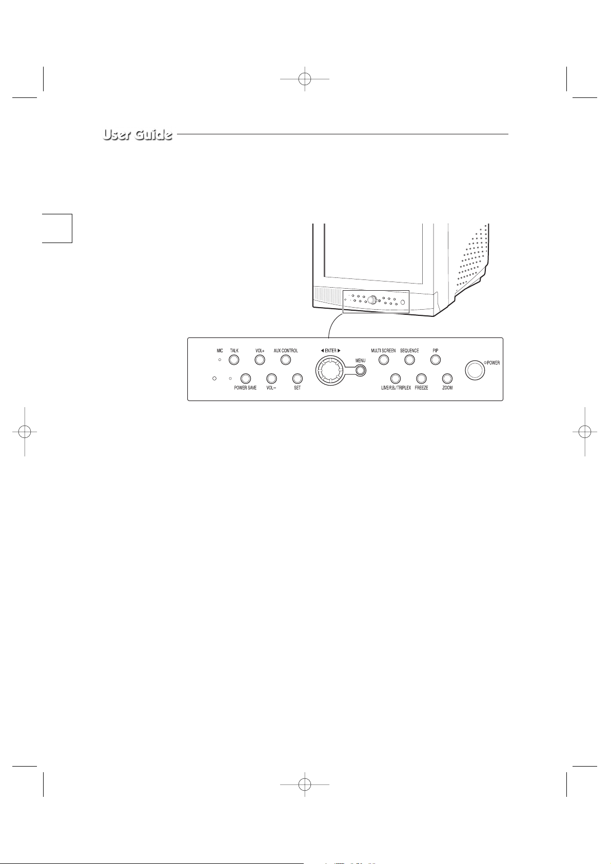
Names and Functions of Parts
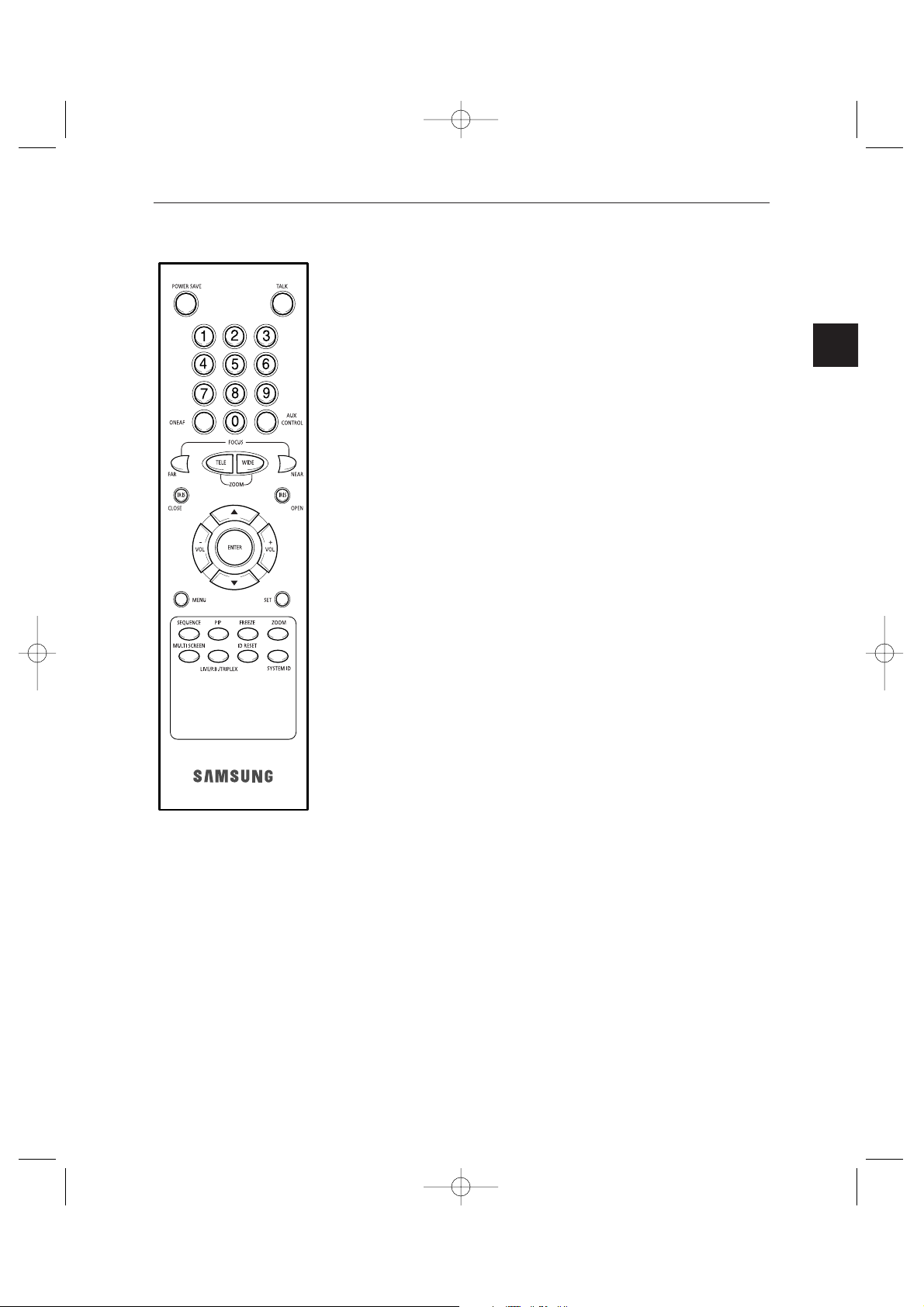
Front Panel/Remote Control
A. POWER SWITCH
Turns the power on/off.
B. POWER SAVE
Changes to Power Save mode.
C. VOLUME +/-
Controls the volume level.
D. TALK
Communicates with the doorbell in duplex mode.
E. AUX CONTROL
Outputs relay pulses to an external device for a specified time.
You can adjust this control according to your environment. (For example, when the
doorbell rings, you can move to the corresponding camera and identify the visitor before
opening the door using the AUX CONTROL button.)
F. LIVE/P.B./TRIPLEX
Changes the Display mode. Each press of this button switches between Live, P.B., and
Triplex modes sequentially.
G. SET
Sets channel options on the split screen, or enters the selected Sub Menu from the Main
Menu.
H. ROTARY WHEEL (LEFT, RIGHT, ENTER)
Press the LEFT button to direct the camera to the left; the RIGHT button, to the right. In
the center is the ENTER button. Use this wheel to move a Zoomed-in screen, or to scroll
through Menu items or channels. Press ENTER to select an item, enter a sub menu, or
replay the events.
1_SMO-210TP_ENG 5/30/03 2:56 PM Page e-10
e-11
I. MENU
Display the Setup menu on the screen. Press it again to exit the Setup
menu.
J. MULTISCREEN
Switches to the split screen view. Each press of this button changes to the
4, 7, and 9-split screen sequentially. Only the 4 and 9 split screens are
available in the Triplex mode.
K. SEQUENCE
When pressed in the full screen mode, channels are switched automatically
and sequentially within a specified time period.
L. FREEZE
Captures the selected screen as a still screen.
Refer to the section "When you want to watch in FREEZE screen mode"
on page 21.
M. PIP
Selects the Picture in Picture mode.
N. ZOOM
When pressed in full screen mode, the screen is enlarged. Each press of this
button enlarges the screen two and four times sequentially and then returns
to the normal size. Use the Rotary Wheel to move the Zoomed-in screen.
O. Number Key(0 ~ 9)
Press the number of the channel to watch it in full screen mode.
Or, press the SYSTEM ID button and then press the number of the system
you want to control with the remote control.
P. ZOOM(TELE/WIDE)
Only the remote control has this button. It is available only when a camera
(SOC-420P, or SOC-920P, sold separately), is connected to the system.
Q. FOCUS(FAR/NEAR)
Only the remote control has this button. It is used for camera Focus control
and available only when a camera (SOC-420P, or SOC-920P, sold
separately), is connected to the system.
R. IRIS(CLOSE/OPEN)
Only the remote control has this button. It is used for camera Iris control
and available only when a camera (SOC-420P, or SOC-920P, sold
separately), is connected to the system.
S. ONEAF
Performs Auto Focus for the selected camera once in the present status.
Only the remote control has this button. It is only available when a camera
(SOC-420P, or SOC-920P, sold separately), is connected with the product.
T. SYSTEM ID
Selects the system to control with the remote. Only the remote control has this
button.
U. ID RESET
Located on the remote control, this button resets the selected System ID to
the default ID (1).
1_SMO-210TP_ENG 5/30/03 2:56 PM Page e-11
e-12
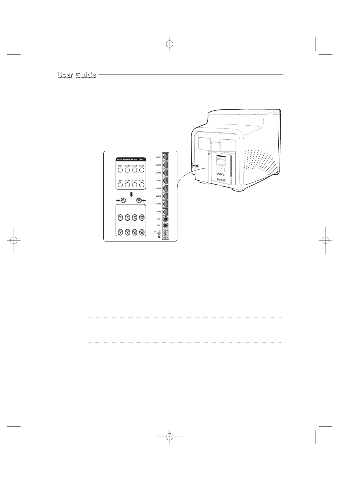
Rear Panel
A. CAMERA IN(RJ-45)
Video camera input terminals. You can connect up to 8 cameras with RJ-45 connectors.
B. CAMERA IN (BNC)
Video camera input terminals. You can connect up to 8 cameras with BNC connectors.
Caution
Either RJ-45 or BNC type cameras should be connected to the same channel. Signal
interference will occur if both types of camera are connected to the same channel.
1_SMO-210TP_ENG 5/30/03 2:56 PM Page e-12

e-13
C. VCR
• Connects to the VCR using a 6-pin connector.
• TRIGGER: Trigger output terminal for the VCR
• VIDEO IN/OUT: Video input/output terminal for the VCR
• AUDIO IN/OUT: Audio input/output terminal for the VCR
D. AUX
• Connects to another device using the 4-pin connector.
• SPOT VIDEO OUT: The terminal that allows you to supervise the specified channel
within the Main screen on the additional connected monitor.
• SPOT AUDIO OUT: The terminal that allows you listen to the sound of the specified
channel on the additional connected monitor.
• SLAVE VIDEO OUT: The terminal that allows you to view the Main screen
displayed at the present time on the additional connected monitor.
E. ALARM
• A/O (HOT/COLD): When an alarm occurs, the Active Make signal is output.
• A/R: Connects to the Alarm Reset terminal of VCR. When an alarm is triggered, a
pulse is output.
• G: Connects to the ground terminal of VCR.
F. ~AC IN
Connects the power cord.
1_SMO-210TP_ENG 5/30/03 2:56 PM Page e-13

e-14
Chapter 2: Installation
Installation Environments
This section describes the environmental requirements for safe installation and use.
Install the product on a flat table or in a rack. It should be used only when level and should not be used
when stood vertically or obliquely. The location in which the main system is installed and the
configuration of the wiring room are very important for proper operation of the system. When the
products are installed too closely together or the location is poorly ventilated, the system may not
operate properly and maintenance of the system may be difficult.
Sufficiently circulate the air within the system operating room and tightly fasten the cover of the main
system to prevent malfunction and reduce system downs due to environmental causes.
There are high voltage parts inside. Do not arbitrarily open the cover.
Install the product in a place that meets the following environmental conditions. Be sure to maintain
the system under the temperatures and humidity conditions given below:
• Operating temperature: 0 °C ~ 40 °C
• Storage temperature: -20 °C ~ 60 °C
• Operating humidity: 20% ~ 85% RH
• Storage humidity: 20% ~ 95 RH
• Input voltage: AC 100 ~ 240V
• Power usage: less than 90 Watts
• Frequency: 50Hz
Caution
When operating the product, the fluctuation of input voltage must be within 10% of the rated voltage
and the external power outlet must be grounded, otherwise, it may cause electric shock or malfunction
of the product. Do not connect heat-generating appliances such as a hair dryer, iron or refrigerator to
the same power outlet in which the product is plugged, otherwise it may cause a fire or malfunction of
the product. The use of an Automatic Voltage Regulator (AVR) is highly recommended to ensure that
stable power is supplied.
Be sure to coil CORE-FERRITE on the connector to reduce electro-magnetic interference (EMI).
1_SMO-210TP_ENG 5/30/03 2:56 PM Page e-14
e-15
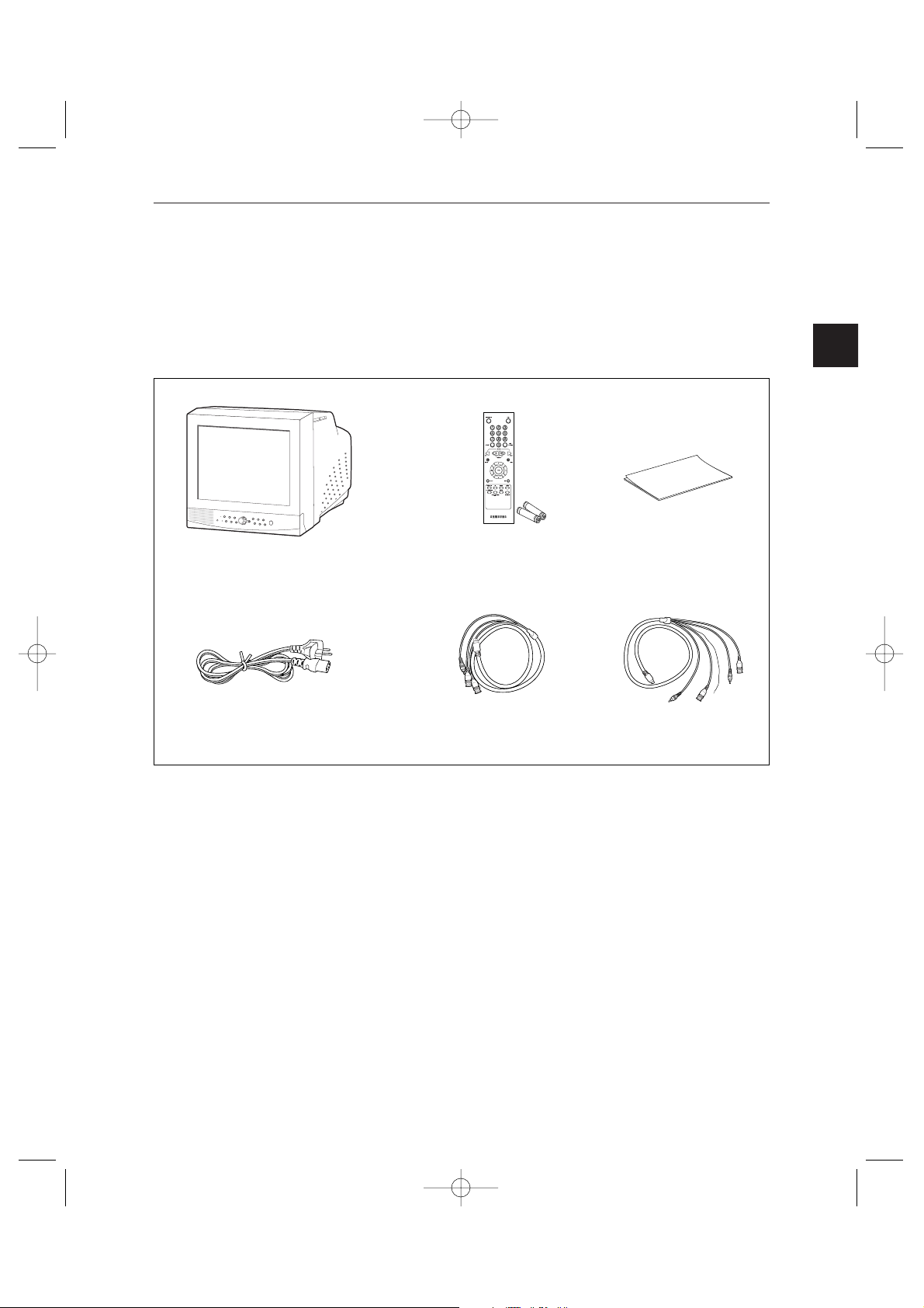
Unpacking
Remove the package cover and place the product on a flat and secure surface or in the
installation location. Check whether all the following devices and accessories are included
with the main system.
Color Monitor Remote Control/
Batteries
User’s Guide
Power Cord 4-Pin Accessory(AUX) 6-Pin Accessory(VCR)
1_SMO-210TP_ENG 5/30/03 2:56 PM Page e-15
e-16
Chapter 3: Connecting to External Devices
The product can be connected to an external device such as a monitor, VCR, Alarm Box,
Door Bell Box, etc.
This chapter describes how to connect to external devices.
Caution
Make sure not to input more than 2V from the camera, video, or audio source, otherwise, it
may cause a malfunction of the product.
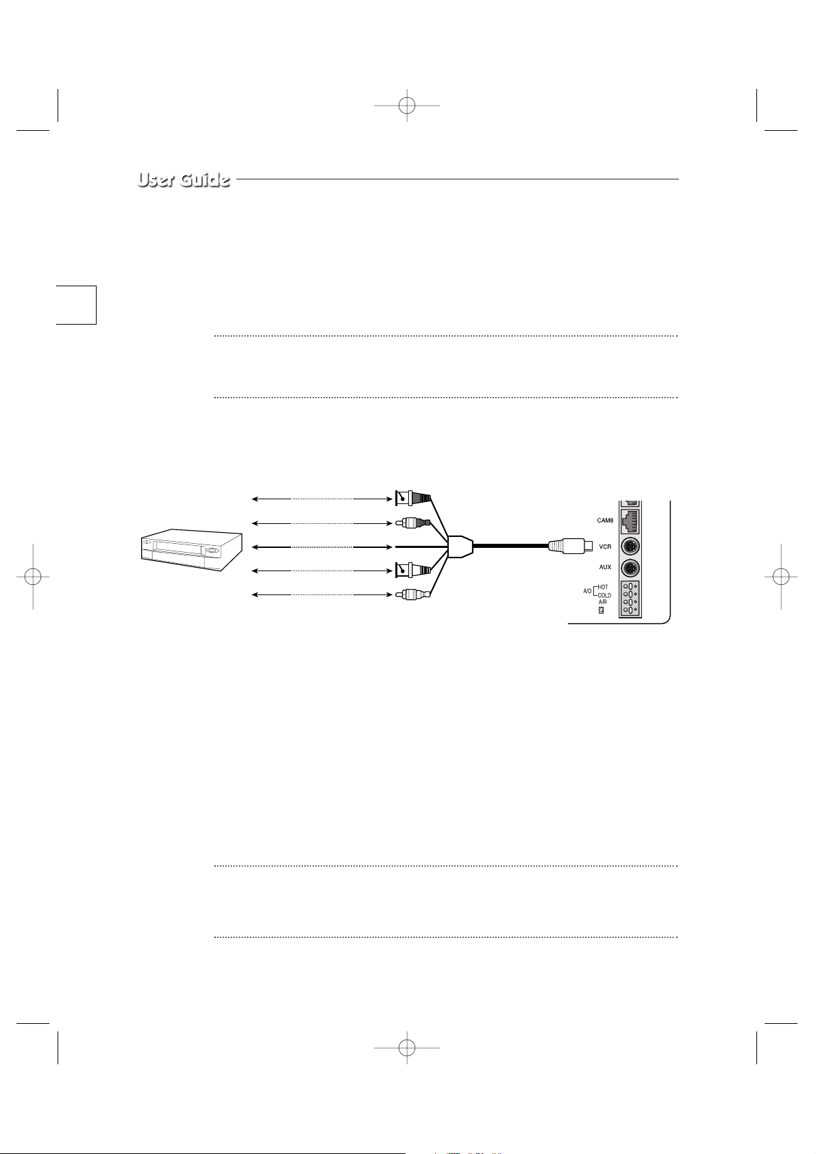
1. Connecting to Time Lapse VCR (or Normal VCR)
1) Connect the 6-pin plug to the VCR terminal on the real panel.
2) Connect the VIDEO OUT plug to the VIDEO IN terminal of the VCR.
3) Connect the VIDEO IN plug to the VIDEO OUT terminal of the VCR.
4) Connect the AUDIO OUT plug to the AUDIO IN terminal of the VCR.
5) Connect the AUDIO IN plug to the AUDIO OUT terminal of the VCR.
6) Connect the TRIGGER plug to the REC TRIGGER OUT terminal of the VCR.
7) Connect the A/O (HOT) terminal on the rear panel to the Alarm IN terminal of the VCR.
8) Connect the A/O (COLD) terminal on the rear panel to the Ground terminal of the VCR.
9) Connect the A/R terminal on the rear panel to the Alarm Reset terminal of the VCR.
10) Connect the G (ground) terminal on the rear panel to the Ground terminal of the VCR.
Caution
The name of the REC TRIGGER OUT or Alarm terminal may change depending on the type
of Time Lapse VCR.
Make sure to check the names of the terminals before connecting them.
VIDEO IN
TIME LAPSE VCR
OR NORMAL VCR
VIDEO OUT
AUDIO IN AUDIO OUT
VIDEO OUT VIDEO IN
AUDIO OUT AUDIO IN
TRIGER OUT TRIGER
1_SMO-210TP_ENG 5/30/03 2:56 PM Page e-16
e-17
2. Connecting the Alarm Sensor
Connect the Alarm Box and Alarm Sensor in accordance with the user manual of Alarm Box.
3. Connecting the Door Bell Box
Connect the cameras and Door Bell Box in accordance with the user manual of Door Bell
Box.
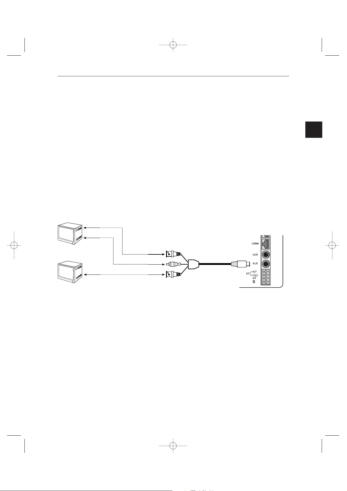
4. Connecting the Ordinary monitor
Connect the ordinary monitor to the Spot output terminal, which allows you to supervise a
specified channel within the Main screen. Connect the Slave Monitor to the output terminal,
which allows you to simultaneously view the current situation .
VIDEO IN
AUDIO IN
SPOT VIDEO OUT
SPOT AUDIO OUT
SLAVE VIDEO OUTVIDEO IN
1_SMO-210TP_ENG 5/30/03 2:56 PM Page e-17

e-18
Chapter 4: Basic Operation
1. Basic Operation
1) Turn the Power Switch On.
When turned on for the first time, the 9-split screens are displayed on the monitor.
At this time, the channels that have no input are displayed with a blue screen and video
loss occurs.
(After completing the initial setup, the settings are memorized when the power is turned
off. Therefore, when you turn the power on again, the product will be operated with the
previous settings.)
2) Select the Display Mode
• Full Screen Mode: When you are on a split screen, move to your desired channel
using the Rotary Wheel and press the ENTER button located at its center. The
selected channel will then be displayed in Full Screen Mode.
• Multi Screen Mode: Press the MULTISCREEN button to display the split screens.
You can select which channels will be displayed on the split screen.
• Sequence Screen Mode: Press the SEQUENCE button. Channels are automatically
switched sequentially in full screen mode.
• Freeze Screen Mode: You can capture and view a still screen using the FREEZE
button and the Rotary Wheel.
• LIVE/P.B. Screen Mode: You can monitor the present camera signals or playback
the recorded screens using the LIVE/P.B./TRIPLEX button.
• TRIPLEX screen Mode: Watch the present camera signals and recorded screens on
the same monitor using the LIVE/P.B./TRIPLEX button.
• PIP screen Mode: You can watch Picture in Picture (PIP) screens by using the PIP
button.
• Zoom screen Mode: You can enlarge a full screen two or four times using the Zoom
button and Rotary Wheel.
1_SMO-210TP_ENG 5/30/03 2:56 PM Page e-18

e-19
2. When you want to watch on LIVE/P.B./TRIPLEX screen.
Select the LIVE, P.B., or TRIPLEX screen mode using the LIVE/P.B./TRIPLEX button.
Each press of this button changes the screen mode to LIVE mode, P.B. mode, and TRIPLEX
mode sequentially.
The LIVE/P.B./TRIPLEX button will not operate in the following cases:
• While using the SETUP Menu
• While displaying the Event List or the Door Bell List
• While replaying events
• While zooming-in the screen
• While setting a split screen
• While setting a still screen on the multi screen mode
3. When you want to watch in Full Screen Mode
If you are on a split screen, move to your desired channel using the Rotary Wheel and press
ENTER. The selected channel will be displayed in full screen mode. At this time, you can
change the channel using the Rotary Wheel.
In addition, you can change the channel by pressing number buttons on your remote control.
4. When you want to watch in Multi Screen Mode
Split screens are available only in LIVE, P.B., and TRIPLEX mode. Press the
MULTISCREEN button to display a split screen. Each press of this button changes the split
screen mode to 4-channel display mode, 7-channel display mode, and 9-channel display
mode sequentially.
Only 4-channel display mode and 9-channel display mode are available in the TRIPLEX
mode. If you press the MULTISCREEN button in full screen mode, the previous split screen
is displayed.
1_SMO-210TP_ENG 5/30/03 2:56 PM Page e-19

e-20
Resetting Channels
1) Press the SET button. The border of the selected channel will blink.
2) Press the ENTER button at the center of the Rotary Wheel. Now, you can change to your
desired channel.
3) Move to your desired channel using the Rotary Wheel and press ENTER to complete
changing the channel.
4) If you want to reset to another channel, use the Rotary Wheel to move to the channel you
want to change and the border of the selected channel will blink.
5) Repeat steps 2) and 3). When the resetting is completed, press the SET button.
✽ With the input of the 8 Video signals, Channel Resetting does not occur in the 9-split
screen mode.
The MULTISCREEN button will not operate in the following cases:
• While using the SETUP Menu
• While displaying the Event List or Door Bell List
• While replaying events
• While zooming-in the screen
• While setting a split screen
5. When you want to watch in Sequence Screen Mode
The Sequence screen is available only in full-screen LIVE mode. Press the SEQUENCE
button when the screen is in full-screen LIVE mode to switch to the Sequence screen. You
can set the switching intervals by going to "SEQUENCE" under "4. SYSTEM SETTING" on
the SETUP MENU. The range of switching intervals is from one to thirty seconds. Press the
SEQUENCE button again to stop the screen displayed at the present time.
The SEQUENCE button will not operate in the following cases:
• While operating in P.B. or TRIPLEX mode
• While using the SETUP Menu
• While setting or displaying a split screen
• While displaying the Event List or Door Bell List
• While replaying events
• While zooming-in the screen
1_SMO-210TP_ENG 5/30/03 2:56 PM Page e-20

e-21
6. When you want to watch in FREEZE Screen Mode
You can stop a full or split screen temporarily and view the still screen in LIVE, P.B.,
TRIPLEX mode.
You can select and stop the channels you wish to stop in split screen mode.
1) In Full Screen Mode
Press the FREEZE button. The present screen being displayed is stopped and the
"FREEZE" message is displayed. Press the button again to exit the still screen.
2) In Split Screen Mode
! Press the FREEZE button. The border of the selected channel will blink.
@ Press ENTER. The screen of the selected channel is stopped and the letter "F" is
displayed. Press ENTER again to exit the still screen.
# If you want to watch another channel in still screen mode, move to the desired
channel using the Rotary Wheel and press ENTER. The screen of the selected
channel is stopped and the letter "F" is displayed. Press ENTER again to exit the still
screen.
$ If you want to watch another channel in still screen mode, repeat Step 3).
% Press the FREEZE button again to exit FREEZE mode.
The FREEZE button will not operate in the following cases:
• While using the SETUP Menu
• While displaying the Event List or Door Bell List
• While replaying events
• While setting a split screen
1_SMO-210TP_ENG 5/30/03 2:56 PM Page e-21

e-22
7. When you want to watch in Zoom Screen Mode
Zooming a screen is available in both LIVE/P.B and Full Screen modes.
1) Press the Zoom button. The current screen enlarges two times.
2) Press the button again. The screen enlarges four times.
3) Press the button once more. The screen returns to normal .
4) You can move to the desired place on the present Zoom screen by using the Rotary
Wheel.
5) Press ENTER on the Rotary Wheel and turn the Rotary Wheel. By using the left, right,
up and down buttons, the enlarged Zoom screen is moved to the right, left, up, or down.
The ZOOM button will not operate in the following cases:
• While setting or displaying a split screen
• While using the SETUP Menu
• While displaying the Event List or Door Bell List
• While replaying events
• While operating in Sequence mode
8. When you want to watch on PIP Screen Mode
You can watch a Picture in Picture screen in full-screen LIVE mode using the PIP button.
When you press the PIP button for the first time, the sub screen on the PIP screen is a
sequence screen. After that, when you enter into PIP mode again, the sub screen which is
displayed in the same screen mode as when you exited the PIP mode previously.
Using PIP Screen
1) Press the PIP button in full-screen LIVE mode.
2) When a fixed channel is displayed on the sub screen, each time you press ENTER it
switches between the Main screen and the Sub screen.
3) Turn the Rotary Wheel to change the channel of the Main screen.
4) Press the SEQUENCE button to set the Sub screen as the sequence screen. Press the
button again to fix the channel.
5) You can change the position of the sub screen by going to "PIP POSITION" under
"2.CLOCK/DISPLAY SET" on the SETUP menu.
1_SMO-210TP_ENG 5/30/03 2:56 PM Page e-22

e-23
The PIP button will not operate in the following cases:
• While operating in P.B. or TRIPLEX mode
• While setting or displaying a split screen
• While using the SETUP Menu
• While displaying the Event List or Door Bell List
• While replaying events
• While zooming-in the screen
• While operating in Sequence mode
• In case of no Video input signal
• When the input signal channel is in the Full-screen mode at the time of Single video input
9. When you want to watch the VCR output
To watch the VCR output directly, set the PB THROUGH item to "ON" by going to
"RECORD..." under "4. SYSTEM SETTING" on the SETUP menu while in P.B. mode. This
function is useful when setting the menu of VCR or when checking whether the VCR is
normal or not. Press ENTER again to exit the PB THROUGH screen and return to the
previous PB screen.
The PB THROUGH button will not operate in the following case:
• While operating in LIVE or TRIPLEX mode
10. When you want to watch the Event Replay screen
1) When an Alarm/Motion signal is input
You can use the alarm function only when an Alarm Box is connected.
When an alarm/motion signal is input, the word "EVENT" is displayed on the screen, and
a warning buzzer sounds. When this occurs, if you press ENTER, up to 15 frames before
and after the generated alarm/motion signal are replayed on the Event Replay window.
Press ENTER again to stop the event replay. If alarm/motion signals are input on more
than one channel, press ENTER to start the event replay for another channel when the
current event replay finishes. When an event replay for all the channels on which an
alarm/motion signal has occurred has finished, press ENTER to exit Event Replay mode.
Alarm/Motion histories are recorded in the EVENT LIST.
1_SMO-210TP_ENG 5/30/03 2:56 PM Page e-23

e-24
2) When Channel Loss is detected
If the channel loss detection function detects a channel loss, the word "EVENT" is
displayed on the screen and a warning buzzer sounds. When this occurs, press ENTER
and up to 15 frames before and after the detected channel loss are replayed on the Event
Replay window.
Press ENTER again to stop the event replay. If channel loss is detected on more than one
channel, press ENTER to start event replay for the next channel when the current event
replay finishes. When the event replay for all the channels on which channel loss has
been detected finishes, press ENTER to exit the Event Replay mode.
Channel loss histories are recorded in the EVENT LIST.
11. When you want to watch a Door Bell screen
You can use the Door Bell screen only when a Door Bell Box is connected.
If the doorbell is pressed, a warning sound is generated and the screen mode changes to LIVE
mode, which displays 9 channels at the same time. The letter "D" is displayed on the screen
of the channel on which the doorbell has been pressed and a still screen is saved in the Door
Bell List. Up to 16 frames can be saved in the Door Bell List. You can select a frame and
view it on the screen.
Move to your desired item by going to "6. DOOR BELL LIST" on the SETUP menu and
press ENTER to display it as a still screen.
Then, press ENTER again to return to the "DOOR BELL LIST" screen.
1_SMO-210TP_ENG 5/30/03 2:56 PM Page e-24
e-25
Chapter 5: Setup Menu Settings
<SETUP MENU>
• Press the MENU button to display the Language Selection screen.
• Select the desired language by using the Rotary Wheel and press ENTER to display the
SETUP MENU in the desired language.
• When you press the MENU button after completing the initial language selection, the
Language Select screen will not appear. Instead the following SETUP MENU will appear
on the monitor. Press the button once again to return to the previous menu.
<SUB MENU >
• Select submenu 1 to 6 from the SETUP MENU using the Rotary Wheel and press
ENTER to go to the SUB MENU.
ENGLISH
ESPAÑOL
FRANÇAIS
ITALIANO
DEUTSCH
[SETUP MENU]
1. VIEW SETTING
2. CLOCK/DISPLAY SET
3. CAMERA SETUP
4. SYSTEM SETTING
5. EVENT LIST
6. DOOR BELL LIST
1_SMO-210TP_ENG 5/30/03 2:56 PM Page e-25
e-26
1. VIEW SETTING
You can change the contrast, brightness, color and sharpness of the Main screen on the
monitor. Select “1. VIEW SETTING” from the SETUP MENU using the Rotary Wheel and
press ENTER to display the following screen:
• Select an item using the Rotary Wheel and press ENTER to change the preset value.
• Change the preset value (0 ~ 100) by using the Rotary Wheel and press ENTER to save
the setting.
• Select SAVE (save the changes), QUIT (exit the setting mode without saving) or
PRESET (reset all the settings to the factory defaults) from the EXIT MENU and press
ENTER to return to the SETUP MENU.
2. CLOCK/DISPLAY SET
You can change PIP position, display type, date type and time.
Select “2. CLOCK/DISPLAY SET” from the SETUP MENU using the Rotary Wheel and
press ENTER to display the following screen:
• Select an item using the Rotary Wheel and press ENTER to change the preset value.
• Change the preset value using the Rotary Wheel and press ENTER to save the setting.
• Press the MENU button to return to the SETUP MENU.
[VIEW SETTING]
CONTRAST 50
BRIGHT 50
COLOR 50
SHARPNESS 50
EXIT QUIT
[CLOCK/DISPLAY SET]
PIP POSITION BOTTOM RIGHT
DISPLAY TYPE ALL
BORDER COLOR WHITE
DATE TYPE YY/MM/DD
DATE[YY/MM/DD] 02/08/01
TIME [HH:MM:SS] 12:30:01
1_SMO-210TP_ENG 5/30/03 2:56 PM Page e-26

e-27
PIP POSITION: BOTTOM-RIGHT ↔ TOP-LEFT ↔ TOP-RIGHT ↔ BOTTOM-LEFT.
• Select the PIP position among the four options listed above.
DISPLAY TYPE: ALL ↔ TITLE ↔ DATE/TIME ↔ NONE.
• ALL: All items will be displayed except the DATE/TIME and the TITLE.
• TITLE: Only the CHANNEL TITLE will be displayed.
• DATE/TIME: Only the DATE/TIME will be displayed.
• NONE: Neither the DATE/TIME nor the TITLE will be displayed.
BORDER COLOR: WHITE ↔ BLACK
• WHITE : BORDER LINE COLOR is displayed in WHITE in Multi Screen mode.
• BLACK : BORDER LINE COLOR is displayed in BLACK in Multi Screen mode.
DATE TYPE: YY/MM/DD ↔ MM/DD/YY ↔ DD/MM/YY.
DATE [YY/MM/DD]
• Year(YY) : 00(2000) ~ 99(2099)
• Month(MM) : 01 ~ 12
• Day(DD) : 01 ~ 31
TIME [HH:MM:SS]
• Hour(HH) : 00 ~ 23
• Minute(MM) : 00 ~ 59
• Second(SS) : 00 ~ 59
1_SMO-210TP_ENG 5/30/03 2:56 PM Page e-27
e-28
3. CAMERA SETUP
You can change the Camera ID, LOSS DETECT, MOTION DETECT and Camera Preset
values.
Select “3. CAMERA SETUP ”from the MAIN MENU using the Rotary Wheel and press
ENTER to display the following screen.
Select the desired channel using the Rotary Wheel and press ENTER to go to the display of
the selected channel. The following screen will appear.
• All the items, except “CAMERA ID ”and “LOSS DETECT,” will be available for setting
only after the system is connected to a camera (SOC-420P or SOC-920P, sold
separately).
• Select the desired item using the Rotary Wheel and press ENTER. Then change the
preset value using the Rotary Wheel and press ENTER to complete the setting.
• Select SAVE (save the changes), QUIT (exit the setting mode without saving) or
PRESET (reset all the settings to the factory defaults) from the EXIT menu and press
ENTER to return to the previous CAMERA SETUP menu.
You can’t return to the previous menu while in the setting mode. You can only return to
the previous menu by selecting EXIT.
• Change the preset values for the other channels repeating the same steps.
• Press the MENU button after completing all the settings to return to the SETUP MENU.
[CAMERA SETUP]
SETUP CAMERA 1...
SETUP CAMERA 2...
SETUP CAMERA 3...
SETUP CAMERA 4...
SETUP CAMERA 5...
SETUP CAMERA 6...
SETUP CAMERA 7...
SETUP CAMERA 8...
[SETUP CAMERA 1]
CAMERA ID ---CH1---LOSS DETECT ON
IRIS ALC...
SHUTTER OFF
WHITE BALANCE ATW
SPECIAL...
FOCUS ONEAF
MOTION DETECT...
EXIT SAVE
1_SMO-210TP_ENG 5/30/03 2:56 PM Page e-28
e-29
CAMERA ID: ---CH1----(“- ” indicates blank.)
• Select “CAMERA ID” using the Rotary Wheel and press ENTER to select the first “- .”
• Select the desired letter using the Rotary Wheel and press ENTER to move on and
select the next letter.
(Letter order: 0123456789ABCDEFGHIJKLMNOPQRSTUVWXYZ-[ ]x+/.)
• Repeat the same to select all the desired letters. (You can choose up to ten letters.)
LOSS DETECT: Sets the Loss Detect On/Off. (ON ↔ OFF)
IRIS: Controls the video output level through the Iris depending on the level of light
coming into the camera.
• Select “IRIS” using the Rotary Wheel and press ENTER to select either “ALC...” or
“MANUAL…”.
• ALC... : Auto Light Compensation
- Select “ALC...” using the Rotary Wheel and press the SET button to display the
following screen. Press the MENU button after completing the setting to return to the
previous menu.
- Select AREA using the Rotary Wheel and press ENTER to select either
“PRESET...” or “USER…”.
- Select “PRESET...” using the Rotary Wheel and press the SET button to display the
following screen. The back light compensation will be applied to the area(s) with
preset values.
Press the MENU button to return to the previous menu.
[ALC]
AREA PRESET...
BLC OFF
LEVEL[ 00 ] ----------+----------
[RESET AREA]
1_SMO-210TP_ENG 5/30/03 2:56 PM Page e-29
 Loading...