

Samsung SMH9151S, SMH9151BE, SMH9151BE/XAA, SMH9151STE Service Manual
BASIC: SMH9151S
MODEL: SMH9151BE
MODEL CODE: SMH9151BE/XAA
1. Precaution
2. ProductSpecication
3. Disassembly and Reassembly
4. Troubleshooting
5. Exploded Views and Part List
6. PCB Diagrams
7. Wiring Diagrams
8. Schematic Diagrams

•Contents
1. Precaution ..............................................................................3
1-1 Safety precautions .....................................................................4
1-2 Special High Voltage Precautions .........................................................5
2.Specications ...........................................................................6
2-1 Features .............................................................................6
2-2 Accessory ............................................................................6
2-3 Table of Specications ..................................................................7
3. Disassembly and Reassembly ..............................................................8
3-1 Replacement of High Voltage Transformer ..................................................8
3-2 Replacement of Magnetron .............................................................10
3-3 Replacement of Door Assembly ..........................................................11
3-4 Replacement of Fuse ..................................................................13
3-5 Replacement of Drive Motor ............................................................13
3-6 Removal of stirrer .....................................................................14
3-7 Replacement of Control Circuit Board .....................................................15
3-8 Replacement of Cooktop lamp ...........................................................16
3-9 Replacement of Oven Light .............................................................17
4. Troubleshooting ........................................................................18
4-1 Parts checking method .................................................................18
4-2 Error Code Numbering Rule .............................................................19
4-3 Error Code List .......................................................................19
4-4 Electrical Malfunction ..................................................................21
5. Exploded Views and Parts List ............................................................38
5-1 Exploded Views ......................................................................38
5-2 Main Parts List .......................................................................39
5-3 Door Parts List .......................................................................41
5-4 Control Parts List .....................................................................42
5-5 Standard Parts List ....................................................................43
6. PCB Diagrams ..........................................................................44
6-1 PCB Diagrams .......................................................................44
6-2 PCB Diagrams .......................................................................45
7. Wiring Diagrams ........................................................................46
7-1 Wiring Diagrams ......................................................................46
8. Schematic Diagrams .....................................................................48
8-1 Schematic Diagram ...................................................................48
2
1. Precaution
3
1. Precaution
Follow these special safety precautions. Although the microwave oven is completely safe during ordinary use,
repair work can be extremely hazardous due to possible exposure to microwave radiation, as well as potentially
lethal high voltages and currents.
1-1 Safety precautions ( )
1. All repairs should be done in accordance with the
procedures described in this manual. This product
complies with Federal Performance Standard 21
CFR
2. Microwave emission check should be performed to
prior to servicing if the oven is operative.
3. If the oven operates with the door open :Instruct
the user not to operate the oven and contact
the manufacturer and the center for devices and
radiological health immediately.
4. Notify the Central Service Center if the microwave
leakage exceeds 5 mW/cm2.
5. Check all grounds.
6. Do not power the MWO from a “2-prong” AC cord.
Be sure that all of the built-in protective devices are
replaced. Restore any missing protective shields.
7. When reinstalling the chassis and its assemblies,
be sure to restore all protective devices, including:
nonmetallic control knobs and compartment covers.
8. Make sure that there are no cabinet openings
through which people --particularly children--might
insert objects and contact dangerous voltages.
Examples: Lamp hole,ventilation slots.
9. Inform the manufacturer of any oven foundto have
emission in excess of 5 mW/cm2 ,Make repairs to
bring the unit into compliance at no cost to owner
and try to determine cause. Instruct owner not to use
oven until it has been brought into compliance.
CENTRAL SERVICE CENTER
10. Service technicians should remove their watches
while repairing an MWO.
11. To avoid any possible radiation hazard,replace parts
in accordance with the wiring diagram. Also, use
only the exact replacements for the following parts:
Primary and secondary interlock switches, interlock
monitor switch.
12. If the fuse is blown by the Interlock Monitor Switch:
Replace all of the following at the same time:
Primary, door sensing switch and power relay, as
well as the Interlock Monitor Switch. The correct
adjustment of these switches is described elsewhere
in this manual. Make sure that the fuse has the
correct rating for the particular model being repaired.
13. Design Alteration Warning: Use exact replacement
parts only, i.e.,only those that are specied in
thedrawings and parts lists of this manual. This
is especially important for the Interlock switches,
described above. Never alter or add to the
mechanical or electrical design of the MWO.
Any design changes or additions will void the
manufacturer’s warranty. Always unplug the unit’s
AC power cord from the AC power source before
attempting to remove or reinstall any component or
assembly.
14. Never defeat any of the B+ voltage interlocks. Do not
apply AC power to the unit (or any of its assemblies)
unless all solid-state heat sinks are correctly
installed.
15. Some semiconductor (“solid state”) devices
are easily damaged by static electricity. Such
components are called Electrostatically Sensitive
Devices (ESDs). Examples include integrated
circuits and eld-effect transistors. Immediately
before handling any semiconductor components or
assemblies, drain the electrostatic charge from your
body by touching a known earth ground.
16. Always connect a test instrument’s ground lead to
the instrument chassis ground before connecting the
positive lead; always remove the instrument’s ground
lead last.
17. When checking the continuity of the witches or
transformer, always make sure that the power is
OFF, and one of the lead wires is disconnected.
18. Components that are critical for safety are indicated
in the circuit diagram by shading, or .
19. Use replacement components that have the same
ratings, especially for ame resistance and dielectric
strength specications. A replacement part that does
not have the same safety characteristics as the
original might create shock, re or other hazards.
NOTE : Connect the oven to a 20A. When
connecting the oven to a 15A,make sure that circuit
breaker can operate.
4
1. Precaution
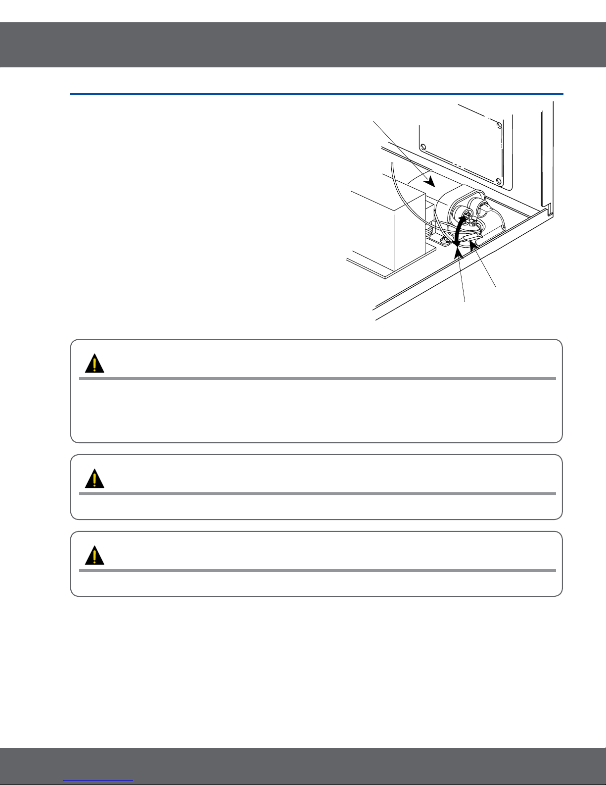
H. V. Diode
Short
H. V. Capacitor
1-2 Special High Voltage Precautions
1. High Voltage Warning Do not attempt to measure any of
the high voltages --this includes the lament voltage of the
magnetron. High voltage is present during any cook cycle.
Before touching any components or wiring, always unplug
the oven and discharge the high voltage capacitor (See
Figure 1-1)
2. The high-voltage capacitor remains charged about 30
seconds after disconnection. Short the negative terminal
of the high-voltage capacitor to to the oven chassis. (Use a
screwdriver.)
3. High voltage is maintained within specied limits by close-
tolerance, safety-related components and adjustments. If
the high voltage exceeds the specied limits, check each
of the special components.
PRECAUTION
There exists HIGH VOLTAGE ELECTRICITY with high current capabilities in the circuits of the HIGH
VOLTAGE TRANSFORMER secondary and lament terminals. It is extremely dangerous to work on or
near these circuits with the oven energized.
DO NOT measure the voltage in the high voltage circuit including lament voltage of magnetron.
PRECAUTION
Servicemen should remove their watches whenever working close to or replacing the magnetron.
PRECAUTION
Never touch any circuit wiring with your hand nor with uninsulated tool during operation.
5
2.Specications
2-1 Features
Product Features
•StirrerandTurntable Continually rotates food to ensure even cooking.
•InstantCook Instant On Controls - Allow quick, one touch cooking and reheating.
•VentingSystem
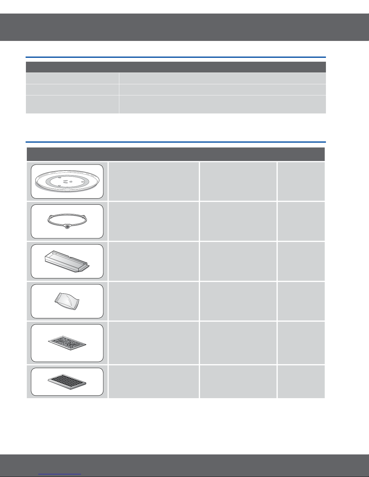
2-2 Accessory
Item Description Code No. Q’ty
Two speed, 300CFM venting system - Quickly removes smokr and
steam from cook top
TRAY-COOKING DE63-00536A 1
ASSY-GUIDE ROLLER DE92-90495C 1
ASSY-HOOD DAMPER DE92-90242D 1
ASSY-HARD WARE DE92-90505G 1
FILTER-AIR DE63-00196A 1
FILTER-CHARCOAL DE63-00367E 1
6

2.Specications
2-3TableofSpecications
Items
Cavity Size (cu.ft.) 1.6 1.6
Power
Power Source 120 V / 60 Hz 120 V / 60 Hz
Output Power (Watts) 1000 1000
Power Consumption (Watts/Amp) 1580/13.5 1580/13.5
Characteristics
Control Method Touch Touch
Display LED LED
Sensor No No
Cooking Timer 99 min. 99 sec. 99 min. 99 sec.
Power Level 10 10
Auto Defrost Yes Yes
Auto Reheat Yes Yes
One Touch Instant Cook Pads Yes Yes
Soften/Melt Yes Yes
More/Less Yes Yes
Cooking Stages 2 2
Add 30 sec No No
One Minute Yes Yes
Clock Yes Yes
Kitchen Timer Yes Yes
Weight Option Oz Oz
Reminder End Signal On/Off No No
Child Safety Lock Yes Yes
Clock System Option (12 hrs / 24 hrs) 12 hrs 12 hrs
Demonstration Mode No No
Numeric Pads 0-9 0-9
Turntable Distribution Stirrer + Turntable Stirrer + Turntable
Turntable On/Off No No
End Signal Sound Yes Yes
Vent Fan CFM 220 220
Vent Orientation Vertical Vertical
Vent Fan Control Hi/Lo/Off Hi/Lo/Off
Cooktop Lighting Hi/Lo/Off Hi/Lo/Off
Cabinet Colour STSS/Black/White/Silver STSS/Black/White/Silver
Cavity Interior Epoxy Epoxy
Cabinet Dimensions W x H x D (inches) 29 7/8 x 16 1/2 x 15 1/16 29 7/8 x 16 1/2 x 15 1/16
Net Weight (lb)
Shipping Properties
Shipping Dimensions W x H x D (inches) 33 3/8 x 19 15/16 x 19 13/32 33 3/8 x 19 15/16 x 19 13/32
Loading Q’ty (sets / 40ft) 330 (Jumbo) 330 (Jumbo)
Shipping Weight (lb)
STSS: 45.9 lbs / Plastic: 44.5
STSS: 53.4 lbs / Plastic: 52.0
Basic Model New Model
SMH9151S SMH9151BE
lbs
lbs
STSS: 45.9 lbs / Plastic: 44.5 lbs
STSS: 53.4 lbs / Plastic: 52.0 lbs
7
3. Disassembly and Reassembly
MAGNETRON, MOTOR ASSEMBLY, VENT BLOWER AND HIGH VOLTAGE TRANSFORMER
Oven must be removed from wall.
REMOVING OVEN FROM WALL (2 PEOPLE REQUIRED)
Oven is hooked on metal tabs at bottom of wall mounting plate and to cabinet by (3) top cabinet bolts.
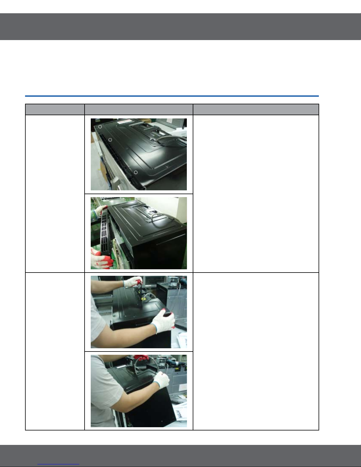
3-1 Replacement of High Voltage Transformer
Parts Explaination Photo Explaination
1. Disconnect oven power.
Grille
Panel Outer
2. Remove Grille.
1) Remove 2 screws
2) Slide the Grille to the left, then pull it
straght out.
3. Remove Panel Outer.
8

3. Disassembly and Reassembly
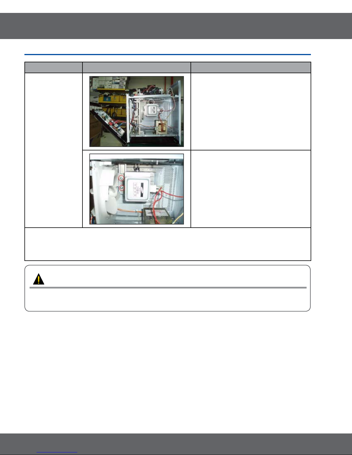
3-1 Replacement of High Voltage Transformer
Parts Explaination Photo Explaination
4. Discharge the High voltage capacitor.
High
voltage
capacitor
5. Disconnect all the leads.
Base
Bottom
HV Trans
6. Remove Base
bottom.
7. Take out the HV Trans.
9
3. Disassembly and Reassembly
3-2 Replacement of Magnetron
Parts Explaination Photo Explaination
Magnetron
Remove the magnetron including the shield
case, permanent magnet, choke coils and
capacitors (all of which are contained in one
assembly).
1. Disconnect all lead wires from the
magnetron.
2. Remove nuts (4) securing the magnetron
to the wave guide.
3. Take out the magnetron very carefully.
NOTE1: When removing the magnetron, make sure that it antenna does not hit any adjacentparts, or it may be
damaged.
NOTE2: When replacing the magnetron, be sure to remount the magnetron gasket in the correct position and make
sure the gasket is in good condition.
PRECAUTION
During replacement, be certain R.F. anode gasket is in place around anode stub.
PERFORM MICROWAVE LEAKAGE TEST
10
3. Disassembly and Reassembly
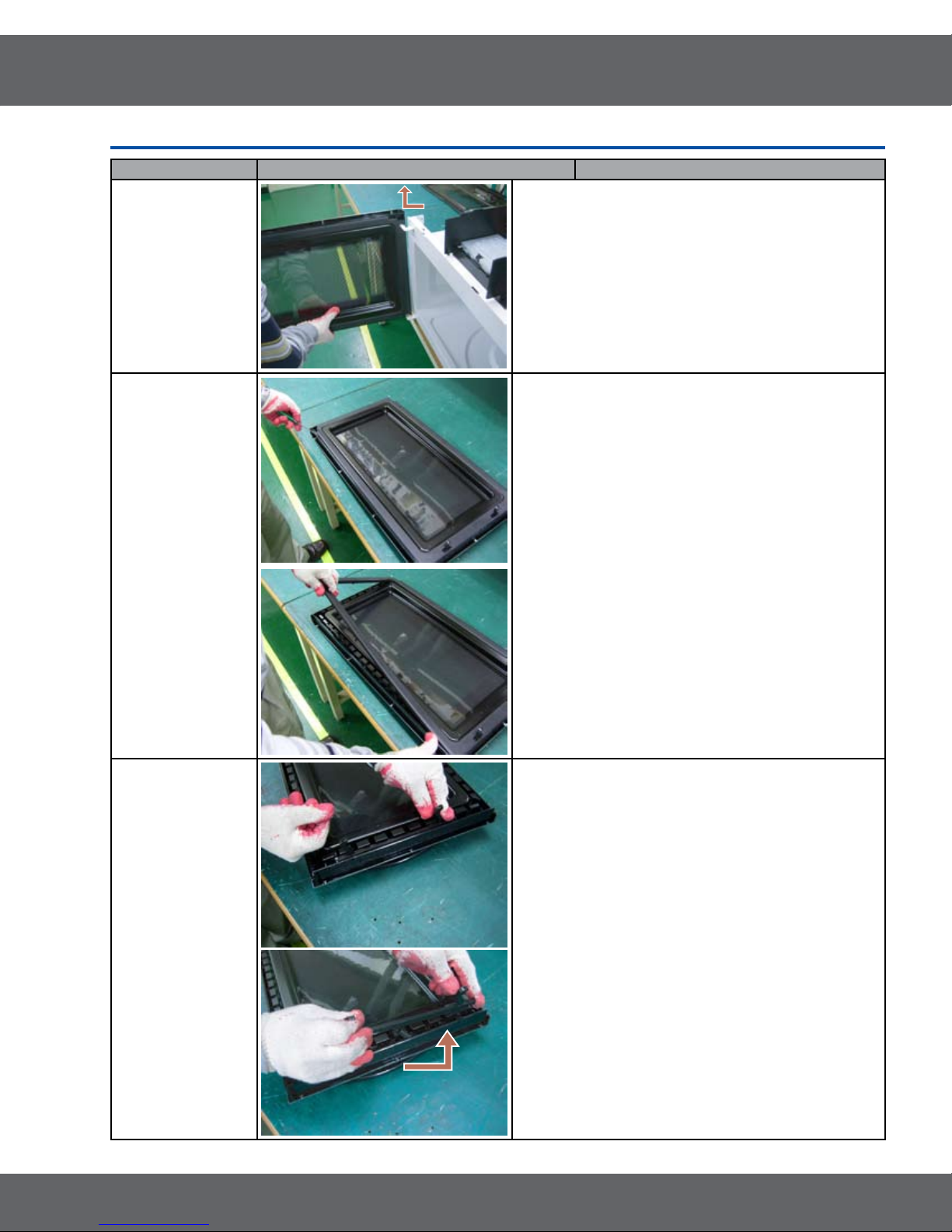
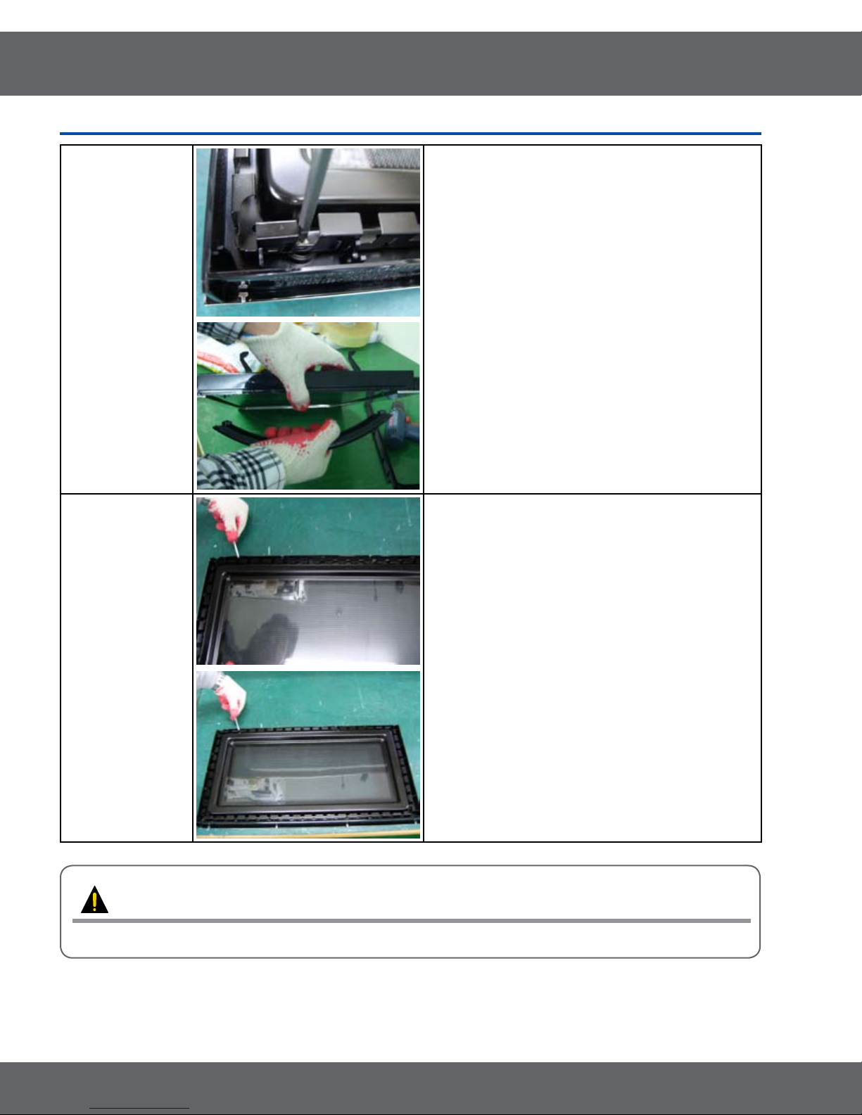
3-3 Replacement of Door Assembly
Parts Disassembly Photo Explaination
Removal of
Door Assembly
1. Insert at screwdriver into the gap between Door
“A” and Door “C” to remove Door “C”. Be careful
when handling Door “C” because it is fragile.Then
remove the door assembly.
Removal of
Door C
Removal of Key
Door & Spring
2. Insert at screwdriver into the gap between Door
“A” and Door “C” to remove Door “C”.
•Becareful when handling Door “C” because it is
fragile.
3. Detach the spring and key door from Door.
11
3. Disassembly and Reassembly
3-3 Replacement of Door Assembly
Removal of
Handle
Removal of
Door “E”
4. Remove 2 screws, then handle is detached from
Door “A”.
5. Following the procedure as shown in the gure,
insert and bend a thin metal plate between Door
“E” and Door “A” until you hear the ‘tick’ sound.
•Insertion depth of the thin metal plate should be
0.5mm or less.
PRECAUTION
PERFORM MICROWAVE LEAKAGE TEST
12
3. Disassembly and Reassembly
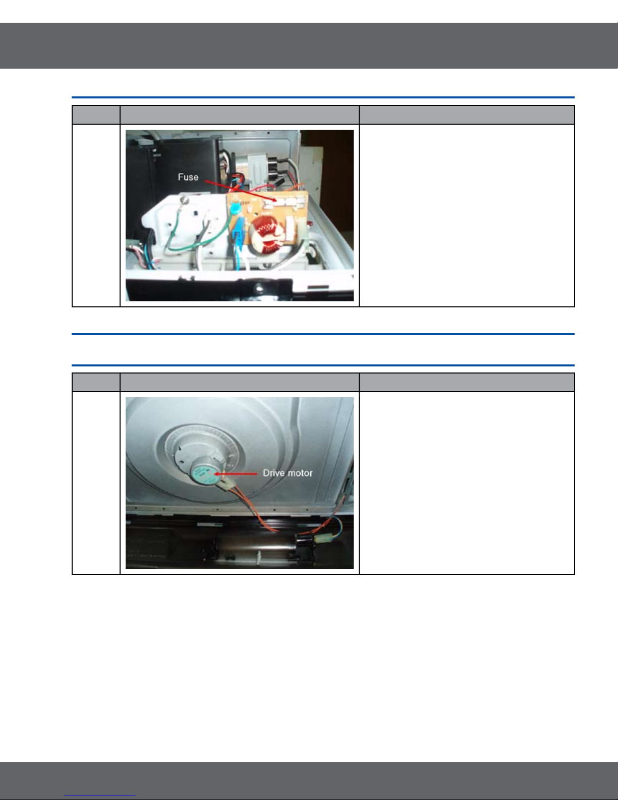
3-4 Replacement of Fuse
Parts Explaination Photo Explaination
The fuse is located on the noise lter.
1. Disconnect power and remove grille.
2. Replace the fuse.
3. When 20A fuse blows out by the operation
of interlock monitor switch failure, replace
Fuse
the primary interlock switch, secondary
interlock switch, door sensing switch,
interlock monitor switch and power relay.
4. When the above four switches operate
properly, check if any other part such as the
control circuit board, blower motor or high
voltage transformer is defective.
3-5 Replacement of Drive Motor
Parts Explaination Photo Explaination
1. Disconnect power and remove bottom plate
screws(5).
2. Remove bottom plate and disconnect the
turntable motor drive.
Drive
Motor
3. Remove turntable motor screws(1) and pull
the turntable motor out.
4. When replacing the drive motor, be sure to
remount it in the correct position with the
coupler.
5. Connect all the leads to the drive motor.
13
3. Disassembly and Reassembly
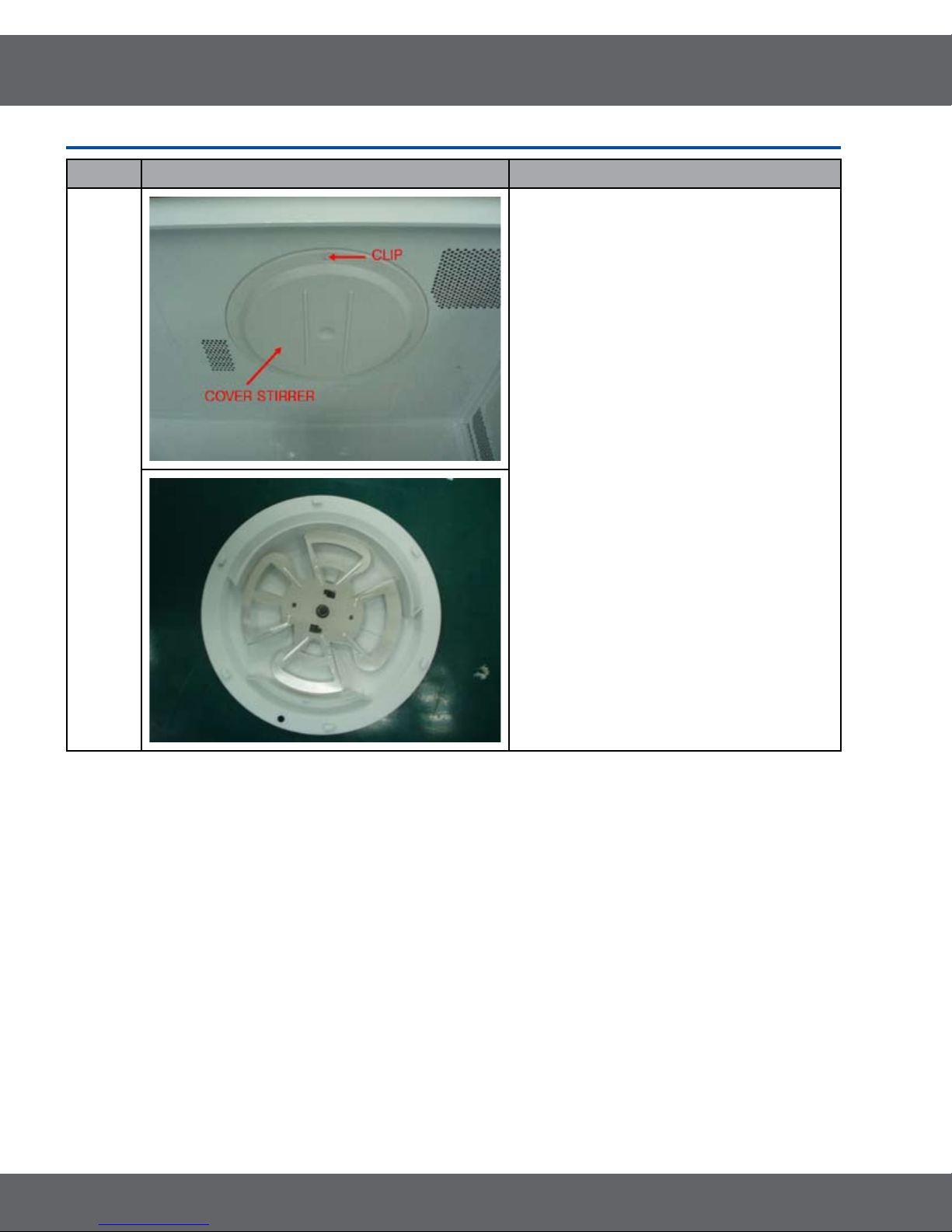
3-6 Removal of stirrer
Parts Explaination Photo Explaination
The stirrer is motor driver and located on the
upper side of the cavity. The oven uses a top
feed wave guide.
The stirrer is located in the wave guide and
the motor is located on the wave guide.
Stirrer
1. Disconnect power and open the door.
2. Remove the clip and turn the stirrer cover
left.
3. Remove stirrer cover and the stirrer will
come with it.
14
3. Disassembly and Reassembly
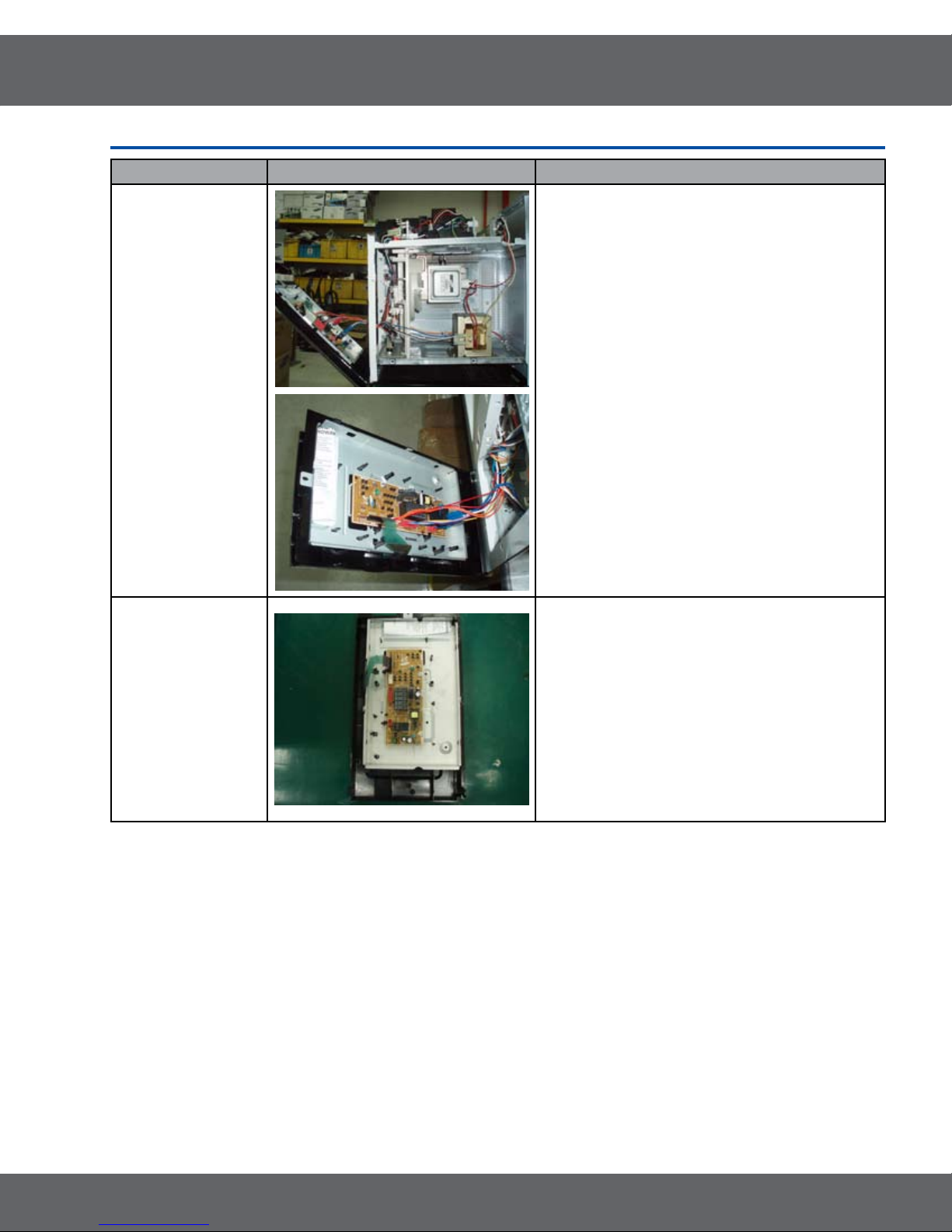
3-7 Replacement of Control Circuit Board
Parts Explaination Photo Explaination
Removal of
Control Box
Assembly
1. Disconnect power and remove grille.
2. Be sure to ground any static electric charge in
your body and never touch the control circuit.
3. Remove a screw securing the control box
assembly.
4. Disconnect the connectors from the control
circuit board.
Removal of
P.C.B Assembly
1. Pull the lever end of the plastic fastener and
remove the Flexible Printed Circuit(FPC) of
membrane panel.
2. Remove screws (4) securing the control circuit
board.
3. Lift up the control circuit board from the Ass’y
control box.
4. When reconnecting the FPC connector, make
sure that the holes on the connector are
properly engaged with the hooks on the Plastic
Fastener.
15
 Loading...