

Samsung 580TVL, SID-53 Series, SID-56 Series, SID-53N, SID-56N User Manual
...
MINI DOME CAMERA USER’S MANUAL
1
MINI DOME CAMERA USER’S MANUAL
4
Thank you for purchasing a SAMSUNG CCD CAMERA.
Before attempting to connect or operate this product,
please read these instructions carefully and save this manual for future use.
High Resolution Mini Dome Camera SID-53/56
User’s Manual
ENGLISH
P/No. : Z6806089001A
VAN 08. 04
www.samsungtechwin.com
www.samsungcctv.com
• SAMSUNG TECHWIN CO., LTD.
145-3, Sangdaewon-dong, Jungwon-gu, Seongnam-si, Gyeonggi-do, 462-120, Korea
TEL : +82-31-740-8151~8 FAX : +82-31-740-8145
• SAMSUNG OPTO-ELECTRONICS UK, LTD.
Samsung House, 1000 Hillswood Drive, Hillswood Business Park Chertsey, Surrey KT16 OPS
TEL : +44-1932-45-5308 FAX : +44-1932-45-5325
SALES NETWORK
Samsung Techwin cares for the environment at all product manufacturing
stages to preserve the environment, and is taking a number of steps to
provide customers with more environment-friendly products.The Eco mark
represents Samsung Techwin s will to create environment-friendly products,
and indicates that the product satisfies the EU RoHS Directive.
This installation should be made by a qualified service person and should conform to all
local codes.
The lightning flash with arrowhead symbol, within an equilateral triangle is
intended to alert the user to the presence of uninsulated "dangerous voltage"
within the product's enclosure that may be of sufficient magnitude to constitute a
risk of electric shock to persons.
The exclamation point within an equilateral triangle is intended to alert the user
to the presence of important operating and maintenance (servicing) instructions
in the literature accompanying the appliance.
INFORMATION-This equipment has been tested and found to comply with limits for a
Class A digital device, pursuant to part 15 of the FCC Rules. These limits are designed
to provide reasonable protection against harmful interference when the equipment is
operated in a commercial environment. This equipment generates, uses, and can
radiate radio frequency energy and, if not installed and used in accordance with the
instruction manual, may cause harmful interference to radio communications.
Operation of this equipment in a residential area is likely to cause harmful interference
in which case the user will required to correct the interference at his own expense.
WARNING- Changes or modifications not expressly approved by the manufacturer
could void the user’s authority to operate the equipment.
CAUTION : To prevent electric shock and risk of fire hazards:
Do NOT use other than specified power source.
Do NOT expose this appliance to rain or moisture.
Ultra High Resolution
By adopting a diagonal 6mm(1/3") 410,000(NTSC) pixel, 470,000(PAL) pixel SONY CCD, the
camera produces clear picture quality with a horizontal resolution of 580 TV lines for color.
Excellent Sensitivity
The built-in high sensitivity COLOR CCD enable a clear image even in 0.04 Lux or lower
illumination.
SSNR (Samsung Super Noise Reduction) Function
The high performance WIN-IV DSP chip dramatically reduces the gain noise in digital image
processing, producing clear, sharp images in low lighting environments.
Pan and Tilt
Pan and tilt are available after installing camera.
Thank you for purchasing a SAMSUNG CCD CAMERA.
Before operating the camera, confirm the camera model and proper input power voltage. In
order that you can understand this manual thoroughly, we'll introduce our model description.
SID-53 SERIES, 56 SERIES
• NTSC models : SID-53N, SID-56N • PAL models : SID-53P, SID-56P
Model Description
• SID-53X SID-56X • SIGNAL SYSTEM
N NTSC Model
P PAL Model
Signal system
This information is provided to ensure your safety and to prevent any losses, financial or
otherwise. Please read it carefully and use the product accordingly.
* For product inquiries, please contact the retail shop where you bought the camera. The use of equipment such as an
aerial ladder while providing after-sales service shall be at your expense.
* Separate the power plug when thunder crashes or lighting flashes.
* This product is support equipment for surveillance system. Therefore, we can't compensate for material loss and/or
personal injuries by robbery, fire, natural disaster or something like this type.
Ignoring this information may result in
material loss and/or serious personal
injuries including death.
Indicates “Never Allowed.”
Ignoring this information may result in
material loss and/or a slight injuries.
Indicates “No Disassembling.”
Warning/Attention/Special Mark Messages
• If the camera is exposed to spotlight or object
reflecting the strong light, smear or blooming
may occur.
• Please check the power whether it satisfies
the normal specification before connecting
the camera.
Notes
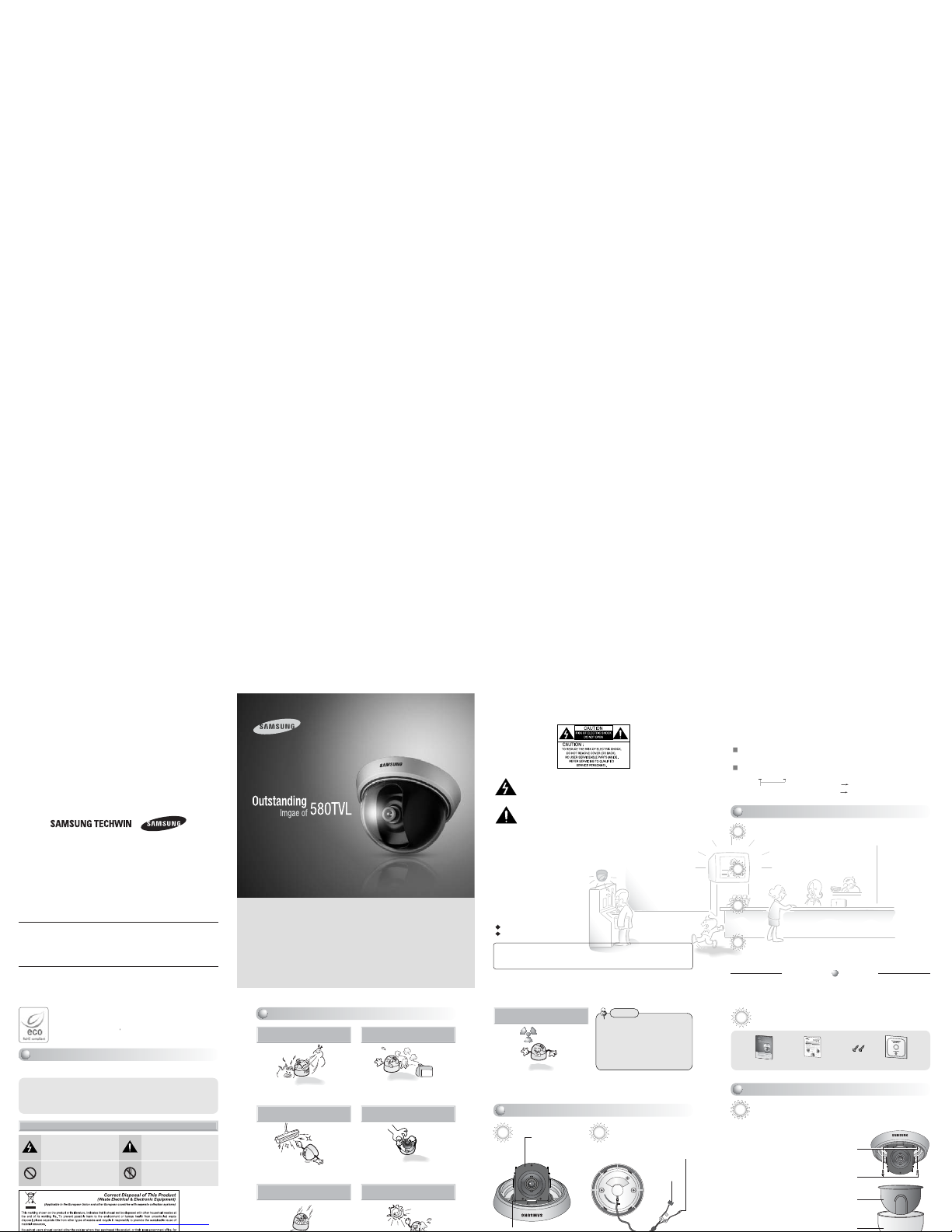
Tilt Base
You can adjust up and
down the camera
(20˚~90˚).
BNC Jack
Power Input
Terminal
Front Bottom
Do not install under extreme
temperature conditions.
Use only under temperature conditions between
-10˚C and +50˚C. Provide good ventilation when
using in high temperature conditions.
Do not expose the camera to
radioactivity.
If it is exposed to radioactivity, For heated CCD,
it will be out of order.
Do not install in high humidity
environment.
May lower image quality.
Do not install under unstable
lighting conditions.
Severe lighting changes or flickering may hinder
normal camera operation.
Avoid touching the camera lens.
The lens is the most important component of the
camera. Be careful not to smear it with fingerprints.
Do not install under unstable
lighting conditions.
Avoid touching the camera lens.
Accessories
User’s Manual
Quick Install Guide
M4 Taping
Screw 2EA
Template
Installing Camera
1. Fix the camera to a ceiling using two screws.
2. After fixing it, adjust its pan base and tilt base
properly.
3. After setting them, secure the shield
case and dome-cover.
Screw
Shield Case
Dome Cover
Hole
Features
Precautions
Getting to Know Your Camera
Installation
Warnings & Cautions
MINI DOME CAMERA USER’S MANUAL
9
MINI DOME CAMERA USER’S MANUAL
10
MINI DOME CAMERA USER’S MANUAL
11
MINI DOME CAMERA USER’S MANUAL
12
• When installing the camera on a ceiling not to disturb adjustment of Tilt Base angle fix
the BNC-Power Cable on the Pan Base clip.
Notes
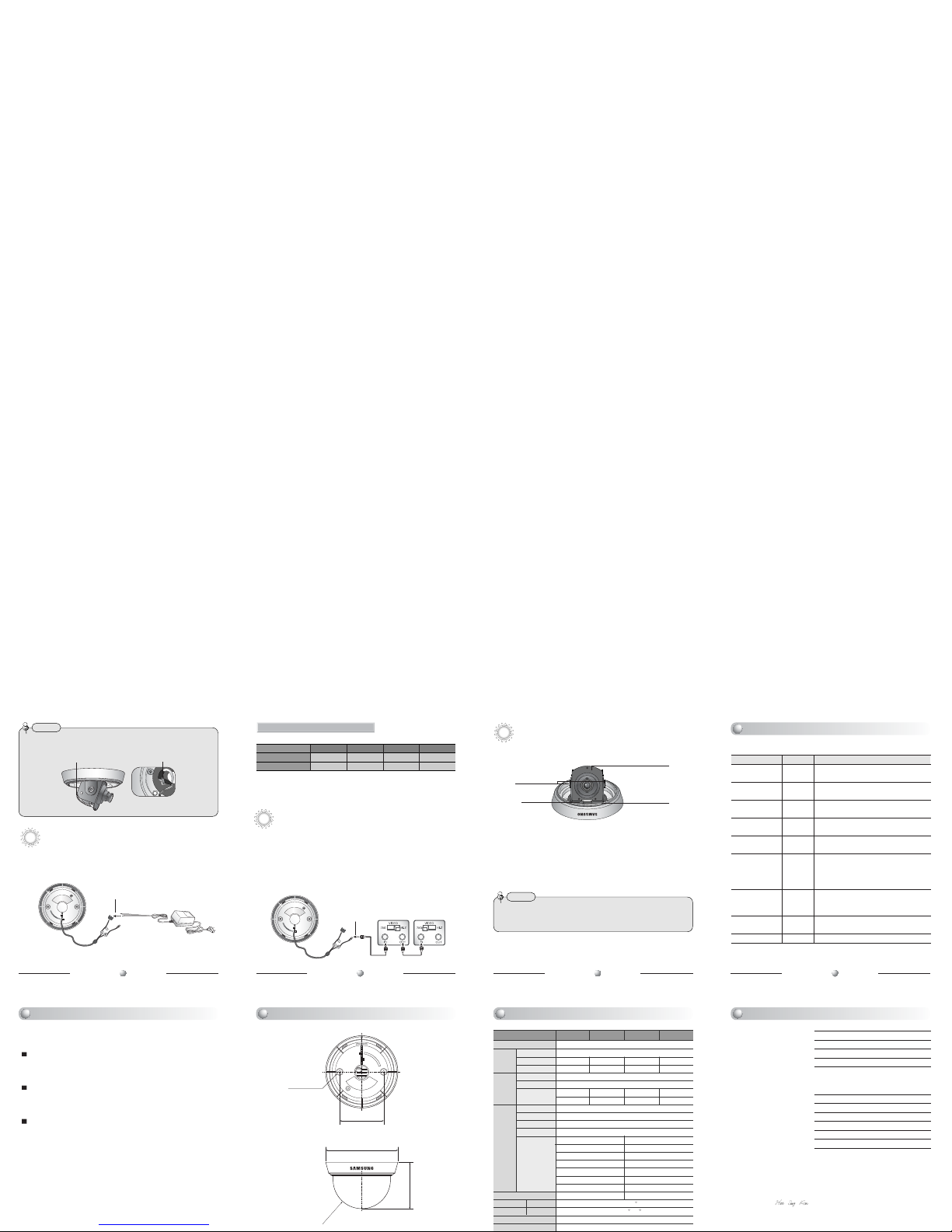
Connection to Power
•
Connect the adapter to the power input connector as shown in the figure below.
Use a DC 12V. (The Adapter is not provided with the Dome Camera.)
DOME Camera
Adapter (not provided)
Power Input Connector
DOME Camera
BNC-Power Cable
Pan Base Clip
Connection to Monitor
•
As a connecting method varies according to instruments, refer to the manual supplied
with the instrument.
•Connect the cable after power is turned off.
•Set the 75Ω / Hi-Z selection switch. If it is a intermediate device, switch it to Hi-z
and if it is final device, switch it to 75Ω. (Please refer to the Monitor Manual.)
Resistance of copper wire [at 20C˚ (68˚F)]
• As the voltage drop according to the length of the cable in the above table,
a camera may malfunction if there is an excessively long cable run.
* Voltage for camera operation: 12V DC ±10%
* Voltage drops in the above table are variable according to types of cable manufacturer.
For DC Power Type
Copper wire size (AWG)
#24(0.22mm2) #22(0.33mm2) #20(0.52mm2) #18(0.83mm2)
Resistance ( Ω/ m)
0.078 0.050 0.030 0.018
Voltage Drop (V/m) 0.028 0.018 0.011 0.006
Connect the VIDEO-OUT jack to the VIDEO-IN jack of monitor.
• After loosening Pan or Tilt Base holding screws, adjust its angle. And then tighten screws again.
• In case of adjusting the tilting, do not take the lens for preventing hysical shocks. Please take the Tilt Base.
• This dome camera is to be installed on the ceiling by factory default.
Notes
Panning & Tilting Control
You can adjust the Panning and Tilting angle freely. (Panning angle: 360°, Tilting
angle: 20°~90°)
1)
Adjustment Panning angle: After attaching the dome camera to a ceiling, adjust the
panning angle for better monitoring area by rotating the Pan Base. The panning angle
can be adjusted 360˚ freely.
2) Adjustment Tilting angle: After attaching the dome camera to a ceiling, adjust
the tilting angle for better monitoring area by rotating the Tilt Base. The tilting
angle can be adjusted to 20˚ from 90˚ freely. (based the ceiling surface)
Pan Base
You can rotate the lens
from 360˚
Tilt Base Holding
Screws
Tilt Base
You can adjust up and down
the camera (20°~90°).
Pan Base
Holding Screw
Auto Functions
Electronic Shutter
Speed
WHITE BALANCE
BACKLIGHT
GAIN CONTROL
SSNR
(Noise Reduction)
SENS UP
DAY/NIGHT
SHARPNESS
LENS SHADE
Setting
ESC
ATW
BLC
HIGH
ON
AUTO
AUTO
ON
ON
Descriptions
The shutter is controlled according to the
brightness of screen by automatically.
It can be used within the color temperature
range 1,800K~10,500K.
It helps view a desired area of picture at the
backlight condition.
The gain increases or decreases within the
range of 6dB~34dB
There is sufficient reduction in noise levels
without causing much ghost imaging.
It helps maintain a bright, clear screen image by
automatically detecting changes in the level in
low light levels without causing much ghost
imaging.
The mode is switched to Color in a normal
environment, but switches to B/W mode when
ambient illumination is low.
The outline of the video image becomes cleaner
and more distinctive.
It helps correct shading of Lens.
If you have trouble operating your camera, refer to the following.
If the guidelines do not enable you to solve the problem, contact an authorized
technician.
The image on the screen is dim.
• Check if the lens are stained. If dirty, clean the lens with soft, clean cloth.
• The image is dimmer at night than daytime. If the focus is not right, adjust it at
daytime.
The contrast on the screen is too weak.
• Adjust the contrast feature of the monitor.
• If the camera is exposed under too strong light, change the camera position.
• Adjust the lens BACK FOCUS again.
The camera is not work properly, and the surface of the camera case is hot.
• Check that you have connected the camera to a proper power (DC 12V)
SID-53N SID-53P SID-56N SID-56P
ITEM
Power Source
Sensor
Total Pixels
Effective Pixels
Scanning System
Synchronization
Frequency
Resolution
S/N(Y signal)
Video Output
Min.Illumination
Auto Functions
Lens(Built-in)
Monitoring Pan
Angle Tilt
Operating temperature/Humidity
Storing Temperature / Humidity
DC 12V±10%/Max. 1.8W
1/3 inch, Sony Super HAD CCD
811(H) x 508(V) 795(H) x 596(V) 811(H) x 508(V) 795(H) x 596(V)
768(H) x 494(V) 752(H) x 582(V) 768(H) x 494(V) 752(H) x 582(V)
2:1 Interlace
Internal Only
15.734 KHz 15.625 KHz 15.734 KHz 15.625 KHz
59.94 Hz 50.00 Hz 59.94 Hz 50.00 Hz
580 TV Lines(Min.)
52 dB (AGC Off, Weight ON)
1.0Vp-p/75Ω (Video 0.714Vp-p Sync 0.286Vp-p)
0.04 Lux/F1.2(Sens-up)
Electronic shutter speed AUTO
WHITE BALANCE AUTO
BACKLIGHT AUTO
Gain Control AUTO
SENS-UP AUTO
SSNR(Noise Control) AUTO
SHARPNESS AUTO
Fixed Lend f=3.0mm, F2.0 Fixed Lend f=6.0mm, F2.5
Manual 360
Manual 20 ~ 90
-10˚C to +50˚C / 30% to 80% RH
-20˚C to +60˚C / 30% to 90% RH
CCD
Sync.
E
L
E
C
T
R
I
C
A
L
Application of Council Directive(s) 89 / 336 / EEC
Manufacturer's Name SAMSUNG TECHWIN CO., LTD
Manufacturer's Address SAMSUNG TECHWIN CO., LTD
42, SUNGJU-DONG CHANGWON-CITY,
KYUNGNAM, KOREA, 641-120
European Representative Name
European Representative Address
Equipment Type/Environment MINI DOME CAMERA
Model Name SID-53/56
Beginning Serial NO. S6300001
Year of Manufacture 2008. 04. 01
Conformance to EN 50081-1 : 1992
EMC-Directive 89/336 EEC and 92/31/EEC
EN 50130-4 : 1996
We, the undersigned, hereby declare that the equipment specified above conforms to the above
Directive(s).
Manufacturer SAMSUNG TECHWIN CO., LTD
Legal Representative in Europe
Signature Signature
Full Name YOUNG TAEK SON Full Name
Position QUALITY CONTROL MANAGER Position
MonitorIntermediate
BNC
63.5
104
67
R41.2
2-ø4.2
Built-in functions of the SID-53, SID-56 Camera include the following
Camera Operation
Troubleshooting Dimension Specification Declaration of Conformity
 Loading...