

Samsung SID-42CN, SID-42CP, SID-22CN, SID-22CP Instruction Manual
COLOR CCD CAMERA User’s Manual
1
SAMSUNG CCD CAMERA
SID-42CN / CP
SID-22CN / CP
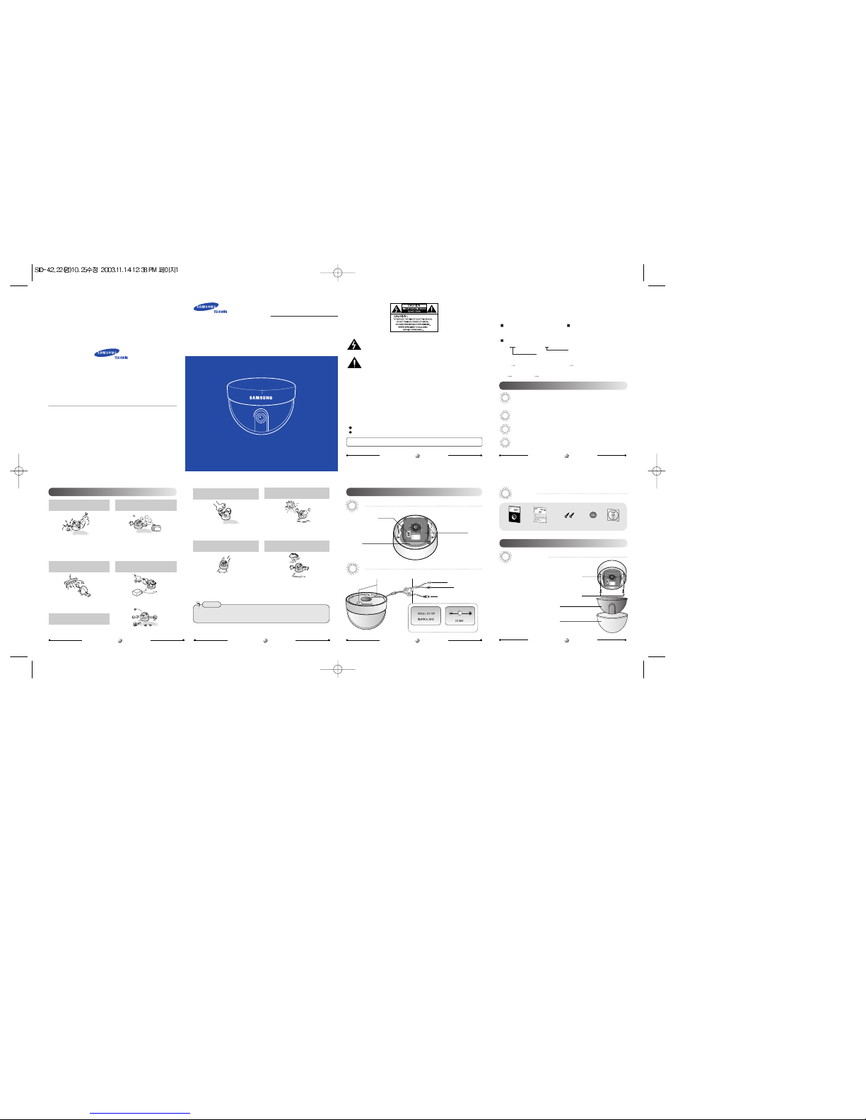
MINI DOME CAMERA
INSTRUCTION MANUAL
About this manual
Before installing and using the camera, please read this manual carefully. Be sure to keep it handy
for later reference.
P/No. : 6086-0447-01A
VAN 03. 11
•
SAMSUNG TECHWIN CO., LTD.
Optics & Digital Imaging Division 145-3,
Sangdaewon 1-Dong, Jungwon-Gu, Sungnam,
Kyungki-Do, Korea 462-703
TEL: 82-31-740-8137~41 FAX: 82-31-740-8145
•
SAMSUNG OPTO-ELECTRONICS AMERICA,
INC. (SOA)
Closed Circuit Division 40 Seaview Drive,
Secaucus N.J 07094, U.S.A
TEL: (201) 902-0347 FAX: (201) 902-0429
•
SAMSUNG OPTO-ELECTRONICS UK LTD
(SOUK)
Samsung House, 1000 Hillswood Drive Hillswood
BusinessPark Chertsey Surrey KT16 OPS
TEL: 44-(0)1932-45-5308 FAX: 44-(0)1932-45-5325
•
TIANJIN SAMSUNG OPTO-ELECTRONICS CO.,
LTD (TSOE)
7 Pingchang Rd, Nankai Dist, Tianjin, P.R China
Post Code : 300190
TEL: 86-22-2761-9698 FAX: 86-22-2761-6514
SALES NETWORK
www.samsungtechwin.com
www.samsungcctv.com
This installation should be made by a qualified service person and should conform to all local codes.
The lightning flash with arrowhead symbol, within an equilateral triangle is intended
to alert the user to the presence of uninsulated "dangerous voltage" within the
product's enclosure that may be of sufficient magnitude to constitute a risk of electric
shock to persons.
The exclamation point within an equilateral triangle is intended to alert the user to the
presence of important operating and maintenance (servicing) instructions in the
literature accompanying the appliance.
INFORMATION-This equipment has been tested and found to comply with limits for a
Class A digital device, pursuant to part 15 of the FCC Rules. These limits are designed to
provide reasonable protection against harmful interference when the equipment is
operated in a commercial environment. This equipment generates, uses, and can radiate
radio frequency energy and, if not installed and used in accordance with the instruction
manual, may cause harmful interference to radio communications. Operation of this
equipment in a residential area is likely to cause harmful interference in which case the
user will required to correct the interference at his own expense.
WARNING-Changes or modifications not expressly approved by the manufacturer could
void the user’s authority to operate the equipment.
CAUTION :To prevent electric shock and risk of fire hazards:
Do NOT use other than specified power source.
Do NOT expose this appliance to rain or moisture.
Thank you for purchasing a SAMSUNG CCD CAMERA.
Before operating the camera, confirm the camera model and proper input power
voltage. In order that you can understand this manual thoroughly, we'll introduce our
model description.
SID-42C Model Series (410,000 Pixels) SID-22C Model Series (270,000 Pixels)
SID-42CN SID-22CN
SID-42CP SID-22CP
Model Description
SID-42CX SID-22CX
• Pickup Device
42C 410,000 Pixels Color CCD 22C 270,000 Pixels Color CCD
• Signal System
N NTSC P PAL
Pickup Device
PRECAUTIONS GETTING TO KNOW YOUR CAMERA
FEATURES
INSTALLATION
Do not install the camera in extreme
temperature conditions.
Only use the camera under conditions where
temperatures are between -10˚C and +50˚C.
Be especially careful to provide ventilation
when operating under high temperatures.
Do not install or use the camera in an
environment where the humidity is high.
It can cause the image quality to be poor.
Do not touch the front glass of the
camera.
It is one of the most important parts of camera.
Be careful not to be stained by fingerprint.
Never keep the camera face to strong
light directly.
It can damage the CCD.
Do not drop the camera or subject
them to physical shocks.
It can cause malfunctions to occur.
Do not expose the camera to rain or
spill beverage on it.
If it gets wet, wipe it dry immediately.
Liquids can contain minerals that corrode the
electronic components.
Never use the camera close to a gas
or oil leak.
It can cause malfunctions to occur.
Do not install the camera under
unstable lighting conditions.
Do not disassemble the camera.
There are no user-serviceable parts inside it.
Severe lighting change or flicker can cause
the camera to work improperly.
• If the camera is exposed to spotlight or object reflecting the strong light, smear or blooming may occur.
• Please check the power whether it satisfies the normal specification before connecting the camera.
Notes
Front
High Resolution: The horizontal resolution of 480 TV lines can be achieved by using a high density
CCD having effective 410,000 pixels, which provides clean, noiseless and reliable pictures. (SID-22C
series have 270,000 pixels and can achieve 330 TV lines.)
Powerful Back Light Compensation: The BLC technology allows the camera to obtain the clear
picture, the finest detail and perfect light contrast al though there is strong light back of the subject.
Functional Selection Switches:Camera Control is available using DIP switches.
Pan and Tilt:Pan and tilt are available after installing camera
Accessories
Installing Camera
Pan Base
You can rotate the lens from 360˚
Functional Selection
Switches
You can control the
camera Using DIP Switches.
Tilt Base
You can adjust up and
down the camera(10°~90°).
Back
User Manual Quick Install Guide
Cable Rubber
Template
M4 Taping Screw 2EA
1. Fix the camera to a ceiling or a wall using two screws.
2. After fixing it, adjust its pan base and
tilt base properly.
3. After adjusting them, secure the shield case and dome-
cover.
Hole
Signal System (NTSC or PAL)
MINI DOME CAMERA USER’S MANUAL
5
MINI DOME CAMERA USER’S MANUAL
4
MINI DOME CAMERA USER’S MANUAL
3
MINI DOME CAMERA USER’S MANUAL
1
MINI DOME CAMERA USER’S MANUAL
2
MINI DOME CAMERA USER’S MANUAL
6
ScerwScerwScerw
Shield Case
Dome Cover
Hole for fixing camera Label
Power Input Terminal
Power Input Jack
BNC Jack
Label for Terminal Type Label for Jack Type

Connection to Monitor
(1) Backlight Compensation (BLC)
•
As a connecting method varies according to instruments, refer to the manual supplied with
the instrument.
•Connect the cable after power is turned off.
•Set the 75Ω / Hi-Z selection switch. If it is a intermediate device, switch it to Hi-z and if
it is final device, switch it to 75Ω. (Please refer to the Monitor Manual.)
DOME Camera
MonitorIntermediate
BNC
Connection to Power
•
Connect the adapter to the power input connector as shown in the figure below. Use a
DC 12V. (The Adapter is not provided with the Dome Camera.)
Switch it to BLC to obtain the clear picture, the finest detail and perfect light
contrast althongh there is strong backlight.
•
BLC ON: When the image is in front of strong background lighting, your camera allows you
to get the clear image.
•BLC OFF : Deactivate BLC control feature.
- To use BLC more effective, Adjust the subject to be over 20% of full screen.
- Switch to BLC OFF when the background has strong white.
If you have trouble operating your camera, refer to the following. If the guidelines do not
enable you to solve the problem, contact an authorized technician.
The image on the screen is dim.
• Check if the lens are stained. If dirty, clean the lens with soft, clean cloth.
• The image is dimmer at night than daytime. If the focus is not right, adjust it at daytime
.
The contrast on the screen is too weak.
• Adjust the contrast feature of the monitor.
• If the camera is exposed under too strong light, change the camera position.
• Adjust the lens BACK FOCUS again.
The camera is not work properly, and the surface of the camera case is hot.
• Check that you have connected the camera to a proper power (DC12V ).
Background is too bright.
• Deactivate BLC control feature.
(2) White Balance Control (ATW/AWC)
Select the desired control mode using ATW/AWC switch.
•ATW(Auto Tracing White balance): The camera automatically controls the white
balance in any environment.
•AWC(Auto White balance Control): In order to obtain the best image, menu the
switch from ATW to AWC while the camera
focuses on white paper.
DOME Camera
Adapter (not provided)
Power Input Connector
CONFIGURATION OF DIP-SWITCHES
TROUBLESHOOTING
SPECIFICATION
DIMENSION
DECLARATION OF CONFORMITY
Use the DIP switches inside of the camera for selecting functions.
• To use BLC more effective, Adjust the subject to be over 20% of full screen.
• Switch to BLC OFF when the background has strong white.
Notes
• When installing the camera on a ceiling or a wall, not to disturb adjustment of Tilt Base angle fix
the BNC-Power Cable on the Pan Base clip.
• When installing the camera on a ceiling or a wall, fuctional selection switch should be bottom-left
and switch function demo sticker under the lens.
Notes
(4) Flickerless (SID-42C Series Only)
In this function electronic shutter speed is fixed in 1/100sec(1/120sec: PAL
model). FL function can compensate the flicker caused by power frequency,
but set OFF in the area not using a 60Hz(50Hz: PAL model) AC power.
(3) Sharpness
The switch emphasize the sharpness. To soften the edge move this Swich
to Normal.
•After loosening Pan or Tilt Base holding screws, adjust its angle. And then tighten screws again.
•AWC(Auto Balacne Control): In order to obtain the best image, mode the switch from ATW to AWC
while the camera focuses on white paper.
•In case of adjusting the tilting, do not take the lens for preventing hysical shocks. Please take the Tilt Base.
• This dome camera is to be installed on the ceiling by factory default. In case of using camera on the wall,
readjust the Tilt angle as page 7 (Notes).
Notes
Panning & Tilting Control
You can adjust the Panning and Tilting angle freely. (Panning angle: 360°,
Tilting angle: 10°~90°)
1)
Adjustment Panning angle: After attaching the dome camera to a ceiling or a wall, adjust the
panning angle for better monitoring area by rotating the Pan Base. The panning angle can be
adjusted 360°freely.
2) Adjustment Tilting angle: After attaching the dome camera to a ceiling or a wall, adjust
the tilting angle for better monitoring area by rotating the Tilt Base. The tilting angle can
be adjusted to 10°from 90° freely. (based the ceiling surface)
Pan Base
You can rotate the lens from 360˚
Tilt Base Holding Screws
Tilt Base
You can adjust up and down
the camera (10°~90°).
SIC-22CN SIC-22CP SIC-42CN SIC-42CP
Item
Input power
Power Consumption
Operating
& Humidity
Dimension
Weihgt
Pickup Device
Video Output
Min. illumination
Synchronizaion
S/N
Resolution
Lens (Built-in)
ESC
White Balance
BLC
Shrpness
Flickerless
Monitoring Pan
Angle Tilt
DC 12V ±10%
1.4W 1.5W
-10C˚ ~ +50C˚ [-14˚F ~ 122˚F] / 30% ~ 90% RH
85.5mm(Ø) x 68mm(H)
160g
1/3” color interline-transfer CCD
1Vp-p Composite 75Ωunbalanced
0.4Lux / F1.2 0.7Lux / F1.2
INT
more than 48dB (Weight ON)
more than 330TV Line more than 480TV Line
Fixed Lens 92˚, Focal Length 3.7mm, F2.2
1/60(1/50) ~ 1/120,000sec
ATW / AWC Selectable
ON / OFF Selectable
High / Normal selectable
Not Used ON / OFF selectable
360˚
10˚ ~ 90˚
Application of Council Directive(s) 89 / 336 / EEC
Manufacturer's Name SAMSUNGTECHWIN CO., LTD
Manufacturer's Address SAMSUNGTECHWIN CO., LTD
42, SUNGJU-DONG CHANGWON-CITY,
KYUNGNAM, KOREA, 641-120
European Representative Name
European Representative Address
Equipment Type/Environment MINI DOMECAMERA
Model Name SID-42CP / 22CP
Beginning Serial NO. S3B00001
Year of Manufacture 2003. 11. 1
Conformance to EN 50081-1 : 1992
EMC-Directive 89/336 EEC and 92/31/EEC
EN 50130-4 : 1996
We, the undersigned, hereby declare that the equipment specified above conforms to the above
Directive(s).
Manufacturer SAMSUNGTECHWIN CO., LTD
Legal Representative in Europe
Signature Signature
Full Name YOUNG TAEK SON Full Name
Position QUALITY CONTROL MANAGER Position
Place CHANGWON, KOREA Place
Date 2003. 11. 1 Date
Resistance of copper wire [at 20C˚ (68˚F)]
• As the voltage drop according to the length of the cable in the above table, a camera may
malfunction if there is an excessively long cable run.
* Voltage for camera operation: 12V DC ±10%
* Voltage drops in the above table are variable according to types of cable manufacturer.
For DC Power Type
Copper wire size (AWG)
#24(0.22mm2) #22(0.33mm2) #20(0.52mm2) #18(0.83mm2)
Resistance ( Ω/ m) 0.078 0.050 0.030 0.018
Voltage Drop (V/m) 0.028 0.018 0.011 0.006
SID-42C Series
SID-22C Series
Connect the VIDEO-OUT jack to the VIDEO-IN jack of monitor.
MINI DOME CAMERA USER’S MANUAL
9
MINI DOME CAMERA USER’S MANUAL
8
MINI DOME CAMERA USER’S MANUAL
7
MINI DOME CAMERA USER’S MANUAL
10
MINI DOME CAMERA USER’S MANUAL
13
MINI DOME CAMERA USER’S MANUAL
12
MINI DOME CAMERA USER’S MANUAL
11
Pan Base Holding Screw
Ø 85.5mm
Ø 63mm
68mm
<Installing the camera on a ceiling> <Installing the camera on a wall>
Functional selection switch
BNC-Power Cable
Switch functional demo sticker
 Loading...