

Page 1

CONTROLLER
User Manual SIC-0400
Page 2

Controller
User Manual
Copyright
©2010 Samsung Techwin Co., Ltd. All rights reserved.
Trademark
The name of this product is the registered trademark of Samsung Techwin Co., Ltd.
Other trademarks mentioned in this manual are the registered trademark of their respective company.
Restriction
Samsung Techwin Co., Ltd shall reserve the copyright of this document. Under no circumstances, this document shall be
reproduced, distributed or changed, partially or wholly, without formal authorization of Samsung Techwin.
Disclaimer
Samsung Techwin makes the best to verify the integrity and correctness of the contents in this document, but no formal
guarantee shall be provided. Use of this document and the subsequent results shall be entirely on the user’s own responsibility.
Samsung Techwin reserves the right to change the contents of this document without prior notice.
Warranty
If the product does not operate properly in normal conditions, please let us know. Samsung Techwin will resolve the problem
for free of charge. However, the followings are excluded:
If the system behaves abnormally because you run a program irrelevant to the system operation.
•
Deteriorated performance or natural worn-out in process of time
•
is the registered logo of Samsung Techwin Co., Ltd.
Page 3

overview
IMPORTANT SAFETY INSTRUCTIONS
Read these instructions.
1.
Keep these instructions.
2.
Heed all warnings.
3.
Follow all instructions.
4.
Do not use this apparatus near water.
5.
Clean only with dry cloth.
6.
Do not block any ventilation openings
7.
Do not install near any heat sources such as radiators, heat
8.
that produce heat.
Do not defeat the safety
9.
wider than the other. A grounding type plug has two blades and a third grounding prong. The wide blade or the third
prong are provided for your safety. If the provided plug does not fi t into your outlet, consult an electrician for replacement of the obsolete outlet.
Protect the power cord from being walked on or pinched particularly at plugs, convenience receptacles, and the
10.
point where they exit from the apparatus.
Only use attachments/ accessories specifi ed by the manufacturer.
11.
Use only with the cart, stand, tripod, bracket, or table specifi ed by the manufacturer, or sold with
12.
the apparatus. When a cart is used, use caution when moving the cart/apparatus combination to
avoid injury from tip-over.
Unplug this apparatus during lighting storms or when unused for long periods of time.
13.
Refer all servicing to qualifi ed service personnel. Servicing is required when the apparatus has been
14.
damaged in any way, such as power-supply cord or plug is damaged, liquid has been spilled or objects have fallen into
the apparatus, the apparatus has been exposed to rain or moisture, does not operate normally, or has been dropped.
purpose of the polarized or grounding-type plug. A polarized plug has two blades with one
. Install in accordance with the manufacturer’s instructions.
resistors, stoves, or other apparatus (including amplifi ers)
● OVERVIEW
English _3
Page 4
overview
WARNING
TO REDUCE THE RISK OF FIRE OR ELECTRIC SHOCK, DO NOT EXPOSE THIS PRODUCT TO RAIN
OR MOISTURE. DO NOT INSERT ANY METALLIC OBJECT THROUGH THE VENTILATION GRILLS OR
OTHER
Apparatus shall not be exposed to dripping or splashing and no objects filled with liquids, such as vases,
shall be placed on the apparatus.
CAUTION
EXPLANATION OF GRAPHICAL SYMBOLS
OPENINGS ON THE EQUIPMENT.
CAUTION
RISK OF ELECTRIC SHOCK.
DO NOT OPEN
:
CAUTION
REFER SERVICING TO QUALIFIED SERVICE PERSONNEL.
The lightning flash with arrowhead symbol, within an equilateral triangle, is intended to alert
the user to the presence of “dangerous voltage” within the product’s enclosure that may be
of sufficient magnitude to constitute a risk of electric shock to persons.
TO REDUCE THE RISK OF ELECTRIC SHOCK.
DO NOT REMOVE COVER (OR BACK).
NO USER SERVICEABLE PARTS INSIDE.
The exclamation point within an equilateral triangle is intended to alert the user to the
presence of important operating and maintenance (servicing) instructions in the literature
accompanying the product.
Please read the following
y
Do not Place this apparatus on an uneven surface.
y
Do not install on a surface where it is exposed to direct sunlight, near heating equipment or
extremely
y
Do not place this apparatus
y
Do not attempt to service this apparatus yourself.
y
Do not place a glass of water on the product.
y
Do not install near any magnetic sources.
y
Do not block any ventilation openings.
y
Do not place heavy items on the product.
4_ overview
cold area.
recommended safety precautions carefully.
near conductive material.
in
Page 5
User’s Manual is a guidance book on how to use the product.
Below is a key to the following signs that are used in this manual.
y
Reference: Providing useful information for the user.
y
Notice: If the instructions are not followed correctly damage to the goods or person may occur.
Ú
For safety please read this manual for the before using of goods and keep it in the safe place.
Samsung Techwin cares for the environment at all product manufacturing stages, and is taking measures to provide
customers with more environmentally friendly products.
The Eco mark represents Samsung Techwin’s devotion to creating environmentally friendly products, and indicates
that the product satisfies the EU RoHS Directive.
Correct Disposal of This Product (Waste Electrical & Electronic Equipment)
(Applicable in the European Union and other European countries with separate collection systems)
This marking on the product, accessories or literature indicates that the product and its electronic accessories (e.g.
charger, headset, USB cable) should not be disposed of with other household waste at the end of their working life.
To prevent possible harm to the environment or human health from uncontrolled waste disposal, please separate
these items from other types of waste and recycle them responsibly to promote the sustainable reuse of material
resources.
Household users should contact either the retailer where they purchased this product, or their local government
office, for details of where and how they can take these items for environmentally safe recycling.
Business users should contact their supplier and check the terms and conditions of the purchase contract. This
product and its electronic accessories should not be mixed with other commercial wastes for disposal.
● OVERVIEW
English _5
Page 6

overview
CONTENTS
OVERVIEW
3
INSTALLATION
10
CONNECTING WITH OTHER DEVICES
11
OPERATION INSTRUCTIONS
16
3 Important Safety Instructions
8 Key Features
9 What’s Included
10 Precautions
11 Internal wiring
14 Control panel Installation
16 Control Panel overview
17 Powering up the panel
18 Alarm types
18 Alarm Mode
18 Keypad locked and unlocked
19 Zone Instruction
6_ overview
FUNCTION KEY OPERATION
20
SYSTEM PROGRAMMING
22
20 Arm-away
20 Arm-stay
21 Disarm
21 Panic
22 Enter programming status
22 System Parameter Setting
30 Programming status exiting
Page 7

REMOTELY CONTROL THROUGH
TELEPHONE
31
31 Remotely control panel through dialing
32 Control panel alarms through telephone
● OVERVIEW
APPENDIX
33
33 Technical parameter
38 Specifications
English _7
Page 8

overview
KEY FEATURES
This product is a 4 wired zones dialing alarm control panel. It transmits the alarm information via telephone communication
network and is remotely controlled to deal with emergencies in time, ensuring user's personal and property safety. This
product has complete functions, flexible configuration, strong destroy protection and convenient operations, being suitable
for residences, stores, factories, warehouses, banks, schools and hospitals, etc.
4 programmable wired zones: Selectable to accessories like fi reproof, burglar alarm sensor, glass break sensor etc.
1.
6 alarm telephone numbers: 2 for receiving centre and 4 for private telephones
2.
Option to whether send alarm to receiving centre or not
3.
Communication protocol: ADMECO 4+1/Contact
4.
Dial to receiving centre, personal cell phone and fi xed telephone to alarm
5.
Remote control through telephone
6.
Bell output, buzzer indication
7.
Bell callback function
8.
9.
Three passwords: 1 user code+1 duress code +1 operation password
10.
Restore user password and operation password to factory default by wire jumper
11.
Restore system parameter to factory default via program setting
12.
250 events record
13.
System Self-checking
14.
Bypass direction
15.
Mulfuction direction
Tamper function of control panel
16.
Malfunction alarms for AC power loss, battery low-voltage and telephone line loss
17.
❖
Terms definitions
•
Detector: A facility that detects intrusion and abnormal state automatically via some electric or physical methods
and outputs switch signals to the system for disposal, then generate alarm signals, such as infrared detector, etc.
•
Protection Zone: An area within the detection range of one or one group of detectors.
•
Bypass: Close one of the zones temporarily, so that it can not alarm while act in the zone.
•
Arm-away: The armed status while going out. All the zones without bypass are in armed status.
•
Arm-stay: The armed status at night. All the zones are in armed status except active zones during arm-stay.
•
Disarm: Cancel the alarm information that has happened. Close the entry/exit zones, active zones, perimeter
zones. Other zones are still in armed status
•
24-hour zone: No matter armed or disarmed, it is in valid detecting status. It is usually used in fire alarm, duress
alarm and other emergent alarm which can be cancelled only by password holder.
•
Alarm receiving center station: It is a telephone voice system that can receive telephone call from the control panel
and indicate by video and audio.
ID.
8_ overview
Page 9
•
Entry delay: when entry/exit zone or active zone is triggered, a period can be set for user to disarm the system
before alarm. During the period, the control panel will not alarm immediately and the buzzer chirps "Di" indicating
delay started, user need to disarm the system in time. If the system is not disarmed before delay finished, the
control panel will alarm.
•
Exit delay: A period for user to leave detecting area to set arm-away. During this period, if the entry/exit zone and
active zone is triggered, the control panel will not alarm.
•
User address code: 4 digits code used to be distinguished by the alarm center when the control panel with
network alarms.
•
User password: It is capable of arming/disarming and programming system parameter.
•
Operation password: It is capable of arming/disarming, but disable to program system parameter.
•
Duress password: When user is forced to disarm the control panel by burglar, user inputs duress password, the
control panel is disarmed but sends alarm information to the alarm center or receiver. The duress password can
be used to disarm but not set parameters. The duress password is the last digit of user password plus 1 without
carry (9+1=0). E.g. while user password is 8889, the duress password is 8880; while user password is 9999, the
duress password is 9990.
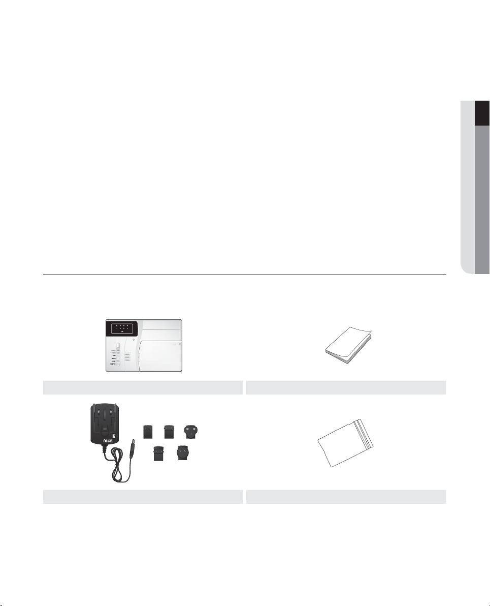
WHAT’S INCLUDED
Unpack the product package and place the product on the floor or a flat surface.
Check if the following components are all included in the product package.
● OVERVIEW
Control Panel User Manual
Adapter Accessories Bag
There are 4 line resistors (2.2k), 4 screws and a expansion tube, tamper spring in the attachment bag.
M
English _9
Page 10

installation
PRECAUTIONS
•
Please read the instruction manual to get an overview of the product before using it.
•
Refer to the "Installing the system" to install the system correctly (include detector, control panel, telephone line, bell etc.)
•
Read the "Control panel overview" carefully to understand the information of the control panel.
•
Refer to the "Power connection" to connect the power correctly.
•
The system will be in initialization state after connecting the power: the keypad back light is on, all LED flash once, the
buzzer chirps "Di", the bell sounds and the power indicator is on, indicating the system works normally.
•
Setting before using: Refer to the "System Programming", input telephone number of the alarm receiving center, receiving
center number and control panel address code to finish the setting of learn code of detector and remote controller and
protection zones.
•
Refer to the arm/disarm the system
•
Work out a protection scheme based on user protection zone requirements, then decide the type and rating of the
detector.
•
Confirm the installation position and wiring direction according to the specific environment. Make sure the position invisible
without affecting its reliability.
•
The construction scheme and engineering drawings must be filed for later maintenance.
10_ installation
Page 11
connecting with other devices
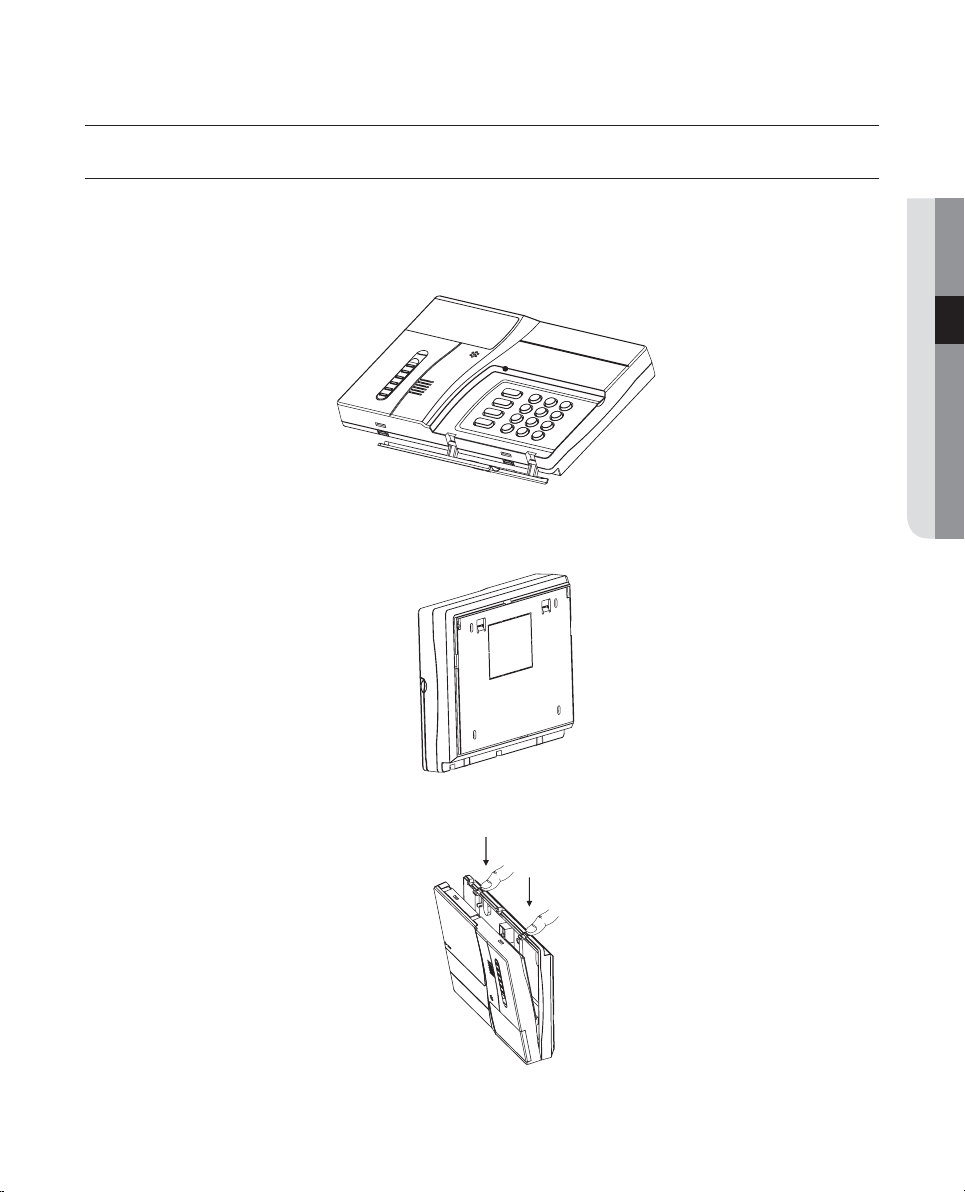
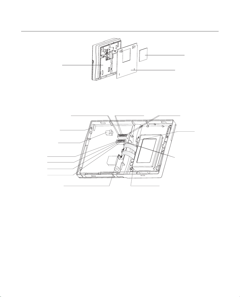
INTERNAL WIRING
•
According to the figure to wire the power line, bell line, telephone line and detector line in wired zone.
•
Two ways for line exiting: (1) from the line exit at the back cover of the control panel. Get rid of the rubber sheet of the
interface before exiting. (2) from the exit cover of the panel board. Get rid of the line cover before exiting.
Figure 1: Control panel
● CONNECTING WITH OTHER DEVICES
Figure 2: The back of the control panel
Figure 3: Open the control panel
English _11
Page 12
connecting with other devices
Line exit cover
Back cover
Hanging board
Figure 4
Tamper switch
DC socket
Wired Zone Z1
Wired Zone Z2
Wired Zone Z3
Wired Zone Z4
Telephone line entry
Password restore jumper
line output Bell output
Telephone
Figure 5: Internal View
Battery
Switch
AUX power output
Battery Socket
12_ connecting with other devices
Page 13

Power connection
•
Power Adoption: Input 100V~240V AC 50/60Hz 0.3A, output 12V DC 1A: insert the output plug of the adaptor in the
DC socket. (Refer to the figure 5)
•
7.2V Ni-MH rechargeable battery as standby power, connect the power with the control panel via 8pin cable, then
put the power cord with plug in the standby battery socket, finally, turn the standby battery switch KP1 on (Refer to
the figure 4). If the battery is well charged, it can supply the system with power about 8 hours.
It takes about 16 hours to well charge the standby battery; when the battery is low-voltage, it may work for a period of time, please
M
check the failure of AC power during this period; after AC power works normally, the standby battery will be charged automatically by
the system.
•
About power indicator instruction, please refer to "Control Panel overview".
Siren connection
•
The biggest drive capacity of bell terminal (+BELL-) is 400mA /12V DC.
•
Connect the two power lines of the bell to "BELL +" and "BELL -" terminals. (Refer to figure 5)
•
When the system is powered up and initialized, bell will chirp once, indicating it works normally. Setting the bell on/off
and the chirping time with keyboard.
Wired zone connection
System supports different types of detector, and each wired loop is connected to an end-of-line(EOL) resistor.
For different detectors, modes of connection are shown as followed:
•
When connecting N.C. detector, connection mode:
ZONE
2.2 KΩ
● CONNECTING WITH OTHER DEVICES
G
N.C. Detector connection figure
•
When connecting N.O. detector, connection mode:
ZONE
G
N.O. Detector connection figure
2.2 KΩ
English _13
Page 14

connecting with other devices
Phone line connection
•
Connect telephone line to 'LlNE_IN' interface of the control panel (Refer to the figure 5)
•
Connect telephone or facsimile machine to 'LINE_OUT' interface of the control panel. (Refer to the figure 5)
•
Under the telephone line loss checking status, the indicator on control panel will be on and the buzzer will chirp "Di-Di" for
1 minute, after disarmed, the buzzer will be off; the indicator is off means the telephone line is connected correctly.
AUX Power Output Terminal
•
AUX supplies power output for wired detectors (AC Operated : 10-12V, Battery Operated : 6-8V, max current :
200mA. It may cause abnormal working for wired detector under low battery.)
CONTROL PANEL INSTALLATION
•
The system should be mounted in a position which allows convenient access to AC power and telephone line.
•
Please use standby power to ensure the control panel work normally when electric network fails.
•
Fix the control panel to the wall by screws. Interval between screws in the same row is 150mm and vertical intervals
between screws in two rows are 98mm. Nail 4 screws in the wall and hang the control panel on the screws. (Refer to the
figures below.)
Line Exit
14_ connecting with other devices
Figure 6
Line Exit
Figure 7
Page 15

Figure 8
● CONNECTING WITH OTHER DEVICES
English _15
Page 16

operation instructions
CONTROL PANEL OVERVIEW
Zone Alarm Indicators
POWER
PROG
ARM
WARN
PANIC
TAMPER
Figure 9
•
"POWER" indicator
Flash quickly - standby power low-voltage (or not connect standby power)
Flash slowly -- standby power works normally, AC power is low-voltage
Always on ---- standby power and AC power is in normal working status
Standby power low-voltage (or not connect standby power), or the AC power low-voltage, the buzzer will chirp "Du-Du" for
M
1 minute, after disarmed, the buzzer will be off.
•
"PROG" indicator
Always on --- inquiry alarm events/zone information (if the zone is bypassed)
Flash --------- in programming status
Off ----------- exit programming status
The indicator will fl ash when the system is in programming status, indicating user can program the control panel by entering
M
commands with keypad; In programming status, enter the command of inquiring event recording/zone is bypassed or not, the
indicator is on all the time, indicating the system is inquiring events recording/zone is bypassed or not; the indicator fl ashes when
enter "¶" or "#" to exit inquiring status.
•
"ARM" indicator
Always on --- in arm-away status
Flash --------- in arm-stay status
Off ----------- in disarmed status
•
"WARN" indicator
Always on --- no or fault connection of telephone line
Flash slowly -- dial alarm receiving center
Flash quickly - continuously fail to communicate with alarm receiving center for 5 times
When the telephone line is disconnected or connected incorrectly, "WARN" indicator will be on all the time and the buzzer
M
will sounds "Di-Di" for 1 minute and stop chirping after disarmed; the "WARN" indicator will be off when the telephone line is
connected correctly. When the duress zone disarmed, dial alarm receiving center, the "WARN" indicator will not fl ash.
16_ operation instructions
Page 17

•
"PANIC" indicator
Flash quickly - alarm for help
Flash slowly -- panic
Always on ---- events recording/bypass indication
When press "PROG" on keyboard or "PROG" on remote controller for 2s, the indicator will flash quickly and
generate panic alarm.
When inquiry the events recording, the indicator will be on all the time if the alarm is triggered by panic key.
When inquiry the panic key is bypassed or not, if it is, the indicator will be on all the time.
•
"TAMPER" indicator
Flash quickly - tamper alarm
Flash slowly -- control panel tamper is bypassed
Always on ---- events recording/bypass indication
When open the cover, the control panel will generate tamper alarm and the indicator will flash quickly; if the control
panel does not alarm when open the cover, the tamper zone must be bypassed.
When read the events recording, the indicator will be on all the time if alarm is triggered by tamper switch.
When inquiry control panel tamper is bypassed or not, the indicator will be on all the time if tamper is bypassed.
•
"Zone alarm" indicators
Flash quickly - zone alarm
Flash slowly -- zone bypassed
Always on ---- events recording/bypass indication
When looking up the history, the corresponding alert indicator will keep lit if a zone alert exists;
When checking whether a zone is set bypass, the corresponding alert indicator will keep lit if a bypass exists;
If a zone is set to non-24-hour zone and is disarmed, it does not give alarm when trigged, but the corresponding
alert indicator will keep lit, indicating a malfunction alert in the zone, and goes off when the problem is resolved.
When the zone type of a zone is set to Duress by programming, corresponding alert indicators of the zone will not
turn on or blink.
•
Key
Four function keys: AWAY, STAY, DISARM and PROG keys.
The PROG key is a compound key and the other function is for panic. (Press for 2s) Digit key, "¶" key and "#" key
are used in programming and relevant operations. "#" key is used to confirm the input; "6" and "9" are used to
turn pages while inquiring event records continually.
•
Backlight
As long as any key is pressed, buzzer sounds "Di" and back light is on for 30 seconds
key is bypassed
● OPERATION INSTRUCTIONS
POWERING UP THE PANEL
•
Check line connection again, ensuring all lines are connected correctly.
•
Switch on AC power or turn on the standby power; back light of the keypad and all LED will be on and the buzzer chirps
"Di-Di" for several times, the outside siren sounds once and power indicator is on.
English _17
Page 18

operation instructions
ALARM TYPES
Control panel alarm: Zone alarm and trouble alarm.
•
Zone alarm
When the 24 hours zone is triggered, the control panel will alarm at once.
When the entry delay zone is triggered, it will provide entry delay, the buzzer chirps tightly to warn the user that the system
must be disarmed. If the panel is not disarmed before the entry delay expires an alarm will be generated.
When the entry delay zone is alarming, if it is be triggered again, there is no entry delay and the control panel will alarm at once.
M
•
Trouble alarm
AC power failure, low voltage and telephone line loss. When there is trouble alarm, the corresponding indicator will be on,
the buzzer chirps "Di-Di" for 1 minute and will be off after user disarms the system.
ALARM MODE
Alarm Type Alarm Center Phone Alarm Alarm Indicator Buzzer Bell
Fire zone Yes Yes Flash quickly Chirp (time adjustable) Chirp (time adjustable)
Gas zone Yes Yes Flash quickly Chirp (time adjustable) Chirp (time adjustable)
Panic zone Yes Yes Flash quickly Chirp (time adjustable) Chirp (time adjustable)
Perimeter zone Yes Yes Flash quickly Chirp (time adjustable) Chirp (time adjustable)
Active zone Yes Yes Flash quickly Chirp (time adjustable) Chirp (time adjustable)
Entry / Exit zone Yes Yes Flash quickly Chirp (time adjustable) Chirp (time adjustable)
Duress zone Yes Yes / Muted Muted
Tamper zone Yes Yes Flash quickly Chirp (time adjustable) Chirp (time adjustable)
Telephone line
loss
AC power failure Yes No Flash slowly Chirp for 1 minute Muted
DC low-voltage Yes No
No No On Chirp for 1 minute Muted
Flash quickly Chirp for 1 minute Muted
KEYPAD LOCKED AND UNLOCKED
•
When continuously enter password incorrectly for 5 times, the keyboard will be locked, if the user operate the panel in this
state, the back light flashes twice and the buzzer chirps for 5 times to indicate the operation is invalid.
•
When there is no zone alarming and the keypad is locked, then if there is zone alarm, the system will unlock automatically.
•
When there is zone alarming and the keypad is locked, the user must cut off the power and re-start the system to unlock
the keyboard, or the system will unlock automatically after half hour.
18_ operation instructions
Page 19

ZONE INSTRUCTION
Zone type
● OPERATION INSTRUCTIONS
Zone type
Entry/Exit zone Invalid Valid Valid Yes Yes Yes Gate 01
Active zone Invalid Valid Invalid Yes Yes Yes Indoor 02
Perimeter
zone
Panic zone Valid Valid Valid No No Yes Panic button 04
Fire zone Valid Valid Valid No No Yes Fire sensor 05
Gas zone Valid Valid Valid No No Yes Gas sensor 06
Tamper zone Valid Valid Valid No No Yes Tamper device 07
Duress zone Valid Valid Valid No No No
Valid or not
when disarm
Invalid Valid Valid No No Yes
Valid or not
when go out
Valid or not
when stay in
Exit delay Entry delay
Flash & Sound
alarm
Mounted
position or
detector
Veranda or
Window
Emergency
button
Type No
Zone number
•
Wired zone: 01~04
•
Panic zone: 17
•
Duress alarm: 18
•
Tamper: 30
03
08
English _19
Page 20

function key operation
The operation of arm-away, arm-stay, disarm, and panic can be achieved by using the function keys on keypad. If the
system connects to central station, all operation information can be sent to central station. If sending information to central
station must be charged, user can choose just send zone alarm information to central station.
ARM-AWAY
It is applied when the user goes out.
•
When the system is in disarm/arm-stay status and no zone alarm, (not include duress zone alarming), press "Arm-away"
key on the control panel, arming indicator is on, buzzer begins to sound "Di-Di" to indicate exit delay starts. The buzzer will
be off until exit delay finished; the system is in Arm-away status.
•
When the system is in zone alarm status, (not include duress zone alarming) pressing "Arm- away" key on the control
panel is invalid, the buzzer chirps.
•
In Arm-away status, Press "Arm-away"key on control panel is invalid, the buzzer chirps.
•
When the system is in programming status, it is no use to press the "Arm-stay" key on the control panel, the buzzer chirps
"Di-Di";
ARM-STAY
The arming mode can be applied when user stay at home. In this case, "Active zone" is invalid.
•
If the control panel is in "Arm-away" status and no zone alarms, press the "Arm-stay" key on control panel, input password
(user password or operation password) to enter arm-stay status or press the "Arm-stay" key on remote controller to enter
the arm-stay status directly. Press "Arm-stay" key → user password (or operation password) → press "#" key
•
If the password is correct, the buzzer chirps "Di-Di" once, indicating enter "Arm-stay" status, then the arm indicator
flashes; If the password is incorrect, the buzzer chirps for 5 times. If enter the error password continuously for 5 times, the
keypad will be locked automatically. Press "Arm-stay" on remote controller to enter into Arm-status directly, the buzzer
chirps and the arm indicator flashes.
If the control panel is in zone alarm status (duress zone alarm excluded), pressing the "Arm-stay" key on the control panel
is invalid, the buzzer chirps "Di-Di" to indicate the operation is invalid; the user has to disarm first and then arm.
•
If the system is in arm- stay status, it is no use to press "Arm-stay" key on the control panel, the buzzer chirps "Di-Di".
•
If the system is in programming status, press the "Arm-stay" key on the control panel is invalid, the buzzer will chirp "Di-Di"
to indicate this valid operation.
20_ function key operation
Page 21

DISARM
When the system is in programming status, disarm after exiting programming status.
•
Operation with keypad: press "disarm" key → user password (or operation password) → ("0") → "#"
•
Enter user password or operation password adding "0" to the end, means not keep disarming of alarm indication, the bell and
buzzer are muted after disarming, and the alarm indicator is off. If the password without adding "0" means keep disarming of
alarm indication, the bell and buzzer are muted after disarming, the alarm indicator flashes; The buzzer chirps "Di" indicating
disarm successfully, if the buzzer chirps "Di" for 5 times indicating disarm failure. Disarm the system again as above.
PANIC
Press the "PROG" key of the control panel or the "Panic" key of the remote controller for 2 seconds, the control panel will
alarm, panic indicator flashes quickly, buzzer chirps continually. (chirp time adjustable)
● FUNCTION KEY OPERATION
English _21
Page 22

system programming
system programming
ENTER PROGRAMMING STATUS
The system should be in programming status to modify system parameters.
When the system is armed, user must disarm the system, or will disable to enter programming status. Operation: (disarm
→
press "PROG" key → "user password" → "#"
status)
If the password is correct, the buzzer chirps "Di" and the indicator flashes, indicating the system is in programming status; if
the password is incorrect, the buzzer chirps 5 times. If enter the
will be locked automatically.
When the system is in arm status (or in programming status), pressing the "PROG" button, the buzzer chirps "Di-Di" for 4 times quickly,
M
indicating the operation is invalid; no button is pressed for 1 minute and the buzzer chirps "Di-Di" for 4 times, indicating exit programming
status.
incorrect password continuously for 5 times, the keyboard
SYSTEM PARAMETER SETTING
In programming status, set the system with the command code without password.
Telephone number setting/canceling (Enter : 11XY...Y)
Telephone number setting
1.
Operations: (PROG → user password → #) → 11 → X → Y ... Y → #
Bracket means in programming status, it is not necessary to enter PROG → user password → #, just input commands
directly.
Parameters setting: X=1~6, indicates 1~6 groups telephone, 1~2 are alarm numbers of the alarm receiving center, 3~6
are personal telephone numbers.
Y ... Y: Indicates telephone number needed to dial (1~15 digits), Telephone number is null in factory setting.
Functions: The system can be set 6 groups of alarm receiving telephone, Number 1~2 are alarm numbers of the alarm
receiving center, User sets the first number
automatically and sent out alarm information. The alarm center will take corresponding actions after receiving the alarm
and alarm indicator flashes slowly. If user does not open service of the alarm center, the system begins to dial number
from group 3 according to alarm information set. After switching on, play corresponding alarm sound. If user does not
deal with alarm information, the system will continually dial the telephone number. (Times are programmable).
For example: If user wants to set N
number → # → 4 → telephone number → #.
In duress alarm status, the telephone will not dial the third and the fourth groups of telephones but the alarm center and the fi fth and
M
the sixth groups of telephones. Recommended: the fi fth and the sixth groups of telephone numbers should not be set as the personal
mobile phone number.
or second, if alarm happens the system will call alarm receiving center
o.3&4, operation as follows: PROG → user password → # → 11 → 3 → telephone
Alarm receiving telephone number canceling
2.
Operations: (PROG →
Parameters definition: X= 1~ 6, indicates 1~ 6 groups telephone. 1 and 2 are telephone number for the alarm center,
3~ 6 are personal telephone numbers.
Function:
22_ system programming
Clear the telephone numbers set (Including telephone number of the alarm center).
user password → #) → 11 → X → #
Page 23

Sending mode of Alarm message (Enter : 12XY)
Operations: (PROG → user password → #) → 12 → X → Y → #
Parameter definition: X=1~2, indicating the N
not send; Factory default is Y=1, means send to both of the receiving centers.
Function: User can choose which information to be sent to central station
o.1 and No.2 receiving center; Y=0, send; Y=1,
Transmit mode of double alarm receiving center option (Enter : 13X)
Operation: (PROG → user password → #) → 13 → X → #
Parameter definition: X=1, transmit alarm to the first and the second alarm receiving center; X=2, transmit alarm to one
of alarm receiving centers successfully, the other is not transmitted. Factory default is set as 1 and transmitted to the
first and the second alarm receiving center.
Function: Transmit mode of double alarm receiving center optional
Redialing times setting (Enter : 14XX)
Operation: (PROG → user password → #) → 14 → XX → #
Parameter definition: XX=01~99, indicating the times of control panel redialing user telephone when alarm happens;
when the control panel fails to communicate with central station, it will redial until communication successful or the redial time reach set value. Factory default is XX=30.
Function: This command is used to set the maximum times of all telephones dialed continually by the system. When
alarm happens, the control panel will dial telephone set by user automatically. If the number is dialed unsuccessfully or
does not deal with alarm after dialed successfully, the control panel will dial next telephone number until the
the user
times exceed the maximum times.
When the control panel dials alarm receiving center unsuccessfully for 5 times or exceeds the redialing times set by user, the alarm
M
indicator will fl ash quickly, indicating communicate with alarm receiving center unsuccessfully; when the system communicate with
alarm receiving center successfully, the alarm indicator will be normal.
● SYSTEM PROGRAMMING
User address code setting (Enter : 20XXXX)
Operation: (PROG → user password → #) → 20 → XXXX → #
Parameter definition: XXXX = 4 digits user code. The factory setting is 1234.
Functions: After setting user code, when alarm happens, the alarm center will distinguish which master controller is
alarming. Do not set same user code in one alarm center system.
User password setting (Enter : 21XXXX)
Operations: (PROG → user password → #) → 21 → XXXX → #
Parameters definition: XXXX is 4 digits code. The factory setting is 0808.
User password must be different from the operation password otherwise the operation will be invalid.
Functions: Modify user password. User password is used to arm/disarm the control panel and program the system.
English _23
Page 24

system programming
Restore password in factory setting: Hardware jumper restores user password and operation password to factory
default. There is a jumper 'CB400' on control panel. Normally the jumper is in 'USE' mode, if user forgets password, he/
she should turn off system power, turn jumper to 'DEFAULT' mode, then restart the system to restore user password
and operation password in factory setting. After the system is initialized successfully, user should turn jumper to 'USE'
mode, or the system will restore password in factory setting when initialized next time.
Operation password setting (Enter : 22XXXX)
Operations: (PROG → user password → #) → 22 → XXXX → #
Parameter definitions: XXXX is 4 digits operation password which is 1234 in factory setting. The new operation
password must be different from user password and duress password, otherwise it is invalid.
Functions: User can modify operation password which can only be used to arm/disarm the system but
the system.
Ringing attempts adjustment (Enter : 23X)
Operations: (PROG → user password → #) → 23 → X → #
Parameters setting: X means ringing attempts. X=1~9 times (X=0 indicating no telephone remote control and no
automatically receiving the telephone) X = 6 is the factory setting.
Functions: Adjust off-hook of the control panel after the set times of ringing. When user in other place dials phone
connected to the
disarm.
If telephone and the control panel are connected to the same telephone line, set ringing attempts as many as possible to avoid clashing.
M
After setting ringing attempts, the system begins to accept user remote operation.
control panel, the system will lift the telephone automatically. User can input password to arm or
Bell on/off setting (Enter : 24X)
Operations: (PROG → user password → #) → 24 → X → #
Parameters definition: X=1 (on) X=0 (off) The factory setting is X=1 (on).
Functions: User can choose bell alarm or not. Setting the bell, it will be on when the system alarms; otherwise only
buzzer alarms.
not to program
Telephone line checking on/off option (Enter : 26X)
Operations: (PROG → user password → #) → 26 → X → #
Operations definition: X=1 (on) ;X=0 (off) The factory setting is X=1 (on).
Functions: When the control panel is not connected with telephone, use this command to forbid checking the
connection of telephone line. Avoid fault alarm voice when user turns on the control panel every time.
24_ system programming
Page 25

Communication protocol option (Enter : 27XY)
Operations: (PROG → user password → #) → 27 → X → Y → #
Parameters definition: X=1~2 (the first and the second alarm receiving center) Y=1 (4+1 Protocol) Y= 0 (Contact
Protocol). The factory setting is Y= 0 and supports Contact ID Protocol
Functions: The control panel supports ADEMCO 4+1 and Contact
them.
ID communication Protocol. User can choose one of
ID
Bell and buzzer chirp time setting (Enter : 29XX)
Operations: (PROG → user password → #) → 29 → XX → #
Parameters definition: XX = 00~30, indicating time, unit is 1 minute. Delay time is among 0~30 minutes
XX = 00 (0 minute no alert)
XX = 01 (1 minute)
XX = 02 (2 minutes)
XX = 03 (3 minutes)
......
XX = 30 (30 minutes)
The factory setting is XX = 10 (10 minutes)
Function: Buzzer and bell chirp time adjustment
Exit delay time adjustment (Enter : 30XX)
Operations: (PROG → user password → #) → 30 → XX → #
Parameters definition: XX = 00~30, indicating time, unit is 10 seconds, delay time is among 0~300 seconds.
XX = 00 (no delay)
XX = 01 (10 seconds)
XX = 02 (20 seconds)
XX = 03 (30 seconds)
......
XX = 30 (300 seconds)
The factory setting is XX = 10 (100 seconds)
Function: The system exit delay time adjustment
● SYSTEM PROGRAMMING
English _25
Page 26

system programming
Entry delay time adjustment (Enter : 31XX)
Operations: (PROG → user password → #) → 31 → XX → #
Parameters setting: XX=00~30, indicating time, unit is 10 seconds delay time is among 0~300 seconds.
XX = 00 (no delay)
XX = 01 (10 seconds)
XX = 02 (20 seconds)
XX = 03 (30 seconds)
......
XX = 30 (300 seconds)
The factory setting is XX = 04 (40 seconds)
Function: The system entry delay time adjustment
Zone type setting (Enter : 40XXY)
Operations: (PROG → user password → #) → 40 → XX → Y → #
Parameters definition: XX means wired zone number.
X = 01~04 (04 wired zones)
Y means zone type: type code Y = 1/2/3/4/5/6/7/8
Y = 1, entry/exit zone;
Y = 2, active zone ;
Y = 3, perimeter zone ;
Y = 4, panic zone;
Y = 5, fire zone;
Y = 6, gas zone;
Y = 7, tamper zone;
Y = 8, duress zone.
The factory default setting: No.01 wired zone is type 1 entry/exit zone, No. 02 wired zone is type 2 active
zone, No.03 wired zone is type 3 peripheral zone, No.04 wired zone is type 4 panic zone.
Functions: Set different zone types. It can not modify the zone types of the zone 17 (panic zone), the zone 18 (Duress
password zone) and the
For example: Set wired zone 01 as gas zone, wired zone 03 as fire zone, press (PROG → user password → #) → 40 →
01 → 6 → # → 40 → 03 → 5 → #
When the system is in arm-away status, all zones are valid ; when the system is in arm- stay status, active zone is invalid, but other
M
zones are still valid ; when the system is in disarm status, fi re zone, gas zone, panic zone, tamper zone and duress zone are still valid.
tamper zone of the No.30 control panel.
26_ system programming
Page 27

Bell callback (Enter : 44X)
Operation: (PROG → user password → #) → 44 → X → #
Parameter definition: X=0: No callback when arm/disarm X=1: bell callback when arm/disarm.
The factory default is X=0 (no callback when arm/disarm)
Function: Whether there is callback or not when arm/disarm the control panel.
Setting the fi rst test report countdown time (Enter : 50XYY)
Operation: (PROG → user password → #) → 50 → X → YY → #
Parameter definition: X=1~2 means the first and second alarm receiving center
YY = 01~10, 99: time of countdown
YY = 01: 15 minutes
YY = 02: 30 minutes
YY = 03: 1 hour
YY = 04: 2 hours
YY = 05: 4 hours
YY = 06: 6 hours
YY = 07: 8 hours
YY = 08: 12 hours
YY = 09: 16 hours
YY = 10: 24 hours
YY = 99: the same as the test report period (transmit after finishing the first test report period)
The factory default is YY = 02, countdown for 30 minutes.
Function: Countdown of the first test report optioned after the power is powered up or restored.
Setting test report (Enter : 51XYY)
Operation: (PROG → user password → #) → 51 → X → YY → #
Parameter definition: X=1~2: means the first and second alarm receiving center
YY = 00~11, 80~84: time of test period
YY = 00: not sent
YY = 01: 15 minutes
YY = 02: 30 minutes
YY = 03: 1 hours
YY = 04: 2 hours
YY = 05: 4 hours
YY = 06: 12 hours
YY = 07: 24 hours
YY = 08: 7 days
YY = 09: 14 days
YY = 10: 21 days
YY = 11: 30 days
● SYSTEM PROGRAMMING
English _27
Page 28

system programming
YY = 80: 1 hours in arm status
YY = 81: 2 hours in arm status
YY = 82: 4 hours in arm status
YY = 83: 12 hours in arm status
YY = 84: 24 hours in arm status
The factory default is YY = 00 (test report is not sent)
Function: Set the period of test report sent to alarm receiving center.
There is an error of about 5 minutes every 30 days.
M
Zone bypassed (Enter : 65XX)
Operations: (PROG → user password → #) → 65 → XX → #
Parameters definition: XX means zone bypass number.
X = 01~04 (4 wired zones);
XX = 17 (panic);
XX = 30 (control panel with tamper function)
Factory default: 01~04 zones bypassed, 17 and 30 zone is not bypassed.
Functions: Close some zones temporarily, then the zones can be activated freely without alarm, the relevant zone alarm
indicator flashes slowly.
Zone bypass canceling (Enter : 66XX)
Operations: (PROG → user password → #) → 66 → XX → #
Parameters definition: XX means zone number.
XX = 01~04 (4 wired zones)
XX = 17 (panic)
XX = 30 (control panel with tamper function)
Functions: User can cancel bypass in the zone to restore alarm function of some bypassed zones. The relevant zone
indicators will not flash slowly.
Zone bell on/off (Enter : 67XXY)
Operations: (PROG → user password → #) → 67 → XX → Y → #
Parameters definition: XX means zone number
XX = 01~04(4 wired zone)
XX = 17 (panic)
XX = 30 (control panel with tamper function)
Y = 0: bell is off when zone alarm
Y = 1: bell is on when zone alarm
The factory setting: all zones alarm, all bells are on.
Functions: User can choose bell alarm or not when zone alarms.
The user has to set the bell on in "Bell on/off setting" before using this function.
M
28_ system programming
Page 29

Reading event record (Enter : 80XXX)
Operations: (PROG → user password → #) → 80 → XXX → #
Parameters definition: XXX=001~250: event records number according time sequence. The number of the latest events
is 001.
Functions: The system stores 250 event records, which can be inquired by user at any time. The system records arm/
tamper, zone alarm and duress alarm, but no recording for AC power loss, low battery, telephone line loss, and
disarm
etc. Zone alarm only records zone number. But not alarm time and zone type. In programming status, after entering the
command of inquiring event record, the programming indicator will be on , if the zone alarm indicator is on all the time,
it indicates the zone inquiring event record alarms; page up and down is used to inquire successive event recordings,
for example: user is inquiring the 5th event record, press page down means inquiry the 6th event, press page up means
inquiry the 4th event; the programming indicator flashes when enter "¶" or "#", which indicate exit the programming
status. When inquiry event record, if it is zone X alarm, zone X alarm indicator will on all the time; in arm-away status,
the indicators of No.1 and No.2 zone will be on; in arm-stay status, the indicator of No.1 and No.3 will be on; when
the system is in disarm status, the indicator of No.1 and No.4 will be on ; in duress disarm, the indicator of panic and
tamper is on simultaneously.
XXX=001~250 is event number in time order. The latest event number is 001, the rest are numbered in this way. When the 250
M
records are fully stored, the latest event records replace the oldest event records. If user needs to inquiry the event continually, he/she
can press "6" key to turn up and press "9" key to turn down. Jumping requirement press "#" then press "80 → XXX → #" until the last
inquiring fi nished. The number 000~099 of event recording can be replaced by No.01~99 (the effect of "80 → 005 → #" is the same
as "80 → 05 → #")
Zone bypassed message inquiring (Enter : 81XX)
Operation: (PROG → user password → #) → 81 → XX → #
Parameter definition: XX = 01~04, 17, 30, 00
XX = 01~04 (
XX = 17 (panic)
XX = 30 (control panel with tamper function)
XX = 00 all zones bypass are displayed simultaneously
Function: In programming status, after entering the command of inquiring zone bypass, the programming indicator
will be on, if a zone bypassed, the corresponding zone alarm indicator will be on all the time; user can inquiry all zones
bypassed or not in one-off or individually.
4 wired zones)
● SYSTEM PROGRAMMING
All zones bypassed (Enter : 910)
Operations: (PROG → user password → #) → 910 → #
Functions: When all zones are bypassed and activated, the system does not alarm. Indicators of 4 zone alarm, panic
and
tamper will flash slowly.
All zones bypass canceling (Enter : 920)
Operations: (PROG → user password → #) → 920 → #
Functions: Cancel bypass of all bypassed zones, all zones will alarm.
English _29
Page 30

system programming
Zone type initialization (Enter : 950)
Operations: (PROG → user password → #) → 950 → #
Functions: After the operations, all zone types restore to defaults in factory setting. All the factory default value of zone
type is "panic"
System defaults restoring (Enter : 960)
Operations: (PROG → user password → # ) → 960 → #.
Functions: After the operations, all parameters restore to default in factory setting.
User password, operation password, user address code and telephone number can not be canceled by this operation.
M
PROGRAMMING STATUS EXITING
There are two methods exiting programming status:
•
In programming status, press "¶" → "#" to exit programming status, and the programming indicator is off.
•
In programming status, do not press any
In programming status, press "PROG" button for 2 seconds to activate panic alarm, the system will exit the programming status automatically
M
and the programming indicator is off.
key in 1 minute, the system will exit automatically.
30_ system programming
Page 31

remotely control through telephone
REMOTELY CONTROL PANEL THROUGH DIALING
User can dial telephone to perform the operations to the control panel: Arm away/stay, disarm. For example: User dials
telephone → after the system being off-hook, press # → enter user password → X → press '#' to confirm → hang up
X = 1: arm-away
X = 2: arm-stay
X = 3: disarm
X = 0: hang up
Dial telephone number of the control panel for more than ringing attempts set. The system will off-hook automatically and
announce the user with a sound 'Di'. Then user presses "# + 4 digits user password + 1 operation digit + #", the control
panel will execute corresponding commands.
Operation digits: 1 means arm-away, 2 means arm-stay, 3 means disarm, 0 means hang up. For example, user password is
1234. To disarm the control panel, user can press '# 1234 #' after switching on the system. If the operations are performed
correctly, 'Di' will be heard once. Otherwise, 'Di' will be heard twice.
•
Telephone disarms: Press "# + 4 digits user password + 3 + #" on the telephone after hanging up; for example, press
"#12343#" for password 1234.
•
Telephone arm-away: Press "# + 4 digits user password + 1 + #" on the telephone after hanging up. When an alarm
occurs, the user has to disarm first and then arm again. For example, the user has to press "#12343#" for password 1234
and then press "1#" after the beep sound.
•
Telephone arm-stay: Press "# + 4 digits user password + 2 + #" on the telephone after hanging up; for example, press
"#12342#" for password 1234. When an alarm occurs, the user has to disarm first and then arm again.
•
Hang up: After entering the correct password, user presses "0 → #" to hang up the system.
Do not press any keys during sounds 'Di' because messages can not be received correctly. User had better not press any key when the
M
system is in voice alarm status. When dialing the telephone number of control panel, user can operate continually after entering password
correctly. Just enter operate digit and '#'. If the system under programming status, the control panel cannot be control remotely.
●
REMOTELY CONTROL THROUGH TELEPHONE
English _31
Page 32

remotely control through telephone
CONTROL PANEL ALARMS THROUGH TELEPHONE
When alarming, the control panel dials user telephone automatically, user can hear alarm voice within 5 seconds after pick
up the phone. After playing all of the alarm type voice there will be 2 seconds pause. The system will circulate the alarm
type voice for 5 times. There will be 2 seconds pause for the system hanging up after playing the voice for 5 times. If there
is no voice after receiving the telephone or user unwilling to wait, user can press "5", the control panel will send out voice
immediately.
User can operate the control panel with telephone
"0" indicates the control panel is told that user have confirmed alarm, it is not necessary to dial user telephone, the control
panel will hang up immediately and not dial other telephones and user telephones, but it will not affect the communication
between control panel and alarm receiving center; Press "1" means arm-away; press "2" means arm stay; press "3" means
disarm. User can not arm the system directly when emergency happens; therefore user should press "3" first, and then
press "1" to execute the command of arm-away. After finishing this operation correctly, user will hear a long "Di", if user does
not hear "Di" or hear short "Di" for twice, indicating the operation is incorrect. The control panel will hang up immediately
when press "0", no "Di" will be heard.
•
Disarm: after hearing voice alarm, press "3" to disarm.
•
Arm-away: after disarming, press "1" to finish arm-away.
•
Arm-stay: after disarming, press "2" to finish arm-stay.
•
Hang up: press "0" when play voice, the control panel will hang up immediately and will not dial other telephone numbers.
During the process of playing voice and buzzer chirping, please do not press telephone key, or the control panel can not receive messages
M
normally in this case.
key during the voice pause before the control panel hanging up. Pressing
32_ remotely control through telephone
Page 33

appendix
TECHNICAL PARAMETER
Troubleshooting
Type of faults Potential reasons Solutions
The system does not dial to alarm
when alarm happens.
Telephone can not work normally as
the system is connected into
telephone network.
Power indicator of
keypad does not work.
The system has no response when zone
is activated.
System limitations
Although this is an advanced design security system, it does not offer guaranteed protection against burglary, fire, or
other losses. Any alarm system, whether commercial or residential, is subject to compromise or failure-to-warn for a
variety of reasons. These include:
•
Intruders may gain access through unprotected openings or have technical sophistication to invalidate the system.
•
Most detectors can not operate without power, so if AC power loss and backup power is void, the alarm system can
not work.
•
Alarm warning devices such as bells may not alert people if they are installed in an improper position. If the alarm bell
is installed outside, there are less likely to waken or alert people inside the bedrooms.
•
Telephone line used to transmit alarm signals may be out of service for any reason, or can not perform communication
normally for vicious attack.
•
Unsuitable installation position of detectors. If smoke detector is installed in an improper position, it is not easy for
smoke to enter the detecting area. Because of doors or walls, it is hard for the detector to sense fires in other rooms,
e.g. the detector in the first floor can not sense fires in the second floor.
•
Lack of maintenance may lead to the system disabled. Weekly testing is required to ensure proper operation of the
system.
Incorrect phone number is set. Set correct phone number
User's phone is busy during alarm. Set two more phone numbers.
Few ringing attempts lead the system to
phone automatically.
The controller plug is not inserted in DC
socket, or it is not connected well.
Keypad is wired incorrectly.
The zone is bypassed. Cancel bypass of the zone.
During disarm, zone type 1, 2 or 3 do not alarm,
During arm-stay, zone type 2 does not alarm.
answer the
Increase ringing attempts. Referto ringing
attempts adjustment.
Check the connection of the plug or
replace the socket.
Check whether key pad is wired incorrectly
or not, and wire again.
Operate normally
● APPENDIX
English _33
Page 34

appendix
Appendix 1: PROGRAMMING COMMAND AND FACTORY DEFAULT
No. Setting items Keypad operation Parameter / Selection Default
Telephone number
1
setting/ canceling
Sending mode of alarm
2
message
3 Selecting central station
4 Redialing times setting
5 User address code setting
6 User password
7 Operation password setting
Ringing attempts
8
adjustment
9 Bell on/off setting
Telephone line checking on
10
/off selection
11 Protocol selection
Buzzer and bell
12
adjustment
13 Exit delay time adjustment
14
Entry delay time adjustment
15 Zone type setting
16 Bell callback
Selling the first lest report
17
count-down time
setting
chirp time
→
11 → X → Y
→
→
→
→
→
→
→
......
12 → X → Y → #
→
13 → X → #
→
14 → XX → # XX = 01~99 times XX=30
20 → XXXX → # XXXX is four user address code 1234
21 → XXXX → # XXXX is four user password 0808
22 → XXXX → # XXXX is four operation password 1234
→
23 → X → #
→
24 → X → # X=1: on ; X=0: off X=1
→
26 → X → # X=1: on ; X=0: off X=1
27 → X → Y → #
→
29 → XX → # XX=00~30, the delay time are 0~30 minutes XX=10, 10 minutes
→
30 → XX → # XX=00~30, the delay time are 0~300 seconds XX=10, 100 seconds
→
31 → XX → # XX=00~30, the delay time are 0~300 seconds XX=04, 40 seconds
40 → XX → Y → # XX=01~04 (4 wired zones); type code Y=1~8
→
44 → X → #
50 → X → YY → #
X(X=1~6) alarm received telephone numbers
(1 and 2 are alarm center numbers)
Y → #
Y .... Y=1~15 digits telephone number, null means
cancel this telephone number
X(X=1~2) the first and second alarm receiving
center
Y=1: transmit , Y=0: not transmit
X=1:transmit alarm to alarm receiving center 1 and 2.
X=2: transmit alarm to one alarm receiving center
successfully, do not transmit to the other.
X=1~9 times (X=0 indicating no telephone remote
control and
X=1~2: the first and second alarm receiving center
Y=0: Contact ID protocol; Y=1: 4+1 protocol
X=0: not call back;
X=1: bell call back when arm/disarm
Time of the first test report after powered up or
restored.
X=1, 2, YY=01~10, 99
no automatically receiving the telephone)
NULL
Y=1
X=1
X=6
Y=0
XX=01, Y=1;
XX=02, Y=2:......
X=0
YY=02, 30 seconds
34_ appendix
Page 35

No. Setting items Keypad operation Parameter / Selection Default
18 Setting
test report
→
51 → X → YY → #
The control panel sends a test report
receiving center every XX hour.
to the X alarm
YY=00 not send
X=1, 2; YY=00~11, 80~84; YY=00: not send
XX=01~04 (wired zone)
19 Zone bypassed
20 Zone bypassed canceling
21 Zone bell on/off
22 Reading event records
→
65 → XX → #
XX=17: panic zone;
XX=30:
→
66 → XX → # Do it as above
→
67 → XX → Y → #
→
80 → XXX → #
XX is zone number. Y is 0/1;
Y=0: indicate bell is off when zone alarm
XXX=001~250: read
No.1~250 event records
tamper of control panel
Not bypassed
All bells are on
XX=01~04 (wired zone);
XX=17 panic zone;
23 Zone bypass inquiring
→
81 → XX → #
XX=30:
tamper of control panel;
XX=00: indicate display all zone bypass messages
simultaneously
24 All zones bypassed
25 All zones bypass canceling
26 Zone type initialization
27 System defaults restoring
→
910 → #
→
920 → #
→
950 → #
→
960 → #
● APPENDIX
English _35
Page 36

appendix
Appendix 2: CONTROL PANEL COMMUNICATION CODE
ADEMCO 4+1 TABLE OF EVENT CODES DEFINITION
No.Definition
1 Fire alarm, including fire, gas and panic zones
2 Plunder alarm, duress zone
3 Rob alarm, Entry/Exit/Active/Perimeter/
4 Disarm
5 Arm
6 AC power failure
7 Battery low-voltage
8 Test
ADEMCO CONTACT ID TABLE OF EVENT CODES
No.Definition
100 Panic zone alarm
110 Fire zone alarm
121 Duress code, Duress zone alarm
131 Perimeter zone alarm
132
134 Entry/Exit zone alarm
137 Control panel
151 Gas zone alarm
301 AC power failure
302 Battery low-voltage
401 Arm/Disarm operation
441 Arm-stay operation
521 Bell canceling function
570
602 Test period report
Activity zone alarm
tamper alarm. Tamper zone alarm
Zone bypass operation, zone/user is 99 represent all zones bypassed
or all zones bypassed canceling
Tamper zones
36_ appendix
Page 37

ADEMCO CONTACT ID OPERATION OF USER ARM/DISARM NO.
No.Definition
00 Operation of using keypad without password such as arm-away disarm and arm-stay
01 User password to arm/disarm, by using keypad or remote telephone operation
02 Correspondent operation password to arm/disarm by using keypad or remote telephone operation
11~15 Operator remote controller arm/disarm
21~24 Alarm for disarm/arm operation by using telephone number from 3 to 6
98 Using duress code to disarm, press 98 to send a disarm information before duress alarm information
Appendix 3: TABLE OF ZONE TYPES SETTING
Zone number Installation position Type Bypass or not
01
02
03
04
● APPENDIX
English _37
Page 38

appendix
SPECIFICATIONS
Item Description
Zone 4 Wired
Receive Phone 6
Protocol ADEMCD 4+1, Contact ID
Output Bell
Event Log 250
Tamper O
Anti cut O
Malfunction alarm O
Auto-check Function O
Input Voltage 100V~240V AC
Current (Control Panel)
AUX power output current
Power Consumption 1.6W
Operating Temperature -10~+55˚C
Operating Humidity 95% max
Dimesion
s (Control Panel) (W x H x D) 218.5 x 149.5 x 39mm
Weight (g)
200mA
600g
130mA
38_ appendix
Page 39

SALES NETWORK
SAMSUNG TECHWIN CO., LTD.
Samsungtechwin R&D Center, 701, Sampyeong-dong, Bundang-gu, Seongnam-si, Gyeonggi-do, Korea, 463-400
TEL: +82-70-7147-8740~60 FAX: +82-31-8018-3745
SAMSUNG TECHWIN AMERICA Inc.
1480 Charles Willard St, Carson, CA 90746,
UNITED STATES
Tol Free: +1-877-213-1222 FAX: +1-310-632-2195
www.samsungcctvusa.com
www.samsungtechwin.com
www.samsungsecurity.com
SAMSUNG TECHWIN EUROPE LTD.
Samsung House, 1000 Hillswood Drive, Hillswood Business Park
Chertsey, Surrey,
UNITED KINGDOM KT16 OPS
TEL: +44-1932-45-5300 FAX: +44-1932-45-5325
 Loading...