

GB
DIGITAL VIDEO RECORDER
SHR-1010 User’s Manual
Class A (Industrial)
- This device is for industrial use and qualified for electromagnetic waves restriction
- For the safety use of this device, please read and heed all “Safety Warnings and Cautions”
DIGITALVIDEO RECORDER
GB
CAUTION
RISK OF ELECTRIC
SHOCK DO NOT OPEN
CAUTION : TO REDUCE THE RISK OF ELECTRIC SHOCK, DO
NOT REMOVE COVER (OR BACK). NO USER
SERVICEABLE PARTS INSIDE. REFER SERVICING
TO QUALIFIED SERVICE PERSONNEL.
This symbol indicates high voltage is
present inside. It is dangerous to make
any kind of contact with any inside part
of this product.
This symbol alerts you that important
literature concerning operation and
maintenance has been included with
this product.
To prevent damage which may result in fire or electric shock hazard, do not expose
this appliance to rain or moisture.
This device complies with part 15 of the FCC Rules. Operation is subject to the
following two conditions.
1) This device may not cause harmful interference, and
2) This device must accept any interference that may cause undesired operation.
CAUTION
Danger of explosion if battery is incorrectly replaced.
Replace only with the same or equivalent type recommended by the manufacturer.
Dispose of used batteries according to the manufacturer’s instructions.
Important Safety Instructions
1. Read these instructions.
2. Keep these instructions.
3. Heed all warnings.
4. Follow all instructions.
5. Do not use this apparatus near water.
6. Clean only with dry cloth.
7. Do not block any ventilation openings. Install in accordance with the
manufacturer’s instructions.
8. Do not install near any heat sources such as radiators, heat registers, or other
apparatus (including amplifiers) that produce heat.
9. Do not defeat the safety purpose of the polarized or grounding-type plus.
A polarized plug has two blades with one wider than the other. Agrounding type
plug has two blades and a third grounding prong. The wide blade or the third prong
are provided for your safety. If the provided plug does not fit into your outlet,
consult an electrician for replacement of the obsolete outlet.
10.Protect the power cord from being walked on or pinched particularly at plugs,
convenience receptacles, and the point where they exit from the apparatus.
11.Only use attachments/accessories specified by the manufacturer.
12.Use only with cart, stand, tripod, bracket, or table specified by
the manufacturer, or sold with the apparatus. When a used,
caution when moving the cart/apparatus combination to avoid
injury from tip-over.
13.Unplug this apparatus. When a cart is used, use caution when
moving the cart/apparatus combination to avoid injury from tip-over.
14.Refer all servicing to qualified service personnel. Servicing is required when the
apparatus has been damaged in any way, such as power-supply cord or plug is
damaged, liquid has been spilled or objects have fallen into the apparatus, the
apparatus has been exposed to rain or moisture, does not operate normally, or has
been dropped.
GB
ii
iii
GB
Contents
iv
GB
4
Important Safety Instructions
iii
~
Contents
v
I. Summary
1
1-1
1-2
1-3
1-7
1-9
2
2-1
2-2
2-3
2-4
1. Introduction
2. Characteristics
3. Name and Function of Each Part
4. Unpacking
5. Attaching/Deta ching HDD
II. Connection with Other Devices
1. Connection to External Devices
2. Connection with Multiplexer
3.
System Connection for Alarm Recording
4. Connection with PC for Use
IV. Record
4-1
4-3
4-4
5
5-1
5-3
5-4
5-5
6
6-1
6-2
7
1. Basic Record
2. Recording Alarm
3. Reservation Record
V. Retrieval and Playback
1. Retrieval Menu View
2. Date and Time Search
3. Alarm Record Retrieval
4. Basic Playback
VI. Others
1. Product Standards
2. Appearance Drawing
Appendices
3
III. Basic Method to Use
3-1
3-3
3-6
3-11
3-12
3-15
3-16
3-17
3-19
3-23
3-24
iv
1. Booting the System
2. The Basic Screen View
3. Menu View
4. Setting of Date, Time and Screen
5. Record Setup
6. Alarm Record Setup
7. Reservation Record Setup
8. System Setup
9. Image Copy&Play Setup
10. Communication Setup
11. System Information
7-1
7-3
Chech Points before Call Service Center
Q&A
v

I. Summary
GB
1

DIGITALVIDEO RECORDER
GB
Introduction
1
The DIGITALVIDEO RECORDER SHR-1010 is a Digital Time Lapse Recorder that
uses HDD as recording media. How to use it is simple and therefore existing users of
Time Lapse VCR can also access to it.
You can also perform continuous recording on the HDD and directly view image
recorded without turning videotapes as in the existing Time Lapse VCR. The SHR1010 can record video and audio at the same time.
Characteristics
2
■ Upon booting the system, it recognizes automatically whether the incoming
signal is NTSC or PALsignal.
■ Adjusting screen quality in 4-steps
● Very High, High, Standrad, Low
■ Variously changing numbers of recording fields per second.
● NTSC: MAX 30 ~ 0.5FPS
● PAL: MAX 25 ~ 0.5FPS
■ Reservation recording by using timers
■ Recording by alarm
■ Multiplexer link
■ Convenient retrieval function
● Date & Time Search, Alarm Event Search, SYSTEM LOG
■ Automatic booting of system in power failure recovery during recording mode,
and starting of recording
GB
1-1
1-2
DIGITALVIDEO RECORDER
POWER
ALARAM
MEMORY STICK
MEMORY STICK
DIGITALVIDEO RECORDER
GB
1-3
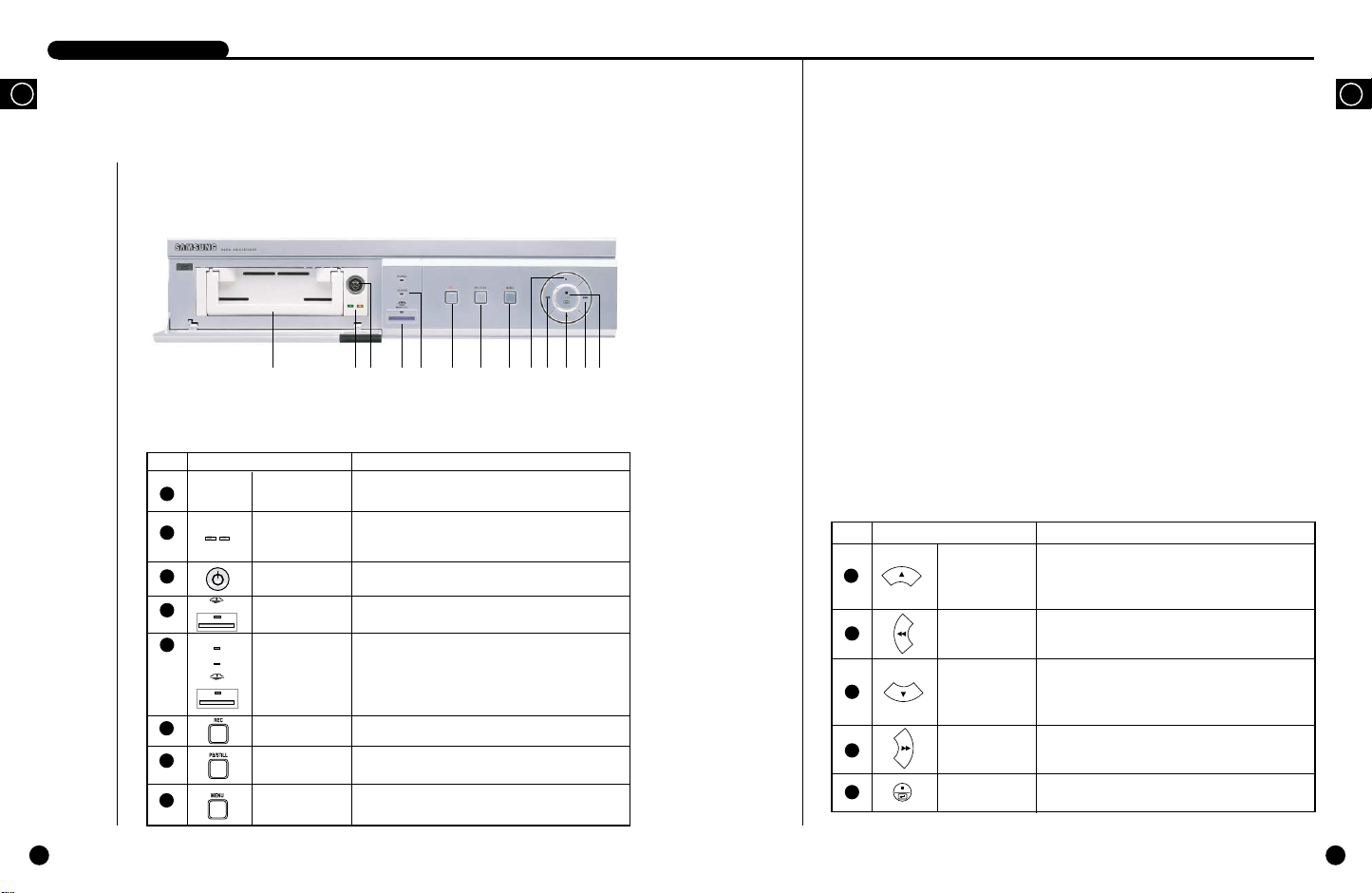
Name and Function of Each Part
3
Front View
! @ # $ % ^ & * ( ) 1 2 3
No Name Function
1
2
3
4
5
Hard Rack
HDD LED
Hard Rack
STICK
MEMORY
STICK
STATUS
DISPLAYLED
6
7
8
REC
PB/STILL
MENU
To install and uninstall of hard disk is available and
you could change the hard disk easily.
LED is an indicator of Hard disk status.
It verifies power supply connection and normal hard
disk access status.
You can lock the Hard disk of Hard Rack.
You can back up the data stored in the system to
MEMORY STICK easily.
Displays system status.
●
●
●
Records current live images.
Plays recorded data.
Pauses screen or shows still screen during play.
Displays the system setup menu or turns menu by
stages.
POWER : Checks power On.
ALARM : Checks Alarm turns operates.
MEMORY STICK : It verifies data copies to
MEMORY STICK.
No Name Function
9
10
11
12
13
UP
LEFT
DOWN
RIGHT
STOP/ENTER
Moves up the cursor in a menu or increases the detailed
setting value for the menu. Shows still cuts in the
forward direction.
Rewinds recorded images during play. Edits or modifies
the left value of a menu for setting up the menu.
Moves down the cursor in a menu or decreases the
detailed setting value for the menu. Shows still cuts one
by one in the backward direction.
Forwards recorded images fast during play or modifies
the right value of a menu for setting up the menu.
To use 'STOP/ENTER' to stop Playing or Recording, it
can be used as ENTER when setting MENU.
GB
1-4
DIGITALVIDEO RECORDER
DIGITALVIDEO RECORDER
GB
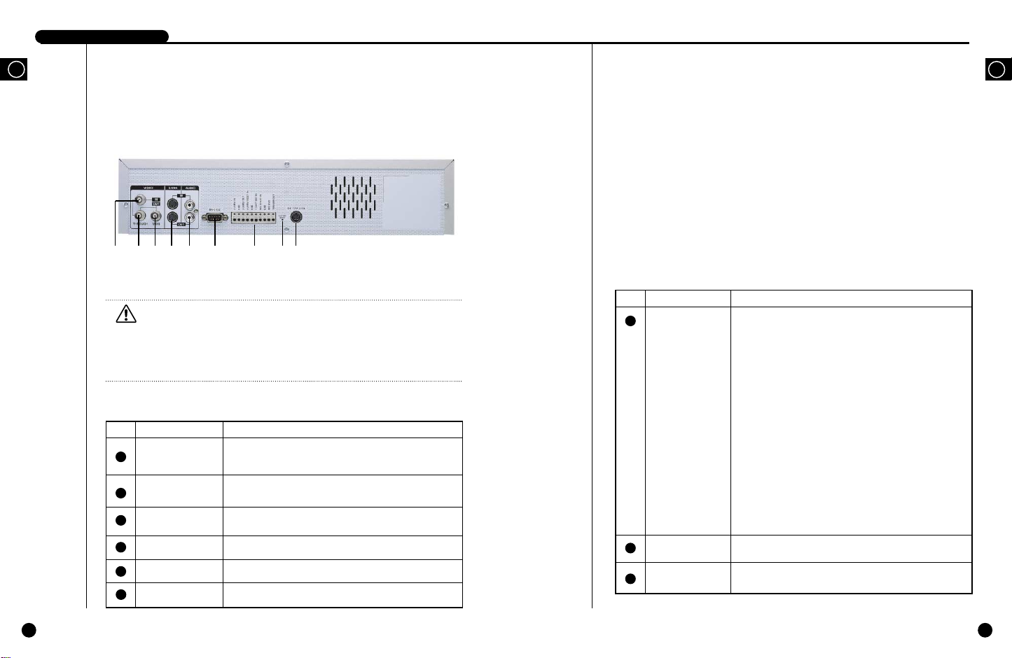
Rear View
! @ # $ % ^ & * (
Caution
Caution
If suffocated, the air inlet or outlet may harm the product performance. Please
install the product where you can secure free ventilation. Never allow goods
around the air inlet or outlet if they are big enough to suffocate it.
If you want to run DVRs on cabinets or Reck, be sure to secure air ventilation.
No Name Function
Image Input Port
1
THROUGH
2
Terminal
3
Image Output Port
It is the composite image signal input port(BNC Style
Connector).
You can use THROUGH Terminal to send VCR signal to
another VCR.
It is a composite image signal input port (BNC Style Connector).
No Name Function
●
External In/Out
7
Port
The system gives an alarm when the High(5V) signal incomes
for more than 0.5 seconds in the N.C.(Normally Closed) mode
and when the Low(0V) signal incomes for more than 0.5 sec
onds in the N.O.(Normally Open) mode.
●
GND
●
ALARM OUT: The High(5V) signal comes out during alarm
recording.
●
ALARM RESET IN : The system cancels the alarm when the
Low(0V) signal incomes for more than 0.5 seconds.
●
1 SHOOT REC IN
●
REC START IN: The system starts recording when the
Low(0V) signal incomes for more than 0.5 seconds.
●
REC END: The Low(0V) signal comes out for about 1 second
when you set the DISK END MODE in the RECORD MODE
SETUP menu to SETUP and the HDD consumes all of its free
space.
●
TRIGGER OUT: This signal converts the Multiplexer record
ing output screen.
GB
1-5
4
S-VHS PORT
5
Voice In/Out Port
6
RS-232 Port
It is the S-VHS image signal in/out port.
It is a voice signal in/out port(RCA Jack).
It is a serial port for remote control.
8
FACTORY RESET
9
POWER
Initializes the system.
Supports the DC power socket.
You can plug in the 100-250 VAC power cord.
1-6
DIGITALVIDEO RECORDER
DIGITALVIDEO RECORDER
GB
4
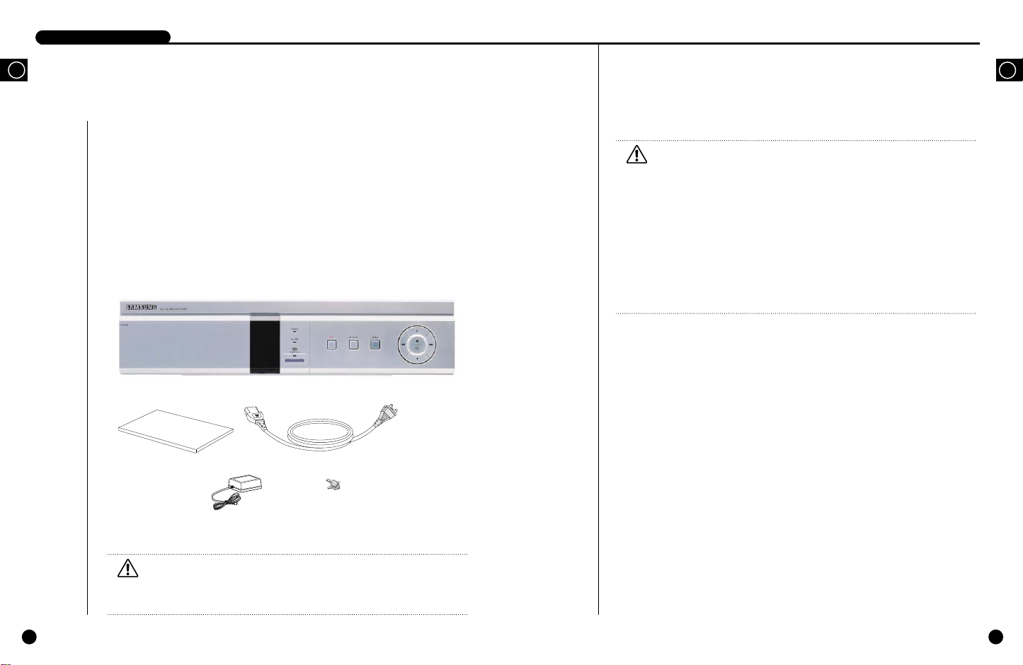
Unpacking
When purchasing product, first remove packing and put it on a flat floor or at a place to use it.
Then, ensure all following contents are included:
◗ Main body
◗ User’s Manual
◗ 1 power cord
◗ 1 Adapter
◗ 2 Hard Rack Locking Keys
SHR-1010
Caution
Caution
Be sure to use the adapter for SHR-1010 only.
Be sure to pay attention to the following when you use the adapter.
1. Use it only in the room.
2. Prevent water or liquid from entering the connector or product.
3. Avoid excessive impact or force.
4. Don't pull the output plug unreasonably.
5. Don't disassemble the product on your own.
6. Abide by the rated input and output range.
7. Use KS power cords only.
8. For the product with an input ground, be sure to use the power cord with a ground.
GB
1-7
Caution
Caution
The above contents can be changed without notice in order to improve the
performance or function of the product.
1-8
DIGITALVIDEO RECORDER
H.D.D.
Lift up
REC
POWER
ALARAM
MEMORY STICK
REC
PB
POWER
ALARAM
MEMORY STICK
H.D.D.
Lift up
H.D.D.
H.D.D.
DIGITALVIDEO RECORDER
GB
5
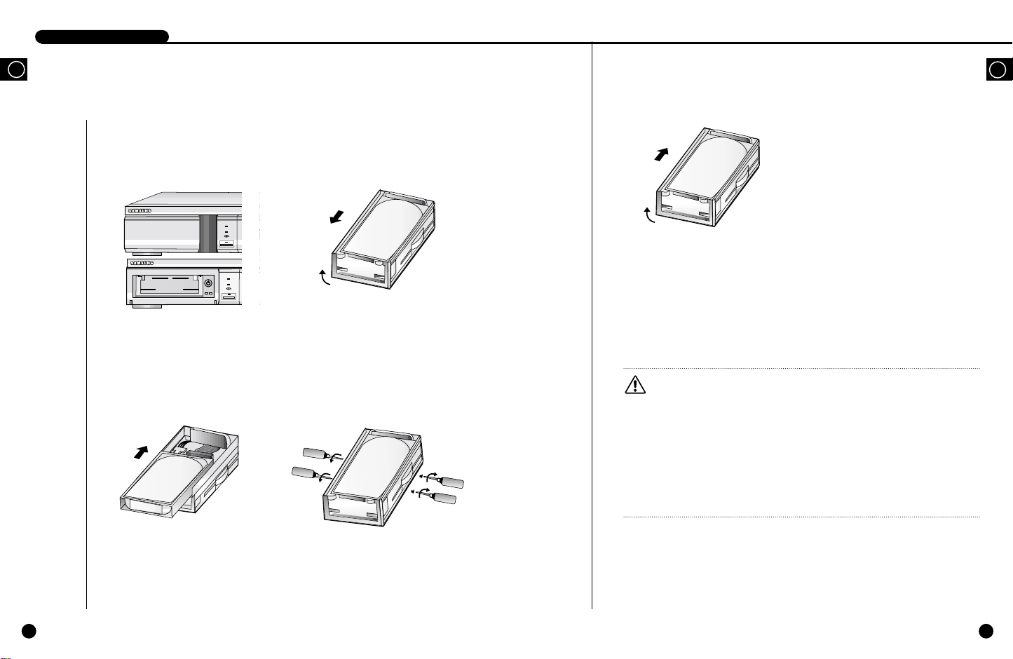
Attaching/Deta ching HDD
Mounting HDD
1. At first, open the Hard Rack cover in
front of Main Deck and then open
Hard Rack using Hard Rack key.
2. Take the hard rack out of the inter
nal rack. Erect the front handle and
pull it down.
5. Erect the front handle of the internal
rack to push it toward the external rack.
After the handle reaches to the end, pull
it down to the bottom for firm fixing.
Caution
Caution
To operate system, you have to lock the key of Hard Rack.
When changing HDD or uninstalling Hard Rack, please make sure that power indicating
LED of HDD is turned off.
Otherwise, the HDD may fall in trouble.
Be sure to format all HDDs before use if they have been used in the other PC.
Otherwise, the system may not operate properly.
We recommended SEC Spinpoint V40 SV4002H or SV8004H for this product.
Please be sure to call the store where you bought the HDD before you want another
one.
6. Lock the hardrack with the key and
turn the power on.
GB
1-9
3. Connect the internal rack data
cable and power cord with the
HDD.
4. Put the HDD in the internal rack and
fix it with a screw.
1-10

GB
II. Connection with Other Devices
2
DIGITALVIDEO RECORDERDIGITALVIDEO RECORDER
DIGITALVIDEO RECORDER
GB
1
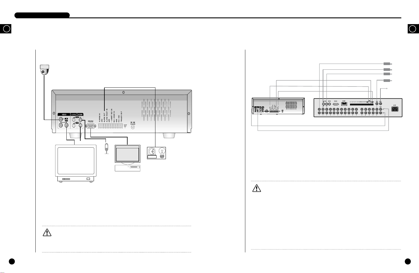
Connection to External Devices
CAMERA
VIDEO OUT
(NTSC/PALMONITOR)
■ This device can be applied to external devices such as image signal input camera, voice
signal input microphone, NTSC for the output of both signals, or PALmonitor.
■ It can be also applied to external devices at user request.
■ It can be applied to PC for serial communication.
Caution
Caution
A CRT monitor capable of displaying an NTSC or PAL video signal must be used with this
unit. An ordinary computer monitor cannot be used.
AUDIO OUT
MICROPHONE
PC
SIREN
LIGHT
Connection with Multiplexer
(e.g. connection to SDM-160)
2
TRIGGER OUT
ALARM IN
GND
SHR-1010 VIDEO RECORDER
VIDEO IN
VIDEO OUT
■ SDM-160 is a Multiplexer for NTSC, and SDM-160Pis a Multiplexer for PAL.
■ For details on the functions of SDM-160, please refer to the user’s guide of SDM-160.
■ Connect this unit’s video signal input jack to the video signal output jack of SDM-160 and
connect this unit’s video signal output jack to the video signal input jack of SDM-160.
■ Connect the alarm output jack (ALARM OUT) of SDM-160 to this unit’s alarm input jack
(ALARM IN), and connect the VTI jack of SDM-160 to this unit’s trigger output jack
(TRIGGER OUT).
■ Connect both GND terminals together.
Caution
Caution
- Be sure to connect the trigger output terminal (TRIGGER OUT) of this unit to the Multiplexer.
Otherwise, a normal recording cannot be made. (For the connection method, please refer to the
user’s guide for the Multiplexer you want to use.)
- If the systemís recording field rate is set to 0.50 ~ 15 FPS (Fields Per Second) for the input NTSC
video signal and to 0.50 ~ 12.5 FPS for the input PAL video signal, be sure to set the Multiplexer in
such a way that the recording output screen is switched by the Trigger Pulse. (For settings related
to the recording field rate, please refer to “(2) PICTURE RATE”on p. 3-12.)
- If the system’s recording filed rate is set to 30 FPS for the input NTSC video signal and to 25 FPS
for the input PAL video signal, a half of the input video channels may not be recorded depending
on the type of Multiplexer. In this case, set the recording field rate to 60 FPS for NTSC and to 50
FPS for PAL.
SDM-160 DIGITALMULTIPLEXER
CAMERA
MONITOR
OUT
GB
1
2
3
.
.
.
16
2-1
2-2
DIGITALVIDEO RECORDER
DIGITALVIDEO RECORDER
GB
3
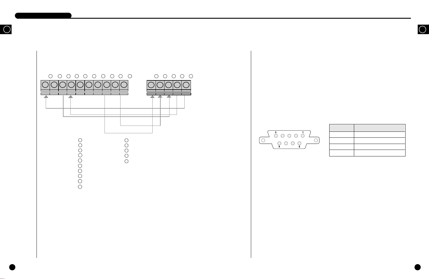
System Connection for Alarm Recording
<Rear Side Connection Terminal of SHR-1010>
1
2 3 4 5 6 7 8 9 10 1 2 3 4 5
1
ALARM IN
2
GND
3
ALARM OUT
4
ALARM RESET IN
5
GND
6
1 SHOT REC IN
7
REC START IN
8
GND
9
REC END
TRIGGER OUT
10
1
GND
2
TRIGGER IN
3
ALARM IN
4
ALARM CANCEL
ALARM OUT
5
<Outside Product>
4
Connection with PC for Use
Connection with RS-232C
You can control the system remotely through the parallel communication of RS-232.
A. Communication Method
● Data Code: ASCII Code
● Data Transmission Method : Start-Stop Asynchronized Serial Interface
● Protocol: 8 bit Data, 1 Stop bit, None Parity
● Transmission speed: 4800, 9600, 19200, 38400 bps
B. RS-232C terminal (D-SUB 9 Pin) and Pin specifications
RS-232 Port behind SHR-1010 System
GB
Pin No Pin Specifications
2 TXD (Transmitted Data)
3 RXD (Received Data)
5 SG (Signal Ground)
1, 4, 6~9 NO Connection
2-3
■ Alarm recording is a function for recording the input video when an alarm signal is input
while a device with alarm output is connected to this unit.
■ Connect to the corresponding terminals, as the numbers may be different for external
devices.
■ For external devices, if the alarm input (ALARM INPUT) and alarm cancel (ALARM
CANCEL) are not available, you can leave them unconnected.
2-4

DIGITALVIDEO RECORDER
GB
C. Code by Key
Start UNIT ID Device Operands Operands
Code (00-99) Class -Type -Code Sum
Menu @
Arrow
LEFT
Arrow
UP
Arrow
DOWN
Arrow
RIGHT
ENTER @
00: DR: FP: 18: N: *
@
@
@
@
00: DR: FP: 24: N: *
00: DR: FP: 25: N: *
00: DR: FP: 26: N: *
00: DR: FP: 27: N: *
00: DR: FP: 28: N: *
Operands
REC @ 00: DR: FP: 29: N: *
STOP @ 00: DR: FP: 30: N: *
PLAYBACK
@ 00: DR: FP: 32: N: *
● The above codes are made up of ASCII CODE values.
● The UNIT ID ranges from 00 to 99 and this ID shall correspond with the ➁ UNIT ID
of the Remote Control Setup menu in Page 3-23.
Ex) When you turn the MENU on with the remote control.
You shall setup the communication environment in the communication program
like HYPER TERMINAL and type in @00:DR:FP:18:N:*. Then the MENU will
pop up.
D. Others
● The above data format and transmission speed is subject to change according to the
future development environment.
● During data transmission, PC will play a role of Master and the system will play a role
of Slave.
● Other orders than input by the above Function keys will not be received. But the
Alarm function is always allowed to receive as long as the relative order was recorded
to the machine. (Due to the late communication speed, there may be some delay.)
Check
2-5

III. Basic Method to use
GB
3

DIGITALVIDEO RECORDERDIGITALVIDEO RECORDER
GB
1
Booting the System
Power On
This system has no power switch.
If you connect the adapter with the power cable,
the LED and button lamps in front of the system
will be turned on and the system will starting
booting with the following message.
After booted, the following live screen will
appear.
Recognizing incoming video signal
The SHR-101A system can automatically recognize whether the image signal connected to the
input port is NTSC or PALsignal when booting the system.
In case you turn on the system with image signal unconnected to the input port, the system will
retrieve the previous image signal of the input terminal and will be initialized accordingly.
For example, if the previous image signal was NTSC , the system will be initialized to fit for
NTSC and if it was PAL, the system will be initialized to fit for PAL.
However, if you connect a signal to the input port which differs from the current input port
signal all of a sudden, the screen will be garbled by lack of recognition. It happens when you
connect PALrather than NTSC as the input signal to the system initialized suitable for NTSC
or the other way around. In either case, you should turn off the system and change the input
signal. Then, you should turn on the system again and it will automatically the image signal
and initialize to fit for it.
If there is no VIDEO signal when you turn on the system
power, VL(Video Loss) is appeared and BUZZER will be
sounded. If you push STOP/ENTER( ) button at
this time, BUZZER will be muted. If you want to make
BUZZER to mute, set VIDEO LOSS BUZZER to OFF at
SYSTEM SETUP menu. Please refer to page 3-18 for
detail.
2001-09-15
07:14:55
2001-09-15
07:14:55
VL
BOOTING...
If you turn the system on without the Hard Rack key
locked, the following message will pop up and the
SHR-1010 system will run improperly though you
installed the HDD.
If you turn the system on without the HDD installed,
the message, 'NO HDD' will pop up and the SHR1010 system will run improperly.
WAITING...
NO HDD
Power Off
Separate the power jack behind the system from the main body.
There is no power switch.
In case you turn off the system during recording, recording will be resumed the next time
when you turn of the system again and booting is complete.
Caution
Caution
Please wait at least three seconds to turn the system on after turn off. If not, system
may work incorrectly.
Factory reset
1. Disconnect system power
2. Push the Reset button located backside of system and hold it, then connect system power again.
3. Push the Reset button until default screen displayed on the monitor.
Caution
Caution
When Factory Reset is implemented, former setting values are initialized to pre-set factory value.
GB
3-1
3-2

DIGITALVIDEO RECORDER
DIGITALVIDEO RECORDER
GB
2
The Basic Screen View
Full Screen View
Here comes the guideline of icons and
descriptions in the normal live screen.
●
2003-02-28
00:00:01
2003-02-28
00:00:01
● When the system is in the recording mode, ●
icon blinks.
● When the system is in the recording mode set
by alarm, icon blinks
● It displays the current date and time for live broadcasting.
● When the system is in the play mode,
❿
If you pauses the play,
velocities. If you play the data in the forward direction at other speed than the normal one,
❿
icon will be replaced with
direction at other speed than the normal one,
Available forward and reverse playing speed of system is forward direction normal, slightly
fast, normal fast and very fast, etc.
● It displays the recorded date and time of the data now in play.
2001-08-22
18:19:12
●
❿
❿
❿
icon takes the place of ¢∫ icon. You can play saved data at various
❿❿❿❿
icon blinks.
icon and if you play the data in the backward
➛
icon will be replaced with
➛➛➛➛
GB
Live Screen Viewing
The normal Live screen looks like this.
2003-01-01
00:00:01
.
● It shows the current date and time as configured by
the system.
2003-01-01
00:00:01
3-3
● When the system is in the recording mode as reserved by the timer, icon blinks.
You can change location of the above system status indicator. Choose the location when
selecting Top Right, Top Left, Bottom Left, Bottom Right and Center. (Select ➅OSD
POSITION and choose T/L, T/R, B/L, B/R, Center of CLOCK/DISPLAY MODE SETUP
menu. Explain it in detail in page 3-11)
3-4

DIGITALVIDEO RECORDER
GB
2003-02-28
00:00:01
❿
Playback screen Viewing
The normal Playback screen looks like this.
● It shows the recorded date and time of the data
currently being played back.
● While the system is in the play mode, the
remains in the screen but the icon will take the
place of the icon when the system is temporarily
paused.
You can also play the HDD data at various speeds.
If the system plays the HDD data at other speed
than the default in the forward or backward
direction, the
the
Available forward and reverse playing speed of
system is forward direction normal, slightly fast,
normal fast and very fast, etc.
❿❿❿❿
❿
or ➛icon will be replaced with
or
➛➛➛➛
icon respectively.
❿
icon
2003-01-01
00:00:01
❿
3
Menu View
Menu Enter
Note
Note
You can go into the menu only when the system is in the Live screen mode. If the
system is in the recording mode or playback mode, you cannot go into the menu.
To go into the menu, first stop the recording or playback.
Menu Move
MAIN MENU
CLOCK/DISPLAY MODE SETUP
RECORD MODE SETUP
ALARM RECORD SETUP
Press a MENU( ) button. Then, following screen
appears.
Move to desired menu item by using an UP ( ) or a DOWN( ) button. In this case, a
highlighted cursor is displayed in the selected item. The sub menu item is displayed if pressing
a STOP/ENTER( ) button. Selections appear in the left side and settings for selected
matters appear in the right side.
TIMER RECORD SETUP
SYSTEM SETUP
IMAGE SETUP
SYSTEM INFORMATION
❷
:MENU :SELECT MENU:EXIT
GB
3-5
3-6

DIGITALVIDEO RECORDER
DIGITALVIDEO RECORDER
GB
Change of Settings
① Move to desired menu item by using an UP( ) or a DOWN( ) button.
➁ You can change settings by pressing the STOP/ENTER( ) button.
➂ Press the UP( ) or DOWN( ) button in order to change settings.
➃ Settings will be changed if pressing the STOP/ENTER( ) button after selecting
desired settings.
Move to Parent Menu or Menu End
Press the MENU button to move to the parent menu from the lower mode or end the menu.
Example of menu setting (in case of changing time)
① Press the MENU button and then press the
STOP/ENTER( ) button when the cursor
points out the CLOCK/DISPLAYMODE
SETUP. Then following screen appears.
➁ Press the DOWN( ) button so the cursor
points out TIME.
Then if pressing the STOP/ENTER( )
button, the cursor is changed so hour may be
changed.
➂ Press the UP( ) or DOWN( ) button
so current time (hour) is displayed.
Then if pressing the RIGHT( ) button,
the cursor is changed so minute may be
changed.
CLOCK/DISPLAY MODE SETUP
DATE 2003-01-01
TIME 00:00:01
DATE DISPLAY TYPE YYYY-MM-DD
DATE & TIME DISPLAY ON
STATUS DISPLAY ON
STATUS POSITION T/L
LANGUAGE ENGLISH
❷
:MOVE :SELECT MENU:EXIT
CLOCK/DISPLAY MODE SETUP
DATE 2003-01-01
TIME 00:00:01
DATE DISPLAY TYPE YYYY-MM-DD
DATE & TIME DISPLAY ON
STATUS DISPLAY ON
STATUS POSITION T/L
LANGUAGE ENGLISH
❷
:CHANGE ➛❿:MOVE :SET MENU:CANCEL
CLOCK/DISPLAY MODE SETUP
DATE 2003-01-01
TIME 00:00:00
DATE DISPLAY TYPE YYYY-MM-DD
DATE & TIME DISPLAY ON
STATUS DISPLAY ON
STATUS POSITION T/L
LANGUAGE ENGLISH
❷
:CHANGE ➛❿:MOVE :SET MENU:CANCEL
GB
3-7
3-8

DIGITALVIDEO RECORDER
GB
➃ Similarly, press the UP( ) or DOWN
( ) button so current minute is displayed.
Then if pressing the LEFT( ) or RIGHT
( ) button, the cursor is changed so hour
or second is changed. For example, press the
RIGHT( ) button to change seconds and
setup by pressing the UP( ) or DOWN
( ) button so current second is displayed.
➄ The cursor is changed as follows if pressing
the STOP/ENTER( ) button after setting
all hours. You may change other settings by
pressing the UP( ) or DOWN( )
button.
CLOCK/DISPLAY MODE SETUP
DATE 2001-12-07
TIME 09:34:00
DATE DISPLAY TYPE YYYY-MM-DD
DATE & TIME DISPLAY ON
STATUS DISPLAY ON
STATUS POSITION T/L
LANGUAGE ENGLISH
❷
:CHANGE ➛❿:MOVE :SET MENU:CANCEL
CLOCK/DISPLAY MODE SETUP
DATE 2001-12-07
TIME 09:34:27
DATE DISPLAY TYPE YYYY-MM-DD
DATE & TIME DISPLAY ON
STATUS DISPLAY ON
STATUS POSITION T/L
LANGUAGE ENGLISH
❷
:MOVE :SELECT MENU:EXIT
Each menu item
! CLOCK/DISPLAY MODE SETUP % SYSTEM SETUP
CLOCK/DISPLAY MODE SETUP
DATE 2003-01-01
TIME 00:00:00
DATE DISPLAY TYPE YYYY-MM-DD
DATE & TIME DISPLAY ON
STATUS DISPLAY ON
OSD POSITION T/L
LANGUAGE ENGLISH
❷
:MOVE :SELECT MENU:EXIT
@ RECORD MODE SETUP ^ IMAGE COPY
RECORD MODE SETUP
PICTURE QUALITY HIGH
PICTURE RATE 30.00FPS
DISK END MODE CONTINUE
DISK END BUZZER OFF
❷
:MOVE :SELECT MENU:EXIT
# ALARM RECORD SETUP & REMOTE CONTROL SETUP
ALARM RECORD SETUP
ALARM ENABLE OFF
ALARM DETECT TYPE NC
ALARM BUZZER OFF
MAIN ALARM TIME 10 sec
MAIN ALARM PICTURE RATE
❷
:MOVE :SELECT MENU:EXIT
30.00FPS
$ TIMER RECORD SETUP * SYSTEM INFORMATION
TIMER RECORD SETUP
TIMER DAY START END
01 OFF OFF --:-- --:-02 OFF OFF --:-- --:-03 OFF OFF --:-- --:-04 OFF OFF --:-- --:-05 OFF OFF --:-- --:-06 OFF OFF --:-- --:--
❷
➛❿
:MOVE :SELECT MENU:EXIT
CLOCK/DISPLAY MODE SETUP
PASSWORD ********
PASSWORD LOCK OFF
CLEAR ALL DATA OFF
DEFAULT SETUP OFF
VIDEO INPUT PORT COMPOSITE
VIDEO SOURCE
VIDEO LOSS BUZZER ON
❷
:MOVE :SELECT MENU:EXIT
IMAGE COPY
REC FROM 2003-04-07 12:47:07
REC TO 2003-04-08 10:46:26
FROM 2003-04-07 20:41:12
TO 2003-04-07 20:42:12
COPY ON MEMORY STICK
DELETE ALL
❷
:MOVE :SELECT MENU:EXIT
REMOTE CONTROL SETUP
REMOTE CONT OFF
UNIT ID 0
BAUD RATE 9600
DATA BIT 8
STOP BIT 1
PARITY None
❷
:MOVE :SELECT MENU:EXIT
SYSTEM INFORMATION
CAPACITY(GB) 39.79
VERSION 1.00
SYSTEM LOG
:SELECT MENU:EXIT
MULTIPLEXER
GB
3-9
Note
Note
All the menu values are supposed to be set to the basic one as shown above at
the time of factory shipment.
3-10

DIGITALVIDEO RECORDER
DIGITALVIDEO RECORDER
GB
3-11
Setting of Date, Time and Screen
4
The following illustrates the intial setting of the CLOCK/DISPLAYMODE SETUP menu.
① DATE
Set the current date.
② TIME
Time can be entered in the form of 24 hours.
Caution
Caution
When change date or time, if the time is
overlapped with already stored recording data
time, following message meaning deletion of
former stored data, is appeared.
If you choose YES, system re-booting is
implemented. Be sure to set the date and time
to the current date and time.
➂ DATE DISPLAYTYPE
There are 3 date forms to be displayed. You can set in a convenient manner to see.
[YYYY-MM-DD/DD-MM-YYYY/MM-DD-YYYY]
➃ DATE & TIME DISPLAY
Set to ON to display the date and time on the screen, or set to OFF to not display them.
[ON/OFF]
➄ STATUS DISPLAY
Set to ON to display the system status, such as recording, and playback information when
playing the recorded video; or set to OFF to not display them. [ON/OFF]
➅ OSD POSITION (System Process Mark Position)
It determines where the system process mark will be displayed on the screen.
Each symbol indicates different positions, TL for the top left, TR for the top right, BL for
the bottom left, and BR for the bottom right. When setting to Center, it is displayed in the
center of screen. [TL/TR/BL/BR/CENTER]
⑦ LANGUAGE ENGLISH (Language Selection Function)
Select an OSD language to be displayed on the screen.
You can choose a language among English, Spanish, Italian, German, and French.
If you select a language and hit , it will be selected.
[ENGLISH/ESPANOL/ITALIANO/DEUTSCH/FRANCAIS]
CLOCK/DISPLAY MODE SETUP
DATE 2003-01-01
TIME 00:00:00
DATE DISPLAY TYPE YYYY-MM-DD
DATE & TIME DISPLAY ON
STATUS DISPLAY ON
OSD POSITION T/L
LANGUAGE ENGLISH
❷
:MOVE :SELECT MENU:EXIT
CHANGING TIME INTO THE PAST
CAUSES DELETION OF THE ORIGINAL DATA
CORRESPONDING TO OVERLAPPING TIME!
PROCEED?
YES
NO
5
Record Setup
The following illustrates the intial setting of the RECORD MODE SETUP menu.
Note
Note
Voice will be recorded at the speed of 24 Kbps irrespective of image recording
picture rate. But, the audio data can not be recorded as long as the PICTURE RATE is
set to below 10.00FPS for NTSC and below 8.33FPS for PAL respectively. For
recording the audio data, please set the PICTURE RATE to above 15.00FPS for NTSC
and above 12.50FPS for PAL respectively.
① PICTURE QUALITY
② PICTURE RATE
RECORD MODE SETUP
PICTURE QUALITY HIGH
PICTURE RATE 30.00FPS
DISK END MODE CONTINUE
DISK END BUZZER OFF
❷
:MOVE :SELECT MENU:EXIT
Picture quality is divided into four levels. Set to VERY HIGH for the best picture quality,
or set to HIGH, STANDARD, or LOW in the descending order of qualty. The user can
select the desired quality.
[VERY HIGH/HIGH/STANDARD/LOW]
Set the picture rate for the input video. If the input video signal is NTSC, a maximum of
30 FPS (Fields Per Second) can be recorded; if it is PAL, a maximum of 25 FPS can be
recorded. However, when recording with ‘Very High’setting, you could record 15.00 FPS
max for NTSC and 12.50 FPS max for PAL.
1) NTSC
[30.00FPS/15.00FPS/10.00FPS/7.50FPS/5.00FPS/2.50FPS/1.00FPS/0.50FPS]
2) PAL
[25.00FPS/12.50FPS/8.33FPS/6.25FPS/5.00FPS/2.50FPS/1.00FPS/0.50FPS]
GB
3-12

DIGITALVIDEO RECORDER
DIGITALVIDEO RECORDER
GB
Note
Note
The following table shows how long it takes to fill up 40GB and 80GB HDD for each field
rate when the image signal is NTSC and PAL respectively.
(The recording time for each field rate may slightly vary depending on the type of input
image signal.)
Time-Lapse Mode
Picture Rate
NTSC
PAL
30.00 FPS - - 18.5 hr 37.0 hr 24.7 hr 49.4 hr 37.0 hr 74.1 hr
15.00 FPS 18.5 hr 37.0 hr 30.9 hr 61.7 hr 49.4 hr 98.8 hr 74.1 hr 148.1 hr
10.00 FPS 27.8 hr 55.6 hr 46.3 hr 92.6 hr 74.1 hr 148.1 hr 111.1 hr 222.2 hr
7.50 FPS 37.0 hr 74.1 hr 61.7 hr 123.5 hr 98.8 hr 197.5 hr 148.1 hr 296.3 hr
5.00 FPS 55.6 hr 111.1 hr 92.6 hr 185.2 hr 148.1 hr 296.3 hr 222.2 hr 444.4 hr
2.50 FPS 111.1 hr 222.2 hr 185.2 hr 370.4 hr 296.3 hr 592.6 hr 444.4 hr 888.9 hr
1.00 FPS 277.8 hr 555.6 hr 463.0 hr 925.9 hr 740.7 hr 1481.5 hr 1111.1 hr 2222.2 hr
0.50 FPS 555.6 hr 1111.1 hr 925.9 hr 1851.9 hr 1481.5 hr 2963.0 hr 2222.2 hr 4444.4 hr
25.00 FPS - - 18.5 hr 37.0 hr 29.6 hr 49.4 hr 37.0 hr 74.1 hr
12.50 FPS 18.5 hr 37.0 hr 30.9 hr 61.7 hr 59.3 hr 98.8 hr 74.1 hr 148.1 hr
8.33 FPS 27.8 hr 55.6 hr 46.3 hr 92.6 hr 88.9 hr 148.2 hr 111.2 hr 222.3 hr
6.25 FPS 37.0 hr 74.1 hr 61.7 hr 123.5 hr 118.5 hr 197.5 hr 148.1 hr 296.3 hr
5.00 FPS 46.3 hr 92.6 hr 77.2 hr 154.3 hr 148.1 hr 246.9 hr 185.2 hr 370.4 hr
2.50 FPS 92.6 hr 185.2 hr 154.3 hr 308.6 hr 296.3 hr 493.8 hr 370.4 hr 740.7 hr
1.00 FPS 231.5 hr 463.0 hr 385.8 hr 771.6 hr 740.7 hr 1234.6 hr 925.9 hr 1851.9 hr
0.50 FPS 463.0 hr 925.9 hr 771.6 hr 1543.2 hr 1481.5 hr 2469.1 hr 1851.9 hr 3703.7 hr
Very High High Standard Low
40GB 80GB 40GB 80GB 40GB 80GB 40GB 80GB
➂ DISK END MODE (In case of no margin in the HDD space)
Note If you set the DISK END mode to STOP, the HDD free space capacity will be
Note
displayed but if you set the mode to CONTINUE, such capacity will not be
displayed.
RECORD MODE SETUP
PICTURE QUALITY HIGH
PICTURE RATE 30.00FPS
DISK END MODE STOP
DISK END BUZZER OFF
HDD FREE SPACE : 99%
❷
:MOVE :SELECT MENU:EXIT
➃ DISK END BUZZER
It will be activated when you set the DISK END mode to STOP to enable setup.
If set to ON, the Buzzer will sound when the HDD is full during the recording; if set to
OFF, the Buzzer will not sound. [ON/OFF]
GB
3-13
- If you set to STOP, the system will pause recording
when the HDD is full of data and the message,
“HDD FULL” will pop up.
- If you set it to CONTINUE, recording is kept on
overwriting current recording data to
former recorded data. Overwriting is started from the
old section of stored data.
2003-01-12
13:43:42
HDD FULL!
3-14

DIGITALVIDEO RECORDER
DIGITALVIDEO RECORDER
GB
6
Alarm Record Setup
The following illustrates the intial setting of the ALARM RECORD SETUP menu.
① ALARM ENABLE
To set whether to start recording or not when alarm
go off. If you want to start recording when alarming,
set it ON, if not set it OFF. If you exit the menu after
setting ON for ALARM ENABLE, system starts
recording whenever alarm go off. To stop the
recording started by alarm intentionally, push the
STOP/ENTER( ) button.[ON/OFF]
② ALARM DETECT TYPE
Set to N. C. (Normally Close) when the alarm input is Active High, and set to N.O.(Normally
Open) when the alarm input is Active Low. [N.C./N.O.]
➂ ALARM BUZZER
Set to ON to have the system activate the Buzzer when a motion is deteced in the input
video or when alarm occurs, or set to OFF to keep the Buzzer inactive. [ON/OFF]
➃ ALARM TIME
It determines the time of alarm recording from 10 second (OFF) to 5 minutes when the system
detects any movement or alarm in the input image.
If you set it to AUTO, alarm recording will be implemented during the alarm-generating
signal is in active state.
[5MINUTE/4MINUTE/3MINUTE/2MINUTE/1MINUTE/30SECOND/20SECOND/
10SECOND/AUTO]
ALARM RECORD SETUP
ALARM ENABLE OFF
ALARM DETECT TYPE NC
ALARM BUZZER OFF
ALARM TIME 10 sec
ALARM PICTURE RATE
❷
:MOVE :SELECT MENU:EXIT
30.00FPS
Reservation Record Setup
7
The following illustrates the intial setting of the TIMER RECORD SETUP menu.
● Reservation Recording function is a function
which enables recording automatically when you
are not at home, you could set the system to
implement recording at desired day of the week,
desired time duration. At first, locating cursor to
the timer column with OFF and set it to ON,
then select desired day of the week at DAY
column, after that input recording start time and
end time to start and end column respectively.
If you set DAYto SUN~SAT,Reservation
Recording set up items will be applied to designated day only, If you set ALL, Reservation
Recording set up items will be applied to all day of the week. And, if you set M~F,
Reservation Recording set up items will be applied just to Monday through Friday.
If you setup the RESERVE RECORDING and escape from the MENU, the icon
indicating RESERVE RECORDING was successfully reserved will pop up. Then the
will pop up at the reserved time while recording begins. To stop recording intentionally,
push the STOP/ENTER( ) button. Thus, the recording is stopped. Available numbers
of Reservation Recording are up to by 24. PICTURE RATE determines FIELD RATE of
Reservation Recording, at that time of Reservation Recording start.
TIMER RECORD SETUP
TIMER DAY START END
01 OFF OFF --:-- --:-02 OFF OFF --:-- --:-03 OFF OFF --:-- --:-04 OFF OFF --:-- --:-05 OFF OFF --:-- --:-06 OFF OFF --:-- --:--
❷
➛❿
:MOVE :SELECT MENU:EXIT
● icon
GB
3-15
➄ ALARM PICTURE RATE
It sets the main alarm recording field rate. In case of NTSC as the input image signal, up to
30 FPS can be recorded and in case of PAL, up to 25 FPS can be recorded.
But, in case of recording after setting PICTURE QUALITY to VERY HIGH, you could
record 15.00 FPS max for NTSC and 12.50 FPS max for PAL.
1) NTSC
[30.00FPS/15.00FPS/10.00FPS/7.50FPS/5.00FPS/2.50FPS/1.00FPS/0.50FPS]
2) PAL
[25.00FPS/12.50FPS/8.33FPS/6.25FPS/5.00FPS/2.50FPS/1.00FPS/0.50FPS]
3-16

DIGITALVIDEO RECORDER
DIGITALVIDEO RECORDER
GB
System Setup
8
The following illustrates the intial setting of the SYSTEM SETUP menu.
① PASSWORD
Setting password of system. You can input a
password from 4 characters to 8 characters, initial
setting value is Left( ), Right( ), Up( )
and Down( ) of direction key.
Caution
Caution
In case you forget your password, please reset the factory and the password will return
to the initial default value.
Please refer to Page 3-2, FACTORY RESET for the detailed factory resetting method.
② PASSWORD LOCK
If you set this to ON, you can ask for a password, which is set in the PASSWORD, each
time the MENU button is pressed or the recording lock cancellation is attempted during the
recording, and stop the respective operation if wrong password is entered. If set to OFF, you
do not have to enter password for each case metioned above. [ON/OFF]
➂ CLEAR ALLDATA(Deleting all HDD data)
If you set this to ON and terminate the menu, the
system will delete all the data of the HDD.
[ON/OFF]
Then, if you press the MENU key to return to the
MENU, the system will confirm again as follows. If
you set this to YES and input the password, all data
will be deleted.
CLOCK/DISPLAY MODE SETUP
PASSWORD ********
PASSWORD LOCK OFF
CLEAR ALL DATA OFF
DEFAULT SETUP OFF
VIDEO INPUT PORT Composite
VIDEO SOURCE
VIDEO LOSS BUZZER ON
❷
:MOVE :SELECT MENU:EXIT
CLEAR ALL DATA
This operation will clear all
recorde data. System must restart
to complete this operation
Continue?
YES
NO
MULTIPLEXER
Caution
Caution
Once deleted, the data can not be retrieved for ever. Please check again before you
press the CLEAR ALL DATA.
➃ DEFAULT SETUP (Resetting the system to the initial status at the time of
factory shipment)
If you set this to ON and terminate the menu, all
the setting data will return to the original ones
that the system had just out of the factory.
Despite, the HDD data will be left intact.
[ON/OFF]
Then, if you press the MENU key to return to the
MENU, the system will confirm again as follows.
If you set this to YES and input the password, all
the setting value will be deleted.
LOAD DEFAULT SETUP
Do you want to reload default
settings
YES
NO
⑤ VIDEO INPUT PORT(INPUT selection)
Input supports Composite video input having BNC terminal.
Also, it is possible to select S-VHS input. [COMPOSITE/S-VHS]
➅ VIDEO SOURCE
It supports coupling with MULTIPLEXER.
In case of 1 channel, it can be selected and used to CAMERA.
[MULTIPLEXER/CAMERA]
⑦ VIDEO LOSS BUZZER
You can turn the BUZZER ON or OFF when encountering Video input signal LOSS.
[ON/OFF]
GB
3-17
3-18

DIGITALVIDEO RECORDER
GB
Image Copy & Play Setup
9
The IMAGE COPY has the following menu items.
The IMAGE COPY copy or play recorded images
through the MEMORY STICK.
Put the cursor in the FROM row and press the
ENTER button ( )
① REC FROM
Recording start time for the very first data
stored in HDD
② REC TO
Recording end time for the very last data stored in HDD
➂ FROM
The beginning of the image for IMAGE COPY Set the year/month/day/hour/minute/
second of the FROM.
➃ TO
The end of the image for IMAGE COPY Set the year/month/day/hour/minute/second of
the END.
➄ COPY ON MEMORY STICK
Selected block for IMAGE COPY Select the COPY ON MEMORY STICK.
Then, IMAGE COPY will start with the following messages.
< IMAGE COPY Procedure >
- Searching copy : Searches the MEMORY STICK Device.
- Searching image data : Searches the image data to be copied.
- Preparing copy : Prepares IMAGE COPY.
- COPYING............. ( 0% ~100% ) : Displays the progress ratio from 0% to
- Closing copy device : Terminates IMAGE COPY.
- Copy is completed : Compiles the copied image into an execu
Caution
Caution
You should press the MENU(MENU) to return to the MENU after you see the
message "Copy is completed". Then, you should take out the MEMORY STICK to
prevent data from being damaged during play
100%.
tion file.
IMAGE COPY
FROM 2003-01-01 00:00:01
TO 2003-01-01 00:00:01
PROGRESS
COPY ON MEMORY STICK
DELETE ALL
❷
:MOVE :SELECT MENU:EXIT
When implementing copy without
MEMORY STICK, following messages are
appeared.
If you choose OK, Copy Device is not
available message is appeared.
Also, in case of capacity of MEMORY
STICK is less than the size of copy-wished
data, a message Not enough space on copy
device meaning storage space of storage
device is not enough, is appeared. In this
case, you should reduce the time of copying
or exchange the MEMORY STICK having
larger capacity.
➅ DELETE ALL
Delete all copied images.
Confirmation message is appeared asking to
delete the data in MEMORY STICK as
below.
If you choose YES, Files are deleted
message, which means deletion of the data
in MEMORY stick, is appeared.
No media!
OK
IMAGE COPY
REC FROM 2003-04-07 12:47:07
REC TO 2003-04-08 10:46:26
FROM 2003-04-07 20:41:12
TO 2003-04-07 20:42:12
COPY ON MEMORY STICK
DELETE ALL
Copy device is not available
❷
:MOVE :SELECT MENU:EXIT
IMAGE COPY
REC FROM 2003-04-07 12:47:07
REC TO 2003-04-08 10:46:26
FROM 2003-04-07 20:41:12
TO 2003-04-07 20:42:12
COPY ON MEMORY STICK
DELETE ALL
Not enough space on copy device
❷
:MOVE :SELECT MENU:EXIT
This will delete all files in the
media. Proceed?
YES
NO
IMAGE COPY
REC FROM 2003-04-07 12:47:07
REC TO 2003-04-08 10:46:26
FROM 2003-04-07 20:41:12
TO 2003-04-07 20:42:12
COPY ON MEMORY STICK
DELETE ALL
Files are deleted
❷
:MOVE :SELECT MENU:EXIT
GB
3-19
3-20

DIGITALVIDEO RECORDER
GB
Caution
Caution
Please be careful because all stored data are deleted at once.
Copied image can be played as below.
Separate the MEMORY STICK from SHR-1010.
(* You should press the MENU( ) to return to the MENU after you see the
message "Copy is completed". Then, you should take out the MEMORY
STICK to prevent data from being damaged during the play.)
Insert the image-copied memory stick into the PC-connected memory stick reader.
Double click the image-copied files to execute the following programs.
You don’t need to install any kind of program to look at copied image file.
The player program is included in the copted image.
Caution
Caution
Please use 8MB~128MB as a memory stick for image copy.
- PRINT
You may print out the screen during replay or being paused.
-
SAVE
You can capture and save the screen during replay or being paused. Press the SAVE button,
determine the position and name of the file to be saved. All data will be saved in bmp files.
-
RECORD
Displays the start and finish time of data backup.
-
ENCRYPTION
Indicates if the copied data has been modulated from the data stored in the system. If it
reads WRONG, the copied data has been modulated.
-
TIME
Indicates the time of the data in current replay.
-
IMAGE SEARCH SLIDE BAR
Indicates the position of the data in current replay with reference to the whole data.
-
PLAYBACK FUNCTION BUTTON
You can handle all the data play functions including PLAY, REVERSE, PAUSE, FF, and
FR. You can also see frame by frame and go to either the beginning or end.
-
BRIGHTNESS CONTROL SLIDE BAR
You can control the screen brightness. If you press the REFRESH button by the slide bar,
the brightness will return to the initial default.
-
OSD BUTTON
Displays the screen OSD informatin during replay or pause. Every time you press this
button, it will display and hide the TIME information in turn.
GB
3-21
3-22

DIGITALVIDEO RECORDER
GB
10
Communication Setup
Here comes the initial setup procedure of the REMOTE CONTROL SETUP menu.
① Set the REMOTE CONT to ON. [ON/OFF]
② Set up the UNIT ID. [0~99]
➂ Set up the data transmission speed for the
RS-232C communication at the BAUD RATE
(data transmission speed).
[300/600/1,200/2,400/4,800/9,600/19,200/
38,400/57,600/115,200]
➃ Set up the DATA BIT. [7/8]
➄ Set up the STOPBIT. [1/2]
➅ Set up the PARITY. [NONE/ODD/EVEN]
REMOTE CONTROL SETUP
REMOTE CONT OFF
UNIT ID 0
BAUD RATE 9600
DATA BIT 8
STOP BIT 1
PARITY None
❷
:MOVE :SELECT MENU:EXIT
11
System Information
Here comes the initial setup procedure of the SYSTEM INFORMATION menu.
● It reveals the basic system information.
The CAPACITY(GB) displays the whole HDD
space(GB : Giga Byte).
The VERSION displays the software version of the
system.
SYSTEM LOG shows all of the system motions in
the order of date and time.
SYSTEM INFORMATION
CAPACITY(GB) 39.79
VERSION 1.00
SYSTEM LOG
:SELECT MENU:EXIT
SYSTEM LOG
Page 1/42
2001-09-24 00:00:52 Setup Begin
2001-09-24 00:07:38 Playback End
2001-09-24 00:11:56 Playback Begin
2001-09-24 00:23:24 Playback End
2001-09-24 00:39:12 Playback Begin
2001-09-24 01:47:06 Playback End
2001-09-24 02:52:10 Playback Begin
2001-09-24 02:55:37 Playback End
❷
:MOVE MENU:EXIT
3-23
3-24

IV. Record
GB
4

DIGITALVIDEO RECORDER
GB
1
Basic Record
Basic Record
① CURRENT IMAGE RECORD
Press the RECORD( ) button to record
current image. If doing so, the light of the
RECORD( ) button turns on and record
starts while following message appears on the
screen. Settings related with record are done in
the RECORD MODE SETUP menu.
Note
Note
The system does not support recording in the PLAYBACK screen.
- When you stays in the menu, you can not record if you press the RECORD button( ).
- Consequently, you should get out of the menu before recording.
Recording stops when image signal supply is suspended.
But if the image signal supply resumes later, the system will recognize immediately and start
recording again.
Nevertheless, the system will take no action for recording if you don't transmit any image
signal to the input port and press the RECORD button( ).
2003-01-01
00:00:01
●
② Recording Stop
Please press the STOP button ( ) to
stop recording.
Then, the RECORD button( ) lamp is
out, the screen will enter the LIVE mode and
the recording will be paused.
Note
Note
Pressing the menu button during recording will not help to show the menu screen.
To view the menu screen, please stop recording.
2003-01-01
00:00:01
GB
4-1
4-2

DIGITALVIDEO RECORDER
GB
2
Recording Alarm
Recording Alarm
You will see the alarm input port(ALARM IN) in
the external in/out port behind the SHR-1010
system.
You should connect ALARM IN to the alarm
output port of external products like Multiplexer.
(For the details, please refer to p.2~3
"3. System Connection for Alarm Recording".)
Now, you should set theALARM ENABLE in
the ALARM RECORD SETUP menu to ON.
Once recording starts, the following message appears on the screen to instruct alarm
recording is in action.
Release of Alarm Record
If the system is not in the alarm recording mode, in order to cancel the alarm recording
mode, set the ALARM ENABLE and MOTION DETECTION of the ALARM
RECORD SETUP menu to OFF. When you push the STOP button in alarm activating
state, Alarm( ) icon is disappeared. If you push the STOPbutton once more at this
time, REC(
) is stopped.
2003-01-01
00:00:01
●
Reservation Record
3
Reservation Record Setup
You can enter the day, time for the timer recording in the TIMER RECORD SETUP menu
so that the recording will be made on the set day for the set amount of time.
Reservation Record Cancel
If the system is not in the timer recording mode, in order to cancel the timer recording, set
the TIMER row of the line you want to cancel to OFF in one of the timer recording list set
in the TIMER RECORD SETUP menu.
However, to stop recording implemented by Reservation Recording intentionally, push the
STOP/ENTER( ) button, then the recording is stopped. To stop recording completely,
enter the Reservation Recording menu and set the appropriate TIMER item to OFF.
GB
4-3
4-4

V. Retrieval and Playback
GB
5

DIGITALVIDEO RECORDER
GB
1
Retrieval Menu View
Retrieval Menu Enter
Press the MENU button( ) for searching the
data recorded at the state of playing.
If doing so, following screen appears.
Note
Note
- Recorded data Search is available only in the play mode
- If in in the playback mode, when you try to search the recorded data to play back, a
newly searched data is played back regardless of which data has previosly been played
back.
- While the user is in the menu, pressing the SEARCH button will not take you to the
search menu. To go into the search menu, first exit the menu.
Menu Move
Use the UP( ) or DOWN( ) button to move to the desired menu item. At this time,
a highlighted cursor is shown by the selected item. Then, press the STOP/ENTER
( ) button to go into a sub-menu. In the sub-menu, you can enter enquiries for data
search or select and play back the desired data from the list of recorded data.
SEARCH MENU
DATE & TIME SEARCH
ALARM EVENT SEARCH
❷
:MOVE :ENTER MENU:EXIT
Upper Menu Move and Menu End
Press the MENU button to move from the lower menu to the upper menu or end menu.
Each Menu Item
① CLOCK/DISPLAY MODE SETUP ② ALARM EVENT SEARCH
DATE/TIME SEARCH
RECORD FROM 2003-01-01 09:22:31
TO 2003-01-30 15:33:23
GO TO 2003-01-14 13:42:26
❷
:CHANGE ➛❿:MOVE :GO MENU:CANCEL
Caution
Caution
- When you go into the DATE & TIME SEARCH menu, the current date and time
will be displayed by the DATE and TIME fields. Enter the desired date and time to
search the recorded data.
- As the system contains no data in the HDD at factory shipment, you are not able
to view the list in the ALARM EVENT SEARCH menu.
ALARM EVENT SEARCH
EVENT NO. 3/3
2001-05-11 09:23:55 AI
2001-05-14 15:22:13 AI
2001-05-14 15:30:00 AI
❷
➛❿:MOVE :SELECT MENU:EXIT
GB
5-1
Retrieval Condition Enter and List Item Select
In the DATE & TIME SEARCH or ALARM EVENT SEARCH menu, you can input
conditions for data searching and select it. The method of inputting search condition or
selecting one from the list is the same as general menu.
5-2

DIGITALVIDEO RECORDER
GB
2
Date and Time Search
GO TO :
Press the LEFT or RIGHT button ( / ) until
you reach the year/month/day/hour/minute/second for
search and press the UP or DOWN button ( / )
until you reach the year/month/day/hour/minute/second
for setup.
Press the ENTER button ( ) to move to the part
for searching and still the image.
Press the PB/STILL button ( ) to play the part
for searching as a light blinks.
Press the STOP button ( ) to stop playing.
The following screen appears when you press the
PB/STILL button ( ).
The date and time at the bottom of the screen displays
when the current data in play was recorded.
If there is no recorded DATAfollowing your designated
date and time searching, NO DATA message is
appeared on the blue colored screen as below
PB/STILL
PB/STILL
DATE/TIME SEARCH
RECORD FROM 2003-01-01 09:22:31
TO 2003-01-30 15:33:23
GO TO 2003-01-14 13:42:26
2003-01-01
00:00:01
2003-01-01
00:00:01
NO DATA
Alarm Record Retrieval
3
Among the data recorded in HDD, the list of
recorded data generated by alarm is displayed based
on recording start time.
Note
Note
If the list of the recorded data cannot be shown in a screen, you can use the LEFT
( ) or RIGHT( ) button to view the list in pages. Press the LEFT( ) button
to move to the previous page, or press the RIGHT( ) button to move to the next
page.
ALARM EVENT SEARCH
EVENT NO. 3/3
2001-05-11 09:23:55 AI
2001-05-14 15:22:13 AI
2001-05-14 15:30:00 AI
GB
5-3
5-4

DIGITALVIDEO RECORDER
GB
4
Basic Playback
Press the PB/STILL( ) button to immediately
play back the data recorded on the HDD. Then, the
PB/STILL ( ) button lights up, the following
screen appears, and the beginning of the recorded
data is played back in turn.
Note
Note
- Play is available only when the system is in the live screen mode.
- While the user is in the menu, pressing the PLAY( ) button will not start the
Press the STOP button ( ) to suspend play. If
you press the PB/STILL button( ), the system
will replay the data from the point where the play
was suspended before. When the system reads and
plays the last data of the HDD, the system will play
no more data and the screen will remain still. If you
press the PB/STILL button( ), the system will
play the data from the beginning.
PB/STILL
playback. To start the playback, first exit the menu.
PB/STILL
PB/STILL
PB/STILL
❿
2003-01-01
00:00:01
❿
2003-01-01
00:00:01
If you press the PB/STILL button( ), a lamp
will be on and the system will be temporarily
suspended with the following screen.
If you press the LEFT or RIGHT button( / ),
the system will vary its play speed in both forward
and backward directions, LITTLE HIGH, NORMAL,
VERY HIGH, and DOUBLE. The current speed will
appear at the bottom of the screen.
Pressing the RIGHT button( ) at the double
speed accelerates the play speed while pressing the
LEFT button( ) decelerates the play speed on the
contrary.
To play back again, pres the PB/STILL( ) button.
PB/STILL
PB/STILL
2003-01-01
00:00:01
❿❿❿❿
View by Field
To view the still screen for each field in both forward and backward directions, you should
press the UP or DOWN button( / ) while the system is paused. Voice will not be
available for the still screen by the field. You should press the PB/STILL button( )
for replay.
Note
Note
Pressing the menu button during recording will not help to show the menu screen.
To view the menu screen, please stop playing.
If you press the MENU button( ) during play, the following screen will appear.
For the details, please see Chapter 5. Searching and Playing .
SEARCH MENU
DATE & TIME SEARCH
ALARM EVENT SEARCH
PB/STILL
GB
5-5
❷
:MOVE :ENTER MENU:EXIT
5-6

GB
GB
VI. Others
6

DIGITALVIDEO RECORDERDIGITALVIDEO RECORDER
390mm
390mm
290mm
88mm 92mm
GB
1
Product Standards
Rated Voltage INPUT : AC 100 ~ 250V, 50/60 Hz
Power Consumption 25W
HDD 40 GB or 80 GB
BACKUP Memory Stick I/F for Image copy
Video Input Composite Video, BNC Jack - 1CH (1.0 Vp-p, 75Ω)
Video Output Composite Video, BNC Jack - 1CH (1.0 Vp-p, 75Ω)
Audio Input RCAJack - 1 CH (-8 dBm, 600Ω)
Audio Output RCA Jack - 1 CH (-6 dBm, 600Ω)
Video Compression Method
Compression Method
Audio
Video Resolution 720 x 480 [NTSC], 720 x 566 [PAL]
Picture Quality Very High/High/Standard/Low
Recording Field Rate 30 ~ 0.50 Fields/sec [NTSC], 25 ~ 0.50 Fields/sec [PAL]
Alarm Record Time 10, 20, 30 sec, 1, 2, 3, 4, 5 min
Remote Control RS-232
Operation Temperature 0 °C ~ 40 °C
Storage Temperature -20 °C ~ 60 °C
Operating Humidity 20% ~ 85% RH
Storage humidity 20% ~ 95% RH
Size (WxHxD) 390(W) x 88(92)(H) x 290(D) mm
Weight Approx. 5.0 Kg
OUTPUT : DC 12V, 2.5A
S-VHS Video
S-VHS Video
Motion JPEG
G.726 (24 Kbps)
2
Appearance Drawing
GB
6-1
6-2

Appendices
GB
7

APPENDICES
GB
1
Check Points before Call Service Center
If the system malfunctions, please check the following instruction before you call the service
center or the shop where you bought the system.
Trouble
- Unable to supply power.
- The POWER LED in front of the
system remains off and the system
is not running
- After power supply, the screen is
all black.
- After booting, the screen is all blue
- After power supply, no further progress
available after booting menu screen
- No voice
- Unable to record.
- The RECORD button (●) can't
activate recording.
- Check the power cable connection behind the system,
power supply.
- Check the power cable connection of the system and
monitor and power supply.
Check the connection between camera output port and
system image signal input port and between monitor
image signal input port and system image signal output port.
- Check the camera output.
- Check the BNC Cable connected to the system.
- Please call the service center or the shop where you
bought the product for investigation or repair.
- Check the connection between microphone voice
output port and system voice signal input port and
between monitor voice signal input port and system
voice signal output port.
- Check the voice signal output.
- Check the connected cable.
- Without input signal, the system can't perform recording.
Please check if the camera output port is well
connected.
- If you the DISK END MODE of the RECORD MODE
SETUP menu to STOP, the system will display the HDD
free space. If the free space is displayed 0%, the
system will not commence recording.
- If you want to start recording as it is like above, you
shall set the DISK END MODE of the RECORD MODE
SETUP menu to CONTINUE and press the RECORD
button (REC).
- To start recording while the DISK END MODE is set to
STOP, you should set the
SETUP menu to ON and terminate the menu.
Then, all the current data will be deleted. Now, you
should press the RECORD button(●) to start recording.
However, as the deleted data can not be recovered by
all means, you should check again before deleting.
Check Points
CLEAR ALL DATAin SYSTEM
Trouble
- Abnormal recording and playing
after connected to the Multiplexer
- No voice during play
- The screen trembles vertically
during play.
- Interval between image and
voice during play
- Garbled screen during play
Check Points
- Check the connection between Multiplexer image
output port and system image signal input port and
between Multiplexer image signal input port and
system image signal output port.
- Check the connection between system trigger output
port(Trigger Out) and Multiplexer.
- For the details of the Multiplexer, please refer to the
Multiplexer User's Manual.
- The audio data can not be recorded as long as the
PICTURE RATE is set to below 10.00FPS for NTSC
and below 8.33FPS for PALrespectively. For recording
the audio data, please set the PICTURE RATE to
above 15.00FPS for NTSC and above 12.50FPS for
PALrespectively.
- No voice will be supplied to the Still screen or Play
mode at high or low speed.
- Screen trembling often occurs during recording or
playing at high or low speed, which is a normal
symptom.
- Absolutely normal according to the system standard
- This device can transmit both NTSC and PALsignals
to the input image signal.
- If the current system is initialized to the PALsignal
though the recorded data in the past was the NTSC
signal or vice versa, the screen will be garbled by
recording the previous data whatever because both
signals are different with each other.
For the normal data retrieving, you should turn off the
system, connect the signal of the same kind as
recorded earlier to the input port, and reboot the
system. Then, data retrieval will be performed in
normal condition.
GB
7-1
7-2

GB
APPENDICES
Q & A
2
Question
- Does recording continues after
power cut during recording.
- What would become of the
system if disconnected with the
input image signal during
recording?
- When system is in Reservation
Recording state, how to stop the
recording intentionally?
- What to do when I forget the
system password?
Answer
- Without power supply, the system can't perform
recording. But if the system was recording
before power cut, it will resume recording upon
power supply.
- Without connection with the input image signal,
the system can't keep recording. But the system
will resume recording upon the supply of normal
input image signal.
- Push the STOP( ■ ) button.
- In case you forget your password, please reset
the factory and the password will return to the
initial default value.
Please refer to Page 3-2, FACTORYRESET for
the detailed factory resetting method.
http://www.securitysamsung.com
7-3
AB68-00382A
Printed in Korea
 Loading...