

Samsung SHP-DS510 User Manual
Samsung Smart Door Lock
User Guide
Please review all included documentation and use the product as intended. Safety precautions must be
followed to avoid personal injury or property damage.
SHP-DS510

Smart
Table of Contents
|
Door Lock
SHP-DS510
Introduction & Helpful Tips • • • • • • • • • • • • • • • • • • • • • • • • • • • • • • • • • • • • • • • • • • • • • • • • • 2
Installation • • • • • • • • • • • • • • • • • • • • • • • • • • • • • • • • • • • • • • • • • • • • • • • • • • • • • • • • • • • • • • 3
Components & Tools
Door Preparation
Preparing the parts
Installing Lock
Setting of Right-Handed / Left Handed
• • • • • • • • • • • • • • • • • • • • • • • • • • • • • • • • • • • • • • • • • • • • • • • • • • • • • • 3
• • • • • • • • • • • • • • • • • • • • • • • • • • • • • • • • • • • • • • • • • • • • • • • • • • • • • • • 4-5
• • • • • • • • • • • • • • • • • • • • • • • • • • • • • • • • • • • • • • • • • • • • • • • • • • • • • • • • 6
• • • • • • • • • • • • • • • • • • • • • • • • • • • • • • • • • • • • • • • • • • • • • • • • • • • • • • • • • • • 7
• • • • • • • • • • • • • • • • • • • • • • • • • • • • • • • • • • • • • • • • 10
Programming • • • • • • • • • • • • • • • • • • • • • • • • • • • • • • • • • • • • • • • • • • • • • • • • • • • • • • • • • • • 11
Programming Features
Denitions & Status Indicators
Lock Activation & Changing the Master PIN Code
• • • • • • • • • • • • • • • • • • • • • • • • • • • • • • • • • • • • • • • • • • • • • • • • • •11-12
• • • • • • • • • • • • • • • • • • • • • • • • • • • • • • • • • • • • • • • • • • • • 12-14
• • • • • • • • • • • • • • • • • • • • • • • • • • • • • • • • 14
Managing User Pin Code/ Card • • • • • • • • • • • • • • • • • • • • • • • • • • • • • • • • • • • • • • • • • • • 15-16
Basic Lock Operation Overview
Privacy Mode Functions
Programming Through Menu Mode Using Master Code
• • • • • • • • • • • • • • • • • • • • • • • • • • • • • • • • • • • • • • • • • • • • • 17
• • • • • • • • • • • • • • • • • • • • • • • • • • • • • • • • • • • • • • • • • • • • • • • • • • • 17
• • • • • • • • • • • • • • • • • • • • • • • • • • • 18
Miscellaneous • • • • • • • • • • • • • • • • • • • • • • • • • • • • • • • • • • • • • • • • • • • • • • • • • • • • • • • • • • 19
Miscellaneous Information
Troubleshooting
• • • • • • • • • • • • • • • • • • • • • • • • • • • • • • • • • • • • • • • • • • • • • • • • • • • • • • 20-21
User Registration Table
Product Specications
Warranty
Drilling Template
Tailpiece Setting
• • • • • • • • • • • • • • • • • • • • • • • • • • • • • • • • • • • • • • • • • • • • • • • • • • • • • • • • • • • 25-26
• • • • • • • • • • • • • • • • • • • • • • • • • • • • • • • • • • • • • • • • • • • • • • • • • • • • • 27-29
• • • • • • • • • • • • • • • • • • • • • • • • • • • • • • • • • • • • • • • • • • • • • • • • • • • • • • • • • 31
• • • • • • • • • • • • • • • • • • • • • • • • • • • • • • • • • • • • • • • • • • • • • • • • • 19
• • • • • • • • • • • • • • • • • • • • • • • • • • • • • • • • • • • • • • • • • • • • • • • • • • • 22
• • • • • • • • • • • • • • • • • • • • • • • • • • • • • • • • • • • • • • • • • • • • • • • • • • • • 23
Introduction
|
Congratulations on the purchase of your Samsung Smart Door Lock! Your lock has a touch
sensitive number display pad and optionally a 13.56MHz Card reader. Up to 100 users can
be registered to gain access with unique Codes or Access Cards (supports ISO14443A type).
The touchscreen makes it convenient to enter the code and the Randomizer function helps
prevent lockpicking using ngerprint traces on the touchscreen. Other convenient functions
such as Automatic Locking / Sound Setting, etc. provide advanced security and peace of
mind.You can unlock the door using video intercom’s monitor after connecting a Samsung
video intercom. (Refer to page 9 for connection diagram to a video intercom).
Helpful Tips
|
Do not attempt to repair the product yourself.
Change your codes regularly to ensure the security of your codes.
Minimize the lock’s exposure to moisture including wet hands and direct contact with liquids.
Do not exert excessive force or use sharp instrument on the touchscreen.
Insert the batteries according to correct polarity.
When the low-battery warning sounds, replace all batteries immediately.
Do not mix old batteries with new batteries.
Use soft, dry cloth to clean the lock and avoid cleaning with water, alcohol or other chemicals.
2

INSTALLATION
REG SET
Components & Tools
|
Components and Drawing
Exterior Unit
A
D
Adjustable Deadbolt
B
Interior Unit
Strike Parts
E
Smart
Door Lock
C
F
SHP-DS510
Interior Mounting
Plate
Magnet sensor Set
Strike Dust Box
G1
Screw for Strike and
Dead bolt
Spec: FH+T4x19 Spec: PH+M4x40
H
RF Tag
G2
Screw for
mounting plate
I
Mechanical Keys
Tools
Door Preparation
● 2-1/8˝(54mm) hole saw: Main Hole
● 1˝(25mm) hole saw: Dead bolt hole
● 1/8˝(2.5mm) drill bit: Dead bolt screw hole
● Chisel and hammer
● Drill
Reinforcement
plate
G3
Screw for Interior
unit
Spec: FH+M4x8
G4
Screw for Interior
unit
Spec: M4x15
J
Batteries
Lock Installation
● #2 Phillips screwdriver
● Pincers: Cut the tailpiece
Door Sensor Magnet
G5
Screw for Reinforcement
plate
Spec: FH+T5x76
K
User Manual
Smart
5
Door Preparation
|
Door Lock
SHP-DS510
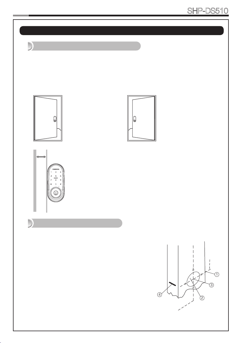
Step 1. Check the Door Status
1) This lock supports door thickness of 1-3/8” to 2-5/32” (35 to 55mm).
2) Using the provided lock template, ensure that there are no obstructions that would prevent
installing the lock properly.
3) Take note of which orientation the deadbolt will need to be installed, left hand or right
hand.
Left-handed Door
When viewed from the
Outside, the hinge is on the
left.
Min. 50mm
Please, be aware of that there has be more than
50mm gap between the door frame.
Right-handed Door
When viewed from the Outside,
the hinge is on the right.
Step 2. Mark on the Door
Check the location and direction of the deadbolt, attach the drilling template (page 27) on
the side of the door, and mark on it with a pen.
1) Align the horizontal line across the door.
2) Align the vertical line over the door.
3) Mark the centers of the holes with the drilling template.
4) Mark the centerline of the deadbolt by aligning it with the
vertical line.
4

Step 3. Drilling
1) Drill a 2-1/8˝ (54 mm) diameter hole through the door, as indicated on
the template, using a hole saw.
2) Drill a 1˝ (25 mm) mortise hole using a hole saw.
3) Drill strike plate holes using a drill bit (1/8˝, 2.5 mm).
Smart
Door Lock
SHP-DS510
② 25mm
① 54mm
2.5mm
③
Step 4. Strike Plate Installation
1) Using the template, locate the center horizontal
line for the deadbolt hole, which lines up with the
center of the 2-1/8˝ hole, and draw a horizontal line
on the door frame to mark where you will make the
deadbolt mortise hole.
2) Measure half the thickness of the door. Now,
measure that distance from where the door stops
at the frame when the door is closed toward the
door jamb and mark a straight, vertical line the
length of the door strike plate. Draw a horizontal
line from the mark you made in Step 1 toward the
vertical line. Where both lines cross, make a 1˝ (25
mm) diameter hole, 1/2˝ (13 mm) in depth.
3) Align the holes of the strike plate with the vertical
line. Trace the outline of the strike plate and
mortise with a 1/16˝ (1.6 mm) indentation. Attach
the strike plate with the 2 screws provided.
FH+ T4 x 19
5
7
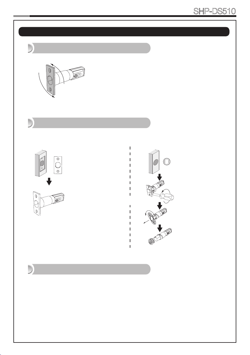
Preparing the parts
180°
OR
|
1. Adjusting the length of the dead bolt
Turn the body of the dead bolt to adjust the length
of the dead bolt.
It can be 60mm (2-3/8”) or 70mm (2-3/4”)
2. Changing the faceplate of the dead bolt
Change the faceplate of the dead bolt following the size of a strike hole.
Smart
Door Lock
SHP-DS510
Rectangle Strike hole
: No need to change.
OR
Round Strike hole
1. Remove the strike
faceplate with a
screw driver.
2. Turn the inner
faceplate to take
out it.
3. Insert the round
faceplate.
3. Adjusting the length of the tailpiece
How to cut
1. Press the V-cut line with pincers to make more cut line.
2. Hold the end of the tailpiece with pincers.(Cut the tailpiece 5mm longer than the door thickness.)
3. Bend it up and down until it is separated.
- For more information, refer to page 31.
6
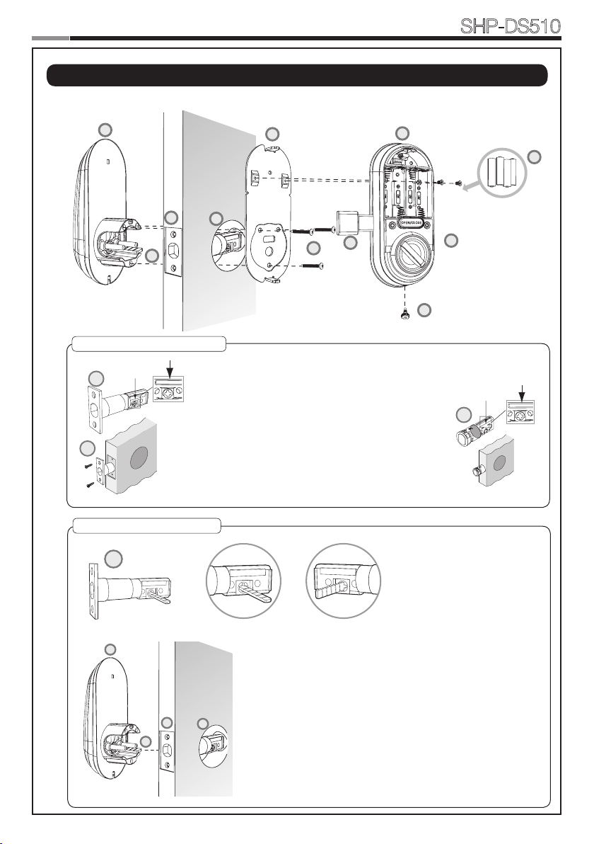
Installing lock
D
A
H
E
REG
SET
C
F
B
J
D
A
G2
G3
G4
E
H
|
Outside
1. Installing the Dead Bolt(E)
Inside
Smart
Door Lock
SHP-DS510
E
G1
1. Before installation
1) Check the faceplate type of your door.
2) Make sure the deabolt directon as shown before
inserting it into a door side.
2. Insert the deadbolt from the side of the door.
3. Fix the deadbolt using two FH+T4X19 screws.
* If there is round strike hole, change the faceplate, and
insert the deadbolt following right side drawing.
D
2. Installing the Exterior Unit
D
Left-handed Right-handed
1. Ensure the Exterior Unit is aligned with the center hole of
the deadbolt and Cut the tailpiece 5mm longer than the
door thickness(refer to the page 31).
2. Attach the exterior unit.
CAUTION: The dead bolt must be in a retracted position.
In case of right-handed door, insert the tailpiece vertically.
In case of left-handed door, insert the tailpiece horizontally.
7
9
REG
SET
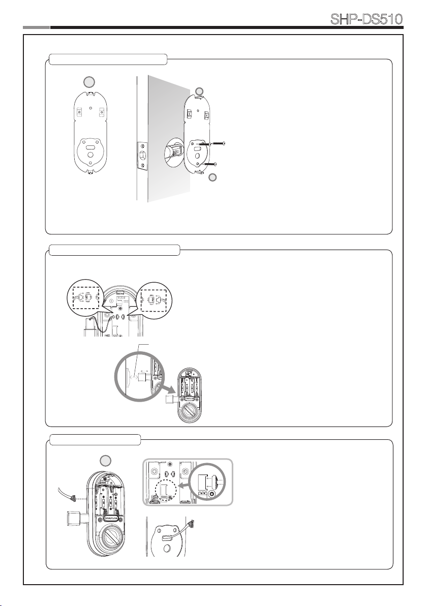
3. Installing the Mounting Plate
C
G2
SET
REG
REG
C
4. Installing the Magnet Sensor Set
Smart
Door Lock
SHP-DS510
1. Detach the Interior Mounting Plate from
the interior unit.
2. Fasten the interior mounting plate with
three TH+M4x40 (G2) 90% of the way.
3. Align the Exterior Unit with the Interior
Mounting Plate and then tighten the
screws.
4. Cover the rubber pad on the Interior
Mounting plate.
CAUTION: Do not over-tighten, and check
the movement of dead bolt by the mechanical key.
5. Connecting the cable
B
Left-handedRight-handed
3/4˝(20mm)
Install the door sensor.
It should be installed in right way of the door.
The user has an option not to use/install the
magnet sensor. In order to disable, the user
shall let the door sensor sense the magnet for
only once in installation for setting of right or left
handed use.
CAUTION: The gap of the door sensor between
the door side and the door-frame should be
within 3/4”(20mm). If the gap is to wide, pull out
the door sensor to adjust the gap enough to
detect.
1. Connect the cable from the exterior unit
to the interior unit.
2. After connecting the cable, push the
cable into the hole of the door.
8

6. Fix Screw for the Interior Unit
C
B
G3
G4
REG
SET
REG SET REG SET
B J
REG
SET
REG
SET
SET
REG
REG
Left-handed Right-handed
7. Final Check
1
2
3
Smart
Door Lock
1. Before installing the interior unit, check the
direction of the thumb turn while the dead bolt is
in the OPEN POSITION.
2. Open the battery cover.
3. Align the Interior Unit on to the Interior Mounting
Plate, and attach it with 3 screws.
CAUTION: Check the movement of the dead bolt
by the thumb turn.
1. Install 4 batteries. A Melody will sound
when all 4 batteries are installed
correctly.
2. Close the door to detect the door
3/4˝(20mm)
sensor. You can hear the beep sound
when the door sensor detects the
magnet. After that, press [OPEN/
CLOSE] button to check whether the
dead bolt works properly.
3. Stick the door sensor with attention
on the distance.
CAUTION: The gap between the door
sensor and the magnet should be close
enough to be detected.
SHP-DS510
OPTION : Connection for Video Intercom
Dry Contact
Signal
Connect the cable of video intercom to the
Interior Unit.
SHP-DS510 receives 1 second of dry con-
tact signal to open the door remotely.
It is normally compatible with SHT-3006 and
other Samsung Video Intercom systems.
9
11
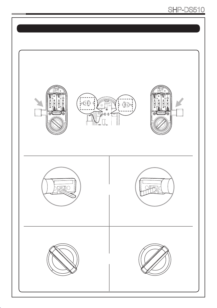
Setting of Right-Handed / Left Handed
REG SET REG SET
|
*All status should be checked while the dead bolt is in OPEN POSITION.
Smart
Door Lock
SHP-DS510
Left-handed
Right-handed
Left-handedRight-handed
Tailpiece
Thumb turn
10
 Loading...