How it Works
Log In / Sign Up
Buy Points
How it Works
FAQ
Contact Us
Questions and Suggestions
Users
Samsung
Loading...
S
SHC-721APH
SHC-721N
SHC-721P
2
SHC-721PH
2
SHC-730N
2
SHC-730N-P
SHC-730P
2
SHC-735
SHC-735-N
SHC-735P
SHC-737
SHC-737-N
3
SHC-737P
SHC-737 Series
SHC-740N
3
SHC-740N/P
SHC-740P
3
SHC-745N
SHC-745P
SHC-745PH
SHC-745 Series
SHC-750
SHC-Z100S
SHC-Z120L
SHC-Z140S
SHD-100C
SHD-200C
SHD-3000F
3
SHD-3000F1
2
SHD-3000F2
SHD-3000F3
SHD-3000F4
SHD-3000FW2
SHD-3000FW3
SHD-300C
SHD-46VDB
SHD-46VDE
SHD-B-3100FP
SHD-B-3100FP1
SHF-1500F
SHG-120
3
SHG-120/220
SHG-120-N
SHG-220
4
SHG-220S
2
SHG-222
2
SHG-B300
SHG-x660
SHM8187WG
SHN WDD510
SHN WDS700
Shoot Wow! WB380F
Shot Wow! WB800F
Showcase
Showcase GALAXY S
2
SHP2100
SHP-3700F
SHP-3700H
SHP-3701F
SHP-3701H
SHP-4300H-N
SHP-700
SHP-A30
2
SHP-DH525
SHP-DP609
SHP-DP727
SHP-DS510
SHP-DS700
SHP-DS705
SHR-1010
2
SHR-1010D
SHR-1010(P)
SHR-1040
2
SHR-1040K
SHR-1041
SHR-1041K
2
SHR-2040
8
SHR-2040P
5
SHR-2040P250
SHR-2040P-GAR
SHR-2041
6
SHR-2042
8
SHR-2042-250-N
2
SHR-2042-N
2
SHR-2042P
2
SHR-2042P2
SHR-2042P250
SHR-2080
5
SHR-2080P
3
SHR-2080P2
SHR-2080P250
2
SHR-2082
9
SHR-2082P
SHR-2082P250
2
SHR-2082P500
3
SHR-2160
8
SHR-2160/2162
SHR-2160P
6
SHR-2160P2
SHR-2 Series
Loading...
Loading...
Nothing found
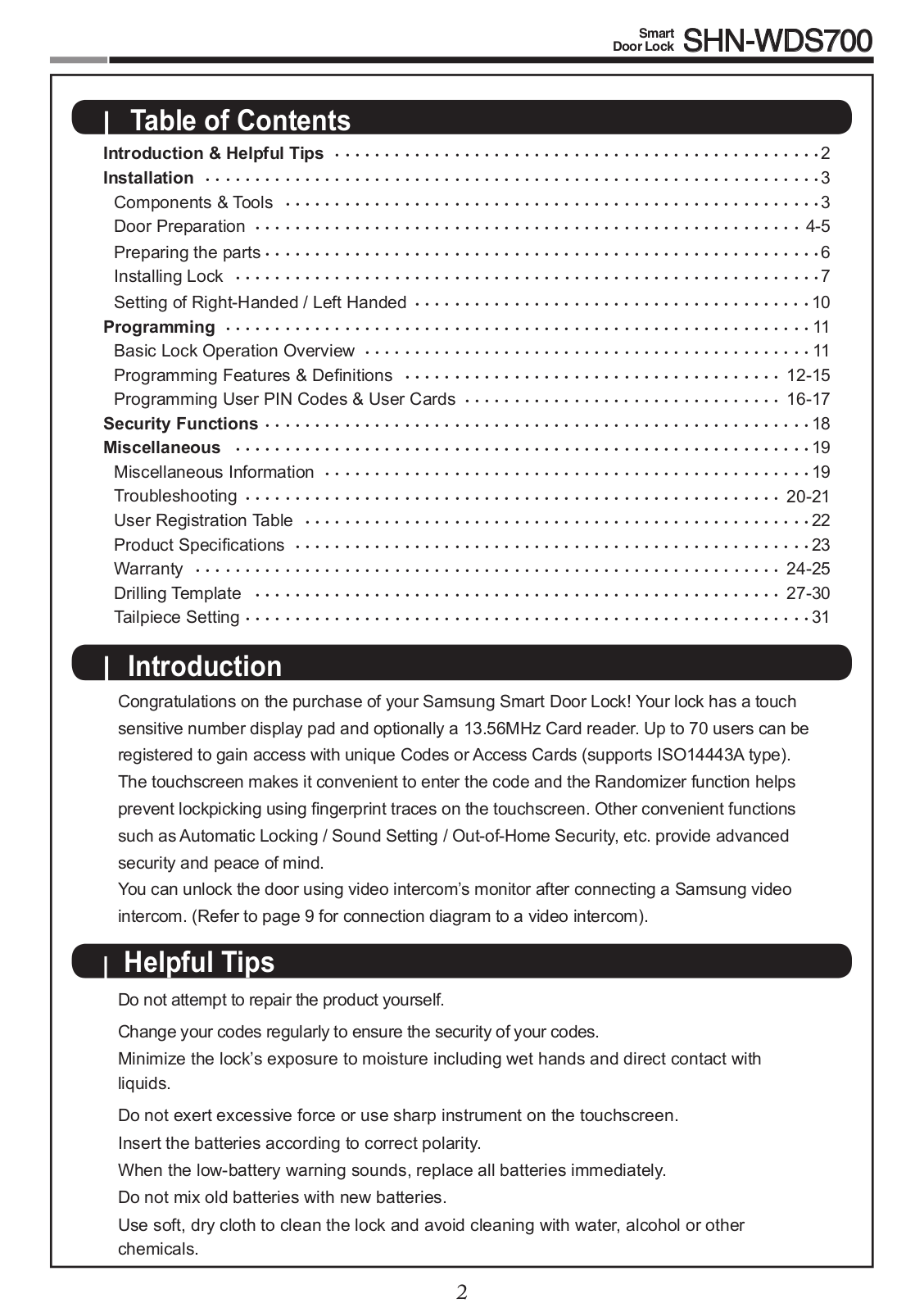
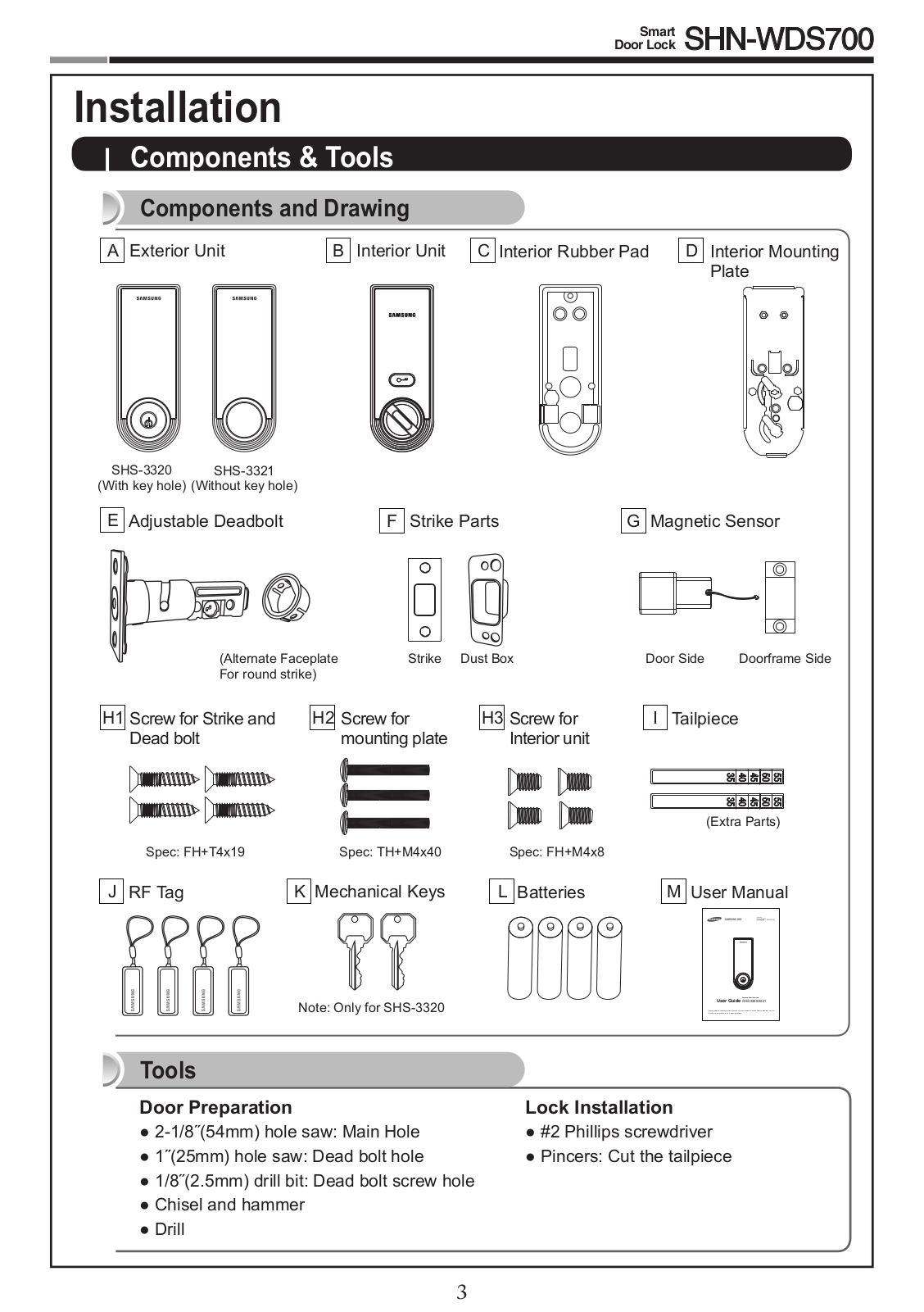
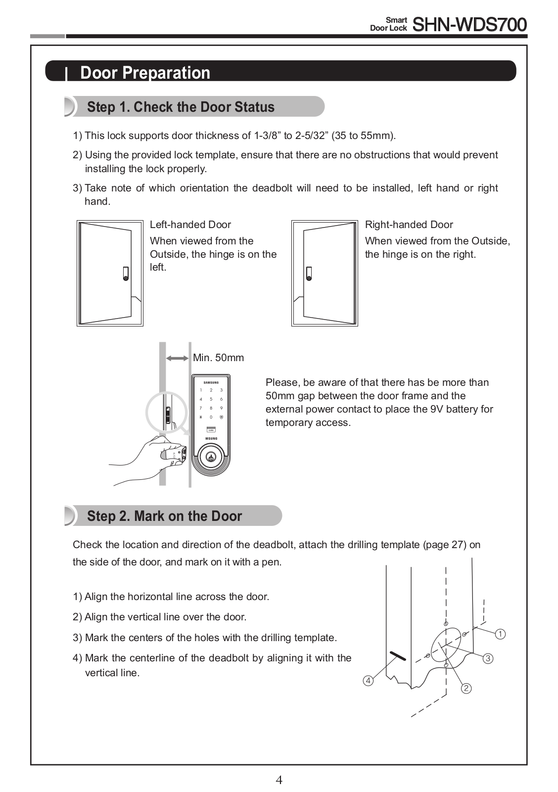
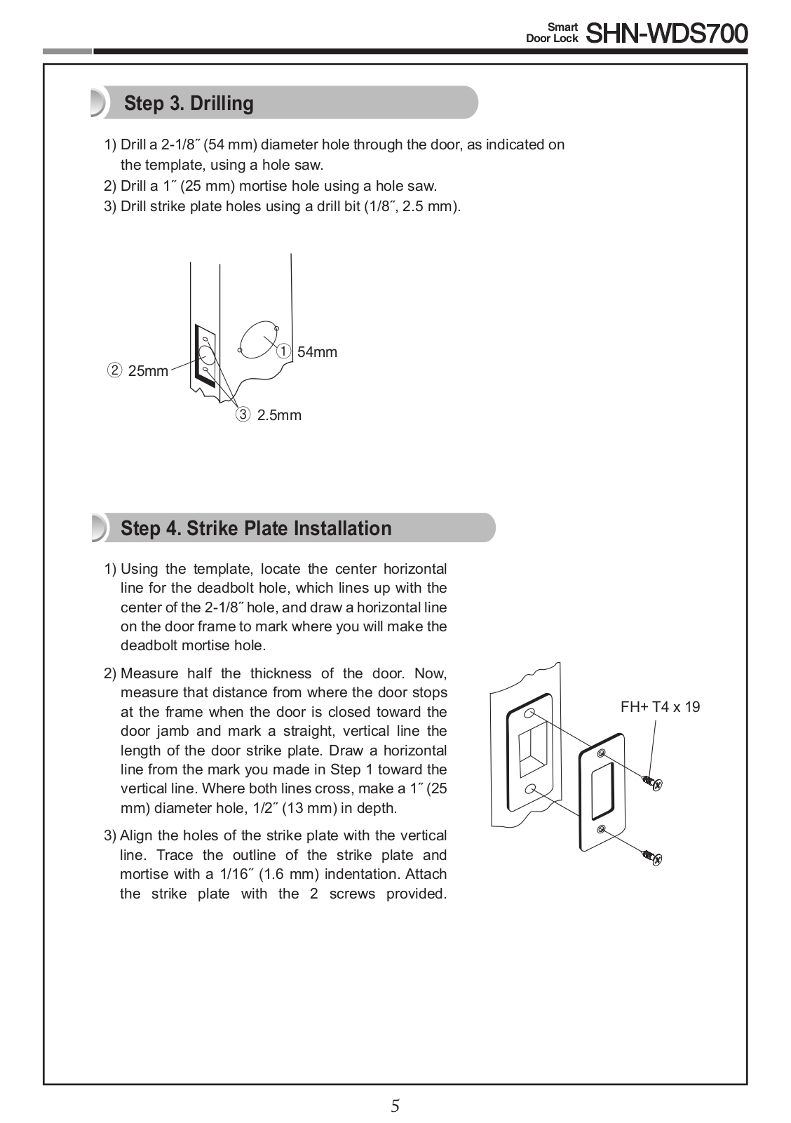
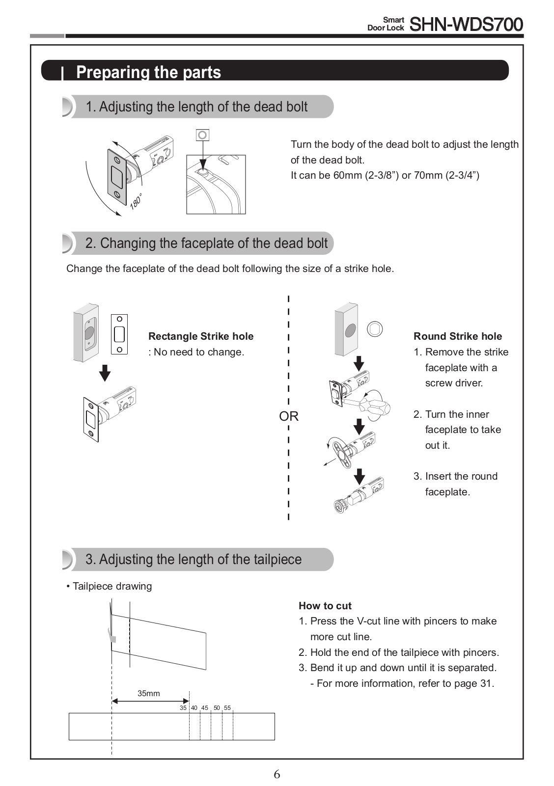
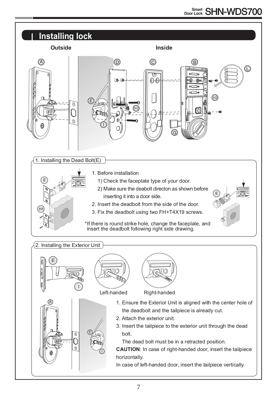
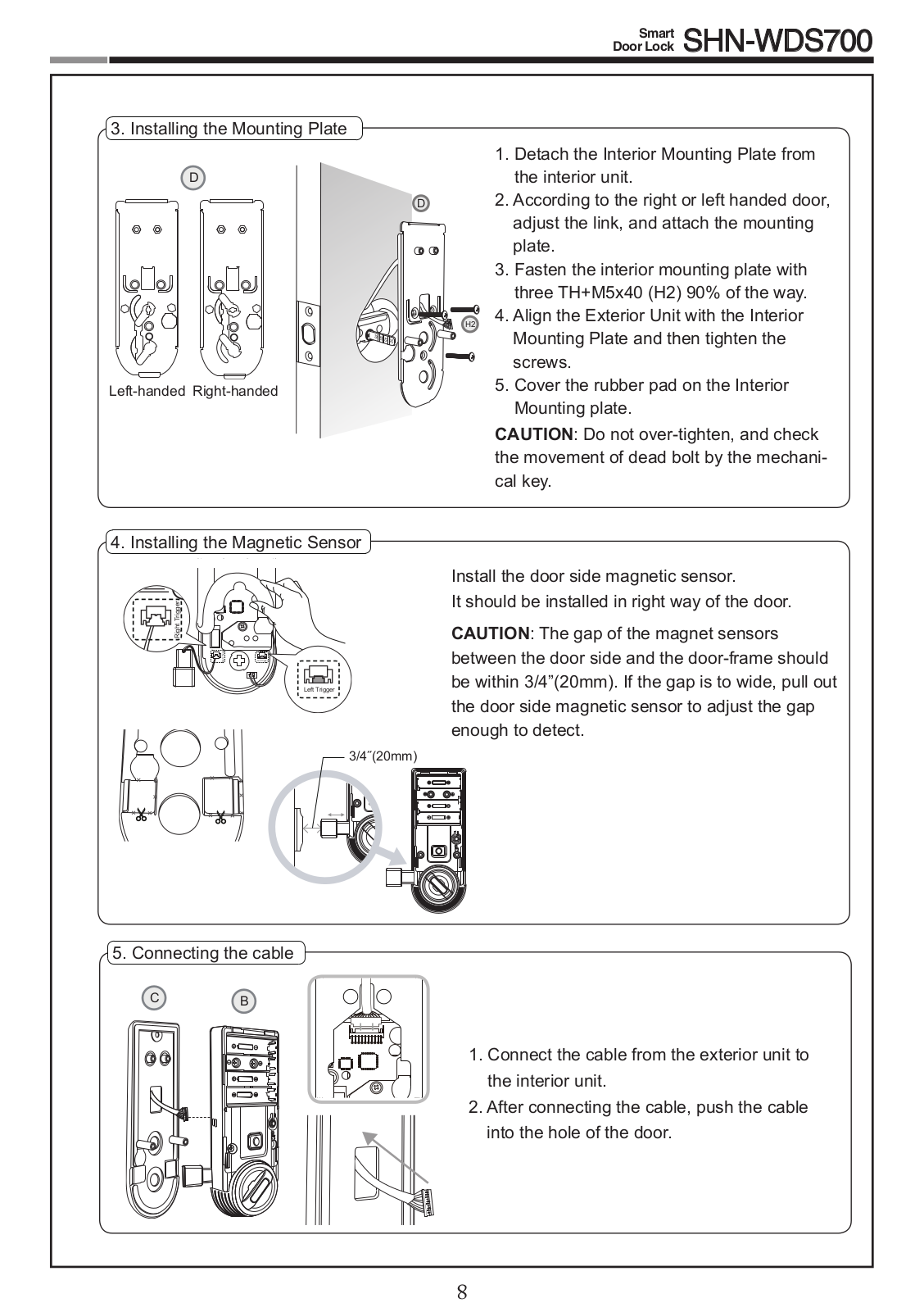
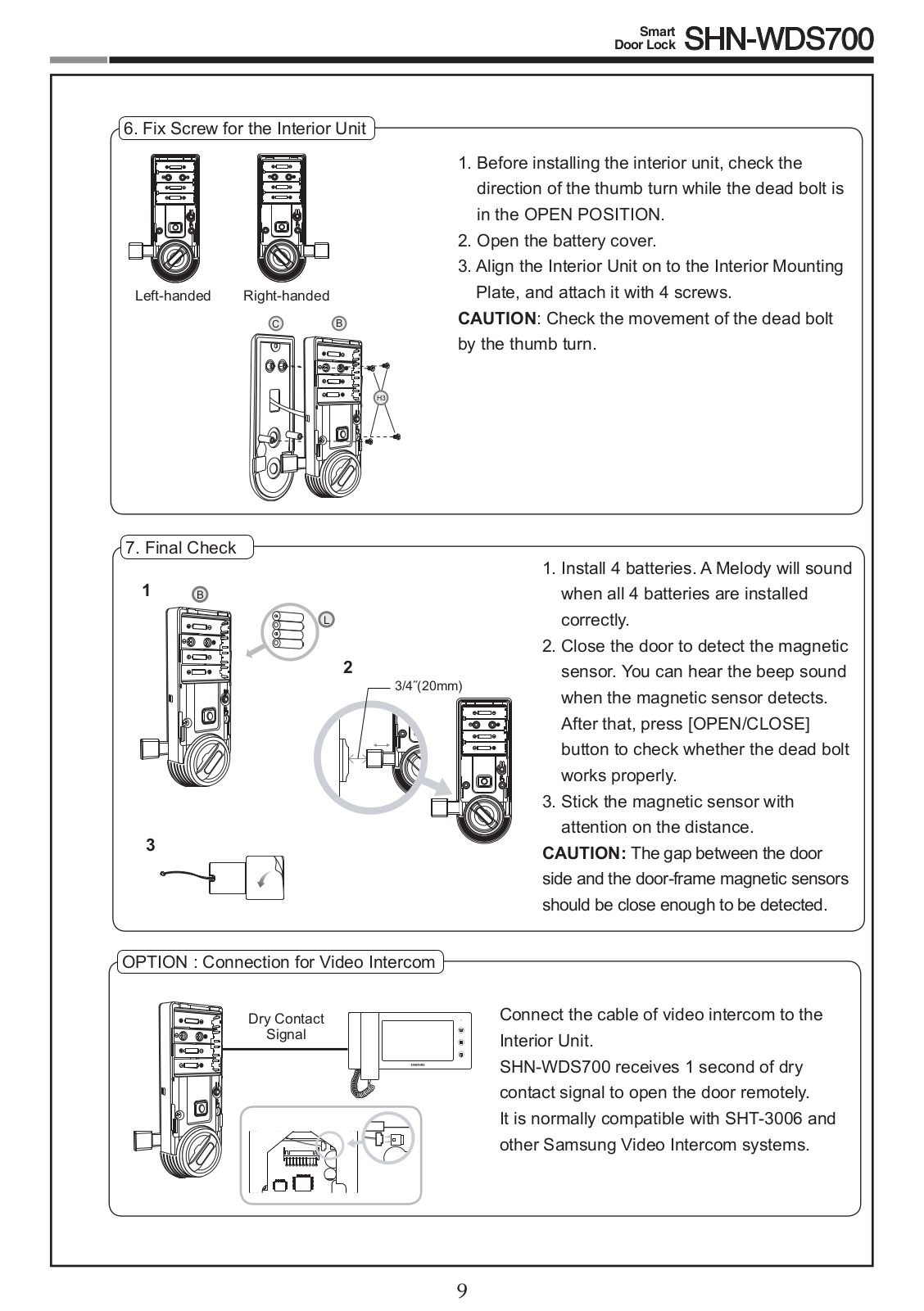
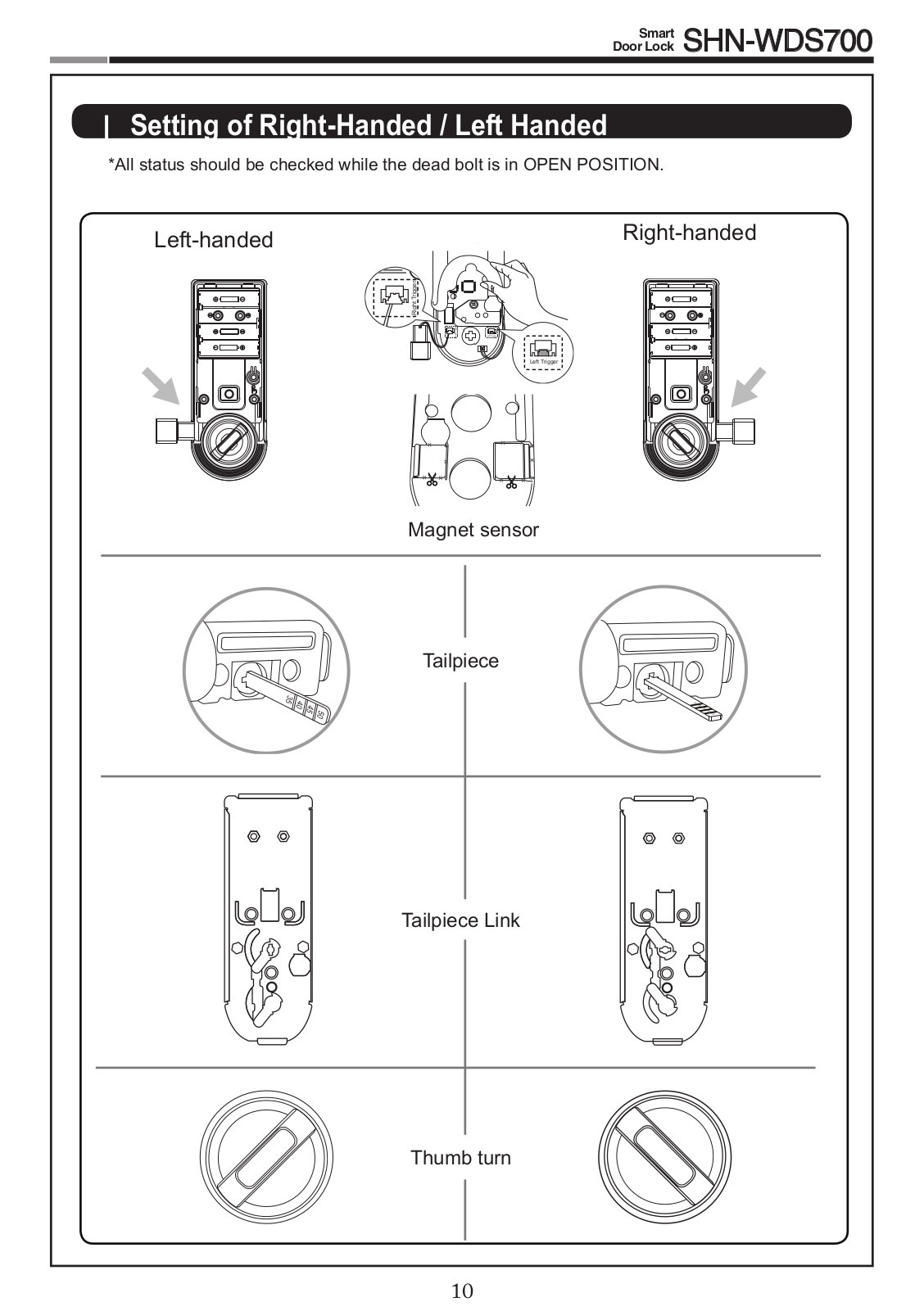
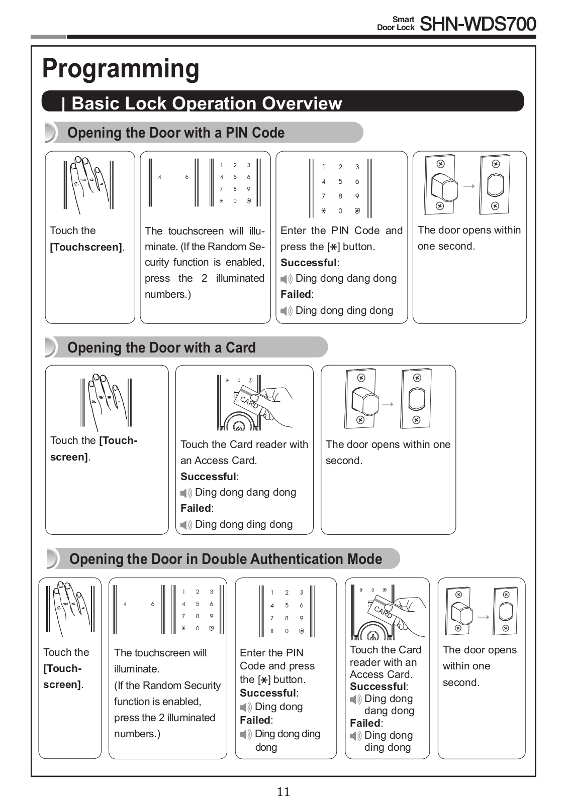
SHN WDS700
User Manual
36 pgs
2.98 Mb
0
Table of contents
Loading...
Samsung SHN WDS700 User Manual
...
Samsung User Manual
Download
Specifications and Main Features
Frequently Asked Questions
User Manual
Download
Loading...
+
25
hidden pages
Unhide
You need points to download manuals.
1 point = 1 manual.
You can buy points or you can get point for every manual you upload.
Buy points
Upload your manuals
 Loading...