

Samsung SHC-735 User Manual

SALES NETWORK
•
SAMSUNG TECHWIN CO., LTD.
333-1, Sangdaewon 1-dong, Jungwon-gu, Seongnam-si, Gyeonggi-do 462-807, Korea
TEL : +82-31-730-8931~3 FAX : +82-31-730-8950
•
SAMSUNG OPTO-ELECTRONICS UK, LTD.
Samsung House, 1000 Hillswood Drive, Hillswood Business Park Chertsey, Surrey KT16 OPS
TEL : +44-1932-45-5308 FAX : +44-1932-45-5325
www.samsungtechwin.com
www.samsungcctv.com
P/No. : Z6806-0828-01A
VAN 07. 08
Supreme Resolution WDR Camera SHC-735 User’s Manual
Thank you for purchasing a SAMSUNG CCD CAMERA.
Before attempting to connect or operate this product,
please read these instructions carefully and save this manual for future use.
ENGLISH
The lightning flash with an arrowhead symbol, within an equilateral triangle is
intended to alert the user to the presence of uninsulated “dangerous voltage”
within the product's enclosure that may be of sufficient magnitude to
constitute a risk of electric shock to persons.
The exclamation point within an equilateral triangle is intended to alert the user
to the presence of important operating and maintenance (servicing)
instructions in the literature accompanying the appliance.
INFORMATION -This equipment has been tested and found to comply with limits
for a Class A digital device, pursuant to part 15 of the FCC Rules. These limits are
designed to provide reasonable protection against harmful interference when the
equipment is operated in a commercial environment. This equipment generates,
uses, and can radiate radio frequency energy and, if not installed and used in
accordance with the instruction manual, may cause harmful interference to radio
communications.
Operation of this equipment in a residential area is likely to cause harmful
interference in which case the user will be required to correct the interference at
his own expense.
WARNING : Changes or modifications not expressly approved by the manufacturer
WARNING : To prevent electric shock and risk of fire hazards:
could void the user’s authority to operate the equipment.
Do NOT use power sources other than that specified.
Do NOT expose this appliance to rain or moisture.
This installation should be made by a qualified service person and
should conform to all local codes.

Contents
Features
Precautions
Components and Accessories
Overview
Front View
Side View
Bottom View
Rear View
Installation Procedures
Lens
• When Using Auto Iris Lens
• When Using C/CS Mount Lens
Connecting a Monitor
Connecting Power
Control via RS-485 Interface
6
8
10
11
11
12
13
14
15
15
19
20
21
How to Use the Camera
Function Menu Structure
How to Set up the Functions
LENS
EXPOSURE
WHITE BALANCE
BACKLIGHT
SSNR
DAY/NIGHT
IMAGE ADJ
SPECIAL
EXIT
Troubleshooting
Specifications
22
22
23
24
26
28
29
31
32
34
36
40
41
43

Features
Ultra High Resolution
By adopting a double-speed 410,000 pixel Sony CCD, the
camera produces clear picture quality with a horizontal
resolution of 560 TV lines for color, and 700 TV lines for B/W.
Wide Dynamic Range (WDR):
By adopting a proprietary SV-IV DSP chip, the camera
delivers clear, high quality pictures even in backlight, by
increasing exposure in dark areas while decreasing it in
bright areas; a corrected image with clear details results.
Excellent Sensitivity
Adopting a Diagonal 6mm (1/3"), highly sensitive CCD and
digital signal processing technology, it can clearly
distinguish the outline and color of a subject in an
extremely low luminance environment – even, for example,
under starlight. Since surveillance is possible in places
where the light is poor, the camera is appropriate for day and
night surveillance outdoors or on the outside of buildings.
- 0.001 Lux (Color Sens-up Mode)
- 0.00004 Lux (B/W Sens-up Mode)
SSNR (Samsung Super Noise
Reduction) Function
The high performance SV-IV DSP chip dramatically reduces
the gain noise in digital image processing, producing clear,
sharp images in low lighting environments.
Motion Detection
Since the camera detects motion and generates
signals without any additional external sensors, you
can monitor activity more efficiently by connecting the
camera to an alarm device.
DIS (Digital Image Stabilizer)
The DIS function compensates for any camera
movement, to produce more stable pictures.
Video/DC Drive Lens Support
You can select Video or DC Drive Lens from the menu.
Miscellaneous Functions
SYNC (INT/LL), SENS-UP, FREEZE, FLIP (H/V-REV),
D-ZOOM, SHARPNESS, MOTION DETECTION and
PRIVACY functions are provided.
RS-485 Communication
Control Support
Remote OSD menu control via an RS-485 interface is
supported.
Samsung Techwin cares for the environment at all product manufacturing
stages to preserve the environment, and is taking a number of steps to
provide customers with more environment-friendly products.The Eco mark
represents Samsung Techwin s will to create environment-friendly products,
and indicates that the product satisfies the EU RoHS Directive.
Warnings & Cautions
This information is provided to ensure your safety and to prevent any losses,
financial or otherwise. Please read it carefully and use the product accordingly.
* For product inquiries, please contact the retail shop where you bought the camera. The use of
equipment such as an aerial ladder while providing after-sales service shall be at your expense.
Warning/Attention/Special Mark Messages
Ignoring this information may result in material loss and/or serious
personal injuries including death.
Indicates “Never Allowed.”
Indicates “No Disassembling.”
Indicates
Must Observe.
Day & Night
The camera identifies whether it is day or night and
automatically switches to the appropriate mode, depending
on its environment. By day, the camera switches to color
mode in order to maintain optimal color. At night, it switches
to B/W mode so as to obtain better picture definition.
COLOR CCD CAMERA User’s Manual
6
OSD
The camera control is convenient by using 7 different
foreign language O.S.D.
- NTSC : Korean, English, Spanish, Japanese
- PAL : English, French, German, Spanish, Italian,
Chinese
COLOR CCD CAMERA User’s Manual
7

Precautions
Do not install under extreme
temperature conditions.
Use only under temperature conditions
between -10˚C and +50˚C. Provide good
ventilation when using in high temperature
conditions.
Do not install under unstable
lighting conditions.
Severe lighting changes or flickering may
hinder normal camera operation.
Do not install in high humidity
environment.
May lower image quality.
Avoid touching the camera lens.
The lens is the most important component
of the camera. Be careful not to smear it
with fingerprints.
Do not drop the camera or
subject it to physical shock.
May cause a product malfunction.
Do not expose the camera to
rain or other types of liquids.
Wipe dry any liquids. Liquids may contain
minerals that are corrosive to electronic
Never keep the camera face to
strong light directly.
May damage the CCD.
Do not expose the camera to
radioactivity.
Radioactivity exposure may damage the
CCD.
components.
Notes
• Exposure to a spotlight or an object emitting strong light may cause smear or
blooming.
• Ensure that the power source complies with normal specifications before supplying
it to the camera.
COLOR CCD CAMERACOLOR CCD CAMERA User’s ManualUser’s Manual
98
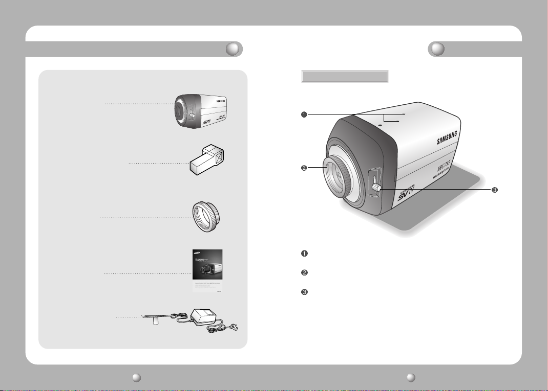
1. Ultra High Resolution
WDR Color CCD Camera SHC-735
2. Auto Iris Lens Connector Plug
3. C-Mount Adapter
4. Instruction Manual
5. AC 24V/500mA Adapter
OverviewComponents and Accessories
Front View
Tripod Mounting Bracket Screw Hole
Used to fix the Tripod Mounting Bracket to the top of the camera.
C-Mount Lens Adapter
Install this adapter to use a C-Mount Lens.
Back Focus Control Lever
Adjust focus by this Back Focus Lever.
COLOR CCD CAMERACOLOR CCD CAMERA User’s ManualUser’s Manual
1110

Overview
L
Side View
Auto Iris Lens Connector
Used to connect Auto Iris Lens plug.
Bottom View
Tripod Mounting Bracket Screw Hole
Used to fix the camera on a bracket or tripod.
The screw sizes for this hole are as follows:
You can separate the Tripod Mounting Bracket and
install it on the top or bottom of the camera.
Make sure to use the Tripod Mounting Bracket when
fixing the camera to a bracket or tripod. Otherwise the
camera may not be secure, or the internal circuitry of
the camera may be damaged.
COLOR CCD CAMERACOLOR CCD CAMERA User’s ManualUser’s Manual
1312
1/4"-20 UNC (20 THREAD)
L:4.5mm±0.2mm (ISO standard),
or 0.197" (ASA standard)

Overview
Installation Procedures
Rear View
Function Setup Button
SET Button : Displays the menu on the screen. Press this button to confirm
Up and Down Button : Used to move the cursor up or down in the menu
Left and Right Button : Used to move the cursor left or right in the menu
D & N Input Port
You can switch to Day & Night Mode by connecting an external signal to this port.
MD Output Port
Motion detection signals are output through this port.
RS-485 Control Port
You can control SETUP MENU through this port by using external controllers like a
Remote controller that RS-485 Communication is supported. For details, see page 21.
Video OUT Port
Video signals are output through this port. Connect this port to the Video IN port of a monitor.
Power LED
When power is properly connected, this LED comes on.
Power IN Port
Connect the power as specified for each model here.
status or after changing a selected item.
screen to select a desired menu item.
screen or to change the value of the selected item.
Lens
The lens is not supplied with this camera. Purchase a lens suitable for your
environment. This camera accepts the auto iris lens and both C-and CS-mount lens.
Notes
• It is recommended to use the DC type Auto Iris Lens to effectively enjoy the major
functions of this camera.
• Keep the lens surface clean, since if it is contaminated with dirt or fingerprints the
picture quality suffers.
When Using Auto Iris Lens
1. Strip the insulation of the auto iris lens cable 8mm from the end.
approx. 8mm
2. Strip the insulation of the core of the auto iris lens cable to expose a 2mm length.
approx. 2mm
COLOR CCD CAMERACOLOR CCD CAMERA User’s ManualUser’s Manual
1514
 Loading...