

SAMSUNG SH18ZV_XEF.40208.1.16 Service Manual
ROOM AIR CONDITIONER
INDOOR
AQT24A1QE/B
AQT24B1QE/B
AQ18A1QE/B
AQ18B1QE/B
SH24ZV
SH18ZV
SERVICE
INDOOR
AQT24A2QE/B
AQT24B2QE/B
AQ18A2QE/B
AQ18B2QE/B
Manual
CONTENTSAIR CONDITIONER
1. Pre c a u t i o n s
2. Product Specifications
3. Operating Instructions and
I n s t a l l a t i o n
4. Disassembly and Reassembly
5. Tro u b l e s h o o t i n g
5. Exploded Views and Parts List
6. Block Diagrams
7. PCB Diagrams
8. Wiring Diagrams
9. Schematic Diagrams

© Samsung Electronics Co., Ltd. JAN.1999.
Printed in Korea.
Code No. DB81-00030A(1)
1. Precautions
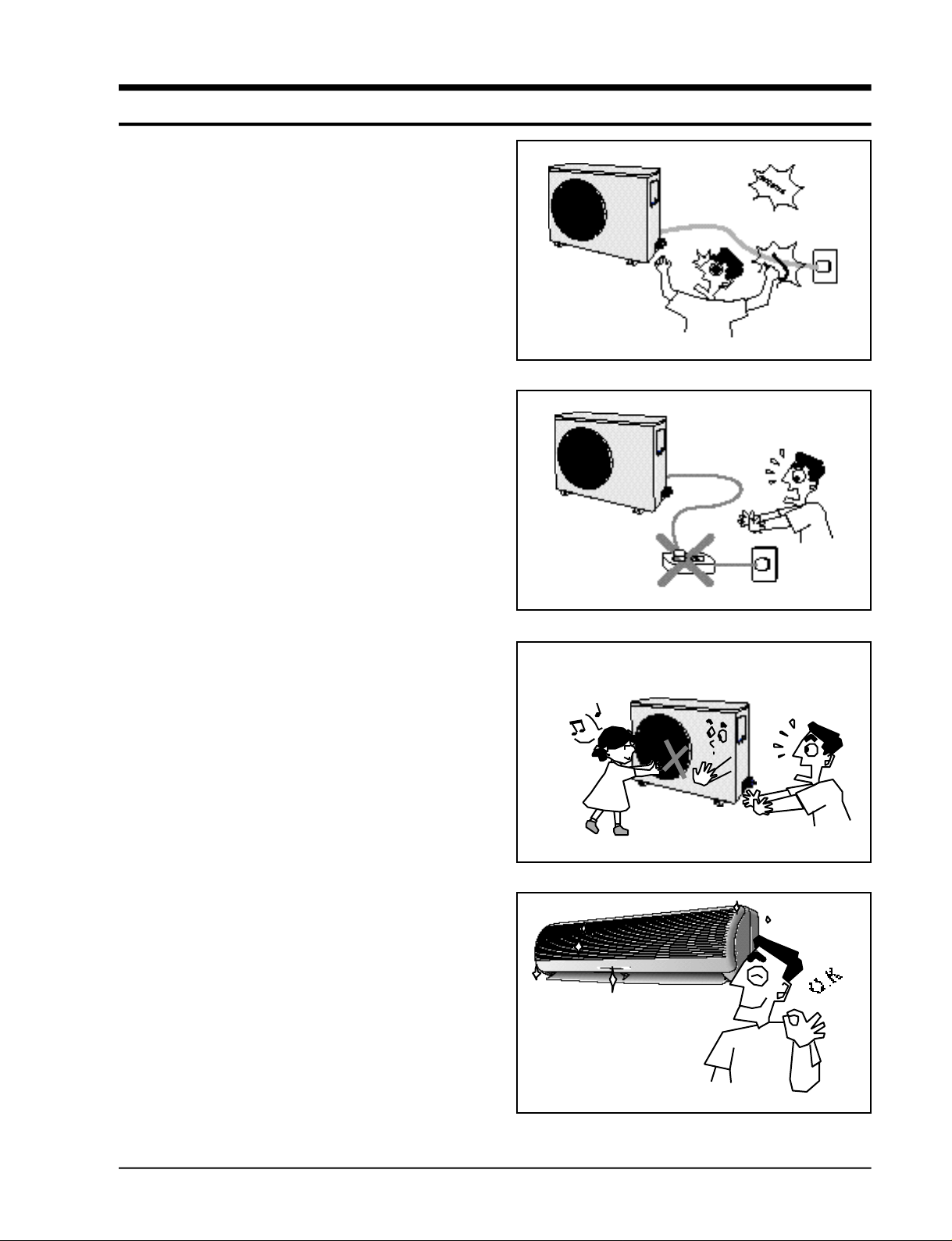
1 . Warning: Prior to re p a i r, disconnect the
power cord from the circuit bre a k e r.
2 . Use proper parts: Use only exact re p l a c e-
ment parts. (Also, we recommend re p l a c i n g
parts rather than repairing them.)
3 . Use the proper tools: Use the proper tools
and test equipment, and know how to use
them. Using defective tools or test equipment may cause problems later- i n t e r m i t t e n t
contact, for example.
4 . Power Cord: Prior to re p a i r, check the
power cord and replace it if necessary.
5 . Avoid using an extension cord, and avoid
tapping into a power cord. This practice
may result in malfunction or fire .
6 . After completing repairs and re a s s e m b l y,
check the insulation resistance. Pro c e d u re :
Prior to applying power, measure the re s i stance between the power cord and the
g round terminal. The resistance must be
g reater than 30 megohms.
Fig. 1-1 Avoid Dangerous Contact
Fig. 1-2 No Tapping and No Extension Cords
7 . Make sure that the grounds are adequate.
8 . Make sure that the installation conditions
a re satisfactory. Relocate the unit if necess a r y.
9 . Keep children away from the unit while it is
being re p a i re d .
1 0 . Be sure to clean the unit and its surro u n d-
ing are a .
Fig. 1-3 No Kids Nearby!
Fig. 1-4 Clean the Unit
Samsung Electronics
1-1

M E M O
1-2
Samsung Electronics
2. Product Specifications
2-1 Table
Item
Power Sourse
Performance
Electrical
Rating
Features
D i m e n s i o n s
&
Weight
Model
UNIT
Capacity
Air circulation (High) m3/min
Moisture removal (High) Liters/h
Available voltage range V
Running amperes A
Power input kw
Power factor %
Energy efficiency ratio BTU/wh
Compressor locked rotor amperes A
Controls/Temperature control
Control unit
Timer
Fan speed Indoor/Outdoor
Airflow direction (indoor) Horizontal
Vertical
Comperssor
Refrigerant/Amount charged at rating g
Refrigerant control
(Sound pressure) Indoor Hi/Me/Lc dB-A
Outdoor-Hi dB-A
Refrigerant tubing connections
Max. allowable tubing length at shippint m
Refrigerant tube diameter Narrow tube (in.)
Wide tube (in.)
Refrigerant tube kit/Accessories
Unit dimensions Height mm
Width mm
Depth mm
Package dimensions Height mm
Width mm
Depth mm
Weight Net kg
Shipping kg
AQT24A1(B1)QE / AQT24A2(B2)QE / SH24ZV
Cool Heat
220-240V~, 50Hz
BTU KW BTU KW
24,000BTU/h 6.80KW 24,000BTU/h 6.90KW
14.0 14.0 14.5 14.5
3.0
198 ~ 264
12.5 12.5 13.0 13.0
2.6 2.6 2.7 2.65
86.7 86.7 86.5 84.9
9.2 - 8.9 82
Microprocessor / I.C Thermostat
Wireless remote control
Q-Timer / 24-Hour ON or OFF
3 Steps and Turbo / 1 Step
Manual
Auto
Reciprocating(Tecumseh)
R22 / 1,600g
Capillary tube
45 / 43 / 41
58
Flare type
10
6.35(1/4”)
15.88(5/8”)
Optional / Hanger-plate
Indoor unit Outdoor Indoor unit Outdoor Indoor unit Outdoor Indoor unit Outdoor
275
1080
204
372
1153
272
13
16
638
880
310
851
1023
413
63.0
67.0
24,000BTU/h - 24,000BTU/h -
AQT24A1(B1)QB / AQT24A2(B2)QB
Cool Heat
220V~, 60Hz
BTU KW BTU KW
14.0 - 14.5 -
3.0
187 ~ 253
13.0 - 13.5 -
2.6 - 2.7 -
90.9 - 90.9 -
9.2 - 8.9 73
Microprocessor / I.C Thermostat
Wireless remote control
Q-Timer / 24-Hour ON or OFF
3 Steps and Turbo / 1 Step
Manual
Auto
Reciprocating(Tecumseh)
R22 / 1,600g
Capillary tube
45 / 43 / 41
58
Flare type
10
6.35(1/4”)
15.88(5/8”)
Optional / Hanger-plate
275
1080
204
372
1153
272
13
16
638
880
310
851
1023
413
63.0
67.0
AQ18A1(B1)QE / AQ18A2(B2)QE / SH18ZV
Cool Heat
220-240V~, 50Hz
BTU KW BTU KW
18,000BTU/h 5.10KW 20,000BTU/h 5.60KW
13.5 13.5 14.0 14.0
2.5
198 ~ 264
8.3 8.3 8.5 8.5
1.85 1.80 1.95 1.85
92.9 90.4 95.6 90.7
9.7 - 10.3 35
Microprocessor / I.C Thermostat
Wireless remote control
Q-Timer / 24-Hour ON or OFF
3 Steps and Turbo / 1 Step
Manual
Auto
Rotary(SAMSUNG)
R22 / 1,550g
Capillary tube
45 / 42 / 39
55
Flare type
10
6.35(1/4”)
12.70(1/2”)
Optional / Hanger-plate
275
1080
204
372
1153
272
13
16
620
787
320
680
926
451
46.0
50.0
AQ18A1(B1)QB / AQ18A2(B2)QB
Cool Heat
220V~, 60Hz
BTU KW BTU KW
18,000BTU/h - 20,000BTU/h -
13.5 - 14.0 -
2.5
187 ~ 253
8.5 - 9.0 -
1.85 - 1.95 -
98.9 - 98.5 -
9.7 - 10.3 35
Microprocessor / I.C Thermostat
Wireless remote control
Q-Timer / 24-Hour ON or OFF
3 Steps and Turbo / 1 Step
Manual
Auto
Rotary(SAMSUNG)
R22 / 1,550g
Capillary tube
45 / 42 / 39
55
Flare type
10
6.35(1/4”)
12.70(1/2”)
Optional / Hanger-plate
275
1080
204
372
1153
272
13
16
620
787
320
680
926
451
46.0
50.0
Remarks : Rating Conditions are :
Indoor air temperature ISO(50Hz) : 27˚C DB/19.0˚C WB, ISO(60Hz) : 27.0˚C DB/19.5˚C WB
Outdoor air temperature ISO : 35.0˚C DB/24.0˚C WB
Samsung Electronics
2-1
2-2 Major Component specifications
■
Indoor unit
Model
Part No.
PCB
Fan &
Fan
Motor
S-Motor
H e a t
E x c h .
Controls
Control circuit fuse
Type
Dia. and length mm
Fan motor model
Pols,rpm(at 240V)
Normal out W
Coil resistance(Ambient temp.20˚C) Ω
Safety devices Type
Operating temp. Open ˚C
Run capacitor µF x VAC
Type
Model
Rating
Coil resistance (Ambient temp. 25˚C) Ω
Coil
Rows x Steps
Fin pitch mm
Face area m
AQT24A1(B1)QE / AQT24A2(B2)QE / SH24ZV
PD-Q24B1Q-03
Microprocessor
250V, 3.15A
Cross-Flow
ø95/L = 842
IC-9430SKJ5A
4P, 1350 RPM
40W
MAIN : 160Ω
SUB : 227Ω
17AM034A5
135 ± 5°C
1.2µF X 450VAC
MSFCC20A03
DC 12V
530Ω
AL-FIN/Copper tube
2 x 15
2
1.2
0.315
AQT24A1(B1)QB / AQT24A2(B2)QB
PD-Q24B1Q-03
Microprocessor
250V, 3.15A
Cross-Flow
ø95/L = 842
IC-9430SKF6A
4P, 1350 RPM
40W
MAIN : 140Ω
SUB : 280Ω
17AM034A5
135 ± 5°C
1.2µF X 450VAC
MSFCC20A03
DC 12V
530Ω
AL-FIN/Copper tube
2 x 15
1.2
0.315
AQ18A1(B1)QE / AQ18A2(B2)QE / SH18ZV
PD-Q24B1Q-09
Microprocessor
250V, 3.15A
Cross-Flow
ø95/L = 842
IC-9430SKJ5A
4P, 1350 RPM
40W
MAIN : 160Ω
SUB : 227Ω
17AM034A5
135 ± 5°C
1.2µF X 450VAC
MSFCC20A03
DC 12V
530Ω
AL-FIN/Copper tube
2 x 15
1.5
0.315
AQ18A1(B1)QB / AQ18A2(B2)QB
PD-Q24B1Q-09
Microprocessor
250V, 3.15A
Cross-Flow
ø95/L = 842
IC-9430SKF6A
4P, 1350 RPM
40W
MAIN : 140Ω
SUB : 280Ω
17AM034A5
135 ± 5°C
1.2µF X 450VAC
MSFCC20A03
DC 12V
530Ω
AL-FIN/Copper tube
2 x 15
1.5
0.315
■
Outdoor unit
C o m p re s s o r
Fan &
Fan
Motor
Heat
E x c h .
Model
Type
Compressor model
Normal output W
Comperssor oil kind
Comperssor oil cc
Oil Specific gravity
Coil resistance(Ambient temp.25˚C) Ω
Safety devices Type
Overloal relay
Operating temp. Open ˚C
Close ˚C
Operating amp(Ambient temp.)
Run capacitor µF x VAC
Type
Dia. and length mm
Fan motor model
Pols, rpm(at240V)
Normal output W
Coil resistance(Ambient temp.20˚C) Ω
Safety devices Type
Operating temp. Open ˚C
Close ˚C
Run capacitor µF x VAC
Coil
Rows x Steps
Fin pitch mm
Face area m
UQT24A1(B1)QE / UQT24A2(B2)QE / XSH24ZV
Reciprocating
AWG5532EXC
2660
WITCO LP200 OR EQUIVALENT
INITIAL : 1125 REFILL : 1066
0.92
Start winding : 2.49
Run winding : 0.81
15HM2415-148
Internal Line Break
120
69
73.0 AT 2-10 SECOND
45MF X 370VAC
Propeller
ø460
OSME-716SRC
6P, 850 RPM
70W
MAIN : 58Ω - 88Ω
SUB : 85Ω - 150Ω
17AM034A5
135±5°C
3µF x 450VAC
AL-FIN / Copper tube
2 x 24
1.7
2
0.5376
UQT24A1(B1)QB / UQT24A2(B2)QB
Reciprocating
AWG5528EXN
2830
WITCO LP200 OR EQUIVALENT
INITIAL : 1125 REFILL : 1066
0.92
Start winding : 1.94
Run winding : 0.88
15HM2415-148
Internal Line Break
120
69
73.0 AT 2-10 SECOND
35MF X 370VAC
Propeller
ø460
OSME-716SRC
6P, 850 RPM
70W
MAIN : 58Ω - 88Ω
SUB : 85Ω - 150Ω
17AM034A5
135±5°C
3µF x 450VAC
AL-FIN / Copper tube
2 x 24
1.7
0.5376
UQ18A1(B1)QE / UQ18A2(B2)QE / XSH18ZV
Rotary
48B180JV1E7
1885
SUNSO-4GSD-T
600
0.92
Common to main : 1.84
Common to sub : MRA12016-12007
External Line Break
165°C
74°C
120·°C : 10.7A 130°C : 9.4A
40µF X 450VAC
Propeller
ø405
AMASS-035AVEB
4P, 1050 RPM
35W
MAIN : 186Ω
SUB : 210Ω
17AM037A5
150±5°C
2.5µF x 450VAC
AL-FIN / Copper tube
2 x 24
1.7
0.504
UQ18A1(B1)QB / UQ18A2(B2)QB
Rotary
48B190IV2E7
1885
SUN1SO-4GSD-T
600
0.92
Common to main : -
Common to sub : MRA12016-12007
External Line Break
165°C
74°C
120·°C : 10.7A 130°C : 9.4A
40µF X 450VAC
Propeller
ø405
AMASS-035ZTEA
4P, 1050 RPM
35W
MAIN : 127Ω
SUB : 165Ω
17AM037A5
150±5°C
2.5µF x 450VAC
AL-FIN / Copper tube
2 x 24
1.7
0.504
2-2
Samsung Electronics
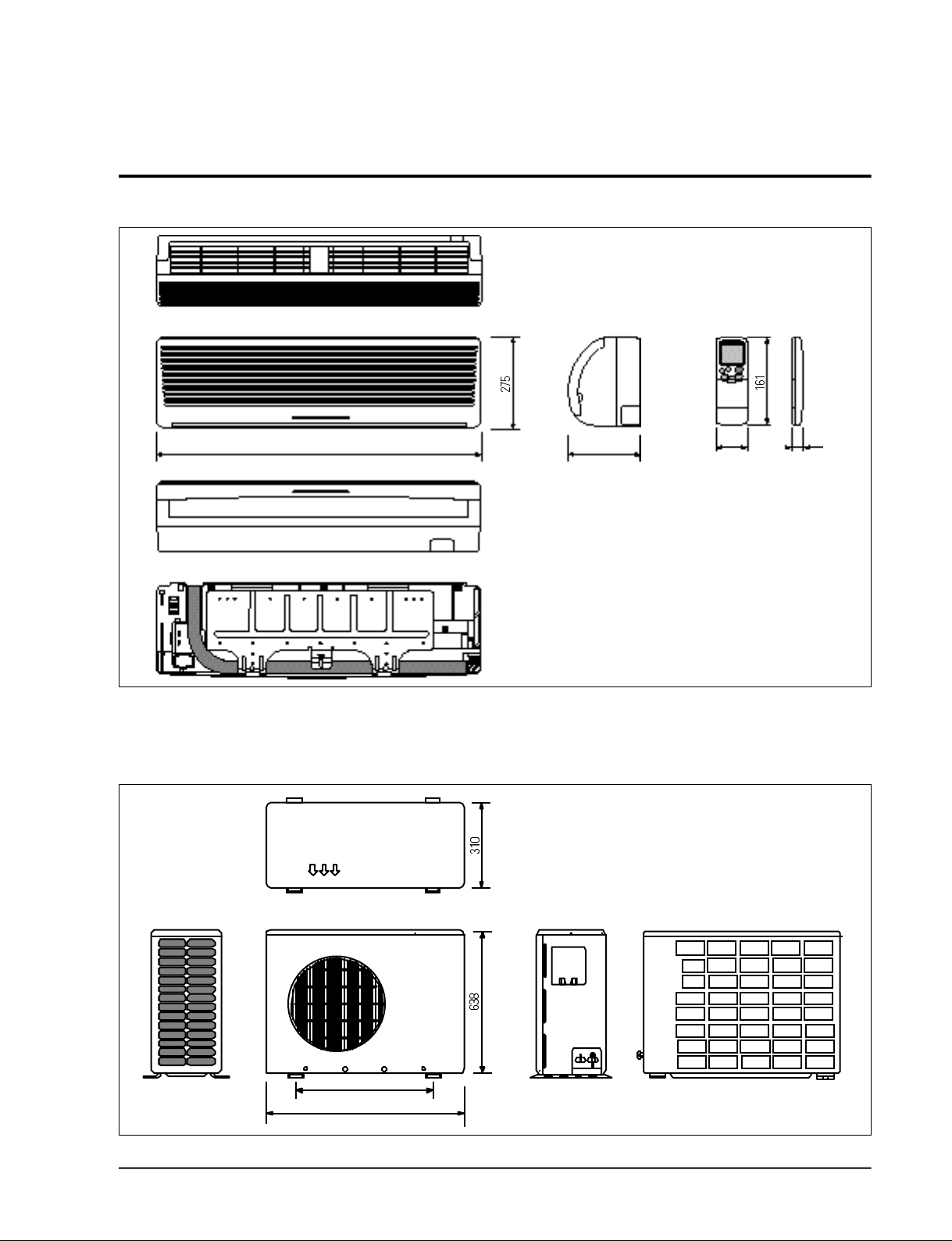
2-3 Dimensions
2-3-1 Indoor Unit
(Front view)
(Remote control)
(Rear view)
2-3-2 Outdoor Unit
2-3-2(a) 24K BTU
1080 204
58 22
Samsung Electronics
(Front view) (Rear view)
660
878
2-3
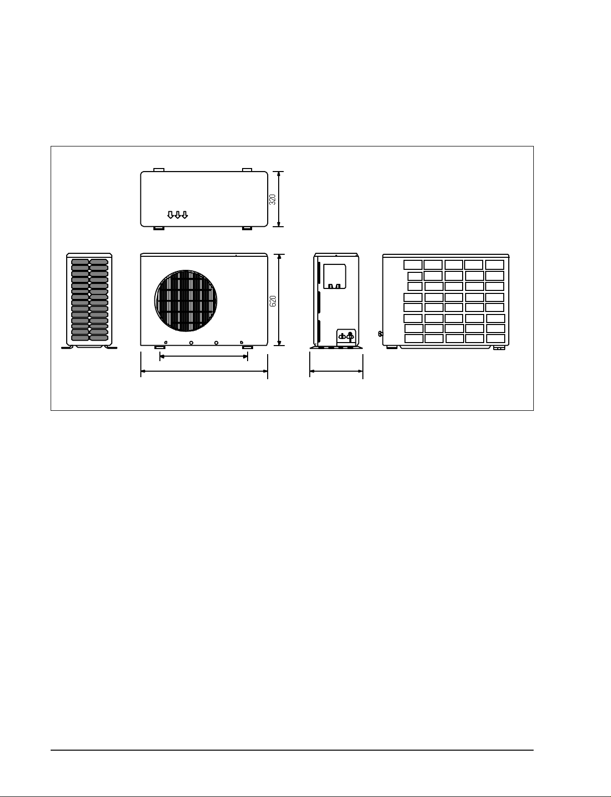
Product Specifications
2-3-3(b) 18K BTU
(Front view) (Rear view)
582
787
340
2-4
Samsung Electronics
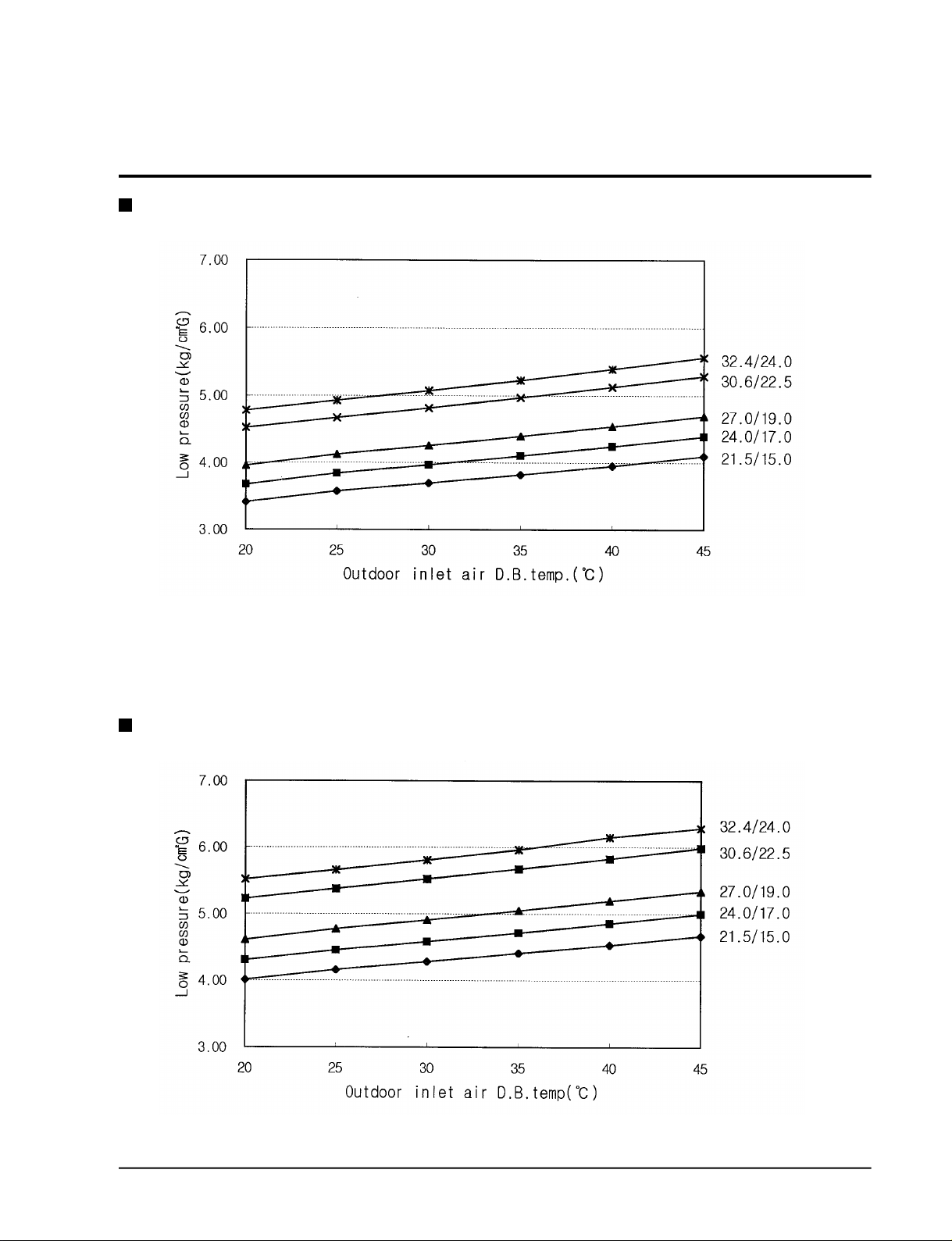
2-4 Pressure Graph
24K BTU
18K BTU
Samsung Electronics
2-5

M E M O
2-6
Samsung Electronics
3. Operating Instructions and Installation
3-1 Operating Instructions
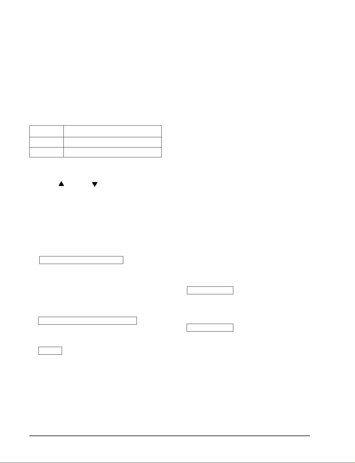
3-1-1 Name & Function of Key in remote controller
NO
1
2
3
4
5
6
7
8
NAMED OF KEY
MODE
TURBO
OFF
(UP)
(DOWN)
FUNCTION OF KEY
On/Off Button. Use this button to start and stop air conditioner.
Temp. up button. If the button is pressed once,
the setting temperature is increased by 1°C
Temp. down button. If the button is pressed once,
the setting temperature is decreased by 1°C
Each time you press this button,
MODE is changed in the following order.
Use this button to provide heavy duty cooling & Heating for 30 minutes.
Set up the reserve or cancel the timer on and timer off quickly
Use this button for sleep operation.
(The SLEEP mode can be selected at COOL and HEAT mode.)
Adjusts air flow vertically.
Each time you press this button,
FAN SPEED is changed in the following order.
: Auto Mode
: Cool Mode
: Dry Mode
: Fan Only Mode
: Heat Mode
9
C
O
10
V
E
R
11
12
13
14
15
Samsung Electronics
T
I
M
E
R
ON TIMER
OFF TIMER
SET
CANCEL
TIME
(UP)
(DOWN)
Set up the time that operation start.
Set up the time that operation stop.
Use this button to reserve the timer on.
Use this button to reserve or cancel the timer on and timer off.
If the button is pressed once, the time increase by one minute
during the time set mode, and ten minutes during the timer set mode.
If the button is pressed once, the time decrease by one minute
during the time set mode, and ten minutes during the timer set mode.
Without regard to ON/OFF condition in remote controller,
use this button to set current time.
Adjust the current time using button.
(Data can be transmitted after setting up the time)
3-1
Operating Instructions and Installation
3-1-1 Name & Function of Key in remote controller
1. A U TO MODE : In this mode, operation
mode(COOL, HEAT) is selected automatically by the room temperature of initial
o p e r a t i o n .
Room Temp
Tr≥ 21°C+∆T
21°C +∆T>Tr
∆T= -2°, -1°C, 0°C+1°C+2°C
∆T is controlled by setting temperature
up( )/down( ) key of re m o t e
c o n t ro l l e r
2. C O O L MODE : The unit operates accord i n g
to the diff e rence between the setting and
room temperature. (18°C~30°C)
3. H E AT MODE : The unit operates accord i n g
to the diff e rence between the setting and
room temperature.(16°C~30°C)
* P revention against cold wind : For about
3~5 minutes after initial operation, thermo
c o n t rol or “de-ice”, the indoor fan will
either not operate or operate very slowly,
then switch to the selected fan speed. This
period is to allow the indoor unit's heatexchanger to prewarm before emitting
warm air.
*High temperature release function : The
outdoor unit for and compressor ON/OFF
c o n t rol for safety operation, when the overheat is heat exchanger of indoor unit.
*De-ice : Deicing operation is controlled by
indoor unit's heat exchanger temperature
and accumulating time of compre s s o r ' s
o p e r a t i o n .
De-ice end by sensing of the pro c e s s i n g
time by de-ice Condition.
Cool Operation (Set Temp:24°C+∆T)
Heat Operation (Set Temp : 22°C+∆T)
Operation Type
4. D RY MODE :
The unit operates in DRY m o d e .
*Co m p ressor ON/OFF Time is contro l l e d
compulsorily(can not set up the fan speed,
always bre e z e ) .
* P rotective function : Low temperature
release. (Prevention against fre e z e )
5. TURBO MODE : This mode is available in
A U TO, COOL, HEAT, DRY, FAN MODE.
When this button is pressed at first, the air
conditioner is operated “powerful” state for
30 minutes re g a rdless of the set temperat u re, room temperature .
When this button is pressed again, or when
the operating time is 30 minutes, turbo
operation mode is canceled and returned to
the previous mode.
*But, if you press the TURBO button in DRY
or FAN mode that is changed with A U TO
mode automatically.
6 . S L E E P MODE : Sleep mode is available
only in COOL or HEAT mode.
The operation will stop after 6 hours.
*In COOL mode : The setting temperature
is automatically raised by 1°C each 1hour
When the temperature has been raised by
total of 2°C, that temperature is maint a i n e d .
*In HEAT mode : The setting temperature
is automatically droped by 1°C each 1hour.
When the temperature has been droped by
total of 2°C, that temperature is maint a i n e d .
7. FAN SPEED : Manual / Auto
Fan speed automatically varies depending
on both the diff e rence between setting and
the room temperature .
3-2
Samsung Electronics
Operating Instructions and Installation
8 . C O M P U L S O RY O P E R ATION :
For operating the air conditioner without
the remote contro l l e r.
* A U TO : The operating is the same function that A U TO MODE in the remote cont ro l l e r.
9 . SWING : BLADE-H is rotated vertically by
the stepping motor.
*Swing Set / Auto : Press the button
under the remote control is displayed on
LCD the , and the blades move up and
down, about 43°. If the one more time pre s s
the button, blatles location is stop.
1 0 . Quick OFF TIMER: OFF timer (quick timer)
allows reservation or cancel the timer on
and timer off quickly
When OFF timer button is pressed at operating state, LCD displays the polling state
s e q u e n t i a l l y.
The LCD also displays the time re m a i n i n g .
11 . 24-Hour ON/OFF Real Setting Ti m e r. : The
air conditioner is turned ON at a specified
time using .
ON TIMER
OFF TIMER : The air Conditioner is turned
OFF at a specified time using .
OFF TIMER
*ON TIMER : Only timer LED lights on.
*OFF TIMER : Both timer and operation
LED lights on.
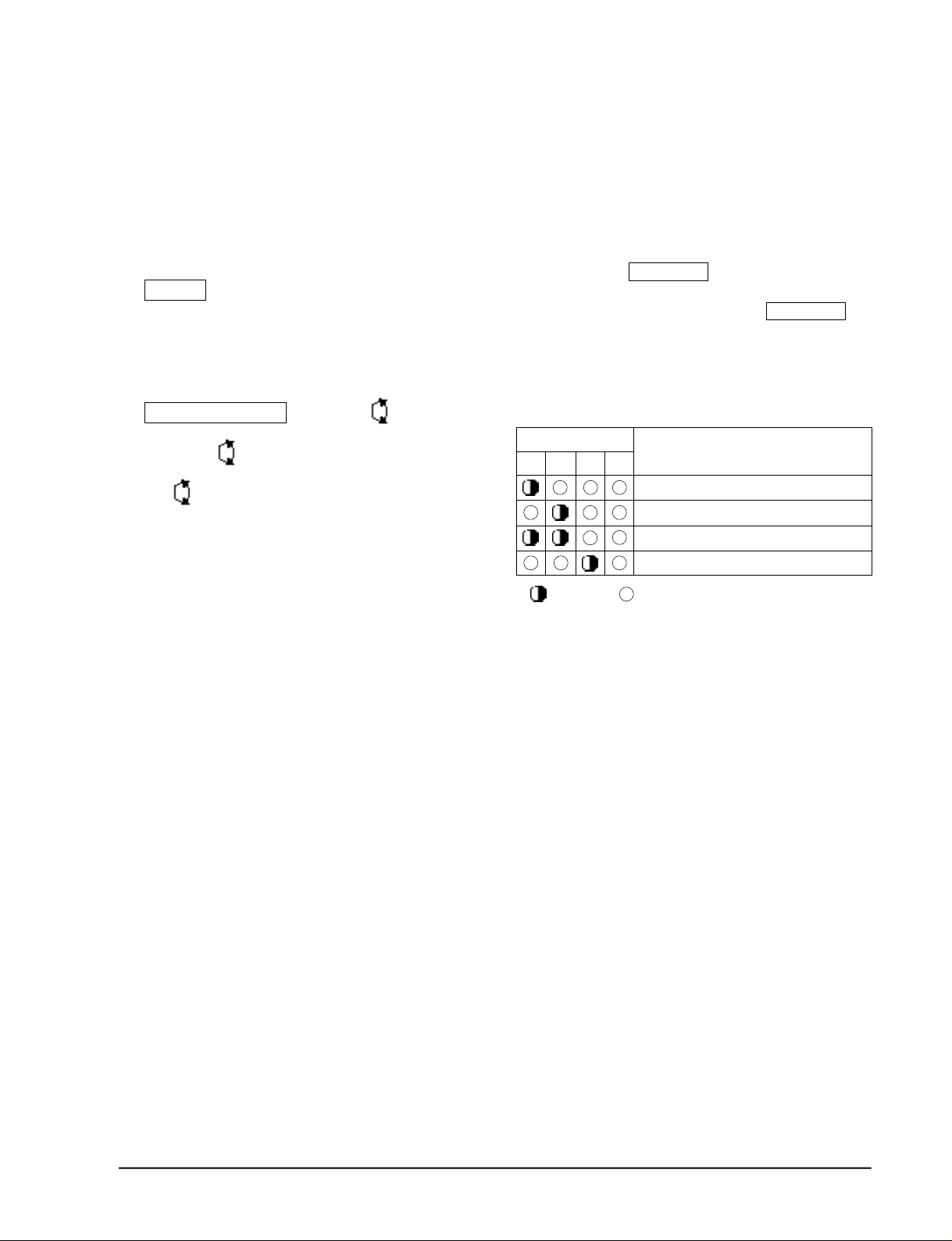
1 2 . SELF Diagnosis
LED DISPLAY
o p e r-
T I M E R
a t i o n
FA N
Tu r b o
Check Point
I n t e r ruption of electric power and Power on.
Abnormal condition of the room sensor.
Abnormal condition of the indoor unit's heat exchanger sensor.
Indoor unit fan motor lock.
L E D
:
b l i n k i n g
: LED off
1 3 . BUZZER SOUND : Whenever the ON/OFF
button is pressed or whenever change
occurs to the condition which is set up or
select, the compulsory operation mode,
buzzer is sounded "beep"
Samsung Electronics
3-3

3-2 Installation
3-2-1 Selecting Area for Installation
Select an area for installation that is suitable
to the customer's needs.
3-2-1(a) Indoor Unit
1 . Make sure that you install the indoor unit in
an area providing good ventilation. It must
not be blocked by an obstacle affecting the
airflow near the air inlet and the air outlet.
2 . Make sure that you install the indoor unit in
an area allowing good air handling and
endurance of vibration of the indoor unit.
3. Make sure that you install the indoor unit in
an area where there is no source of heat or
vapor nearby.
4 . Make sure that you install the indoor unit in
an area from which hot or cool air is spre a d
evenly in a ro o m .
5 . Make sure that you install the indoor unit in
an area away from TVs, audio units, cordless phones, fluorescent lighting fixture s
and other electrical appliances (at least 1
m e t e r ) .
6 . Make sure that you install the indoor unit in
an area which provides easy pipe connection with the outdoor unit, and easy
drainage for condensed water.
(Fix the unit firmly if it is mounted in a
high place.)
3 . Make sure that you install the outdoor unit
in area providing good ventilation and
which is not dusty. It must not be blocked
by any obstacle affecting the airflow near
the air inlet and the air outlet.
4 . Make sure that you install the outdoor unit
in area free from animals or plants.
5 . Make sure that you install the outdoor unit
in area not blocking the traff i c .
6. Make sure that you install the outdoor unit
in area easy to drain condensed water fro m
the indoor unit.
7. Make sure that you install the outdoor unit
in area which provides easy connection
within the maximum allowable length of a
coolant pipe(10 meters).
N o t e
1. Add (18XX:20g, 24XX:30g) of re f r i g e r a n t
(R-22) for every 1 meter if the pipe length
exceeds the standard pipe length of 5 meters.
2. Maintain a height between the indoor and
outdoor units of less than 3 meters.
8 . Make sure that you install the outdoor unit
in an area which is large enough to accommodate the measurements
shown in figure on the next page.
7. Make sure that you install the indoor unit in
an area which is large enough to accomodate the measurements shown in figure on
the next page.
3-2-1(b) Outdoor Unit
1 . Make sure that you install the outdoor unit
in area not exposed to the rain or direct sun
l i g h t .
(Install a separate sunblind if exposed to
d i rect sun light.)
2 . Make sure that you install the outdoor unit
in area allowing good air moment, not
amplifying noise or vibration, especially to
avoid disturbing neighbours.
Caution :
It is harmful to the air conditioner if it is used in the following environments: greasy areas (including areas near machines),
salty areas such as coast areas, areas where sulfuric gas is present such as hot spring areas. Contact your dealer for advice.
3-4
3-2-1(c) Remote Control Unit
1 . Make sure that you install the remote con-
t rol unit in an area free from obstacles such
as curtains etc, which may block signals
f rom the remote control unit.
2. Make sure that you install the remote cont rol unit in an area not exposed to
d i rect sunlight, and where there is no sourc e
of heat.
3. Make sure that you install the remote cont rol unit in an area away from TVs, audio
units, cordless phones, fluorescent lighting
f i x t u res and other electrical appliances (at
least 1 meter).
Samsung Electronics
3-2-2 Installation diagram of indoor unit and outdoor unit
Operating Instructions and Installation
A Indoor unit gas leak test check point
Indoor unit
Piping
1
3
2
Tape vinyl
B Drain hose installation
Cut the piping hole
sloped slightly
5 6
125mm
or more
Piping may be laid to the rear, left,
right or down .
Right
Rear
Down
Rear
Left
125mm or more
1
2
3
4
5
Samsung Electronics
4
10
Piping (Liquid) 1/4" Clamper tube
18K BTU Piping(Gas) 1/2”
24K BTU Piping(Gas) 5/8”
Installation tube Pipe-connection
Vinyl tape Screw
Putty Drain hose
6
7
8
9
10
Remote control
Remote control holder
Installation plate
3-5
Operating Instructions and Installation
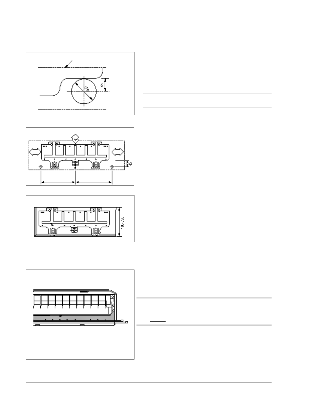
3-2-2(a) Fixing the Installation Plate
(Unit : mm)
(Unit : mm)
Installation plate
512
415
1. Determine the position of the pipe and drain hose hole
using the right figure and drill the hole with an inner
diameter of 65mm so that it slants slightly downwards.
2. If you are fixing the indoor unit to a… Then follow Steps…
Wall 3.
Window frame 4 to 6.
3. Fix the installation plate to the wall in a manner appropriate to the weight of the indoor unit.
227288
If you are mounting the plate on a concrete wall with
anchor bolts, the anchor bolts must not project by more
than 20mm.
4. Determine the positions of the wooden uprights to be
attached to the window frame.
3-2-2(b) Purging the Unit
5. Attach the wooden uprights to the window frame in a
manner appropriate to the weight of the indoor unit.
6. Using tapped screws, attach the installation plate to the
wooden uprights, as illustrated in the last figure opposite.
On delivery, the indoor unit is loaded with an inert gas.
All this gas must therefore be purged before connecting the
assembly piping. To purge the inert gas, proceed as fol lows.
Unscrew the caps at the end of each pipe.
Result : All inert gas escapes from the indoor unit.
• To prevent dirt or foreign objects from getting into
the pipes during installation, do NOT remove the
caps completely until you are ready to connect the
piping.
3-6
Samsung Electronics
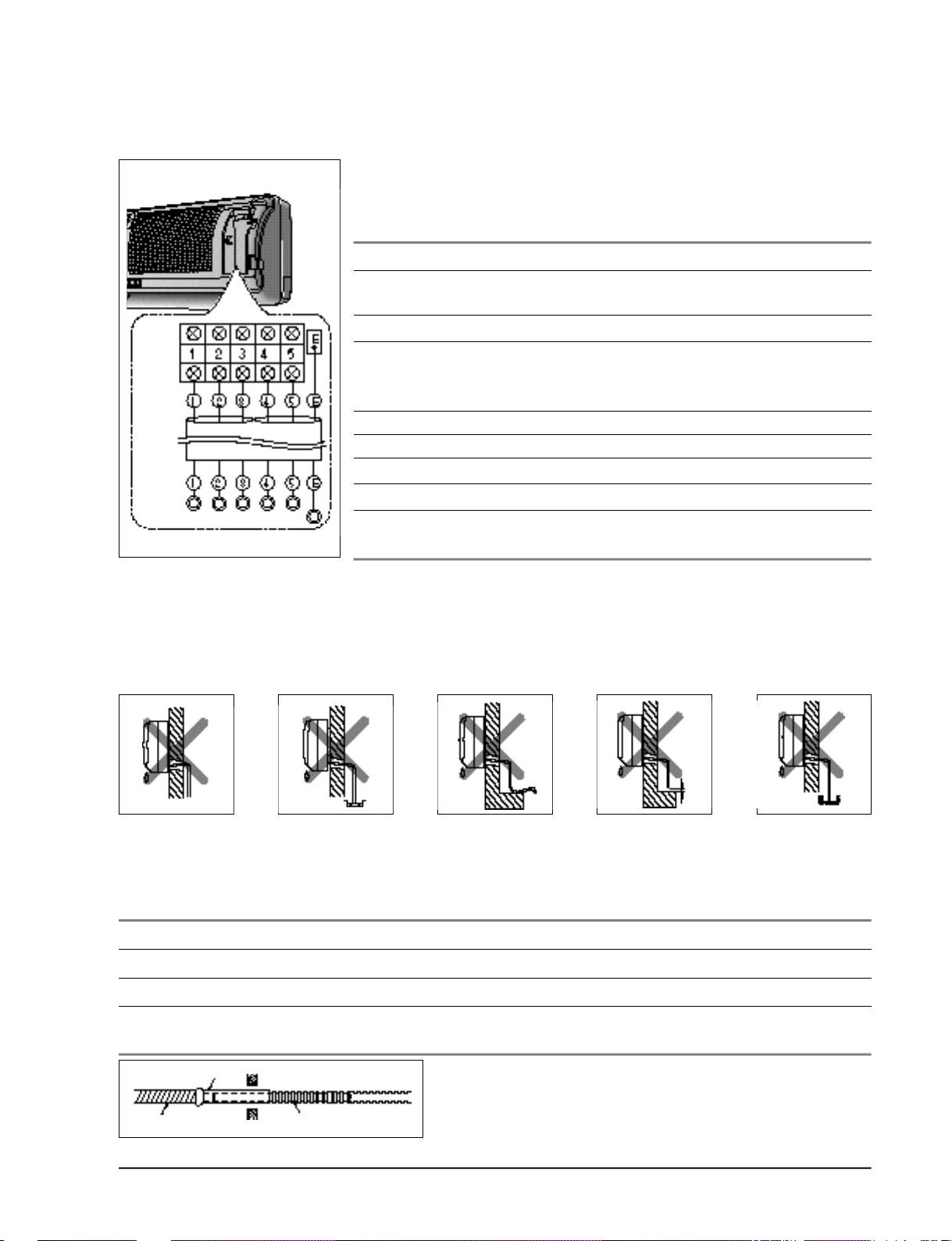
3-2-2(c) Connecting the Assembly Cable.
The indoor unit is powered from the outdoor unit via the assembly
cable. If the outdoor unit is more than five metres away from the
indoor unit, the cable must first be extended to a maximum of 15
m e t re s .
1 . Extend the assembly cable if necessary.
2 . Open the front grille by pulling on the tabs on the lower right and
left sides of the indoor unit.
Indoor
unit
Outdoor
unit
3 . Remove the screw securing the connector cover.
4 . Pass the assembly cable through the rear of the indoor unit and
connect the assembly cable to terminals 1 to 5.
• Each wire is labelled with the corresponding terminal number.
5 . Firmly fix the ass’y cable with clamp wire holder.
6 . Pass the other end of the cable through the 65mm hole in the wall.
7 . Replace the connector cover, carefully tightening the scre w.
8 . Close the front grille.
9 . For further details on how to plug the other end of the assembly
cable into the outdoor unit, refer to page 3-8.
Operating Instructions and
3-2-2(d) Installing and Connecting the Indoor Unit Drain Hose
C a re must be taken when installing the drain hose for the indoor unit to ensure that any condensa tion water is correctly drained outside.l When passing the drain hose through the 65mm hole drilled
in the wall, check that none of the following situations occur.
The hose must
NOT slope upw
ards.
To install the drain hose, proceed as follows.
1. If necessary, connect the 2-metre extension to the drain hose.
2 . If you are using the extension, insulate the inside part of the extension drain hose with a shield.
3. Pass the drain hose under the refrigerant piping, taking care to keep the drain hose tight.
4. Pass the drain hose through the hole in the wall, making sure that it is sloping downwards, as
shown in the illustrations above.
The end of the drain
hose must NOT be
placed in water.
Do NOT bend the
hose in different
directions.
Keep a clearance of at
least 5cm between the
end of the hose and the
ground.
Do NOT place the end
of the drain hose in a
hollow.
Shield
Drain hose Extension drain hose
Samsung Electronics
3-7
 Loading...