

Samsung SGH-D830 Service Manual
GSM TELEPHONE
SGH-D830
GSM TELEPHONE
CONTENTS
1. Safety Precautions
2. Specification
3. Product Function
4. Array course control
5. Exploded View and Parts List
6. MAIN Electrical Parts List
7. Block Diagrams
8. PCB Diagrams
9. Flow Chart of Troubleshooting
10. Reference data

contents
1. Safety Precautions
1-1. Repair Precaution ...........................................................................1-1
1-2. ESD(Electrostatically Sensitive Devices) Precaution ...........................1-2
2. Specification
2-1. GSM General Specification ..............................................................2-1
2-2. GSM Tx Power Class ......................................................................2-2
3. Product Function
3-1. Main Function ................................................................................3-1
4. Array course control
Software Downloading
4-1. Downloading Binary Files ................................................................4-2
4-2. Pre-requsite for Downloading ..........................................................4-2
4-3. S/W Downloader Program ...............................................................4-3
5. Exploded View and Parts List
5-1. Cellular phone Exploded View .........................................................5-1
5-2. Cellular phone Part list ...................................................................5-2
5-3. Disassembly ..................................................................................5-4
5-4. Assembly ......................................................................................5-6
6. MAIN Electrical Pa rts List
7. Block Diagrams
8. PCB Diagrams

contents
9. Flow Chart of Troubleshooting
9-1. Baseband
9-1-1. Power ON .................................................................................9-1
9-1-2. Initial .......................................................................................9-4
9-1-3. Sim Part ...................................................................................9-6
9-1-4. Charging Part ............................................................................9-8
9-1-5. Microphone Part ......................................................................9-10
9-1-6. Speaker Part ...........................................................................9-12
9-1-7. Camera ...................................................................................9-15
9-1-8. LCD ........................................................................................9-17
9-2. RF
9-2-1. GSM Receiver...........................................................................9-19
9-2-2. DCS Receiver............................................................................9-20
9-2-3. PCS Receiver............................................................................9-21
9-2-4. GSM Transmitter.......................................................................9-23
9-2-5. DCS&PCS Transmitter ..............................................................9-24
9-2-7. Bluetooth Part .........................................................................9-27
10. Reference data

1. Safety Precautions
1-1. Repair Precaution
●
Repair in Shield Box, during detailed tuning.
Take specially care of tuning or test,
because specipicty of cellular phone is sensitive for surrounding interference(RF noise).
●
Be careful to use a kind of magnetic object or tool,
because performance of parts is damaged by the influence of manetic force.
●
Surely use a standard screwdriver when you disassemble this product,
otherwise screw will be worn away.
●
Use a thicken twisted wire when you measure level.
A thicken twisted wire has low resistance, therefore error of measurement is few.
●
Repair after separate Test Pack and Set because for short danger (for example an
overcurrent and furious flames of parts etc) when you repair board in condition of
connecting Test Pack and tuning on.
●
Take specially care of soldering, because Land of PCB is small and weak in heat.
●
Surely tune on/off while using AC power plug, because a repair of battery charger is
dangerous when tuning ON/OFF PBA and Connector after disassembing charger.
●
Don't use as you pleases after change other material than replacement registered on SEC
System.
Otherwise engineer in charge isn't charged with problem that you don't keep this rules.
1-1
SAMSUNG Proprietary-Contents may change without notice
This Document can not be used without Samsung's authorization

Safety Precautions
1-2. ESD(Electrostatically Sensitive Devices) Precaution
Several semiconductor may be damaged easilly by static electricity. Such parts are called by
ESD(Electrostatically Sensitive Devices), for e xample IC,BGA chip etc. Read Precaution below.
You can prevent from ESD damage by static electricity.
●
Remove static electricity remained your body before you touch semiconductor or parts with
semiconductor. There are ways that you touch an earthed place or wear static electricity
prevention string on wrist.
●
Use earthed soldering steel when you connect or disconnect ESD.
●
Use soldering removing tool to break static electricity. , otherwise ESD will be damaged by
static electricity.
●
Don't unpack until you set up ESD on product. Because most of ESD are packed by box
and aluminum plate to have conductive power,they are prevented from static electricity.
●
You must maintain electric contact between ESD and place due to be set up until ESD is
connected completely to the proper place or a circuit board.
1-2
SAMSUNG Proprietary-Contents may change without notice
This Document can not be used without Samsung's authorization
2. Specification
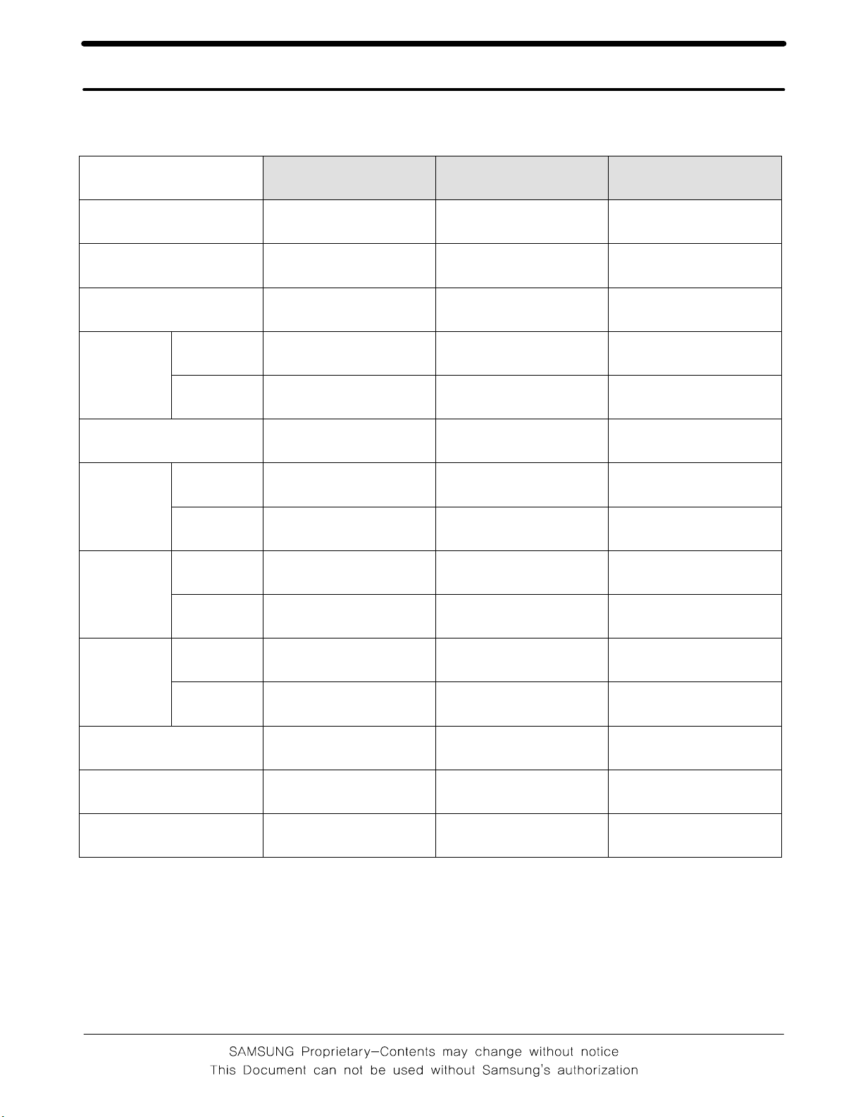
2-1. GSM General Specification
GSM 900
Freq. Band[MHz]
Uplink/Downlink
ARFCN r ange
Tx/Rx spacing 45 MHz 95 MHz 80 MHz
Mod. Bit
rate/
Bit Period
Time Slot
Period/Frame Period
Modulation
MS Power
GPRS
EDGE
GPRS 0.3 GMSK 0.3 GMSK 0.3 GMSK
EDGE 8PSK 8PSK 8PSK
GPRS 33 dBm~5 dBm 30 dBm~0 dBm 30 dBm~0 dBm
EDGE 27~5 dBm 26~0 dBm 26~0 dBm
880~915
925~960
0~124
&975~1023
270.833 Kbps
3.692 us
812.5 Kbps
3.692 us
576.9 us
4.615 ms
DCS1800 PCS1900
1710~1785
1805~1880
512~885 512~810
270.833 Kbps
3.692 us
812.5 Kbps
3.692 us
576.9 us
4.615 ms
270.833 Kbps
1850~1910
1930~1990
3.692 us
812.5 Kbps
3.692 us
576.9 us
4.615 ms
Power
Level
Sensitivity -102 dBm -100 dBm -102 dBm
TDMA Mux 8 8 8
Cell Radius 35 Km 2 Km 2 Km
GPRS 5pcl~19pcl 0pcl~15pcl 0pcl~15pcl
ED G E 8~ 1 9(c l as s E2 ) 2~15(class E2) 2~15(class E2)
2-1
Specification
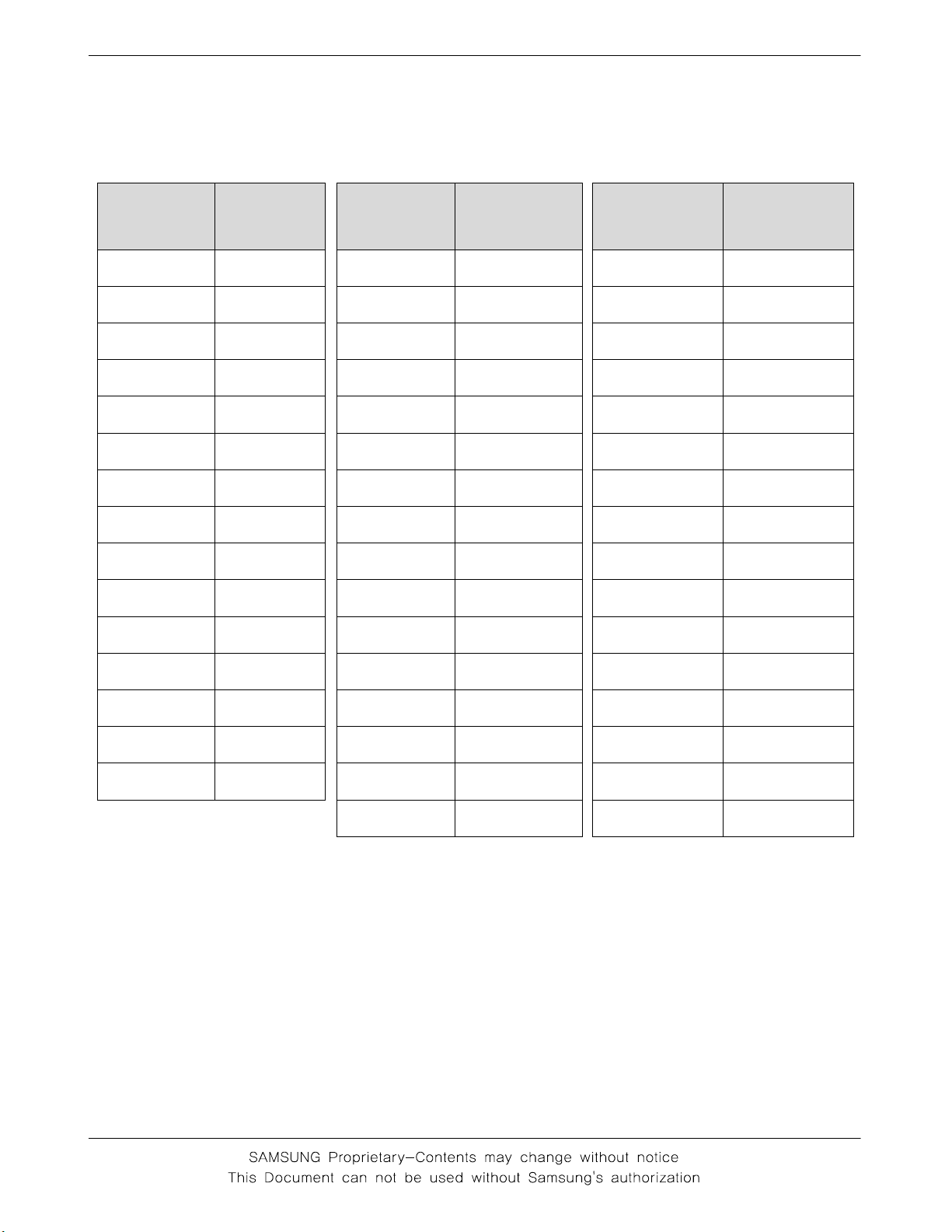
2-2. GMSK TX power Level
TX Power
control
level
5 33±2 dBm
6 31±3 dBm
7 29±3 dBm
8 27±3 dBm
9 25±3 dBm
10 23±3 dBm
11 21±3 dBm
12 19±3 dBm
13 17±3 dBm
14 15±3 dBm
15 13±3 dBm
GSM900
TX Power
control
level
0 30±2 dBm
1 28±3 dBm
2 26±3 dBm
3 24±3 dBm
4 22±3 dBm
5 20±3 dBm
6 18±3 dBm
7 16±3 dBm
8 14±3 dBm
9 12±4 dBm
10 10±4 dBm
DCS1800
TX Power
control
level
0 30±2 dBm
1 28±3 dBm
2 26±3 dBm
3 24±3 dBm
4 22±3 dBm
5 20±3 dBm
6 18±3 dBm
7 16±3 dBm
8 14±3 dBm
9 12±4 dBm
10 10±4 dBm
PCS1900
16 11±5 dBm
17 9±5 dBm
18 7±5 dBm
19 5±5 dBm
11 8±4d Bm
12 6±4 dBm
13 4±4 dBm
14 2±5 dBm
15 0±5 dBm
2-2
11 8±4 dBm
12 6±4 dBm
13 4±4 dBm
14 2±5 dBm
15 0±5 dBm
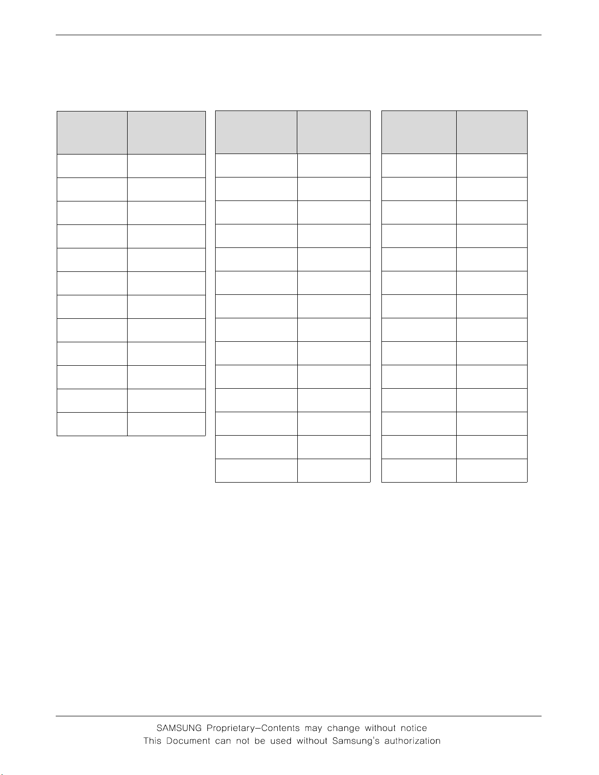
2-3. EDGE TX Power Level
Specification
TX Power
control
GSM850
level
827±3dBm
925±3dBm
10 23±3 dBm
11 21±3 dBm
12 19±3 dBm
13 17±3 dBm
14 15±3 dBm
15 13±3 dBm
16 11±5 dBm
17 9±5 dBm
18 7±5 dBm
TX Power
control
DCS1800
level
226±3dBm
324±3dBm
422±3dBm
520±3dBm
618±3dBm
716±3dBm
814±3dBm
912±4dBm
10 10±4 dBm
11 8±4 dBm
12 6±4 dBm
TX Power
control
PCS1900
level
226±3dBm
324±3dBm
422±3dBm
520±3dBm
618±3dBm
716±3dBm
814±3dBm
912±4dBm
10 10±4 dBm
11 8±4 dBm
12 6±4 dBm
19 5±5 dBm
13 4±4 dBm
14 2±5 dBm
15 0±5 dBm
2-3
13 4±4 dBm
14 2±5 dBm
15 0±5 dBm

3. Product Function
Main Function
-Cameraandcamcorder
- Image editor
-Musicplayer
- Photo printing
- Phone to TV
- File viewer
-Bluetooth
-Webbrowser
- Offline mode
-E-,ail
- Multimedia Message Service (MMS)
-Java
- Voice recorder
3-1
SAMSUNG Proprietary-Contents may change without notice
This Document can not be used without Samsung's authorization
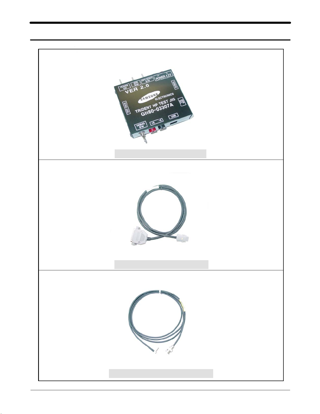
4. Array course control
Test Jig (GH80-03307A)
Test Cable (GH39-00478A)
RF Test Cable (GH39-00599A)
4-1
SAMSUNG Proprietary-Contents may change without notice
This Document can not be used without Samsung's authorization

Array course control
4-1. Downloading Binary Files (1)
•Swift Model firmware is composed of 2 files
–*.s3 : Main source code binary.
4-2. Prerequisite
•Downloader program(Optiflash.exe)
•D830 Moblie Phone
•Data Cable
•Binary Files
4-2
SAMSUNG Proprietary-Contents may change without notice
This Document can not be used without Samsung's authorization

4-3. S/W Downloader Program
1. Load the binary download program by execution the "OptiFlash.exe"
Array course control
2. Select the“Options” -> “Settings” -> “Generic” -> “Specify hardware platform”.
Choose hardware platform for the downloader file setting.
Set the everything else as the default values which are shown below
4-3
SAMSUNG Proprietary-Contents may change without notice
This Document can not be used without Samsung's authorization
Array course control
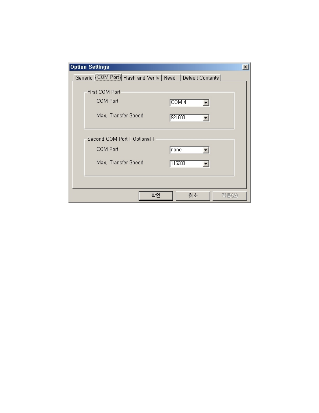
3. Select the COM port where the download cable is connected
Up to twelve ports are supported. Additionally you can select the maximum
transfer speed OptiFlash will use to communicate with the phone. However,
Optiflash will use a slower speed if either the PC’s or the phone’s serial
hardware is incapable of handling the selected speed.
4-4
SAMSUNG Proprietary-Contents may change without notice
This Document can not be used without Samsung's authorization
Array course control
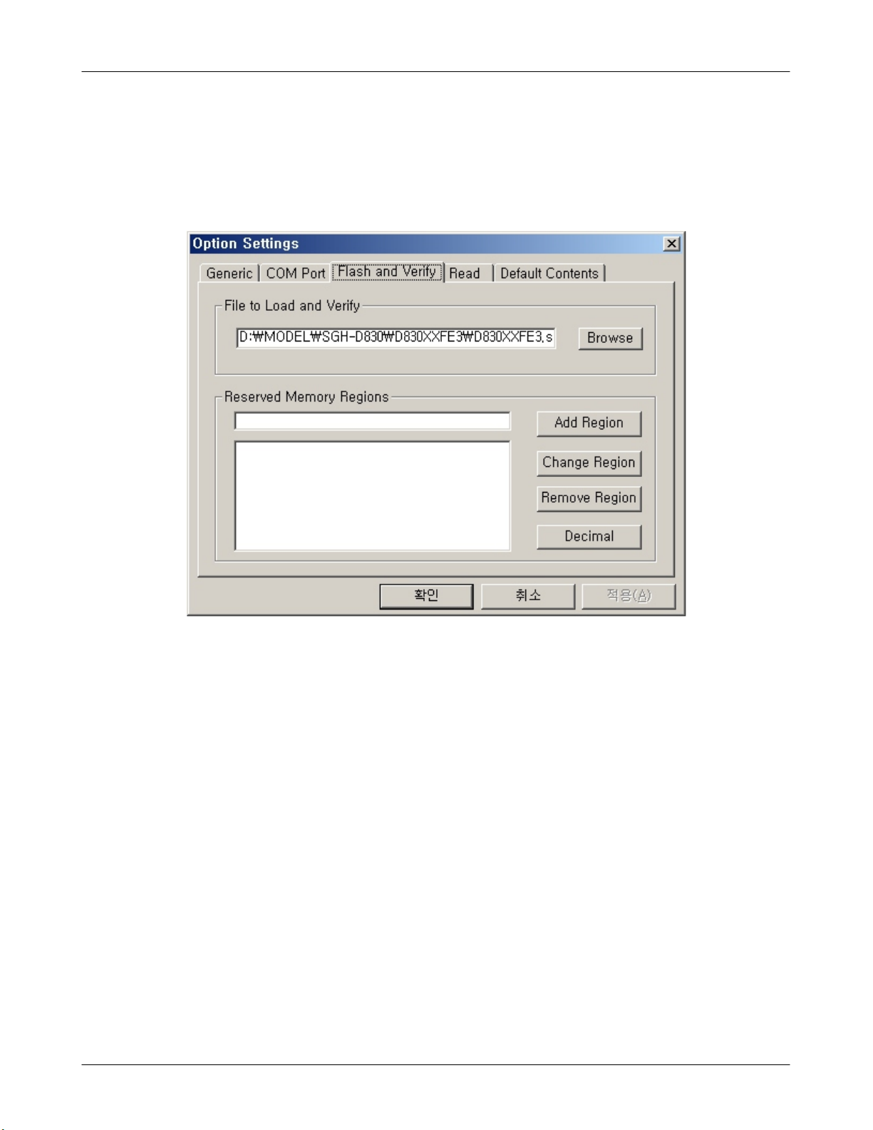
4. Select the “Flash&Verify” -> “Browse”
Set the directory path and choose the latest S/W binary, for example
"D830XXYY.s3", for the downloader binary setting.
4-5
SAMSUNG Proprietary-Contents may change without notice
This Document can not be used without Samsung's authorization
Array course control
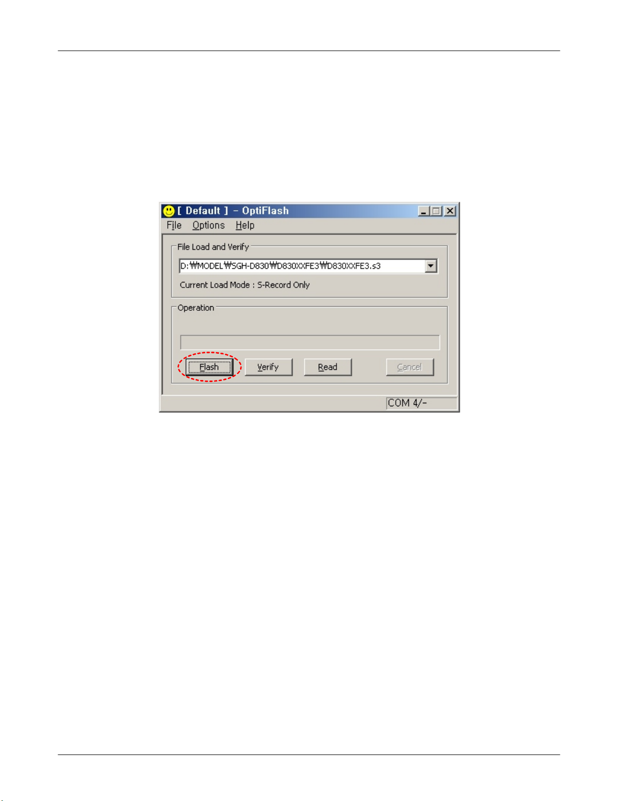
5. Click “OK” button then press “Flash”.
(Before pressing 'Flash' button, push the button '*'and 'END' at the same
time. then press 'Flash'.)
Downloader will upload the binary file as below for the downloading.
6. When downloading is finished successfully, there is a “All is well” message.
7. After finishing downloading, Certain memory resets should be done to
guarantee the normal performance.
8. Confirm the downloaded version name by key-string(*#1234#)
Memory reset will be done by pressing the following key-strings.
Full Reset :“*2767*3855#” will reboot the phone automatically.
4-6
SAMSUNG Proprietary-Contents may change without notice
This Document can not be used without Samsung's authorization
5. Exploded View and Parts List
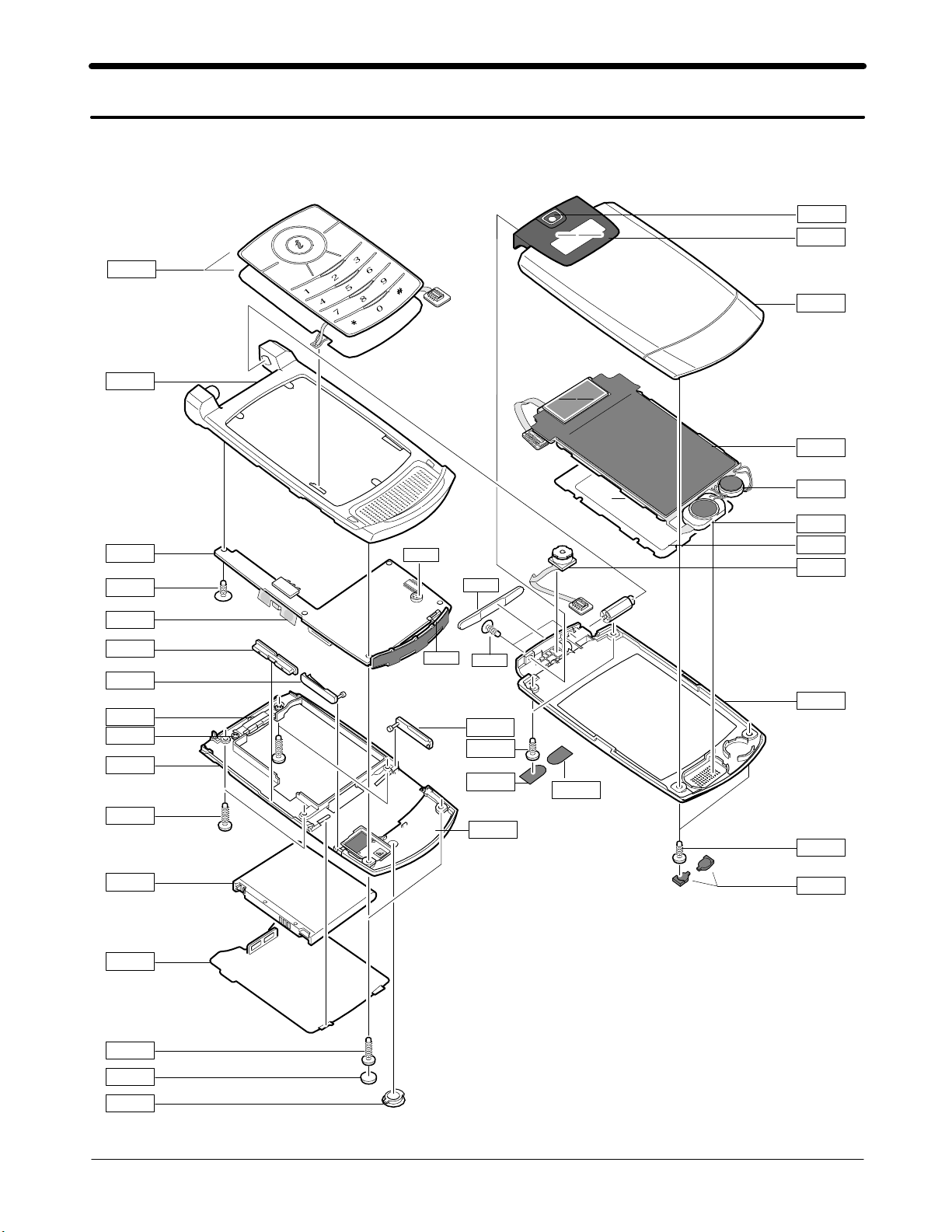
5-1. Cellular phone Exploded View
QKP01
QFR01
QMP01
QCR32
QMI01
QSC01
QCW01
QWD01
QFU01
QLC01
QMO01
QSP01
QMW01
QCA01
QVK01
QVO01
QIF01
QCR32
QCR47
QRE01
QCR05
QBA01
QBA00
QCR05
QSC13
QAN02
QCR47
QRF10
QCR47
QSC03
QRE02
QFL01
QSC02
QCR47
QSC07
QRF01
5-1
SAMSUNG Proprietary-Contents may change without notice
This Document can not be used without Samsung's authorization

Exploded View and Parts List
5-2. Cellular phone Parts list
Design LOC Discription SEC CODE
INTENNA-SGHD830 GH42-00862A
IPR-COVER BATT GH70-01257A
INNER BATTERY PACK-630MAH,BLK, GH43-02386A
UNIT-2M CAMERA GH59-03178A
SCREW-MACHINE 6001-001478
SCREW-MACHINE 6001-001700
SCREW-MACHINE 6001-001695
PMO-COVER CAM WINDOW GH72-30063A
ASSY MEC-COVER F/LOWER SUB GH75-09607A
ASSY MEC-COVER FRONT SUB GH75-09606A
ASSY MEC-COVER F/UPPER GH75-09608A
ASSY KEYPAD-(SER/TK) GH75-09610A
LCD-SGHD830 MODULE GH07-00933A
MICROPHONE-ASSY-SGHD830 GH30-00278A
MOTOR DC-SGHD830 GH31-00254A
PBA MAIN-SGHD830 GH92-02682A
AS-LCD WINDOW GH81-04361A
QAN02
QBA00
QBA01
QCA01
QCR05
QCR32
QCR47
QCW01
QFL01
QFR01
QFU01
QKP01
QLC01
QMI01
QMO01
QMP01
QMW01
QRF01 PMO-COVER RF V2 GH72-32939A
QSC01
QSC02
QSC03
QSC07
QSC13
QSP01
QVK01
QVO01
QWD01
QRE01
ASSY MEC-RUBBER STOPPER GH75-09611A
MPR-TAPE,3.45X5.14X0.26,SHEET GH74-22113A
MPR-TAPE,3.45X5.14X0.27,SHEET GH74-22114A
RMO-COVER LOWER SCREW A V2 GH73-07558A
RMO-COVER REAR SCREW GH73-07559A
SPEAKER 3001-001965
UNIT-VOLUME KEY GH59-03160A
PMO-KEY VOLUME GH72-30056A
PMO-COVER SUB WINDOW GH72-33401A
ASSY MEC-COVER REAR SUB GH75-09609A
QCR32 SCREW-MACHINE 6001-001700
QCR47 SCREW-MACHINE 6001-001695
QIF01 PMO-COVER IF GH72-30054A
QRE02 ASSY-COVER-REAR BOT TOM SUB GH98-01376A
QRF10 PMO-COVER MICRO SD GH72-32061A
5-2
SAMSUNG Proprietary-Contents may change without notice
This Document can not be used without Samsung's authorization

Exploded View and Parts List
Discription SEC CODE
BAG PE 6902-000297
CBF INTERFACE-DATA LINK CABLE GH39-00444A
ADAPTOR-SGHD800 TA(EU) GH44-01060A
S/W CD -SAMSUNG PC STUDIO 3.0 GH46-00267A
UNIT-EARPHONE(BLK) GH59-02499A
LABEL(P)-WATER SOAK GH68-02026A
LABEL(P)-WATER SOAK GH68-02026A
LABEL(P)-WATER SOAK GH68-02026A
MANUAL-WARRANTY CARD GH68-02623A
MANUAL-SFC GH68-04336A
LABEL(P)-BARCODE RUSSIA GH68-08494A
MANUAL USERS-EU RUSSIAN GH68-11437A
LABEL(R)-MAIN(SER) GH68-11753B
BOX(P)-UNIT MAIN(SER) GH69-04197B
CUSHION-CASE-TA2-MA2 GH69-04208A
RMO-CUSHION RUBBER PCB SOLD A GH73-07322A
RMO-CUSHION MIC HOLDER GH73-07324A
RMO-RUBBER PCB B GH73-07822A
RMO-RUBBER FRONT A GH73-07927A
RMO-RUBBER FRONT B GH73-07928A
RMO-RUBBER PCB SOLD AK GH73-07929A
RMO-RUBBER PCB SOLD CSP GH73-07930A
MPR-BOHO VINYL LCD CONN GH74-15350A
MPR-TAPE PCB KET CON GH74-24316A
MPR-TAPE MAIN WINDOW GH74-24396A
MPR-SPONGE PCB COMP GH74-25365A
MPR-VINYL BOHO MAIN WINDOW GH74-25366A
MPR-TAPE LCD CONN GH74-25810A
MPR-VINYL BOHO SUB WINDOW GH74-26198A
MPR-SPONGE REAR BOTTOM GH74-26376A
AS-LCD SUB GH81-04360A
AS-LCD MAIN GH81-04362A
AS-LCD TAPE GH81-05011A
5-3
SAMSUNG Proprietary-Contents may change without notice
This Document can not be used without Samsung's authorization
Disassembly and Assembly instructions
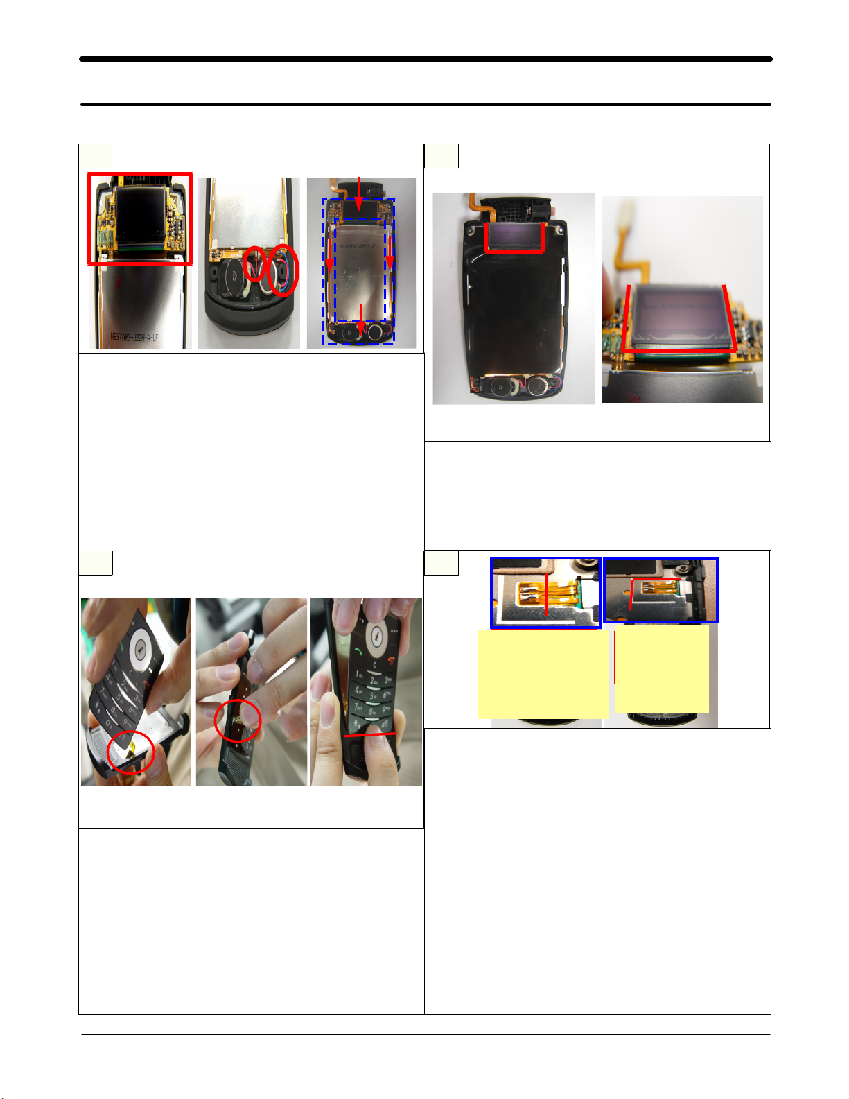
5-3. Disassembly
1.Attach the SUB LCD first on the LOWER.
2.Press the WIRE with a finger not to remain
it on the SPEAKER/MOTOR and fixtures.
3.Remain the MOTOER WIRE exactly between
SCREW BOSS and a fixture.
caution
1) Do NOT remain the WIRE on the RIB.
Press the LCD to attach well on the LOWER.
(Do NOT OVERPOWER Pressing the SUB LCD.)
1.Attach a black LCD ESD TAPE along by the
SUB LCD outline.
caution
1) Press the LCD well NOT to get loose.(Do
NOT OVERPOWER Pressing the SUB LCD.)
1.Insert EL KEYPAD FPCB into the EL KEYPAD
HOLE of the FRONT.
2.Insert a point of EL KEYPAD contact into
the HOLE of the FRONT.
3.Attach the EL KEYPAD along by the end of
EL KEYPAD GUIDE LINE of the Front
caution
1) Be careful NOT TO DAMAGE the EL KEYPAD
FPCB.
Do NOT OVERPOWER attaching the EL
KEYPAD.
SAMSUNG Proprietary-Contents may change without notice
This Document can not be used without Samsung's authorization
Attach the EL KEYPAD
contact point FPCB to
the end of left side of
REAR double sided
tape.
Attach the
green tape
along by the
base line.
1.Remove the exfoliation paper of the double
sided TAPE of the REAR.
2.Remove the exfoliation paper of the double
sided TAPE of the EL KEYPAD CONTACT
POINT.
3.Attach the EL KEYPAD contact point FPCB
along by the base line.
4.Attach a green tape. (the width to the end
of GASKET, the length to the SUS HOLE of
REAR)
caution
1) Be careful NOT TO DAMAGE the EL KEYPAD
FPCB.
Be careful NOT TO ATTACH the green tape on
the GASKET.
Do NOT FOLDER the EL KEYPAD contact point
FPBC by constraint.
5-4
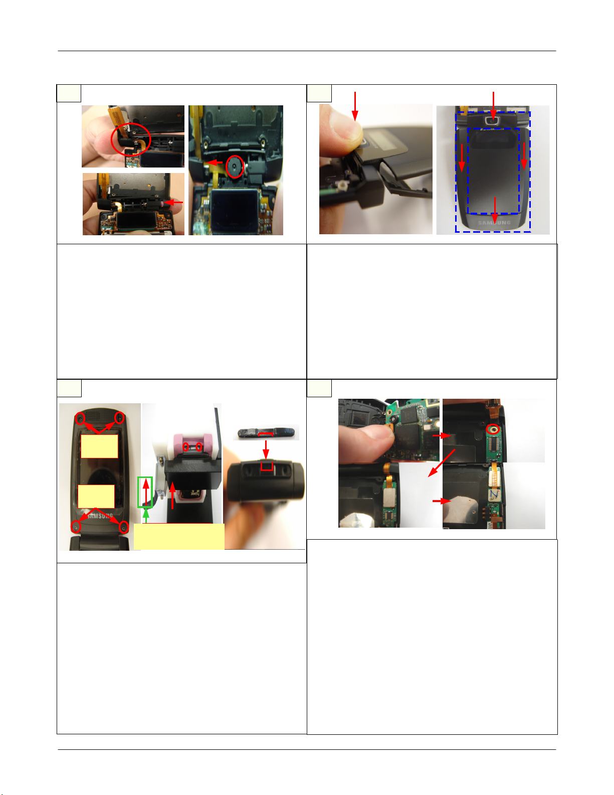
Disassembly and Assembly instructions
1.Insert LCD FPCB into HINGE DUMMY.
2.Assemble the LOWER with FRONT by
Pressing the HINGE insertion part.
3.Insert CAMERA FPCB into FRONT HINGE
DUMMY.
4.Set the CAMERA on the camera position of
the LOWER.
caution
1) Be careful NOT TO TEAR the LCD
FPCB/CAMERA FPCB inserting into the
FRONT HINGE DUMMY.
1.Assemble the top part of FOLDER UPPER to
the LOWER exactly.
2.Press the UPPER firmly to assemble well as
the right picture.
3.Check the upper and lower's locking.
caution
1) Do NOT OVERPOWER when the LOCKING is
difficult.
Reassemble after disassembling and
checking each part when the LOCKING is
not good.
Release the lever
after screwing
1.Screw 4POINTs of the Folder.
2.SCREW RUBBER(2POINT) to top,
SCREW SHEET(2POINT) to bottom.
3.Set the FOLDR ASS'Y to HINGE SCREW JIG.
4.Push the lever to lock completely.
5.Release the lever after screwing SCREW
2POINT.
6.Attach the RUBBER's intaglio to the HINGE's
center embossed part.
caution
1) PRESS the upper of HINGE firmly when
screwing HINGE SCREW 2POINTs.
Check the handset if there is any rising
and gap.
1.Connect the EL KEYPAD CONNECTOR to PBA
firmly with a ticking.
2.Set the PBA on the FRONT.
3.Assemble the VOLUME KEY FPCB to FRONT.
4.Screw 1 POINT of PBA's top part.
5.Connect the LCD CONNECTOR firmly with a
ticking.
6.Connect the CAMERA CONNECTOR firmly
with a ticking.
caution
1) Be careful NOT TO TEAR the EL SHEET
FPCB.
Do NOT PRESS T-FLASH CARD SOCKET
with fingers when connecting the EL
KEYPAD FPCB CONNECTOR.
5-5
SAMSUNG Proprietary-Contents may change without notice
This Document can not be used without Samsung's authorization
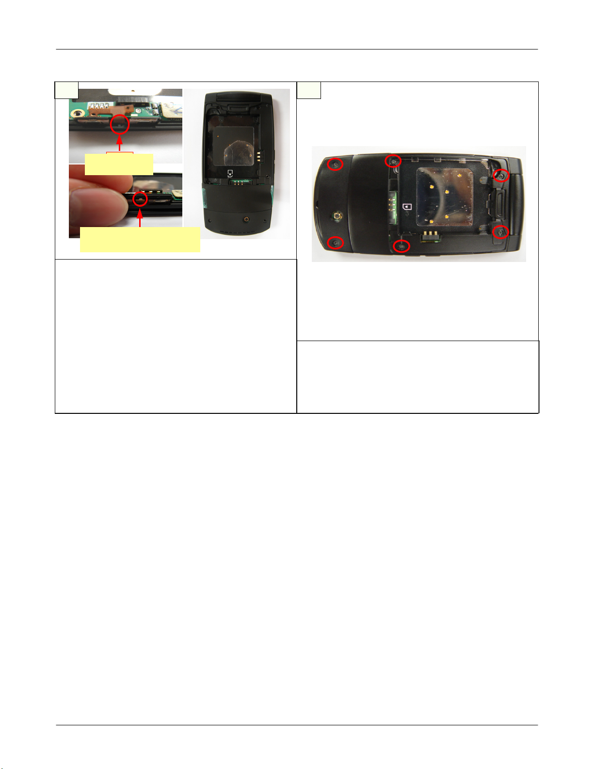
Disassembly and Assembly instructions
check
the rib
check the opening of
KEY FPCB
1.Set VOLUME KEY FPCBto the Rib of FRONT
side by side.
2.Assemble the VOLUME KEY's opening to
FRONT's rising exactly.
3.Assemble the REAR top parts to FRONT top
parts exactly.
4.Assemble not to remove T-FLASH COVER/IF
COVER/VOLUME KEY.
caution
1) Check turning upside down of the VOLUME
KEY .
Check the remaining of T-FLASH COVER/IF
COVER/VOLUME KEY.
1.Check the SET assembly and t he GAP.
2.Set on the SCREW JIG.
3.Screw 6 POINTs of the REAR.
caution
1) Be careful NOT TO SCRATCH the outward
appearance.
5-6
SAMSUNG Proprietary-Contents may change without notice
This Document can not be used without Samsung's authorization
 Loading...