

Page 1
4. Troubleshooting
4-1. Troubleshooting
4-1-1. Previous Check
Check the various cable connections rst.1.
Check to see if there is a burnt or damaged cable. -
Check to see if there is a disconnected or loose cable connection. -
Check to see if the cables are connected according to the connection diagram. -
Check the power input to the Main Board.2.
4. Troubleshooting
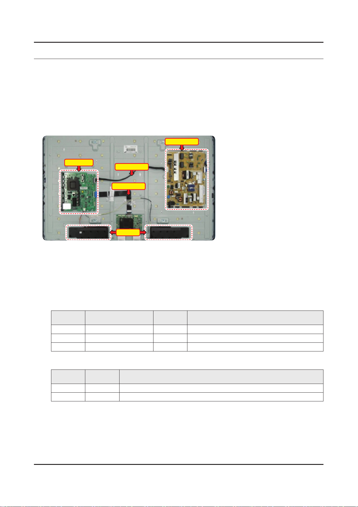
Power Board
Main Board
How to distinguish if the problem is caused by 3. Main Board or T CON
No Video -
If the problem is No Video but BLU is on and Indication LED is blinking repeatedly and faster than nomal booting,
replace the T-CON board.
Distorted Picture -
Check the inner patterns.
For All mode•
X12 FOX_FT1 FRC Post Picture Problem
OK OK NG Main Board or Signal Source
NG OK NG Main Board
NG NG NG Main Board or LVDS cable or T CON or Panel
Power Cable
LVDS Cable
Speaker
Only for HDMI mode (additional check)•
HDMI Picture Problem
OK NG There is no problems after HDMI IC check HDMI source or HDMI jack.
NG NG There is no problems before HDMI IC check X10+ pattern or LVDS cable or T CON
4-1
Page 2
4-2
4. Troubleshooting
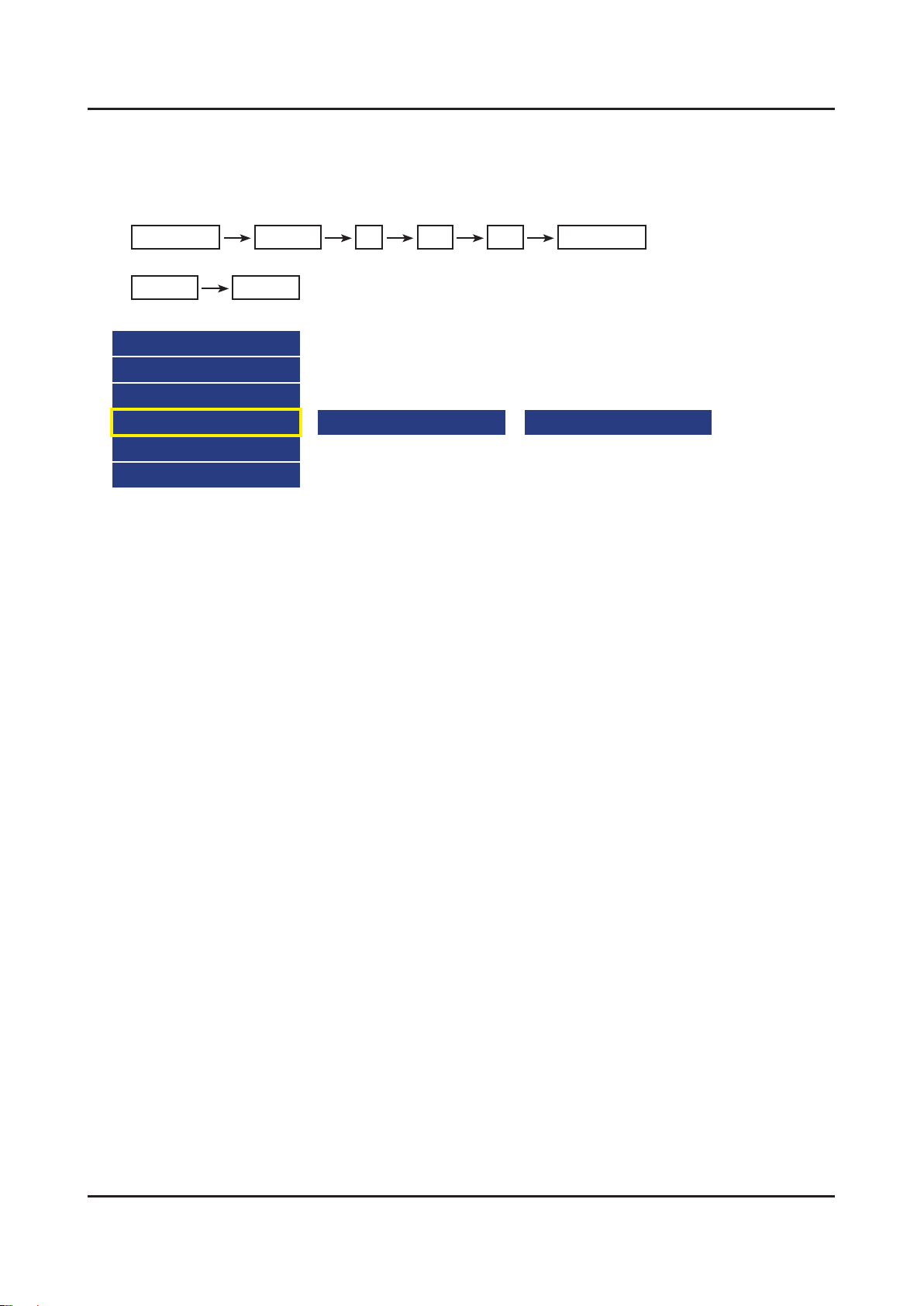
How to check inner pattern?
Enter the service mode 1. ⇢ Choose ‘SVC’ ⇢ Check the ‘internal pattern.’
Enter ‘Service Mode.’2.
If you do not have Factory remote control -
Power OFF MENU 1 8 2 Power On
If you have Factory remote control -
INFO Factory
Choose ‘SVC 3. ⇢ Test pattern’.
Option
Control
Debug
SVC
ADC/WB
Advanced
Check inner patterns.4.
Test Pattern Mstar Test Pattern
Page 3
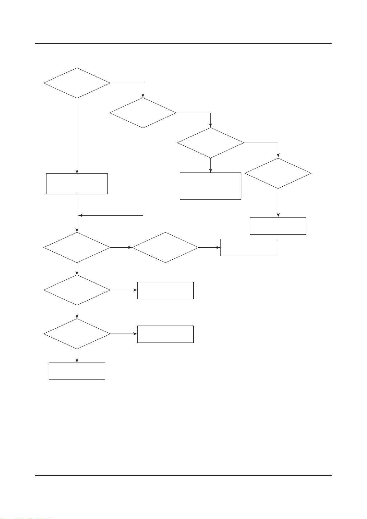
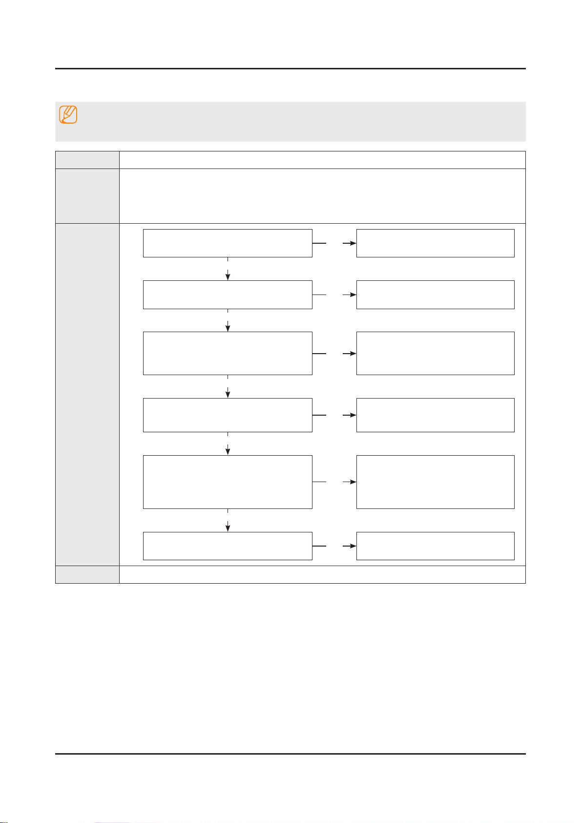
4-1-2. Simple ow chart of malfunction
4-3
4. Troubleshooting
Does the TV turn on?
No
Check the Power Cord.
Yes
Is any sound of
TV when RF signal
connected?
No
Yes
Can you see anything
on the screen?
No
Yes
If necessary replace the
Yes
Check the LVDS
Cable connected.
T-CON Board.
Can you see
OSD menu running
on the screen?
No
Check LVDS cable
connected to Main Board.
If necessary, replace the
Main Board.
No
Change the Main Board.
Yes
Can you see Digital
Channel broadcast ?
No
Replace the Main Board.
A5V appear at
the pin 4 of CN201?
Yes
B13V appear at
the pin 11, 12, 13 of
CN201?
Yes
Please, contact Tech
support.
No
No
Check 28p Cable.
If necessary, replace the
SMPS Board.
Change the Main Board.
Page 4
4-4
4. Troubleshooting
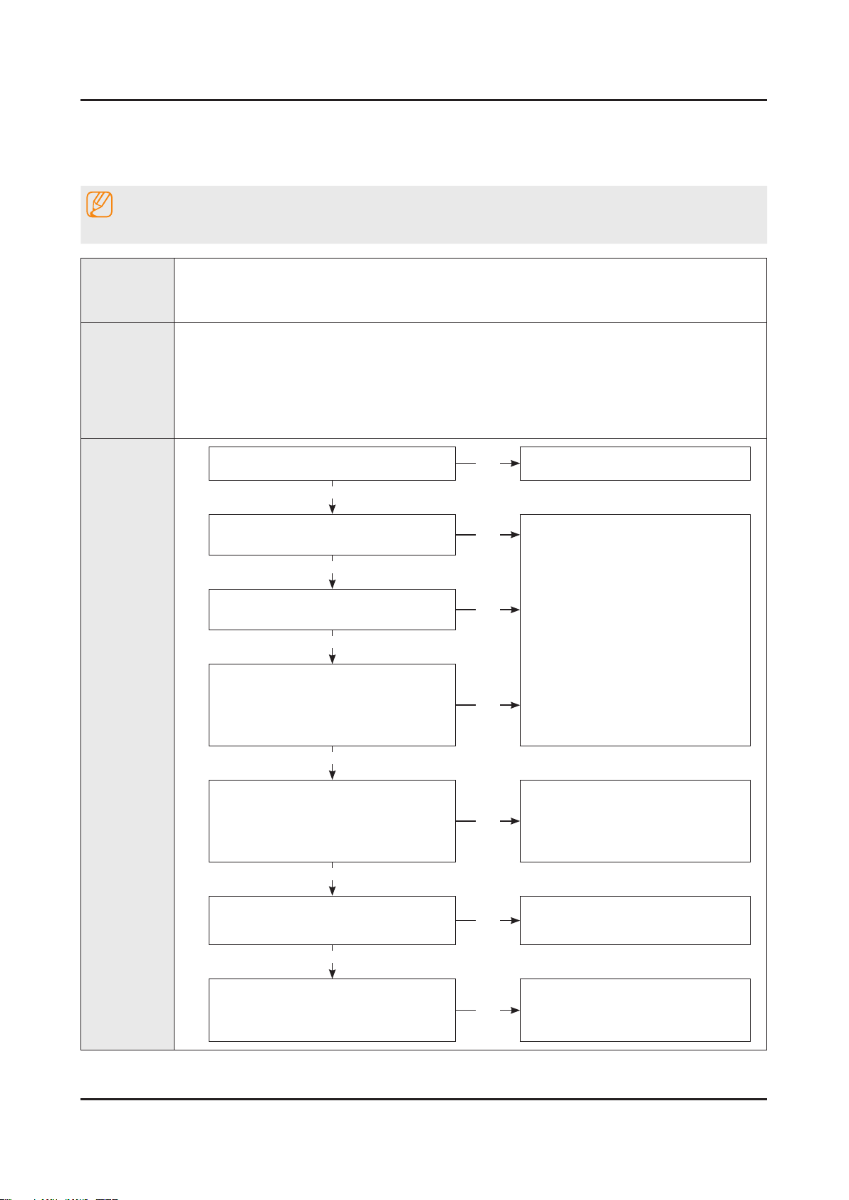
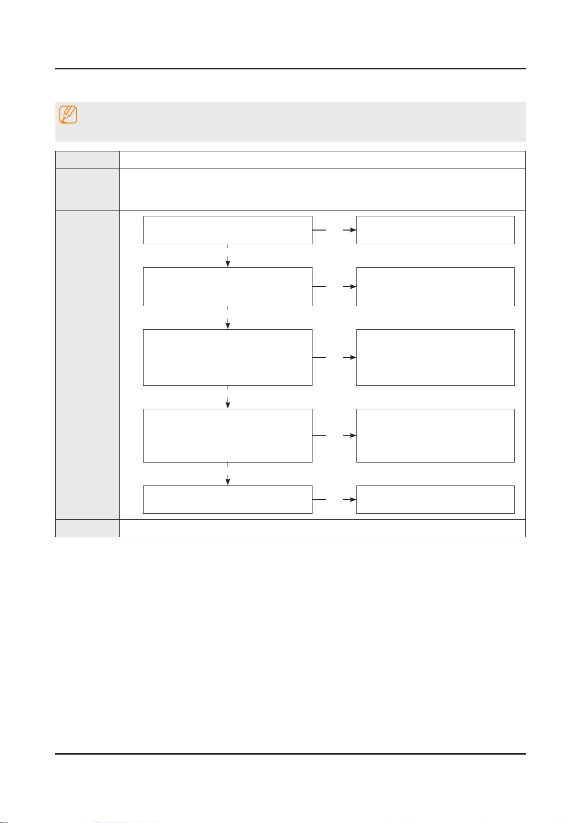
4-2. How to Check Fault Symptom
4-2-1. NO Power
Note
Refer to the next page to check the location such a CN201 or IC201 SVC Manual mentioned.
The LEDs on The front panel do not work when connecting The power cord.•
Symptom
Major
checkpoints
The SMPS relay does not work when connecting The power cord.•
The units appears to be dead.•
The IP relay or the LEDs on the front panel does not work when connecting the power cord if the cables are improperly
connected or the Main Board or SMPS is not functioning. In this case, check the following:
Check the internal cable connection status inside the unit.•
Check the fuses of each part.•
Check the output voltage of SMPS.•
Replace the Main Board.•
Diagnostics
Power indicator LED is on?
Yes
Check the backlight on, when 20 PIN
cable unconnected ?
Yes
Check ‘Stand-By 5V’ ?
BD207 : A5.3V
Yes
Check ‘Power input of Main Ass’y’ ?
BD206 / BD201 : B12VS -
BD214 / 209 : B13V -
BD208 / BD213 : B5V -
Yes
Check ‘Power IC output of Main Ass’y’ ?
IC202 : A3.3V -
L202 : B1.15V / L201 : B5V -
L203 : B3.3V / BD211 : B1.5V -
Yes
No
No
No
No
No
Check the power cord connection.
Change 20p cable.
Change Main Power Ass’y.
Change the Main Ass’y.
Check Input power of ‘T CON Board’ ?
F1(T CON) : B13V -
Yes
Check Power of ‘T CON Board’.
BD1(T CON) : Panel_12V -
B1.1V(T CON-TP) : FT1_1.1V_PW -
No
No
Reconnect or Change.
the LVDS cable.
Change the T CON Board.
Page 5
Yes
4-5
4. Troubleshooting
Diagnostics
Please, Contact tech support.
Caution Make sure to disconnect the power before working on the IP Board.
Page 6
4-6
4. Troubleshooting
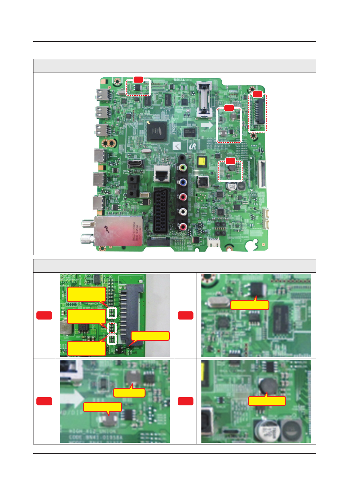
Location of Parts
Main Board_Front
B
A
C
D
Detail
BD214 : B13V
BD209 : B13V
BD211 : B1.5V
A
C
BD206 : B12V
BD201 : B12V
BD213 : B5.3V
BD208 : B5.3V
L202 : B1.15V
BD207 : A5.3V
L201 : B5V
B
D
L203 : B3.3V
Page 7
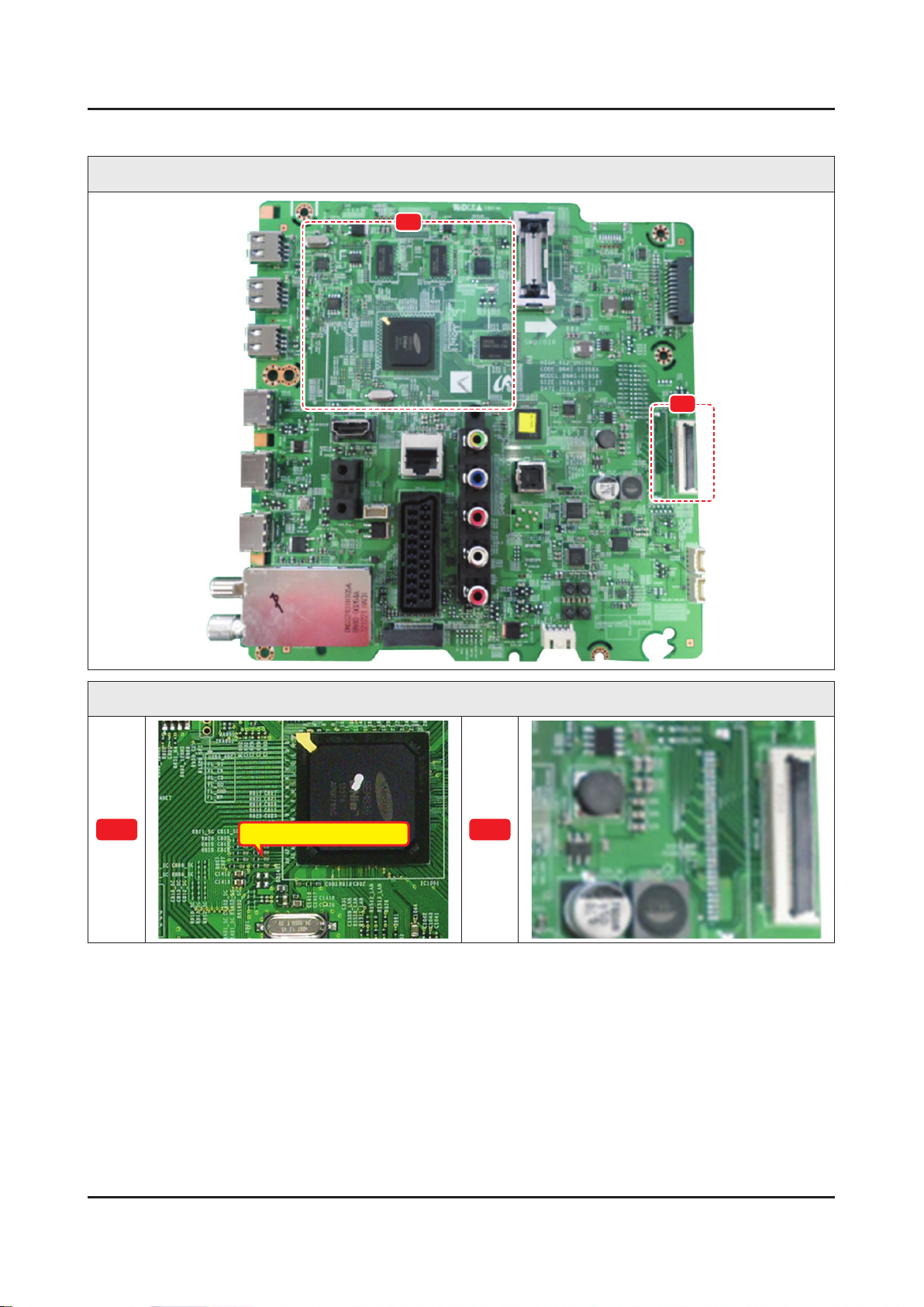
4-2-2. No Video (HDMI 1, 2, 3, 4 - Digital Signal)
4-7
4. Troubleshooting
Note
Refer to the next page to check the location such a CN201 or IC201 SVC Manual mentioned.
Symptom Audio is normal but no picture is displayed on the screen.•
Check the HDMI source.•
Major
checkpoints
Check the HDMI switch.•
This may happen when the LVDS cable connecting the Main Board and the Panel is •
disconnected.
Diagnostics
Power indicator LED is off.
Lamp(Backlight) on, no video ?
Yes
Check the HDMI source and check the
connection of HDMI cable ?
Yes
Check the signal at Input of Main Board ?
1
HDMI1 Clk -
Pin #10, #12 of CN602_H2
DATA •
Pin #7, #9, #4, #6, #1, #3 of
CN602_H2
HDMI2 Clk -
Pin #10, #12 of CN603_H3
DATA •
Pin #7, #9, #4, #6, #1, #3 of
CN603_H3
HDMI3 Clk -
Pin #10, #12 of CN604_H4
DATA •
Pin #7, #9, #4, #6, #1, #3 of
CN604_H4
HDMI4 Clk -
Pin #10, #12 of CN601_H1
DATA •
Pin #7, #9, #4, #6, #1, #3 of
CN601_H1
No
No
No
Check a set in the ‘Stand-by mode’.
Input the HDMI signal properly.
Check CN601~4.
Check HDMI cable.
Change the Main Ass’y.
or
Check IC1001(X12).
Change the Main Ass’y.
Yes
Check the LVDS clk signal at output of
2
Replace the T CON / LCD panel?
Caution Make sure to disconnect the power before working on the IP Board.
Main Board. (TX)
TX2_CLK : ODD_TXCLK_DN/DP -
TX4_CLK : EVEN_TXCLK_DN/DP -
Yes
Check the LVDS cable?
No
No
Please, Contact tech support.
Check IC1001(X12).
Change the Main Ass’y.
Page 8
4-8
4. Troubleshooting
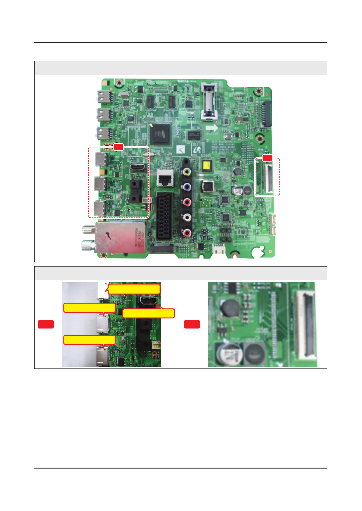
Location of Parts
Main Board_Front
A
B
Detail
CN604_H4 : HDMI3
CN603_H3 : HDMI2
A
CN602_H2 : HDMI1
CN601_H1 : HDMI4
B
Page 9
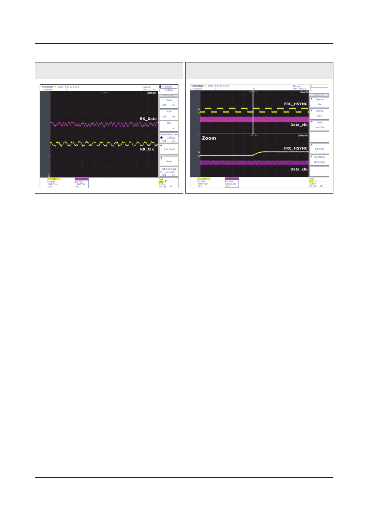
4-9
4. Troubleshooting
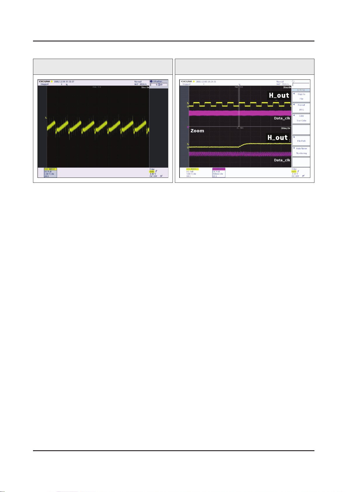
Waveforms
1 HDMI input (RX_Data, RX_Clk) 2 LVDS output
Page 10
4-10
4. Troubleshooting
4-2-3. No Video (Tuner_CVBS)
Note
Refer to the next page to check the location such a CN201 or IC201 SVC Manual mentioned.
Symptom Audio is normal but no picture is displayed on the screen.•
Check the Tuner CVBS source.•
Major
checkpoints
Check the Tuner.•
This may happen when the LVDS cable connecting the Main Board and the Panel is •
disconnected.
Diagnostics
Power indicator LED is off.
Lamp(Backlight) on, no video ?
Yes
Check the RF source and check the
connection of RF cable.
Yes
Check the Power of Tuner ?
1
2
2
Pin #4 of Tuner : B3.3V_Tuner -
Pin #1 of Tuner : B1.8V_Tuner -
Yes
Check the CVBS data out of IC1001 ?
C807 : Tuner CVBS
Yes
Check the LVDS clk signal at output of
Main board. (TX)
TX2_CLK : ODD_TXCLK_DN/DP -
TX4_CLK : EVEN_TXCLK_DN/DP -
Yes
No
No
No
No
No
Check a set in the ‘Stand-by mode’.
Input the RF source properly.
Change the Main Ass’y.
Check IC1001(X12).
Change the Main Ass’y.
Check IC1001(X12).
Change the Main Ass’y.
Check the LVDS cable?
Replace the T CON / LCD panel?
Caution Make sure to disconnect the power before working on the IP Board.
No
Please, Contact tech support.
Page 11
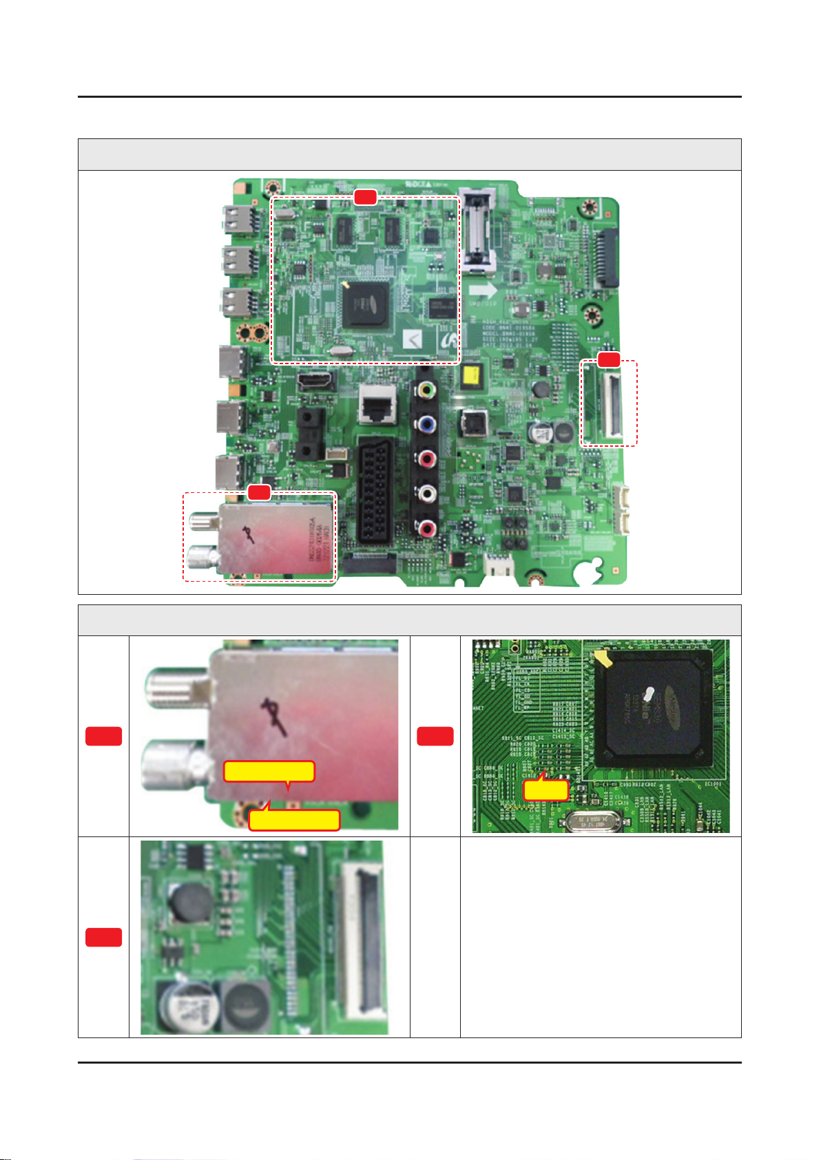
4-11
4. Troubleshooting
Location of Parts
Main Board_Front
B
C
A
Detail
A
Pin #4 : B3.3V
Pin #1 : B1.8V
B
C807
C
Page 12
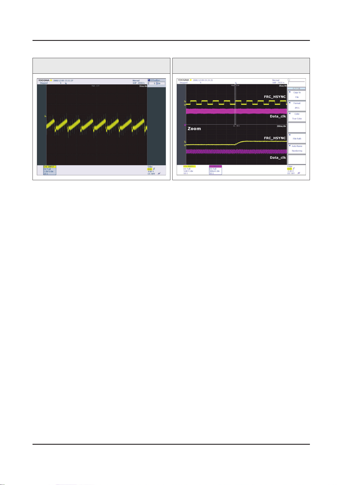
4-12
4. Troubleshooting
Waveforms
1 CVBS OUT (Grey Bar) 2 LVDS output
Page 13
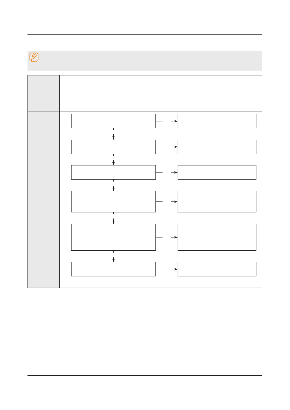
4-2-4. No Vido (Tuner DTV)
4-13
4. Troubleshooting
Note
Refer to the next page to check the location such a CN201 or IC201 SVC Manual mentioned.
Symptom Audio is normal but no picture is displayed on the screen.•
Check the DTV source.•
Major
checkpoints
Check the Tuner.•
This may happen when the LVDS cable connecting the Main Board and the Panel is •
disconnected.
Diagnostics
Power indicator LED is off.
Lamp(Backlight) on, no video ?
Yes
Check the RF source and check the
connection of RF cable.
Yes
1
2
2
Check the ‘signal strength’ in Self
Diagnosis menu Strength is enough ?
Yes
Check the Power of Tuner ?
Pin #4 of Tuner : B3.3V_Tuner -
Pin #1 of Tuner : B1.8V_Tuner -
Yes
Check the LVDS clk signal at output of
Main board. (TX)
TX2_CLK : ODD_TXCLK_DN/DP -
TX4_CLK : EVEN_TXCLK_DN/DP -
Yes
No
No
No
No
No
Check a set in the ‘Stand-by mode’.
Input the RF source properly.
Check the D-TV source.
Change the Main Ass’y.
Check IC1001(X12)
Change the Main Ass’y.
Check the LVDS cable?
Replace the T CON / LCD panel?
Caution Make sure to disconnect the power before working on the IP Board.
No
Please, Contact tech support.
Page 14
4-14
4. Troubleshooting
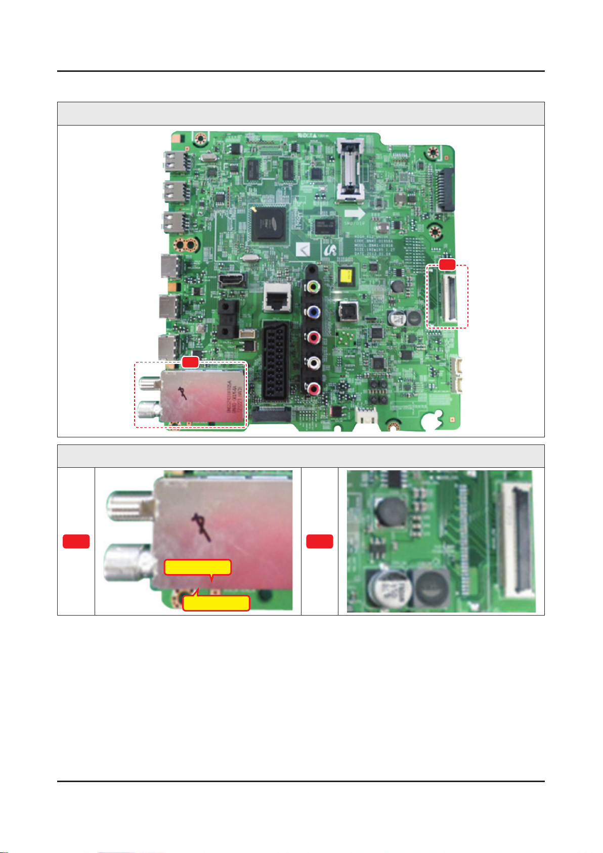
Location of Parts
Main Board_Front
B
A
Detail
A
Pin #4 : B3.3V
Pin #1 : B1.8V
B
Page 15
4-15
4. Troubleshooting
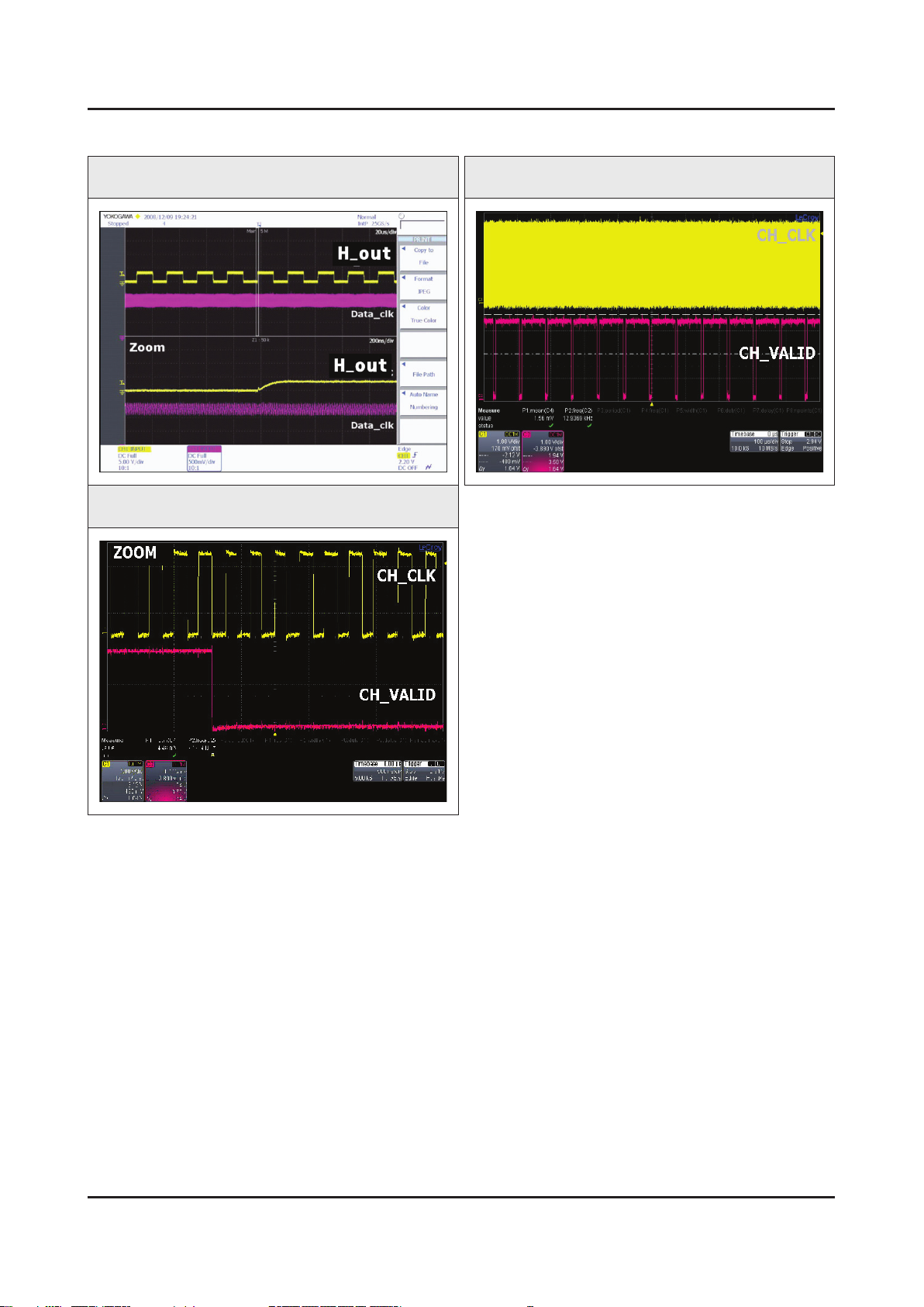
Waveforms
1 CVBS OUT (Grey Bar) 2 CH_CLK, CH_VALID
2 CH_CLK, CH_VALID
Page 16
4-16
4. Troubleshooting
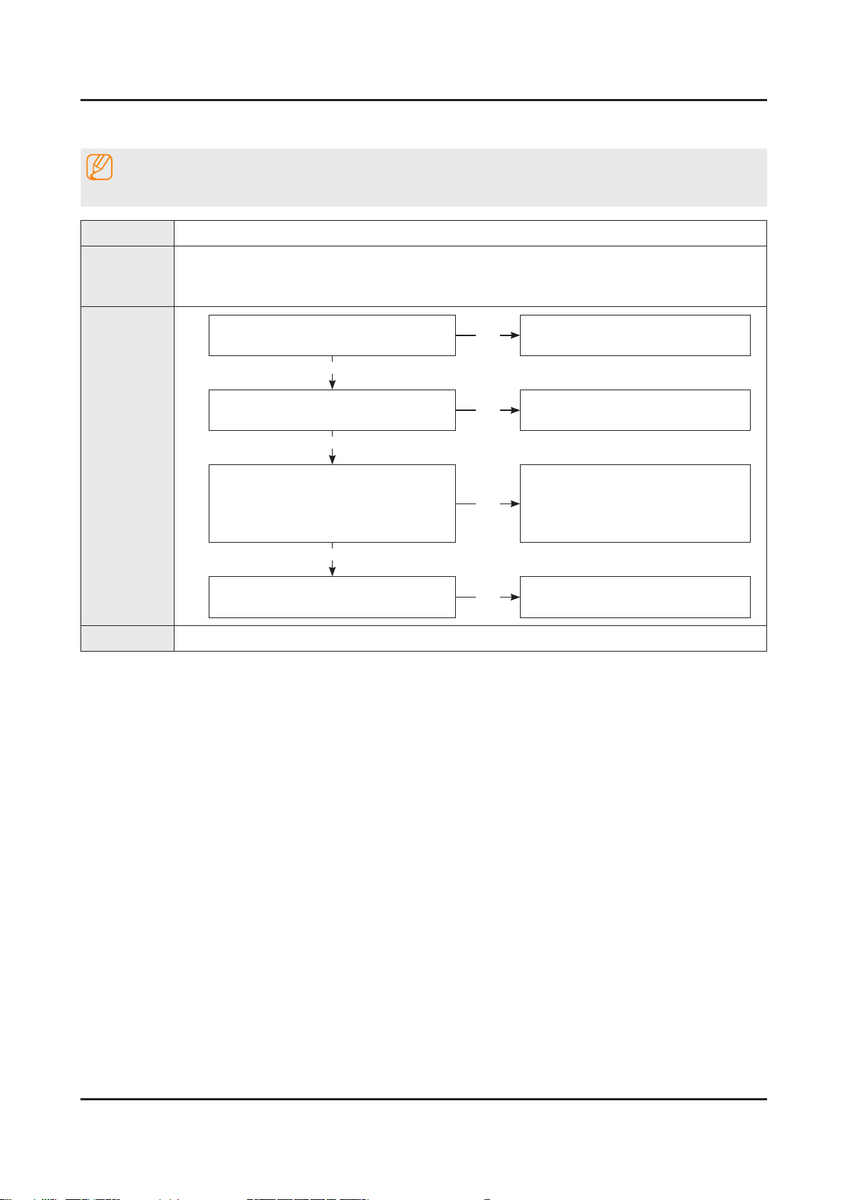
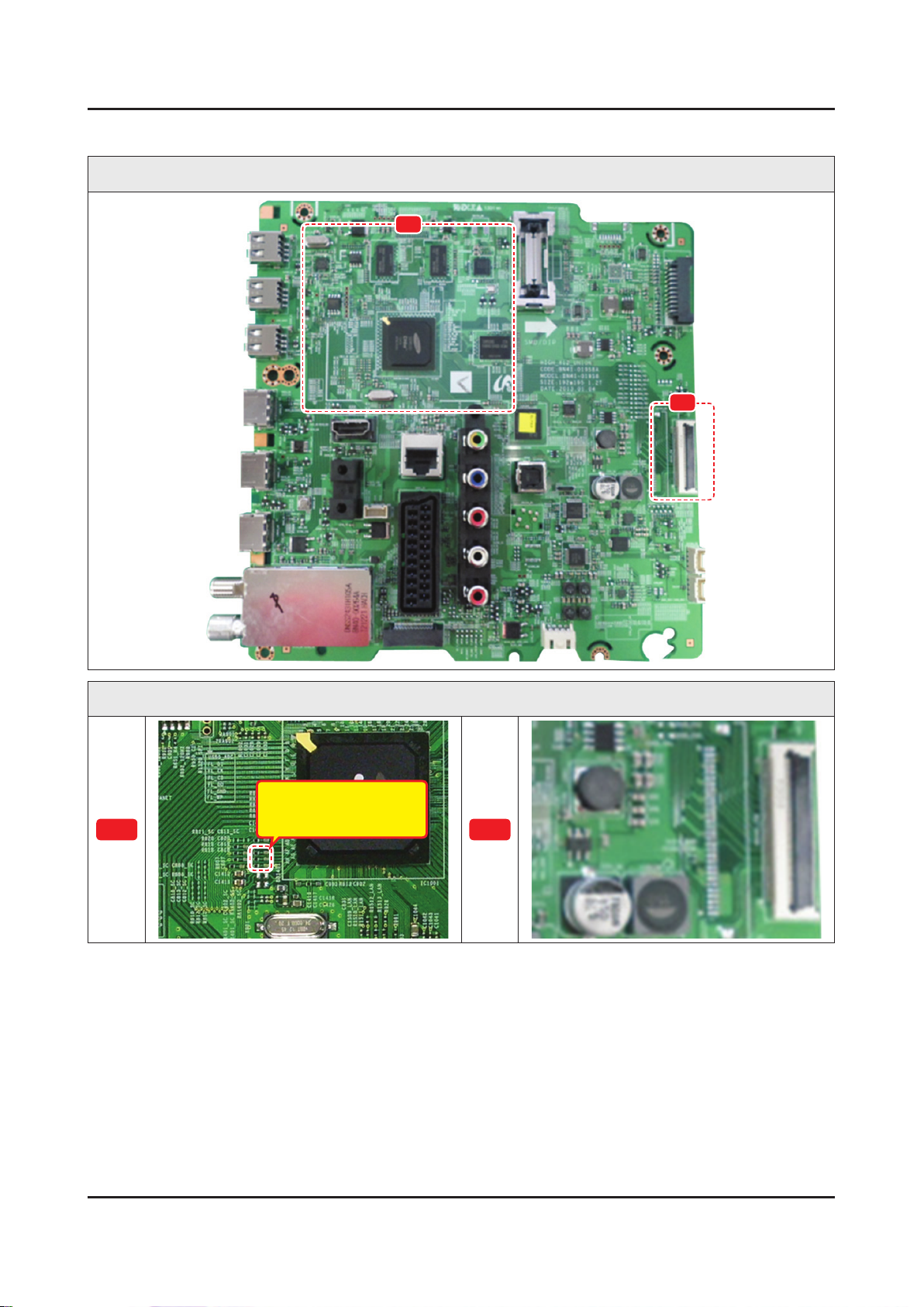
4-2-5. No Video (Video AV)
Note
Refer to the next page to check the location such a CN201 or IC201 SVC Manual mentioned.
Symptom Audio is normal but no picture is displayed on the screen.•
Major
checkpoints
Diagnostics
Caution Make sure to disconnect the power before working on the IP Board.
Check the Video CVBS source.•
This may happen when the LVDS cable connecting the Main Board and the Panel is •
disconnected.
Power indicator LED is off.
Lamp(Backlight) on, no video ?
Yes
Check the video source and check the
connection of video cable?
Yes
Check the LVDS clk signal at output of
2
Replace the T CON / LCD panel?
Main board. (TX)
TX2_CLK : ODD_TXCLK_DN/DP -
TX4_CLK : EVEN_TXCLK_DN/DP -
Yes
Check the LVDS cable?
No
No
No
No
Check a set in the ‘Stand-by mode’.
Input the video source properly.
Check IC1001(X12)
Change the Main Ass’y.
Please, Contact tech support.
Page 17
4-17
4. Troubleshooting
Location of Parts
Main Board_Front
A
B
Detail
A
R816 : COMP2_Y_CVBS
B
Page 18
4-18
4. Troubleshooting
Waveforms
1 CVBS OUT (Grey Bar) 2 LVDS output
Page 19
4-2-6. No Video (COMPONENT)
4-19
4. Troubleshooting
Note
Refer to the next page to check the location such a CN201 or IC201 SVC Manual mentioned.
Symptom Audio is normal but no picture is displayed on the screen.•
Major
checkpoints
Diagnostics
Check the Component source•
This may happen when the LVDS cable connecting the Main Board and the Panel is •
disconnected.
Power indicator LED is off.
Lamp(Backlight) on, no video ?
Yes
Check the component source and check
the connection of component cables ?
Y, Pb, Pr
Yes
Does the component data appear at ?
1
2
COMP2_Y_CVBS : R816 -
Pb : R817 -
Pr : R815 -
Yes
Check the LVDS clk signal at output of
Main Board. (TX)
TX2_CLK : ODD_TXCLK_DN/DP -
TX4_CLK : EVEN_TXCLK_DN/DP -
No
No
No
No
Check a set in the ‘Stand-by mode’.
Input the component source properly.
Check CN502.
Change the Main Ass’y.
Check IC1001(X12).
Change the Main Ass’y.
Yes
Check the LVDS cable?
Replace the T CON / LCD panel?
Caution Make sure to disconnect the power before working on the IP Board.
No
Please, Contact tech support.
Page 20
4-20
4. Troubleshooting
Location of Parts
Main Board_Front
A
B
Detail
R817 : COMP2_PB
R816 : COMP2_Y_CVBS
A
R815 : COMP2_PR
B
Page 21
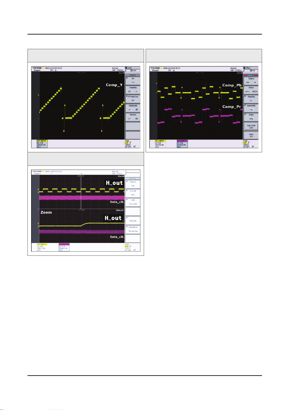
4-21
4. Troubleshooting
Waveforms
1 Compnent_Y (Gray scale) / Pb / Pr (Color bar) 1 Compnent_Y (Gray scale) / Pb / Pr (Color bar)
2 LVDS output
Page 22
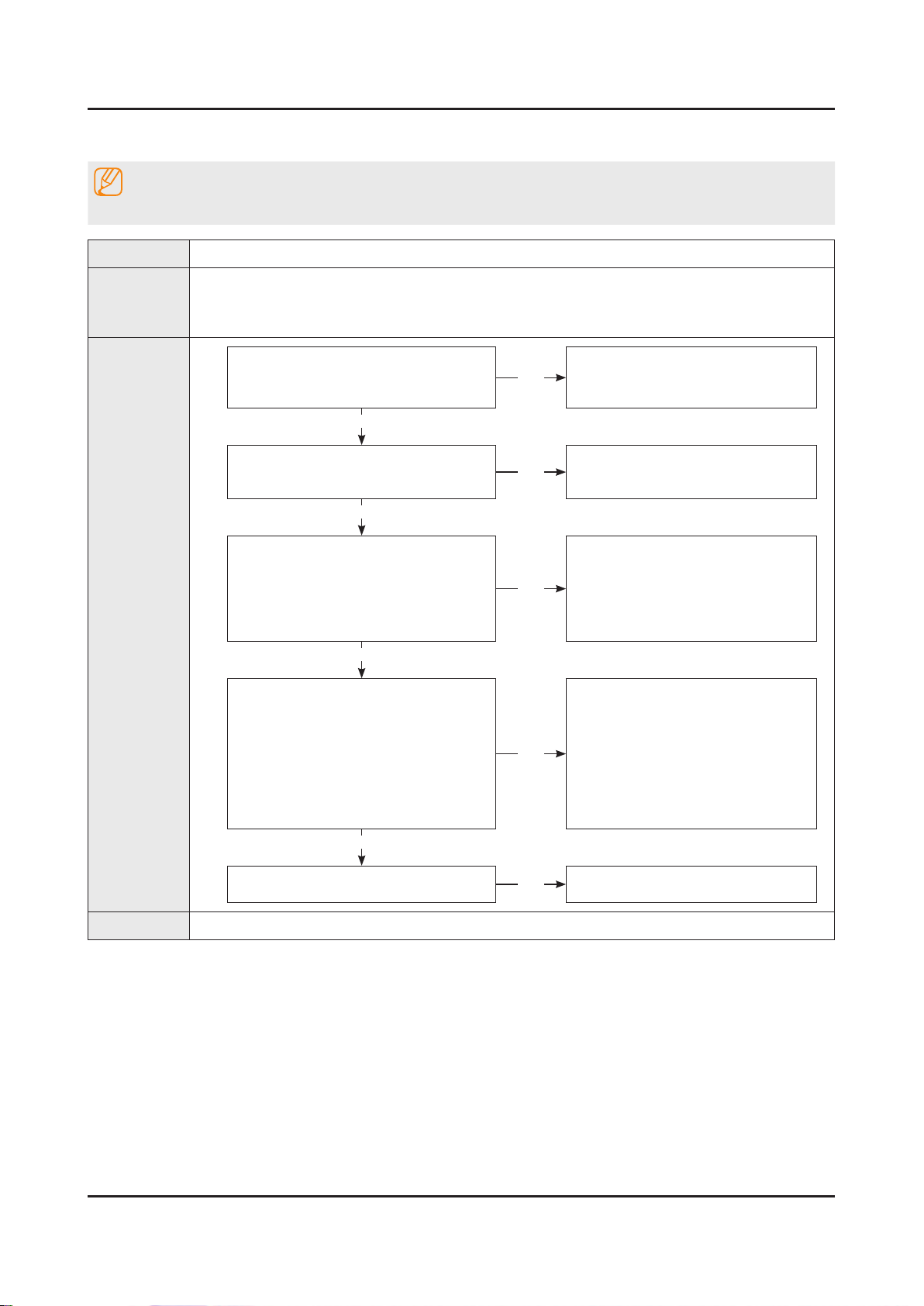
4-22
4. Troubleshooting
4-2-7. No Sound (1.Speaker 2.Monitor_out 3.Optical)
Note
Refer to the next page to check the location such a CN201 or IC201 SVC Manual mentioned.
Symptom Video is normal but there is no sound.•
Major
checkpoints
Diagnostics
When the speaker connectors are disconnected or damaged.•
When the sound processing part of the Main Board is not functioning.•
Speaker defect.•
Check the source and check the
connection of sound cable ?
COMP
Yes
Check the signal at input of Main Board?
AV, COMP L/R : RA503
Yes
Check the DATA between the Audio IC’s ?
Pin #15 of IC301 : B clk -
1
2
Pin #20 of IC301 : LR clk -
Pin #23, #24 of IC301 : I2C_SDA/ -
SCL
Yes
1. Check the Speaker sound data at ?
CN302 -
2. Check the Monitor out sound data at ?
CN303_IBR -
3. Does the SODIF OUT sound data
appear at ?
OP301 -
No
No
No
No
Input the sound source properly.
Check CN502.
Change the Main Ass’y.
Check IC301.
Change the Main Ass’y.
Change the Main Ass’y.
Yes
Replace speaker ?
Caution Make sure to disconnect the power before working on the IP Board.
No
Please, Contact Tech support.
Page 23
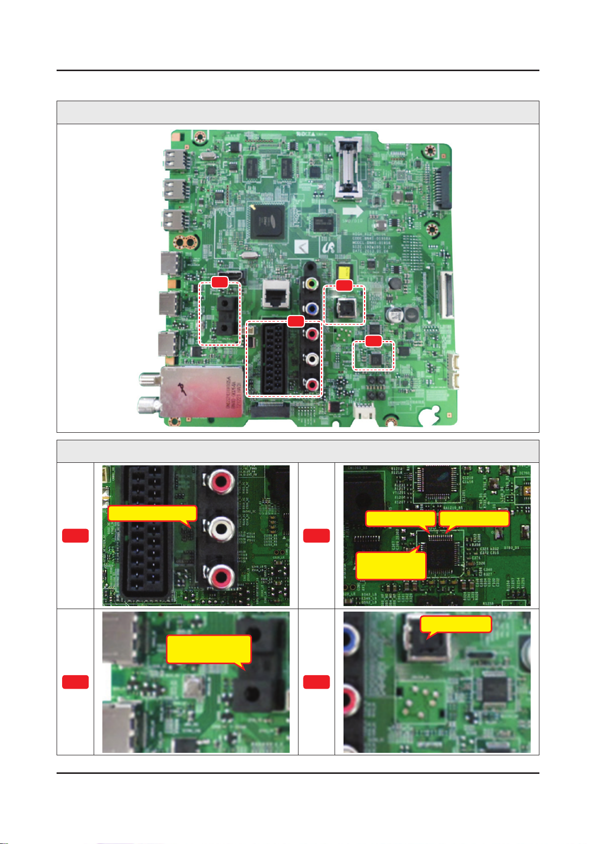
4-23
4. Troubleshooting
Location of Parts
Main Board_Front
C
A
Detail
RA503 : COMP_L/R
A
D
B
Pin #20 : LR clk
B
Pin #23, #24 :
I2C_SDA/SCL
Pin #15 : B clk
OP301 : Optical
CN303_IBR
Monitor out_Sound
C
D
Page 24
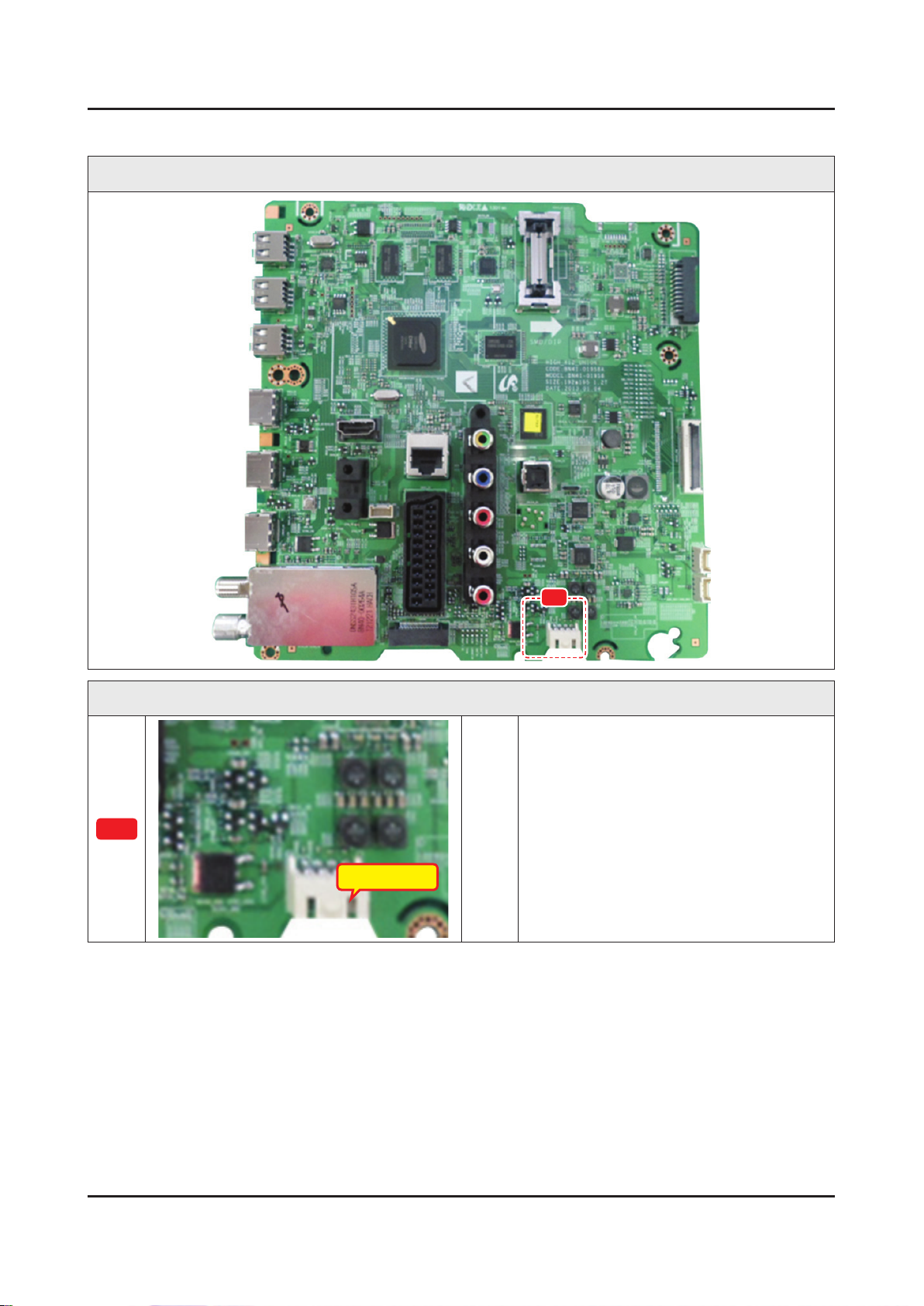
4-24
4. Troubleshooting
Location of Parts
Main Board_Front
E
Detail
E
CN302 : SPK
Page 25
4-25
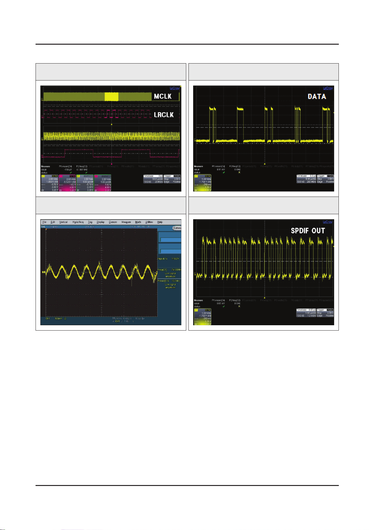
4. Troubleshooting
Waveforms
1 MCLK / LRCLK / PCM_I2C_DATA 1 MCLK / LRCLK / PCM_I2C_DATA
2 Speaker / Monitor OUT , SPDIF OUT 2 Speaker / Monitor OUT , SPDIF OUT
Page 26
4-26
4. Troubleshooting
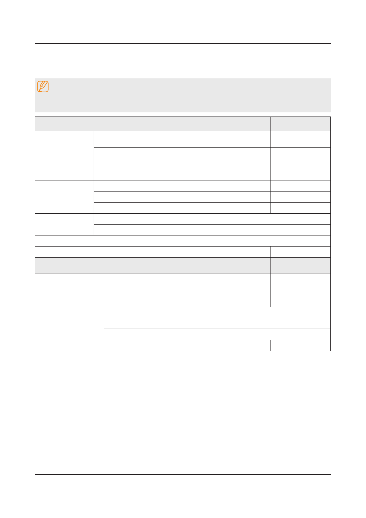
4-3. Factory Mode Adjustments
4-3-1. Detail Factory Option
NOTE
If you replace the main board with new one, please change the factory option as well.
The options you must change are "Type".
Model Name UE40F65**** UE46F65**** UE55F65****
SDC
BN95-00903A
CY-GF400CSLV1H/V
HANSOE HANSOE SEM
BN44-00622B BN44-00623B BN44-00625A
L42X1Q_DHS L46X1Q_DHS L55X1Q_DSM
Depending on Region, Chassis Ass’y is different.
PANEL
SMPS
Vendor
Code
Spec.
Vendor
Code
Spec.
Chassis Ass'y
MAIN ASSY
PBA Ass'y
Depending on Region, PBA Ass’y code is different.
Byte Item
0 Factory Reset
1 Type
2 Local set
3 SW Model
4 BOM Model
- - -
40A1AF6V
EU EU EU
- - -
- - -
TC
SDC
AUO
BN95-00904A
BN07-01276A
CY-GF460CSLV1H/V
GF460CSA-B1
46A1AF6V
46R1AF6V
SI_ADI
SDC
BN95-00905A
CY-GF550CSLV1H/V
55A1AF6V
5 Tuner
6 Ch table
T2C
TCS2
FOX_T2C
SI_TCS2
NONE NONE NONE
Page 27
4-3-2. Entering Factory Mode
4-27
4. Troubleshooting
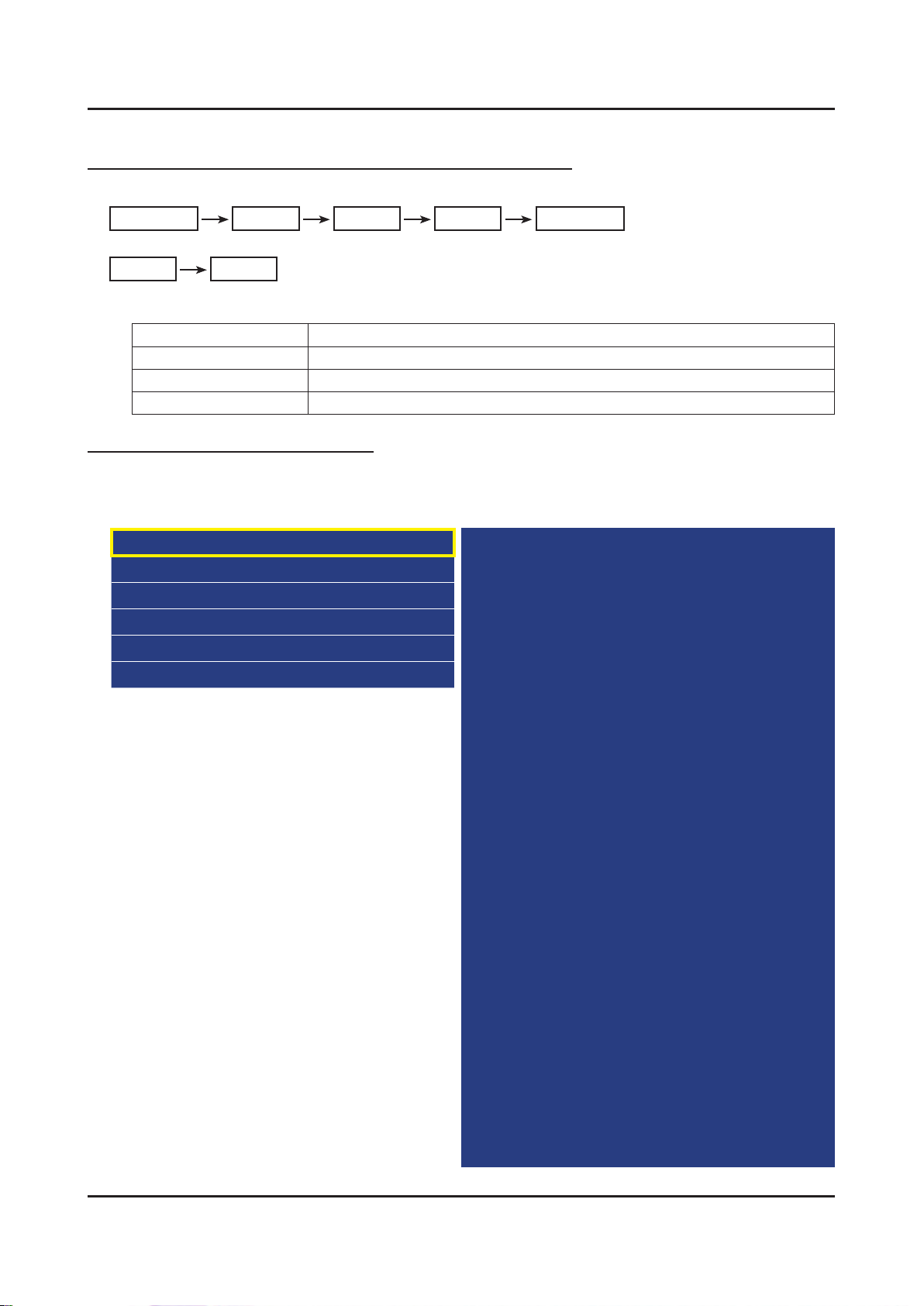
To enter ‘Service Mode’ Press the remote -control keys in this sequence :
If you do not have Factory remote control•
Power OFF INFO MENU MUTE Power On
If you have Factory remote control•
INFO Factory
Buttons operations within Service Mode -
Menu Full Menu Display / Move to Parent Menu
Direction Keys ▲/▼ Item Selection by Moving the Cursor
Direction Keys ◄/► Data Increase / Decrease for the Selected Item
Source Cycles through the active input source that are connected to the unit
HOW to enter the Advanced menu (Picture)
1 Cursor move to ‘Advanced’. → 2 Push the ‘0’ button 4 times. → 3 You can see the ‘Picture’ menu.
If you don’t have Factory remote control, can’t control some menus. (Expert, Advanced menu)•
Option
Control
Debug
SVC
ADC/WB
Advanced
T-MST12DEUC-xxxx
T-MST12DEUS-xxxx
BT Version : xxxx
E-Manual : xxxx
Camera Version : xxxx
Blaster-version : ----
EDID SUCCESS
CALIB : AV/COMP/PC/HDMI/
Option : xxxx,UE,6500,NONE
USB RS232C : OFF
SDAL-X12-MAIN-xxxx-xxxx
RFS : "X12 0102" KER/201x-xx-xx
KERNEL : 8.0837, D / Onboot :xxxx.x
Backend IC[x], Data Ver : xxxx
TCON Version : xxxx
DTP-DTVTD-xxxx
Model : UE46F6500
Wired MAC SUCCESS
Wireless MAC SUCCESS
DRM : Crt O, Nf O, Wv O, Hc O, Dc O, Mx O, MI O
Factory Data Ver : 153
EERC Version : 81
DTP-BP-HAL-3216
DTP-AP-CNC-3197
DTP-AP-MM-3190-01
DTP-AP-WP-3194
DTP-BP-MW-3186
DTP-BP-APP-3186
POP-FLA-13-TEMP
Date of purchase : mm/dd/yyyy
Page 28
4-28
4. Troubleshooting
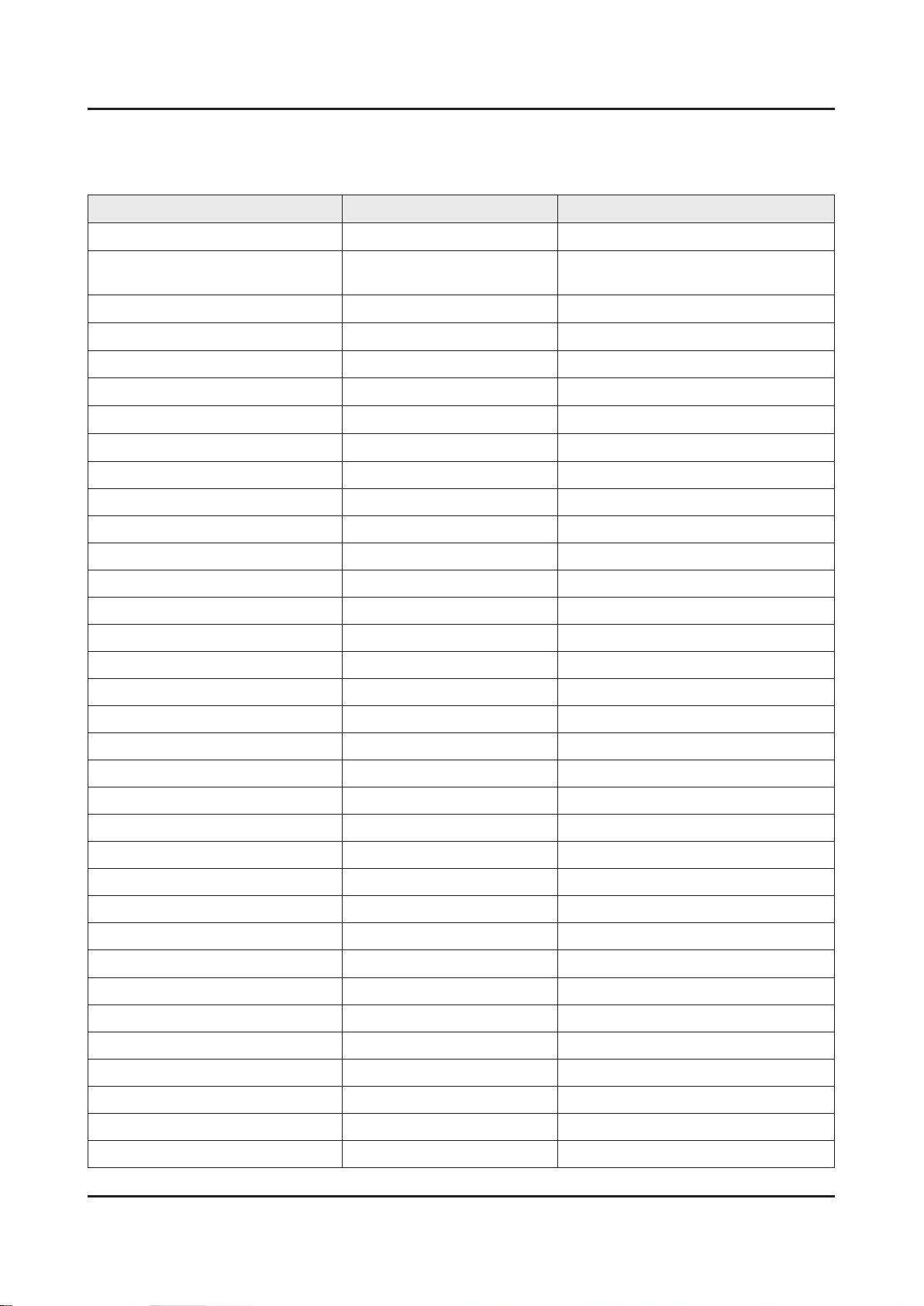
4-3-3. Factory Data
Option
Factory Menu Name Data Range
Factory Reset
Type
-
40A1AF6V / 46A1AF6V /
55A1AF6V
Local Set
SW Model
BOM Model
TUNER
Ch Table
EU
UF6500
6500
SI_ADI / FOX_T2C / SI_TCS2
NONE
MRT Option
Front Color
LVDS FORMAT JEIDA
Language_Arabic US
Region USA
PnP Language ENG_US
WIFI REGION S
OTN Support ON
OTA Support OFF
TTX OFF
China HD OFF
NT Conversion OFF
Num of DTV 1
Num of AV 1
Num of COMP 1
Num of HDMI 4
Num of SCART 0
Num of USB Port 3
Num of HeadPhone 0
Num of RVU 1
Num of Display 2
Num of IPTV 0
Num of RUI 0
Num of PVR RECORD 0
TOOLS Support 40
LNA Support OFF
24Px4 Support OFF
Page 29
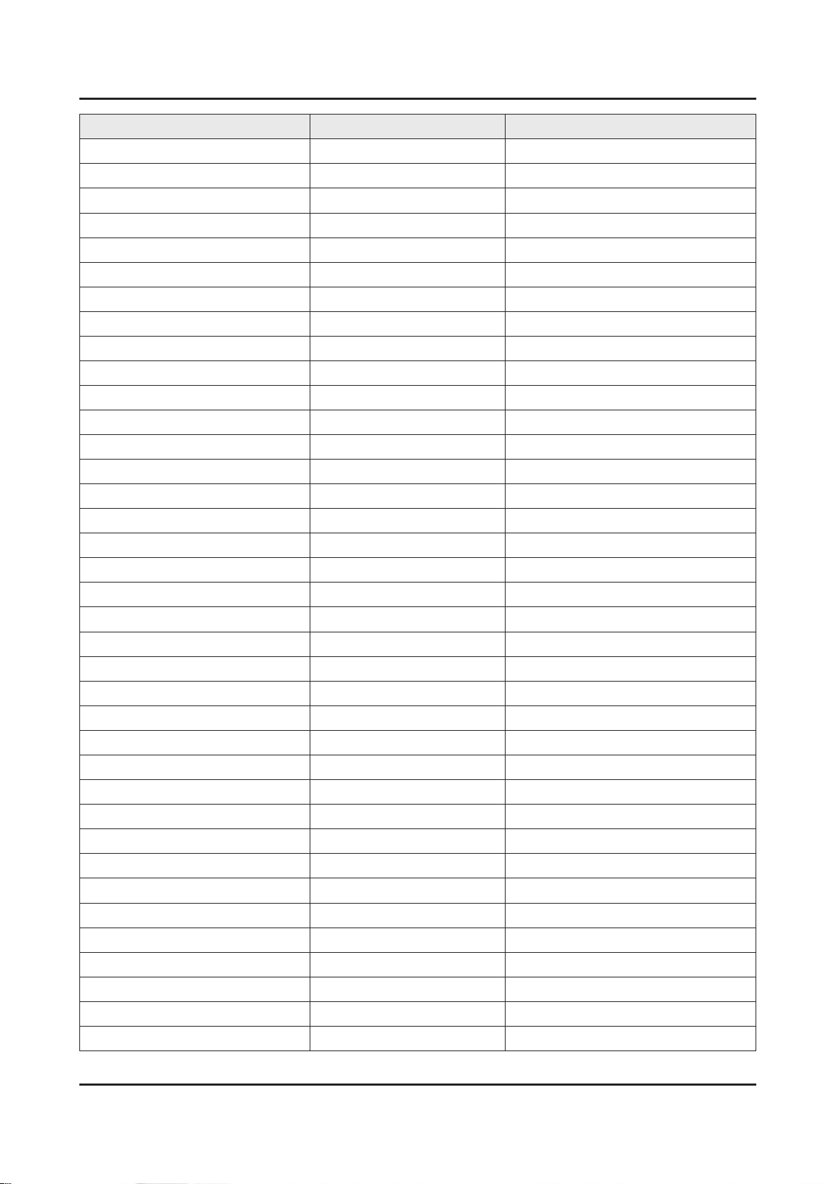
Factory Menu Name Data Range
4-29
4. Troubleshooting
BD Wise Support ON
Data Service Support OFF
PVR Support OFF
CI Support OFF
LEDMotionPlus Support ON
Natural Mode Support ON
Relax Mode Support OFF
HDMI/DVI SEL 4
Select LCD/PDP LCD
Wall Mount OFF
HV Flip HV Flip / H Filp / OFF
Light Effect OFF
e-Pop Default 1
CAMERA Support OFF
NETWORK Support 3
EcoSensor Support ON
3D Support ON
BT Support ON
BT ADDRESS
Engineer Option
Auto Power MEMORY
Type Of PANEL KEY None
5 Way Function Key R BACK
Contents Bar OFF
Cable Modulation QAM
Standby led on/off OFF
Recognition Support
IF AGC 0
D AGC 0
PH BW 0
FQ BW 0
PH RATE 0
PD EN 0
PEQ Inx 0
WF Scale
WF Type 0
Nu of Network Stream 1
Page 30
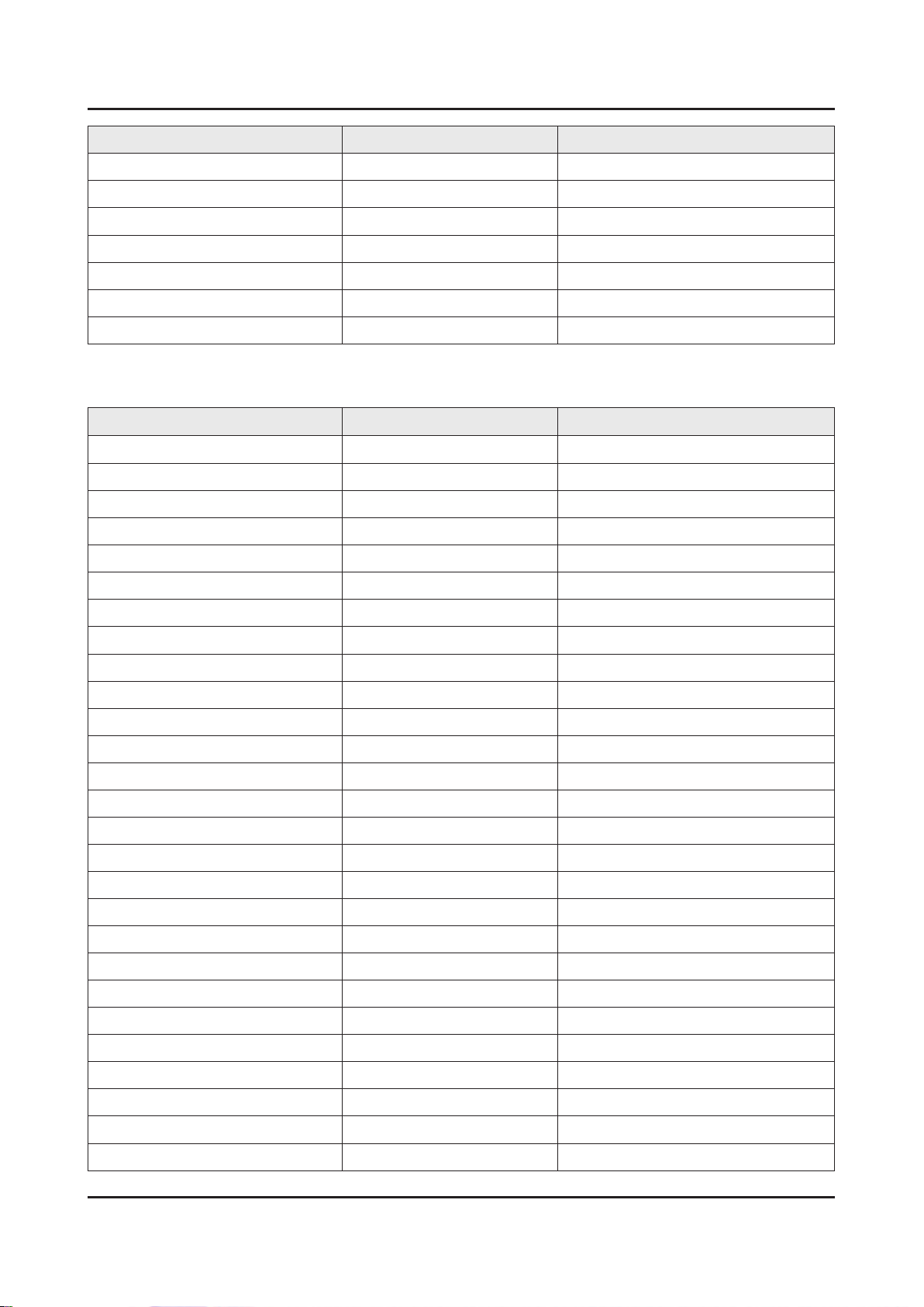
4-30
4. Troubleshooting
Factory Menu Name Data Range
DP V Size 0
Backend Device FOX-FT1
BT_AUDIO_ON_OFF OFF
Cong_AV_PATH
ECO Standby OFF
Fast Logo Delay 0
Num of PANEL KEY 6
Control
Factory Menu Name Data Range
EDID
EDID ON/OFF OFF
EDID WRITE ALL …
EDID WRITE HDMI …
EDID Ver …
EDID Port
Sub Option
RS-232 Jack UART Debug/UART
Watchdog OFF
Checksum 0x0000
Fast Boot in Production OFF
USB Serial OFF
Eeprom Reset
ECO IC TYPE NONE
Info Link Server Type development
Info Link Country None
TTX Group -
Visual Test -
MediaPlayDB -
OPTION_SWU
OTN Server Type operating
OTN Test Server OFF
SWU Reset
SWU Duration OFF
SWU Fail Test OFF
OPTION_NUM
Num of ATV 1
Page 31
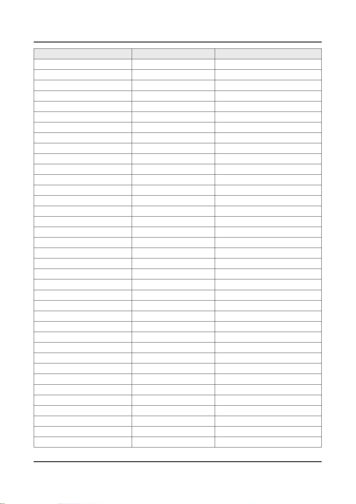
Factory Menu Name Data Range
4-31
4. Troubleshooting
Num of SVIDEO 0
Num of PC 0
Num of DVI 0
Num of OPTICAL Link 1
Num of MEDIA 1
Num of Tuner 1
Num of ISP 1
RF Remocon Support OFF
CDD mode -
DPMS Support OFF
Num of IPTV CIP 0
Num of CI 0
Num of DECODER 0
T-CON Device
BOARD CONTROL OFF
HP LINE LineOut
RM
Server Type Operating
RTS Mode OFF
PSA
FKP Download1 0
FKP Download2 0
LMK threshold 3
Low threshold 10
High threshold 15
CSB ON
CLB ON
PDP Option
Pixel Shift Test OFF
Logic SW 0
Panel Temperature 0
LOGIC Waveform Day 0
Logic CheckSum 0
MRT 0
SAPC Timer
APC Speed
Hotel Option
Page 32
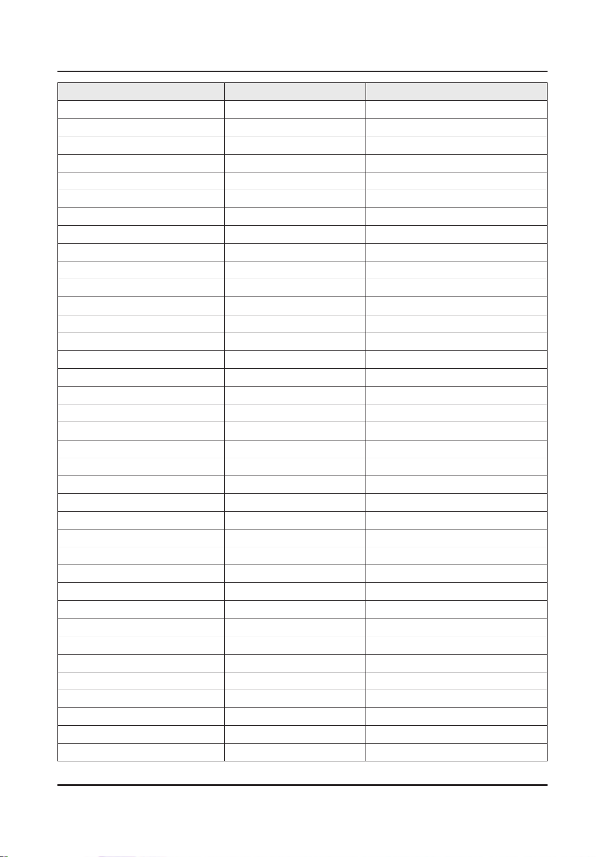
4-32
4. Troubleshooting
Factory Menu Name Data Range
Hospitality Mode OFF
Power On …
Menu OSD …
Operation …
Music Mode …
External Source …
Eco Solution …
Cloning …
Shop Option
Shop Mode OFF
Exhibition Mode OFF
3D Cube OFF
Asia Option
Unbalance OFF
AF Level adjust 3
TX Power Level 0
Mono Last Memory OFF
H Shaking OFF
SOUND
Carrier_Mute OFF
High Devi OFF
Speaker Delay Normal 0x6Eh
SPDIF PCM Gain -9dB
FM M Prescale 0x30h
FM Prescale 0x00h
AM Prescale 0x32h
NICAM Prescale 0x48h
BTSC Mono Prescale 0x19h
BTSC stereo Prescale 0x2Fh
BTSC SAP Prescale 0x2Bh
A2Ident High THID 31
A2Ident Low THID 0
Pilot Level High Thld 0x28h
Pilot Level Low Thld 0x10h
Carrier2 Amp High THID 4
Carrier2 Amp Low THID 3
Carrier2 SNR High THR 16
Page 33
Factory Menu Name Data Range
4-33
4. Troubleshooting
Carrier2 SNR Low THR 80
Sig Error On 35
Sig Error Off 41
Amp Model TAS5745
Amp Volume 0xcbh
Amp Scale 0x35h
Amp Check Sum 0x000821B2
Woofer Type 0
Woofer Scale 0
Woofer Check Sum 0x8ah
Woofer Local EQ Checksum 0
Speaker EQ ON
PEQ Test Ready
Local Speaker EQ 0
Local EQ Checksum 0
Speaker cut-off Ferq 4
Audio-IP Test
SRS Tuning Parm 0
TruBass-CheckSum 0
Mic Scale 0
Subwoofer Support 0
India Sound OFF
AudioDock BT delay 50
Wall Filter Type 0
Wiselink Delay Menu 90
Debug
Factory Menu Name Data Range
Spread Spectrum
LVDS Spread ON
DDR Spread 1.0% Spectrum
Period 30K
Amplitude 1
HD SSC ON/Off ON
HD SSC Value 1
LVDS SSC ON/Off ON
LVDS SSC Value 0
Page 34
4-34
4. Troubleshooting
Factory Menu Name Data Range
DDR SSC ON/Off ON
DDR SSC Value 1
FRC LVDS SSC ON/OFF ON
FRC LVDS SSC MRR 10
FRC LVDS SSC MFR 1
FRC LVDS SSC Period 1
FRC LVDS SSC Modulation 1
FRC DDR SSC ON/OFF ON
FRC DDR SSC MRR 15
FRC DDR SSC MFR 1
FRC DDR SSC Period 1
FRC DDR SSC Modulation 1
DDR Margin
A CTRL_OFFSET_0_3 0x0
A CTRL_OFFSET_D 0x0
B CTRL_OFFSET_0_3 0x0
B CTRL_OFFSET_D 0x0
ND ADJ Support
MICOM POWER OFF
RF Mute Time
CI+1.3
OFF
OFF
6ms
OFF
FRC
FRC FDISPLAY ON/OFF 0
3D FDISPLAY ON/OFF OFF
PC Mode ON/OFF OFF
Tuner Margin
MPEG Margin
H.264 Margin
10
1000
8
CAM Wait Time
TS Clock deldy
TCON_TEMP READ
0
0
TEMP LAST
DCC VERSION
DCC CHK SEL
DCC CHECK LOCAL
DCC CHECK TOTAL
MulitACC Checksum
60
0x0
0
0x0
0x0
0
Page 35
Factory Menu Name Data Range
4-35
4. Troubleshooting
IIC Bus stop
Tuner Status
DVB
SNR
BER
Signal Strength
Bandwidth
Frequency
LNA Status
FFT
Modulation
Code Rate
GI
Hier Modulation
Frequency offset
Timing offset
AGC
OFF
UCB
PLL Type
DEMOD Type
TPS Lock
RS Lock
SSI
SQI
Firmware Version
ISDB-T
FFT Size_1
Guard Interval_1
Freq. Offset_1
SNR_1
IF AGC_1
TMCC Lock_1
TS Packer_1
Master Lock_1
A_Modulation_1
A_Code Rate_1
A_Timer InterLeave_1
Page 36
4-36
4. Troubleshooting
Factory Menu Name Data Range
A_Segments Num_1
A_BER_1
B_Modulation_1
B_Code Rate_1
B_Timer InterLeave_1
B_Segments Num_1
B_BER_1
C_Modulation_1
C_Code Rate_1
C_Timer InterLeave_1
C_Segments Num_1
C_BER_1
SVC
Factory Menu Name Data Range
Test Pattern
Pattern Sel OFF
Logic Pattern Sel …
Logic Level Sel …
FRC Pre Test Pattern 0
FRC Post Test Pattern 0
FRC3D Fdisplay OFF
FRC3D PC Mode OFF
SOC TCON Test Pattern 0
SOC TCON Pattern Level 255
SOC TCON FRC Pattern 0
HDMI WB Pattern OFF
HDMI Pattern Sel 0
Parma Pre Test Pattern 0
Parma Post Test Pattern 0
Panel Display Time
0Hr
SVC Info
Delete S/N
0
0
Upgrade
T-CON Usb Download Failute
T-CON CheckSum Error
Logic Usb D/L …
Page 37

Factory Menu Name Data Range
4-37
4. Troubleshooting
SUBMICOM UPGRADE Failute
BT UPGRADE
BT FREEPAIRING ON
Function Upgrade Failute
FRC3D FW Upgrade
Camera Upgrade
Mic Upgrade
CPLD USB Download
JP MICOM UPGRADE Failute
DP MICOM UPGRADE Failute
Jump Upgrade Failute
Smart Hub Reset
0
ER Count
WD Count 0
AR Count 0
WIFI ER Count 0
BT ER Count 0
HDMI Err Cnt 0
Camera ER Count 0
LOG(View Log)
Select Log Type NVRAM
Log View 0
Delete Log
Debug Log Down
Emergency Log Copy
Self Diagnosis
Loop Back
LAN Test
AV Audio Test
DVIN Audio Test
CVBS Test
COMP Test
USB HUB Test
HDMI Test
SCART Audio Test
SCART CVBS Test
SCART RGB Test
Page 38
4-38
4. Troubleshooting
Factory Menu Name Data Range
CPU
DDR
FLASH
EEPROM
Sound AMP
HDMI Switch IC
USB HUB IC
WIFI
LVDS
T-CON/FRC
PCB Test
MOIP
App Self Test
Device self Test
Voltage
EcoSensor
BT
EXT Sound Inspection
Woofer Sound Inspection NONE
ATV CH Inspection
DTV CH Inspection
Satellite CH Inspection
IPERF
Stopped
OPTION HDMI
Expert
DVB CI
CAL Data Backup
CAL Data Restore
…
…
ADC/WB
Factory Menu Name Data Range
ADC
AV Calibration Success
Comp Calibraion Success
PC Calibration Success
HDMI Calibration Success
ADC Result
Page 39
Factory Menu Name Data Range
4-39
4. Troubleshooting
1st_Y_GH 258
1st_Y_GL 128
1st_Cb_BH …
1st_Cb_BL …
1st_Cr_RH …
1st_Cr_RL …
2nd_R_L 132
2nd_G_L 132
2nd_B_L 132
2nd_R_H 70
2nd_G_H 70
2nd_B_H 70
White Balance
R-Offset 128
G-Offset 128
B-Offset 128
R-Gain 128
G-Gain 128
B-Gain 128
WB_W2_R_Offset 128
WB_W2_B_Offset 128
WB_W2_R_Gain 164
WB_W2_B_Gain 63
WB_N_R_Offset 128
WB_N_B_Offset 128
WB_N_R_Gain 151
WB_N_B_Gain 108
MGA
MGA On/Off OFF
R1_Gain …
B1_Gain …
G1_Gain …
R2_Gain …
B2_Gain …
G2_Gain …
R3_Gain …
B3_Gain …
Page 40
4-40
4. Troubleshooting
Factory Menu Name Data Range
G3_Gain …
R4_Gain …
B4_Gain …
G4_Gain …
R5_Gain …
B5_Gain …
G5_Gain …
R6_Gain …
B6_Gain …
G6_Gain …
R7_Gain …
B7_Gain …
G7_Gain …
R8_Gain …
B8_Gain …
G8_Gain …
R9_Gain …
B9_Gain …
G9_Gain …
R10_Gain …
B10_Gain …
G10_Gain …
Page 41
4-4. White Balance
4-41
4. Troubleshooting
4-4-1. Calibration
Into the Factory Mode.1.
Select 2. ADC/WB menu.
Select 3. ADC menu.
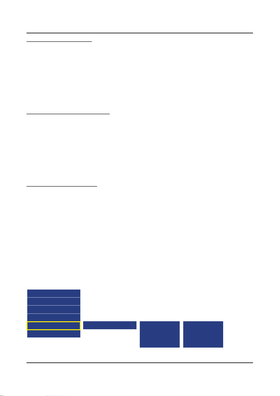
Option
Control
Debug
SVC
ADC/WB
Advanced
AV Calibration
Comp Calibration
HDMI Calibration
4-4-2. Service Adjustment
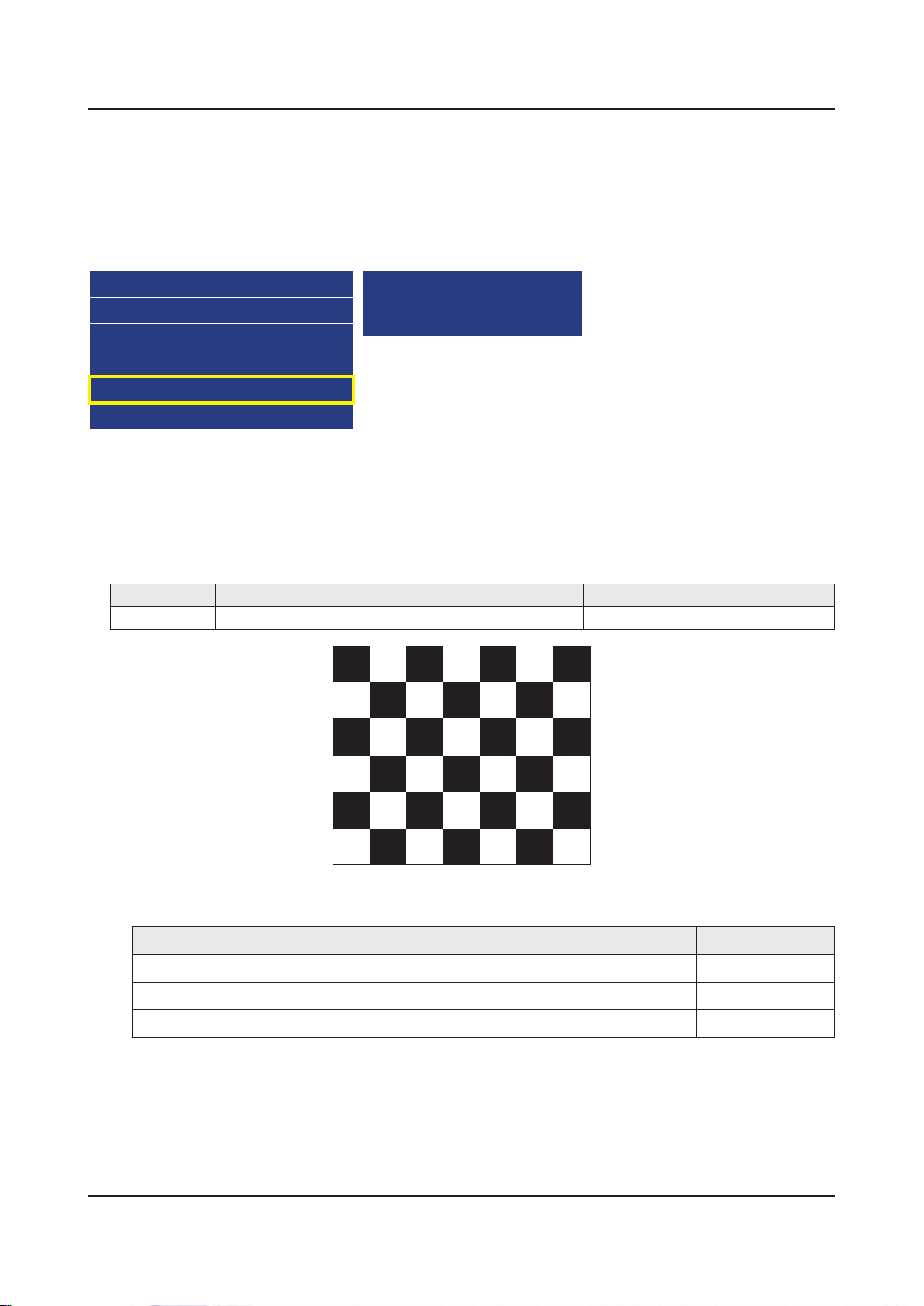
You must perform Calibration in the Lattice Pattern before adjusting the White Balance.
Color Calibration
Adjust Specication•
Source Setting Mode Pattern Use Equipment
HDMI 1280 x 720@60 Hz Pattern #24 (Chess Pattern) CA210 & Master MSPG925 Generator
(Chess Pattern)
Use other equipment only after comparing the result with that of the Master equipment. -
Input mode Calibration Pattern
CVBS IN (Model_#1) Perform in NTSC B&W Pattern #24 Lattice
Component IN (Model_#6) Perform in 720p B&W Pattern #24 Lattice
HDMI IN Perform in 720p B&W Pattern #24 Lattice
Page 42
4-42
4. Troubleshooting
Method of Color Calibration (AV)
Apply the NTSC Lattice (N0. 3) pattern signal to the AV IN 1 port.1.
Press the Source key to switch to “AV1” mode.2.
Enter Service mode.3.
Select the “ADC” menu.4.
Select the “AV Calibration” menu.5.
In “AV Calibration Off” status, press the “► ” key to perform Calibration.6.
When Calibration is complete, it returns to the high-level menu.7.
You can see the change of the “AV Calibration” status from Failure to Success. 8.
Method of Color Calibration (Component)
Apply the 720p Lattice (N0. 6) pattern signal to the Component IN 1 port.1.
Press the Source key to switch to “Component1” mode.2.
Enter Service mode.3.
Select the “ADC” menu.4.
Select the “Comp Calibration” menu.5.
In “Comp Calibration Off” status, press the “ ►” key to perform Calibration.6.
When Calibration is complete, it returns to the high-level menu.7.
You can see the change of the “Comp Calibration” status from Failure to Success.8.
Method of Color Calibration (HDMI)
Apply the 720p Lattice (N0. 6) pattern signal to the HDMI1/DVI IN port.1.
Press the Source key to switch to “HDMI1” mode.2.
Enter Service mode.3.
Select the “ADC” menu.4.
Select the “HDMI Calibration” menu.5.
In “HDMI Calibration Off” status, press the “►” key to perform Calibration.6.
When Calibration is complete, it returns to the high-level menu.7.
You can see the change of the “HDMI Calibration” status from Failure to Success.8.
4-4-3. Adjustment
Into the Factory Mode.9.
Select 10. ADC/WB menu.
Select 11. White Balance menu.
Option
Control
Debug
SVC
ADC/WB
Advanced
White Balance
(Low Light)
Sub Brightness
R offset
G offset
B offset
(Hight Light)
Sub Contrast
R gain
G gain
B gain
Page 43
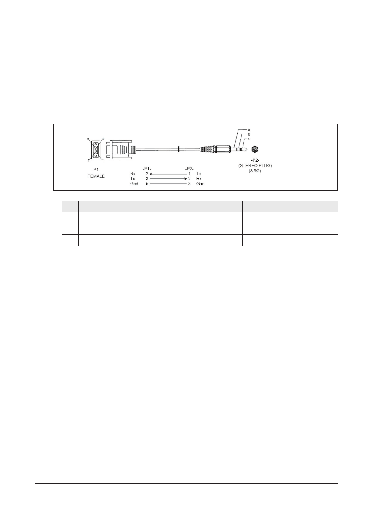
4-5. RS-232C
4-43
4. Troubleshooting
RS232C Control•
Port : COM#(Serial) -
Bit rate : 115200 -
Data Bit : 8 bit -
Parity : None -
Stop Bits : 1 -
Flow Control : None -
Description of RS232C•
Pin# Name Full Name Pin# Name Full Name Pin# Name Full Name
CD Carrier Detect
1
RxD Received Data
2
TxD Transmitted Data
3
DTR Data Terminal Ready
4
GND Signal Ground
5
DSR Data Set Ready
6
RTS Request To Send
7
CTS Clear To Send
8
RI Ring Indicator
9
Page 44
4-44
4. Troubleshooting
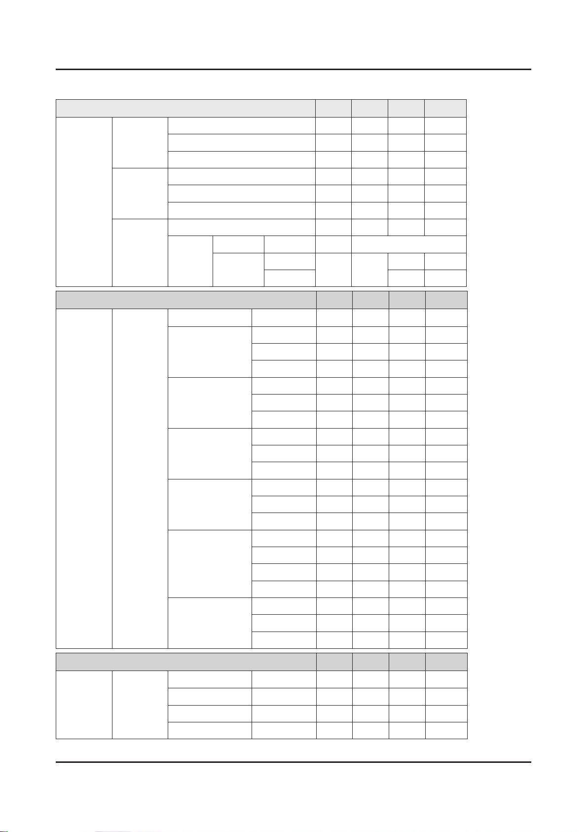
4-6. AV Control Tabe
Control Item Cmd1 Cmd2 Cmd3 Value
General
Input
Power Power 0x00 0x00 0x00 0x00
Off 0x01
On 0x02
Volume Direct 0x01 0x00 0x00 (0~100)
Up 0x01 0x00
Down 0x02 0x00
Mute 0x02 0x00 0x00 0x00
Ch. Direct 0x04 -
Continuous Up
0x03 0x00
Down 0x02 0x00
0x01 0x00
Control Item Cmd1 Cmd2 Cmd3 Value
Source List TV
AV AV1 0x01 0x00
S-Video S-Video1 0x02 0x00
TV 0x0a 0x00 0x00 0x00
AV2 0x01
AV3 0x02
S-Video2 0x01
PICTURE
Component Component1 0x03 0x00
PC PC1 0x04 0x00
HDMI HDMI1 0x05 0x00
DVI DVI1 0x06 0x00
Control Item Cmd1 Cmd2 Cmd3 Value
Mode Dynamic(Entertain)
Standard 0x01
S-Video3 0x02
Component2 0x01
Component3 0x02
PC2 0x01
PC3 0x02
HDMI2 0x01
HDMI3 0x02
HDMI4 0x03
DVI2 0x01
DVI3 0x02
0x0b 0x00 0x00 0x00
Movie 0x02
Natural 0x03
Page 45
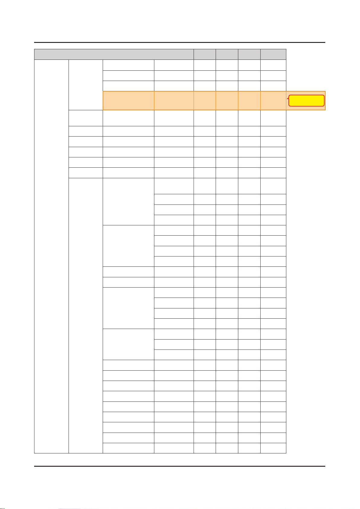
Control Item Cmd1 Cmd2 Cmd3 Value
4-45
4. Troubleshooting
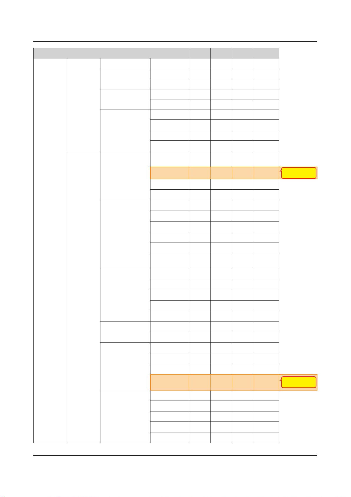
PICTURE
Mode CAL-NIGHT
CAL-DAY 0x05
BD Wise 0x06
Relax
BackLight
(CellLight)
Contrast 0~100 0x02 0x00 (0~100)
Brightness 0~100 0x03 0x00 (0~100)
Sharpness 0~100 0x04 0x00 (0~100)
Color 0~10 0x05 0x00 (0~100)
Tint G/R 0x06 0x00 (0~100)
Advanced
Settings
Black Tone
Dynamic Contrast Off 0x01 0x00
0~20 0x01 0x00 (0~20)
Off 0x07 0x00 0x00
Dark 0x01
Darker 0x02
Darkest 0x03
0x04
0x07
New function of 12"
(only PDP TV)
Low 0x01
Medium 0x02
HIgh 0x03
Shadow Detail -2 ~ 2 0x02 (-2~2)
Gamma -3 ~ 3 0x03 (-3~3)
RGB Only Mode Off 0x05 0x00
Red 0x01
Green 0x02
Blue 0x03
Color Space Auto 0x06 0x00
Native 0x01
Custom 0x02
White Balance R-Offset(LCD) 0x07 (0~50)
White Balance G-Offset(LCD) 0x08 (0~50)
White Balance B-Offset(LCD) 0x09 (0~50)
White Balance R-Gain(LCD) 0x0a (0~50)
White Balance G-Gain(LCD) 0x0b (0~50)
White Balance B-Gain(LCD) 0x0c (0~50)
White Balance Reset(LCD) 0x0d 0x00
Flesh Tone -15 ~ 15 0x0e (-15~15)
Edge Enhancement Off 0x0f 0x00
Page 46
4-46
4. Troubleshooting
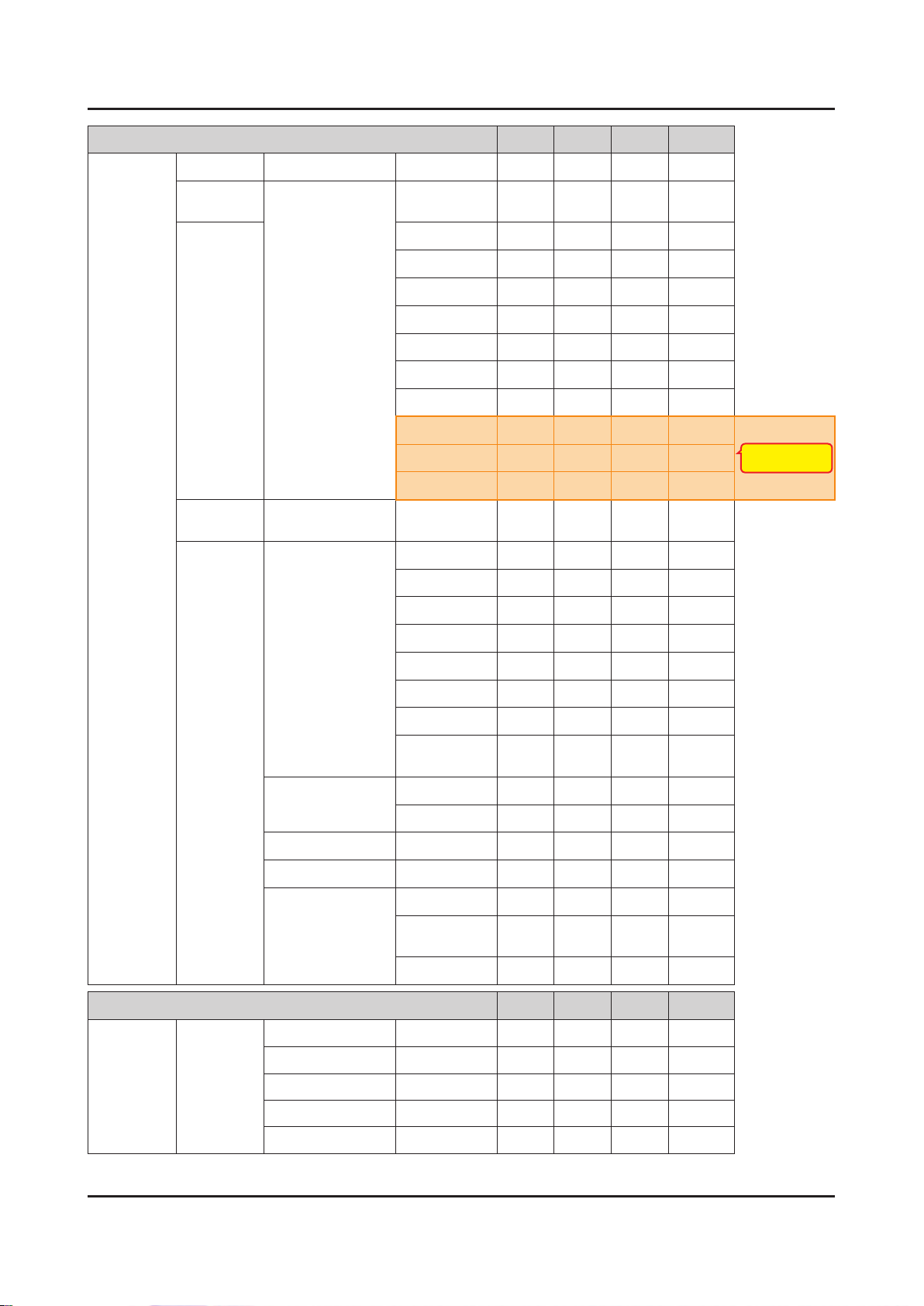
Control Item Cmd1 Cmd2 Cmd3 Value
PICTURE
Picture
Option
On 0x01
xvYCC Off 0x10 0x00
On 0x01
Motion Lighting Off 0x11 0x00
On 0x01
LED Motion Plus Off 0x0a 0x07 0x00
Color Tone
Digital Noise Filter
On(Normal)
Cinema
Ticker
Cool 0x0a 0x00
Standard
Warm1
Warm2
Off 0x02
Low
Medium
0x01
0x02
0x03
0x00
0x01
0x02
0x03
0x00
0x01
0x02
Change Normal →
Standard mode
MPEG Noise Filter
HDMI Black Level
Film Mode
Auto Motion Plus
High
Auto
Auto
Visualization
Off 0x03
Low
Medium
High
Auto
Normal 0x04
Low
Off 0x05
Auto1
Auto2
Cinema
Smooth
Off 0x06
Clear
0x03
0x04
0x05
0x00
0x01
0x02
0x03
0x04
0x00
0x01
0x00
0x01
0x02
0x03
0x00
0x01
New function of 12"
(only PDP TV)
Standard
Smooth
Custom
0x02
0x03
0x04
Page 47
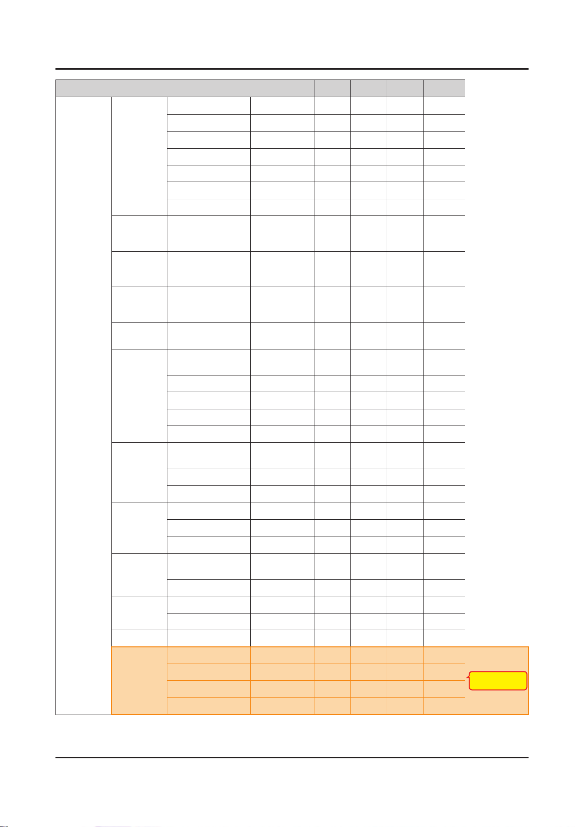
Control Item Cmd1 Cmd2 Cmd3 Value
4-47
4. Troubleshooting
PICTURE
Screen
Adjustment
Reset
Picture
3D 3D Mode
Picture Size
Reset Picture
Demo
16:9 0x0b 0x0a 0x01
Zoom1
Zoom2
Wide Fit
4:3
Screen Fit
Smart View I
Smart View II
Auto Wide
Wide Zoom
Zoom
0x0b 0x0b 0x00
Off 0x0b 0x0c 0x00
2D
⇢
3D
Side By Side
0x05
0x00
0x01
0x02
0x03
0x04
0x05
0x06
0x07
0x08
0x09
0x0a
0x00
0x00
0x01
0x02
New function of 12"
(only DVB TV)
Sound
3D ⇢ 2D
3D View Point
Depth
3D Auto View
Control Item Cmd1 Cmd2 Cmd3 Value
Sound Mode Standard
Music 0x01
Movie 0x02
Top Bottom
Line By Line
Vertical Line
Checker BD
Frame
Sequence
Off 0x01
On
0x02
0x03
Off 0x05
Message
Notice
On
0x0c 0x00 0x00 0x00
0x03
0x04
0x05
0x06
0x07
0x00
0x01
(-5~5)
(1~10)
0x00
0x01
0x02
Clear Voice 0x03
Amplify 0x04
Page 48
4-48
4. Troubleshooting
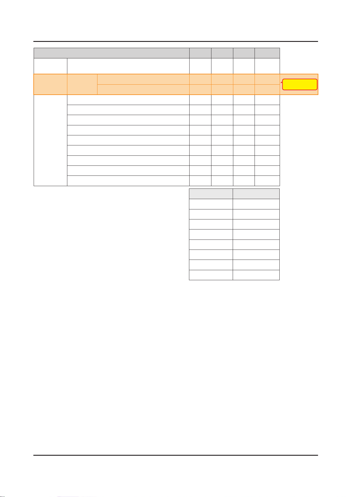
Control Item Cmd1 Cmd2 Cmd3 Value
Sound
Equalizer Balance
100hz 0x01 (0~20)
300hz 0x02 (0~20)
1khz 0x03 (0~20)
3khz 0x04 (0~20)
10khz 0x05 (0~20)
Reset 0x06 0x00
SRS
TruSurround
HD (echo)
Virtual
Surrond
(echo)
SRS
TruDialog
(echo)
Dialog Clarify
(X9)
Preferred
Language
Off
On
Off
On
English
Spanish 0x01
0x01 0x00 (0~20)
0x02 0x00 0x00
0x01
0x03 0x00 0x00
0x01
0x04 0x00 0x00
French 0x02
Korean 0x03
Japanese 0x04
Multi-Track
Sound
Auto Volume Off 0x06 0x00 0x00
Speaker
Select
Sound Select Main 0x08 0x00 0x00
Sound Reset Sound Reset 0x09 0x00 0x00
3D Audio Off 0x0a 0x00 0x00
Mono
Stereo 0x01
SAP 0x02
ON 0x01
Night 0x02
TV Speaker
External Speaker 0x01
Sub 0x01
Low 0x01
Medium
0x05 0x00 0x00
0x07 0x00 0x00
0x02
New function of 12"
High 0x03
Page 49
Control Item Cmd1 Cmd2 Cmd3 Value
4-49
4. Troubleshooting
KEY
OSD
Get
Status
Key Generation
Show/Hide
Control
Power (On/Off) 0xf0 0x00 0x00 0x00
Volume(0~100) 0xf0 0x01 0x00 0x00
Mute (On/Off) 0xf0 0x02 0x00 0x00
Channel Number 0xf0 0x03 0x00 0x00
Source (TV/AV/…/HDMI/…) 0xf0 0x04 0x00 0x00
Picture Size 0xf0 0x05 0x00 0x00
3D (On/Off) 0xf0 0x06 0x00 0x00
Picture Mode 0xf0 0x07 0x00 0x00
Sound Mode 0xf0 0x08 0x00 0x00
Show
Hide 0x01
0x0d 0x00 0x00
0x0e 0x00 0x00 0x00
refer to
table
Key value Value
Up 96 (0x60)
Down 97 (0x61)
Left 101 (0x65)
New function of 12"
Right 98 (0x62)
Menu 26 (0x1A)
Internet 147 (0x93)
Enter(OK) 104 (0x68)
EXIT 45 (0x2D)
Page 50
4-50
4. Troubleshooting
4-7. Software Upgrade
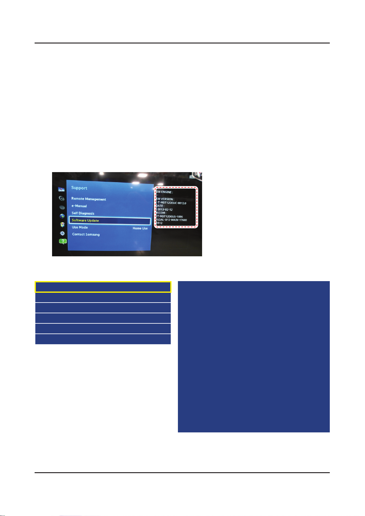
Software Upgrade can be performed by downloading the. latest rmware from samsung.com to a USB memory device.
Current Version - The software already installed in the TV.•
Software is represented as ‘Year/Month/Day_Version’.
4-7-1. How to Check the Software Version
Use the Main Menu
Click the "MENU" key in remote controller.1.
Select "Support" menu.2.
Locate the menu cursor "Software Upgrade" menu.3.
Click the "INFO" key.4.
Check the Main SW and Micom version. -
Use the Factory Mode
Option
Control
Debug
SVC
ADC/WB
Advanced
T-MST12DEUC-xxxx
T-MST12DEUS-xxxx
BT Version : xxxx
E-Manual : xxxx
Camera Version : xxxx
Blaster-version : ----
EDID SUCCESS
CALIB : AV/COMP/PC/HDMI/
Option : xxxx,UE,6400,NONE
USB RS232C : OFF
SDAL-X12-MAIN-xxxx-xxxx
RFS : "X12 0071" KER/201x-xx-xx
KERNEL : 8.0837, D / Onboot :xxxx.x
Backend IC[x], Data Ver : xxxx
TCON Version : xxxx
DTP-DTVTD-xxxx
Page 51
4-7-2. How to Upgade Software
4-51
4. Troubleshooting
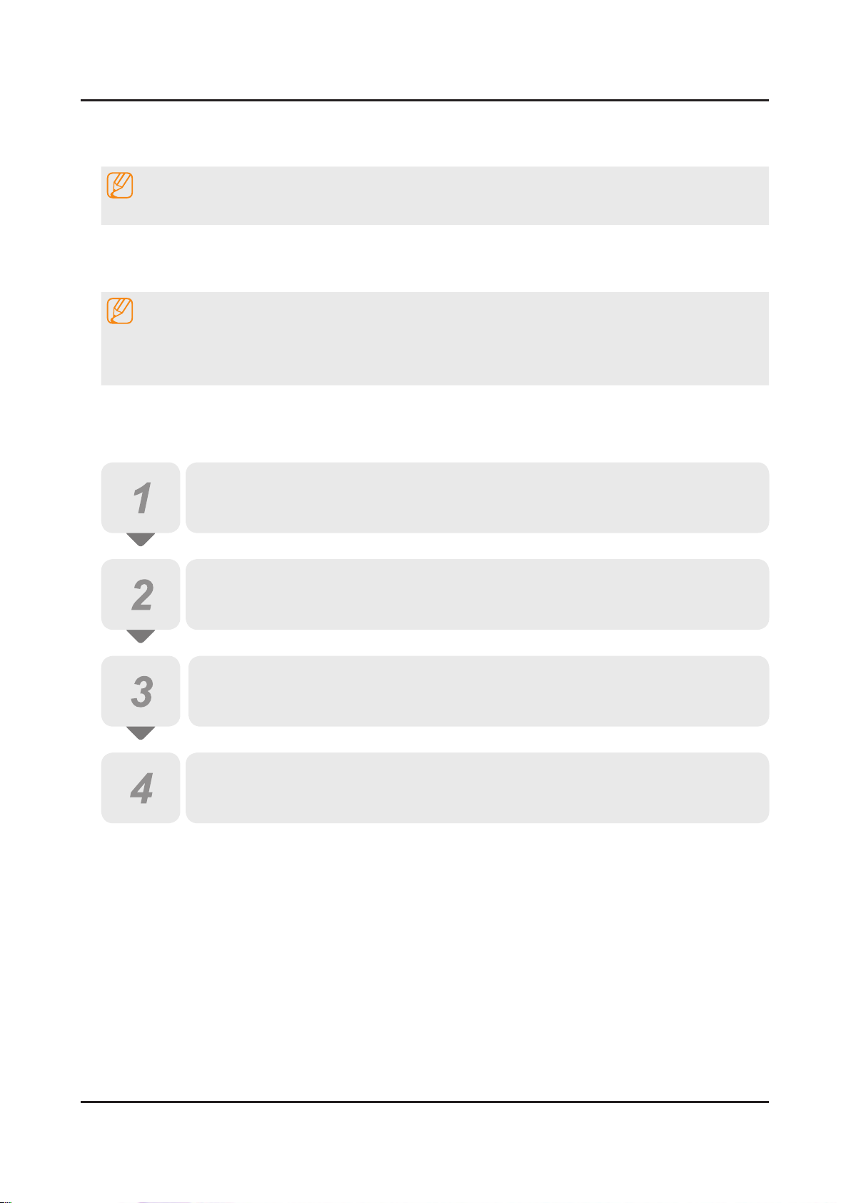
Insert a USB drive containing the rmware upgrade downloaded from samsung.com into the TV.1.
NOTE
Please be careful not to disconnect the power or remove the USB drive while upgrades are being applied.
The TV will turn off and turn on automatically after completing the rmware upgrade.2.
Please check the rmware version after the upgrades are complete.3.
the new version will have a higher number than the older version. -
NOTE
When software is upgraded, video and audio settings you have made will return to their default (factory) •
settings.
We recommend you write down your settings before beginning rmware update.•
After update is completed, restore your previous settings.4.
Main Software Upgrade
Store the sw program named "T-MST12DEUC" in USB memory stick.
Click the "MENU" key in Remote Controller.
Select "Support - Software Update - Update Now" menu.
Click the "ENTER" key.
Wait for upgrade complete.•
Check the Software Version.•
Page 52
4-52
4. Troubleshooting
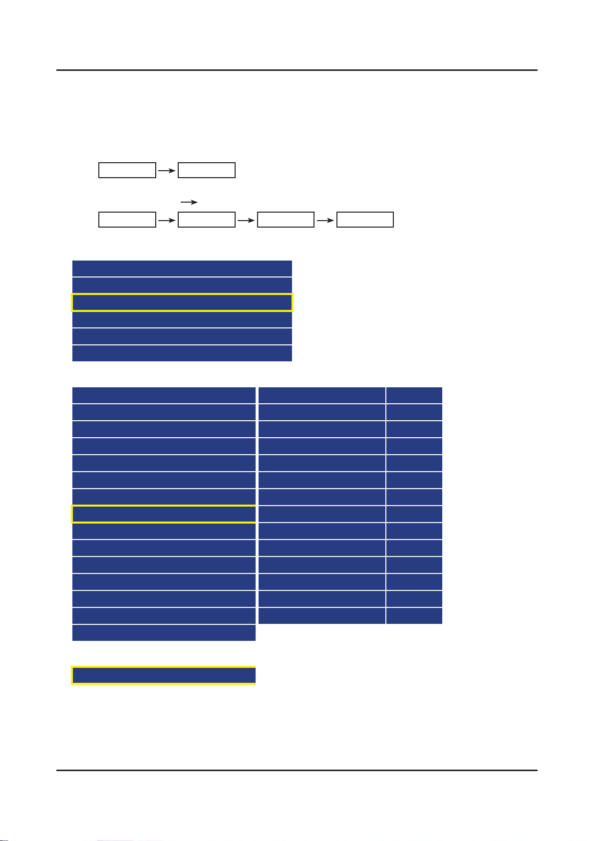
Sub Software Upgrade
USB Download
After Main Software upgrade, Enter the Factory menu by below method.1.
Factory Remocon -
Click the Remocon button continuedly. (Info key+ Factory key)•
Info Factory
Nomal Remocon -
Turn off the TV. 2 Click the Remocon button continuedly.
1•
Info Menu Mute Power
Select the “SVC”.2.
Option
Control
SVC
Expert
ADC/WB
Advanced
Select the “SUBMICOM UPGARADE”.3.
Test pattern DCC CHK SEL 0
Panel Display Time 1Hr DCC CHECK LOCAL 0x0
Tuner Status DCC CHECK TOTAL
T-CON Usb Download Failure Fuction Upgrade off
T-CON CheckSum Error Smart Hub Reset off
Tuner Margin 10 WIFI ER COUNT 0
TS Clock delay 0 BT ER COUNT 0
SUBMICOM UPGRADE off Debug Log Down
BT ADDRESS 0000 MulitACC Checksum Errow
BT UPGRADE SVC Info
BT FREEPAIRING ON TS Clock delay TC 0
SVC Reset TS Clock delay S 0
TCON_TEMP READ 0.00
TEMP LAST 60.00
DCC VERSION 0x0
CAL Data Backup ....
CAL Data Restore ....
Click the “→” remocon key.4.
SUBMICOM UPGRADE Wait
Wait for upgrade complete. -
Check the Software version. -
Page 53
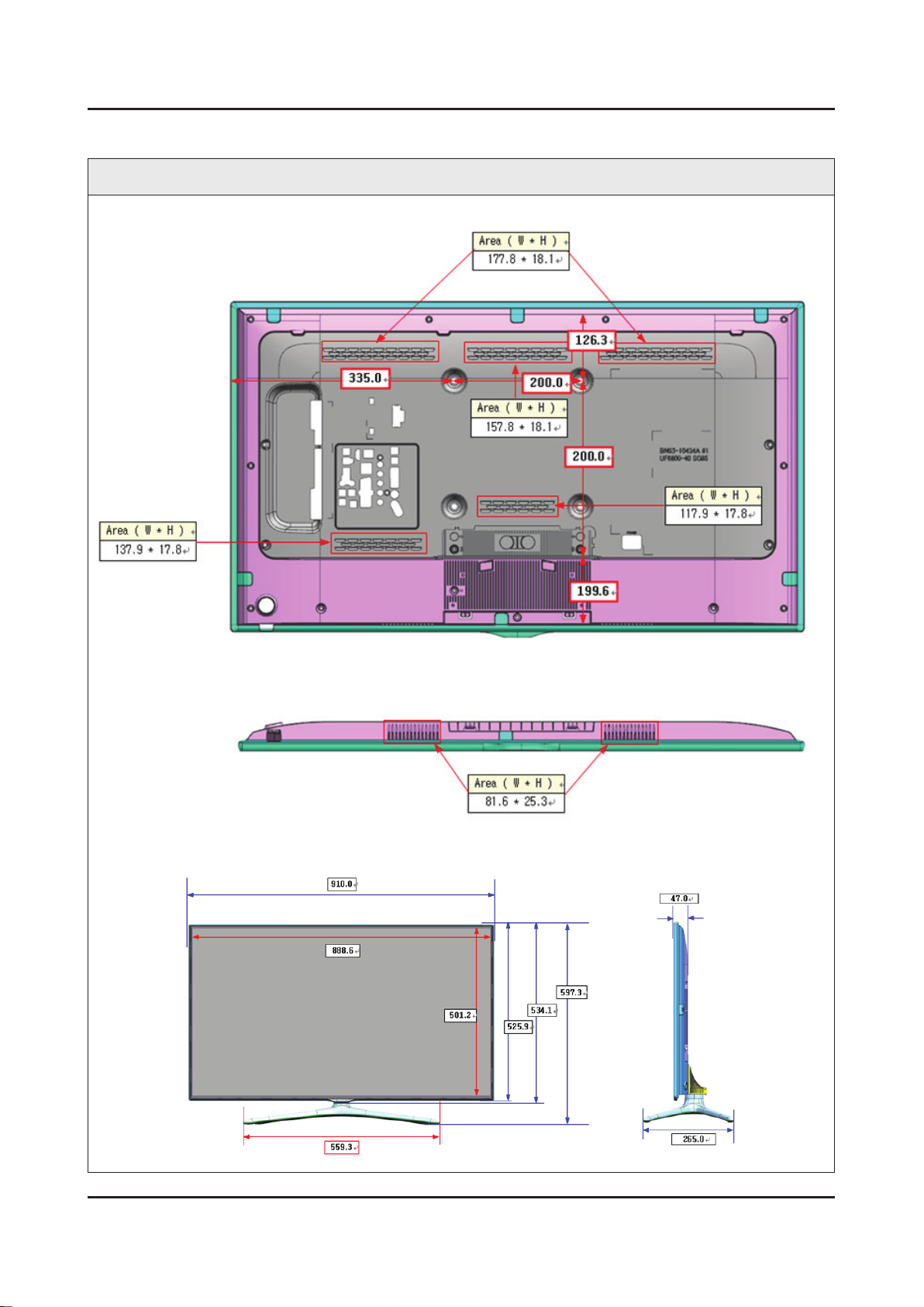
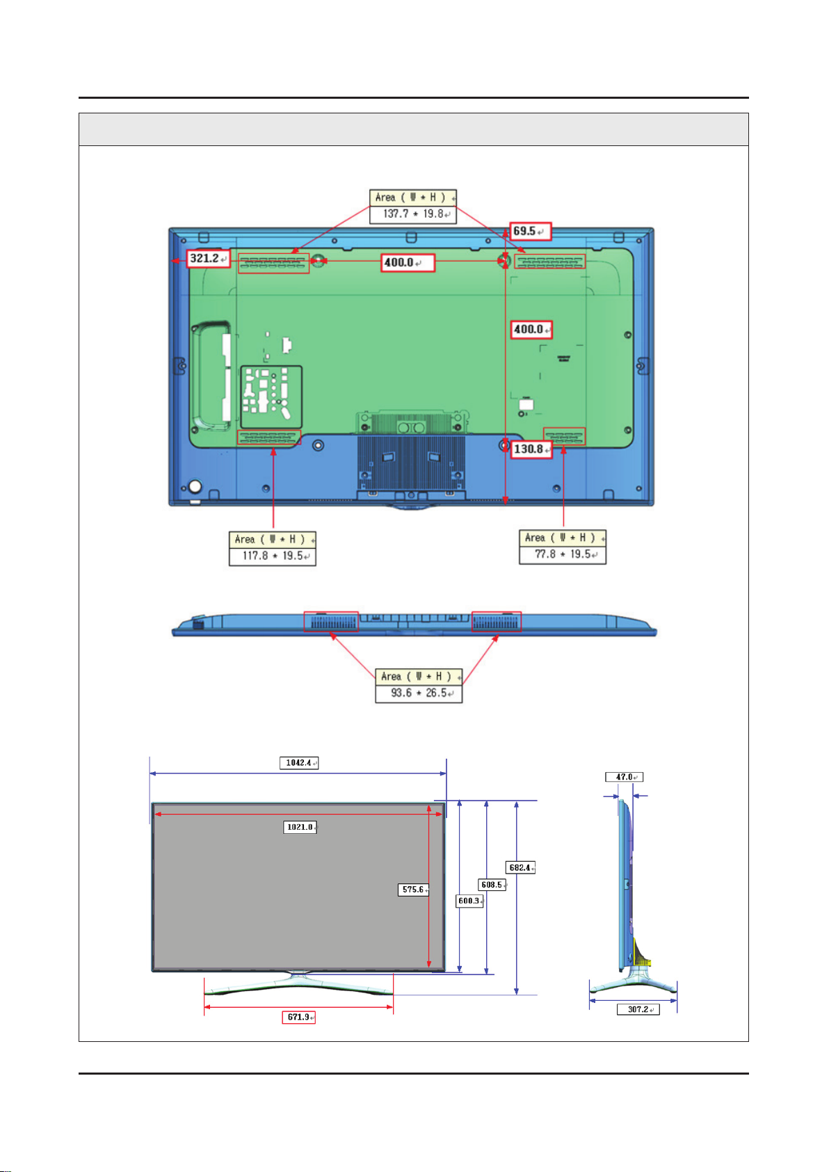
4-8. The Dimension
4-53
4. Troubleshooting
Cover Rear & Cover Middle Vent Size
40 inch
Front / Side View Dimension
Page 54
4-54
4. Troubleshooting
Cover Rear & Cover Middle Vent Size
46 inch
Front / Side View Dimension
Page 55
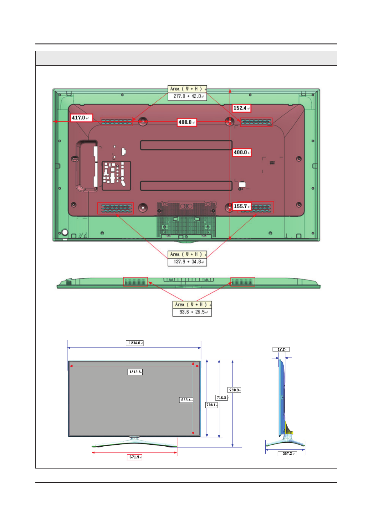
Cover Rear & Cover Middle Vent Size
4-55
4. Troubleshooting
55 inch
Front / Side View Dimension
 Loading...